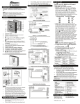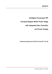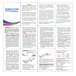
1
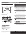
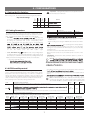
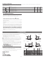
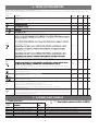
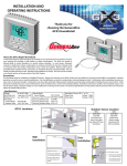
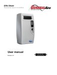
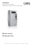
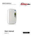
GFX50
Residential Humidistat
User manual
Revision 1.1
IMPORTANT
DISPOSAL
This product is made of metallic and plastic parts. All parts must be disposed
of according to the local standards on waste disposal.
General Filter, Inc. (GFI) bases the development of its products on
HVAC, on the continuous investments in technoloical innovations to products, procedures and strict quality processes with
in-circuit and functional testing on 100% of its products, and on the most
innovative production technoloy available on the market. GFI and its
subsidiaries nonetheless cannot guarantee that all the aspects of the
product and the software included with the product respond to the
despite the product being developed
according to start-of-the-art techniques. The customer (manufacturer,
accepts all liability and risk
relating to the
of the product in order to reach the
expected results in relation to the
installation and/or
equipment.
The GFI product is a state-of-the-art product, whose operation
in the technical documentation supplied with the product or can be
downloaded, even prior to purchase, from www.GeneralFilters.com.
Each GFI product, in relation to its advanced level o f technology, requires
such operations, which are required/indicated in the user manual, may cause
GFI accepts no liability in such cases.
product.
The customer must only use the product in the manner described in the
documentation relating to the product.
In addition to observing any further warnings described in this manual, the
following warnings must be heeded for all GFI products:
• prevent the electronic circuits from getting wet. Rain, humidity and all
types of liquids or condensate contain corrosive minerals that may damage
the electronic circuits. In any case, the product should be used or stored
in environments that comply with the temperature and humidity limits
• do not install the device in particularly hot environments. Too high
temperatures may reduce the life of electronic devices, damage them and
deform or melt the plastic parts. In any case, the product should be used
or stored in environments that comply with the temperature and humidity
• do not attempt to open the device in any way other than described in the
manual;
• do not drop, hit or shake the device, as the internal circuits and mechanisms
may be irreparably damaged;
• do not use corrosive chemicals, solvents or aggressive detergents to clean
•
the device;
technical manual.
All of the above suggestions likewise apply to the controllers, serial boards,
programming keys or any other product in the GFI product portfolio. GFI
adopts a policy of continual development. Consequently, GFI reserves
the right to make changes and improvements to any product
described in this document without prior warning.
prior warning.
The liability of GFI in relation to its products is
in the GFI limited
warranty
where allowed by applicable legislation,
in no case will GFI, its employees or subsidiaries be liable for any lost
earnings or sales, losses of data and information, costs of replacement goods
or services, damage to things or people, downtime or any direct, indirect,
incidental, actual, punitive, exemplary, special or consequential damage of
any kind whatsoever, whether contractual, extra-contractual or due to
negligence, or any other liabilities deriving from the installation, use or
impossibility to use the product, even if CAREL or its subsidiaries are warned
of the possibility of such damage.
2
Contents
1. INTRODUCTION
4
2. INSTALLATION
4
2.1 Assembly ............................................................................................... 4
2.2 Dimensions........................................................................................... 4
2.3 Electrical connections: ..................................................................... 5
3. USER INTERFACE AND MODES
6
3.1 Display and buttons .......................................................................... 6
3.2 Description of the buttons .......................................................... .. 6
4. CONFIGURATIONS
7
4.1 Setting the Dip Switches.................................................................. 7
4.2 Setting Parameters ............................................................................ 7
4.3 Auto Humidity Control..................................................................... 7
4.4 Sensor Calibration.............................................................................. 8
4.3 Additional Functions......................................................................... 8
5. FUNCTIONS
8
5.1 (H) humidity control..........................................................................8
6. TABLE OF PARAMETERS
9
7. ALARMS AND SIGNALS
9
7.1 Table of alarms......................................................................................9
8. TECHNICAL SPECIFICATIONS
10
8.2 Wiring ..................................................................................................10
3
1. INTRODUCTION
The GFX50 includes Indoor and Outdoor Temperature Sensors, Indoor Humidity Sensor and Control Unit.
2. INSTALLATION
2.1 Assembly
Important: Make sure all connections are complete before
Open the product by detaching the front from the mounting base, as
shown in Fig. 2.a:
• Remove the locking tab and screw from the the base underside.
• Slide the plastic tab back as shown to remove it from the base.
Note: For the purposes of electrical safety (EN60730-1), once the
controller has been installed, replace the plastic locking tab in the
humidistat base.
•
in the middle on the bottom of the case while lifting the front panel
upwards.
Accessories and dipswitches (Fig. 2.b)
Connector
J1
J2
Function
- Supervisor serial connection using code IROPZ48500.
- Key connector for copying the parameters. The serial
connection, if used, must be momentarily disconnected..
Not Used.
FLAT
Front-rear
polarity
Tab. 2.a
clock
Dip-switches
set
mode
aria
an
J1 per opzione
seriale o chiave
di programmazione
h ld
e
resum
J2 = sonda esterna T+H - ADCF006500
clock
FLAT Front-Rear
Fig. 2.b
set
mode
fan
hold
e
resum
Fig. 2.a
2.2 Dimensions
•
• Fasten the humidistat base to the wall using the screws supplied.
• Access the terminal block by squeezing the clips on the terminal cover.
• Make the necessary connections and run the wires through the hole
For installation, see the drilling template included in the packaging.
in the middle of the base. Separate the sensor wires from the control
wires. The diagrams are shown in Section 2.3.
3 3/8”
(86mm)
5 5/16” (135mm)
1 7/16” (36mm)
4
Fig. 2.c
2.3 Electrical connections:
GFX50
GFX50
1 2 3 4
DP
ON
Elite Steam
ON
2.3.1 Connect the GFX50 to Elite Steam for Modulating Operation
Connect Elite Steam terminals 24V and GND to GFX50 terminals GO 5 and G 6 respectivly. Do not
reverse these connections. Connect GFX50 terminal A OUT 7 to Elite Steam terminal IN. See Fig.2.a.
Note:
1. Modulating Operation requires Elite Steam signal type be changed,
See Elite Steam Manual.
2. Verify Dip Switch Settings per Figure.
DIP SWITCH SETTNGS
OFF
OFF
ON
OUTDOOR TEMP. SENSOR
(IF USED)
DIP SWITCH SETTNGS
ON
1 2 3 4
DP
ON
Elite Steam
Fig. 2.a
OFF
OFF
ON
2.3.2 Connect the GFX50 to Elite Steam for ON-OFF Operation
Connect Elite Steam terminals 24V and GND to GFX50 terminals GO 5 and G 6 respectivly. Do not
reverse these connections. Connect GFX50 terminal 1 AND 2 to Elite Steam terminal GND and IN
respectivly. Do not reverse these connectioins. See Fig.2.b.
Note:
the factory. See Elite Steam Manual.
2. Verify Dip Switch Settings per Figure.
OUTDOOR TEMP. SENSOR
(IF USED)
Fig. 2.b
GFX50
DIP SWITCH SETTNGS
1 2 3 4
ON
DP
ON
OFF
OFF
ON
GFX50 terminal 1 and 2.See Fig.3.x.
YELLOW
RED
Fig. 2.c
OUTDOOR TEMP. SENSOR
(IF USED)
2.3.4 Placement of Remote Outdoor Temperature Sensor
• Outdoor temperature sensor may not be mounted on the South side of the house or in direct sunlight.
• Outdoor temperature sensor may not be located closer than 4 feet to exhaust vents, dryer vents, etc.
• If outdoor temperature sensor is mounted in fresh air intake duct, make sure the probe is no further
than 1 foot from outside wall.
• Make sure wiring for outdoor temperature sensor is not close to other wires particularly high voltage.
• Outdoor temperature sensor must be at least 6" above expected snow line.
• Maximum conductor length of the Outdoor Temperature Sensor is 90 feet (30M).
Fig. 2.d
OUTDOOR TEMP. SENSOR
(IF USED)
5
3. USER INTERFACE AND MODES
3.1 Display and buttons
3.2 Description of the buttons
Button
corresponding symbols
side programming
buttons
. If the remote ON/OFF digital input is
connected, the function of the button may be disabled..
immediately change
the current set point
LCD display
Meaning
Selects the temperature display mode, degrees Celsius or
Fahrenheit. Whenever pressed switches the temperature units..
Used to display and where necessary change, using the UP and
If held for more than 5 sec accesses the parameters menu.
To scroll the various parameters use UP and DOWN. To edit hem
press the SET button a second time and to exit the parameters
menu press the PRG button. Access to the parameters is
protected by password if parameter PS is enabled.
Change mode manually: activates the opposite function (and
the corresponding set point) to the current (night if day or day
if night), for the set time. To change or reset the timer use the
UP and DOWN buttons to increase or decrease the time. Press a
second time to exit and return to the main menu.
If sleep mode is already active, pressing the button shows the
time remaining on the timer.
Fig. 3.a
E.g..: if in Night mode (moon symbol on) from time
band, pressing this button activates daytime mode (moon
Description of the display
Accesses the menu for setting the clock, the time bands, and
2
1
3
current time (RTC); to display the other parameters, use the
UP and DOWN arrows. To set a new value, press SET when
displaying the desired parameter and change the value using
the UP and DOWN buttons. Press a second time to exit and
return to the main menu.
Accesses the menu for displaying the temperature: current,
maximum and minimum outside (from instrument power on),
inside and outside. To display the various temperatures, press
the button repeatedly. Their meaning is displayed in the box
with the home symbol.
4
5
6
7
Also displays the value of the analogue output when “Out” is
From the main menu increases the value of the set point
10
9
In the other menus displays the variables or the parameters, or
alternatively sets the value after having pressed SET.
From the main menu decreases the value of the set point
8
Fig. 3b
In the other menus displays the variables or the parameters, or
alternatively sets the value after having pressed SET
Tab. 3.a
Key:
1.
2.
3.
4.
5.
6.
7.
8.
9.
Mode for setting the active value on the large display;
= daytime mode;
Lock mode. The parameter is not accessible;
Active time bands;
Outside/inside/maximum/minimum temperature symbol;
Mode for setting the active value on the small display;
Auto operating mode;
10. Dehum. (
) /humid. (
) operation. When the ramp symbol is on the
corresponding mode is active;
The values displayed in the LARGE and SMALL fields
(Fig 3.b.) depend on the setting of parameter dyS as
shown in the following table:
dyS
1
2
3
4
LARGE FIELD
humidity
humidity set point
humidity set point
humidity
6
SMALL FIELD
humidity set point
humidity
4. CONFIGURATIONS
4.1 Setting the Dip Switches
Important: Setting the dip switches incorrectly will cause the
the humidistat to malfunction.
Dip2
Dip3
Dip4
Dip Switch Settings
Dip1
Before closing cover, the mode must be selected using the dip switches.
ON
OFF
OFF
ON
ON
OFF
OFF
OFF
4.2 Setting Parameters
Tab. 4.a
rtC
SLP
dAy
nIt
The parameters for all operating modes feature a default value. These
values can be restored by running the “Factory set” operation. See the
table of parameters for details of the default values and settings.
• SET POINT:
clock hh:mm
manual changeover duration
start day band
start night band
def. 8 hours
def. 08:00
def. 20:00
erent set points
are used. To set these, access (SET button – 5 seconds) the mode
for setting the parameters and set the corresponding values.
For the current mode only, the value can be accessed directly
• Select parameter rtC using PRG/CLOCK and set the value using the
Once having displayed the desired parameter using the UP/
the operating mode is always daytime,
and consequently only the daytime set points are used, the night
settings are only used when the NIGHT button is pressed, manually
changing mode.
The same is true for models without the RTC function.
When the time bands are set, the CLOCK symbol is shown on the
display.
• PARAMETERS: check/set the other parameters (dIF, dS1,...) based on
the mode used.
DOWN button
.
Edit the value using the UP/DOWN buttons and then press SET.
To exit the menu, press the PRG button again
• Clock, TIME BANDS Prg/
(clock): Press the corresponding button
to display and if necessary set the default duration of the change mode
timer, display or set the RTC clock and set the Day and Night time bands.
Initially at least the following parameters need to be checked/set:
• set point for humidity control
Note:
–
–
set of parameters will be loaded by the GFX50 when changing the
4.3 AUTO humidity control
According to the level set using the up/down buttons, with a value from
In addition to the modes featured by the control algorithms, the humidity
can be controlled automatically, based on the reading of the outside
temperature sensor. The aim of this type of control is to simplify the
setting of the GFX50, changing the humidity control according to the
outside environmental conditions and therefore minimize the discomfort
of the user when moving into/out of the air-conditioned environment.
This operating mode is selected by setting parameter AUT.
code
AUt
To disable this operating mode, in the parameters menu set the value of
Aut = 0.
temperature sensor is installed.
Note: If AUTO humidity mode is enabled, the humidity setpoint
is reduced to 10% when the outdoor temperature is greater than
50° F. Disable AUTO for operation in warm outdoor temperatures.
range
def.
UOM
description of the parameter
Humidity set point level compensated according to the outside temperature
If set to OFF, the mode is disabled.
Setting one of the levels shown in the table, the controller independently sets a humidity set point in relation to
the outside temperature measurement.
Table: humidity set point according to the setting of AUT (outside temperature)
Level
Level
1
2
3
4
5
6
7
:
• When reaching 00:00 using the DOWN button the function will be
Below: 9 °F
Below: -23 °C
10%
10%
10%
10%
10%
10%
10%
-9 °F to 1 °F
-23 °C to -17 °C
10%
10%
10%
15%
20%
25%
30%
1 °F to 10 °F
-17 °C to -12 °C
10%
10%
15%
20%
25%
30%
35%
10 °F to 21 °
-12 °C to -6 °C
10%
15%
20%
25%
30%
35%
40%
21 °F to 30 °F
-6 °C to -1 °C
15%
20%
25%
30%
35%
40%
45%
30°F to 39°
-1 °C to 4 °C
20%
25%
30%
35%
40%
45%
45%
OFF
1H to 7H
39°F to 50 °F
4 °C to 10 °C
25%
30%
35%
40%
45%
45%
45%
OFF
-
Above: 50 °F
Above: 10 °C
25%
30%
35%
40%
45%
45%
45%
Tab. 4.b
7
4.4 Sensor calibration
To make up for any errors due to the length of the cables or the sensors connected, the controller features two parameters for calibrating the
values read by the sensors.
The following parameters are used:
code
description of the parameter
range
def.
UOM
CAL+ Int
CAL+ ESt
CAL+HUn
Inside temperature calibration, digital sensor or NTC
Within a maximum of ± 10 °C
Outside temperature calibration, NTC sensor
Within a maximum of ± 10 °C
Digital humidity sensor calibration.
Within a maximum of ± 15% rH
-10 to 10
0.0
°C
-10 to 10
0.0
°C
-15 to 15
0.0
% rH
Tab. 4.c
4.5 Additional functions
The controller, as well as the control algorithms for the various types of
applications (air-conditioners, boilers, heat pumps, condensing units,...),
features a series of additional functions, as described below.
Change night/day mode manually
(NIGHT)
This activates the opposite function to the current (night if day or day if
night), for the set time.
Pressing the NIGHT button once accesses the timer menu and displays
the duration.
To change the duration of the temporary mode use the UP/DOWN
buttons.
To change the value of the timer permanently, access the Prg menu and set
parameter SLP. To set the current timer to zero and return the instrument
to the original mode, press the NIGHT button, the remaining time is
displayed, then press DOWN until reaching the value 0. The instrument,
to the main menu. Once having set the timer, pressing the NIGHT button
displays the time remaining on the timer. This value can be changed at
any time.
To exit the menu press the NIGHT button again.
5. FUNCTIONS
LE=1
This section describes the humidity control modes available. The
control modes are based on parameters divided into two levels:
• Level 1, basic: main settings, always required;
• Level 2, advanced: used to customize the features of the controller.
DIP 4 = ON
10 V
Important note: Some parameters included in the advanced
level, are forced to take on default values in the basic level or are
linked to other parameters in the basic level. This especially applies to the
control differentials. In each operating mode, the links between the
various basic and avanced levels are specified.
• if level 1 is active, the level 2 parameters are not used but rather
replaced by the default values or by the link value with the level 1
parameters; the supervisor can read and set the level 2 parameters that
ectively used for the control functions.
•
ectively used when level 2 is activated.
Output
R2
DIP 4 = OFF
Output
R2
0V
dFd
% U.R
dFH
Set point hum.
LE=2
DIP 4 = ON
% U.R
Fig. 5.a
Set point dehum.
Output
DIP 4 = OFF
Output
10 V
0V
5.1 (H) humidity control
dFH
R2
dFH
R2
dFd
% U.R
% U.R
dSA
This type of control is used to send a start signal to a humidifier or
dehumidifier. The modulating output can only be used for humidification
control. Examples of using modulating output:
• for proportional humidity control of GeneralAire Elite Steam humidifiers
Set point hum.
Fig. 5.b
Set point dehum.
Parameters involved:
Code
Description
Default
LE
5.0 % rH
5.0 % rH
0.0 % rH
1
1
2
Value or
link if LE
=1
• as an additional step to the relay for humidity control.
dip1: ON
dip2: OFF
dip3: OFF
erential
erential
set
8
=0
Tab. 5.a
6. TABLE OF PARAMETERS
The parameters available depend on the level set (LE = 1 or 2).
NOTE: There are many other parameters available for use in other versions of this control. For purposes of humidification/dehumidification they may
be ignored.
code
parameter
range
default
UOM
-10 to 10
0.0
°C/
% rH
10 to 70
50.0
% rH
10 to 70
70.0
% rH
1 to 20
5.0
% rH
1 to 20
5.0
% rH
0 to 2
0
-
OFF
1H to 7H
OFF
-
set from to the set point
dSA
This value is added to or subtracted from to the set point according to the operating mode, cooling or
heating.
erential for the activation of the analogue output and the relay.
dFH
erential for the activation of the relay.
dFd
note
The parameter can have the following three values
0 - Time bands disabled.
SFH
dip4
1 - Time bands enabled:
activated.
deactivated.
2 - Time bands enabled:
deactivated.
activated.
Humidity set point automatically compensated by the outside temperature
AUt
If set to OFF the mode is disabled.
Setting one of the levels in the table, the controller independently sets a humidity set point in relation to
the outside temperature.
CAL+ Int
Inside temperature calibration, digital sensor or NTC
Within a maximum of ± 10 °C
-10 to 10
0.0
°C
CAL+ ESt
Outside temperature calibration, NTC sensor
Within a maximum of ± 10 °C
-10 to 10
0.0
°C
CAL+HUn
Digital humidity sensor calibration.
Within a maximum of ± 15% rH
-15 to 15
0.0
% rH
1, 2
1
-
°C, °F
°C
-
Parameter access level
LE
Unt
Level of access the control parameters for the active mode:
Level 1: basic access, only the essential parameters for correct operation.
Level 2: advanced access, used to set all the parameters for the selected control mode.
Temperature display mode
Sets the temperature display mode, in degrees Fahrenheit or Centigrade. Unlike direct selection using the
button, if changing the temperature display mode using parameter Unt, this becomes the default display
mode when switching the instrument on.
7. ALARMS AND SIGNALS
7.1 Table of alarms
code on
display
EE
Eth
E1
E2
Ert
ALE
Note:
three dashes “---“ are displayed.
ect
system/memory error
temperature+humidity sensor fault
built-in NTC temperature sensor fault
remote temperature sensor fault
RTC alarm
manual
automatic
automatic
automatic
automatic
stops all outputs
stops all outputs and disables the calculation of the dewpoint
stops all outputs
stops compensation if active, and control on average if enabled
-
Tab. 7.a
9
8. TECHNICAL SPECIFICATIONS
cations
Power supply
24 Vac +10 to -15%, 50/60Hz, 1 VA
22 to 35 Vdc, 0.5W
Class 2 safety power supply
Min. cable cross-section 0.5 mm2.
Power supply compatible with compactSteam (G – G0)
0 to 60°C, 32 to 140°F, 10 to 90% rH not-condensing
-20 to 70°C, -4 to 140°F, 10 to 90% rH not-condensing
±1°C from 0 to 60 °C, ±2°F from 32 to 140 °F
Operating temperature
Storage temperature
Precision of inside temperature measurement
Precision of outside temperature measurement
± 1.5°C from 0 to 40°C ± 2.0°C from -40 to 0 and 40 to 80 °C
± 3°F from 32 to 104°F ± 4°F from -40 to 32and 104 to 176 °F
0 to 10 V analogue output, not isolated, for proportional control
precision ±5%
max load 5 kΩ, max current 2 mA
EN60730-1: NO 1(1)A 250 Vac cos = 0.4, 100,000 cycles
UL-873: NO 1A resistive 24 Vac, 30 Vdc, 100,000 cycles
PILOT DUTY: 24 Vac, peak 15 A, continuous 1 A, 30,000 cycles
± 3% rH at 25°C , 77 °F
± 5% rH 0 to 60°C, 32 to 140°F
135x86x36mm
Tab. 5.a
Relay approval
Precision of humidity measurement (in models where featured)
range 10 to 90%%
Dimensions (mm):
8.2 Wiring
Digital input
Outside temperature sensor connection
with standard sensor (10 K 25 °C B=3435):
Digital input connection
Analogue output connection
Relay output connections:
cations for connections:
Non-isolated version:
direct connection of the voltage-free contact; contact closing current: 3 to 5 mA.
Isolated version:
with external power supply to 24 Vac contact: class 2 safety external power supply separate from the 24
Vac power supply to the instrument
Maximum length: 30 m, min. cable cross-section 0.5 mm2.
Maximum length 10 m, min. cable cross-section 0.5 mm2.
Maximum length 10 m, min. cable cross-section 0.5 mm2.
Maximum length 30 m, cable cross-section from 1.5 to 2.5 mm2, class 2 reinforced insulation from the
instrument.
Basic insulation between the relays.
Use copper wires approved for a temperature of 75 C.
To tighten the terminals, apply a torque of 7 Lb/In for the black terminals (SAURO)
To use the instrument in compliance with UL-873, a load with a maximum voltage 24 Vac, class 2, can be
connected to the relay output.
Tab. 5.b
Warning: All the connections, except for the relays, must be
connected to very low voltage circuits with reinforced insulation.
10
Note
43800 GRAND RIVER AVE
NOVI, MICHIGAN 43875-1115
WWW.GENERALAIRE.COM
CANADIAN GENERAL FILTERS, LTD.
400 MIDWEST POAD
TORONTO, ONTARIO M1P3A9
WWW.CGFPRODUCTS.COM
Agency:
Form GFX50-05 Rev. 1.1.
GENERAL FILTERS, INC.