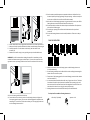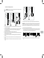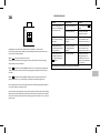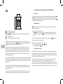
1
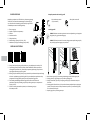
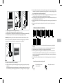
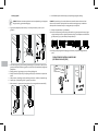
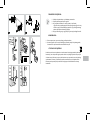
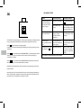
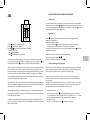
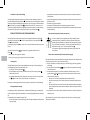
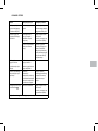
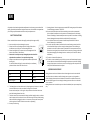
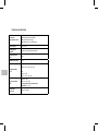
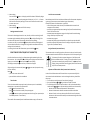
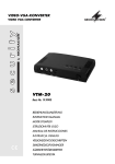
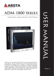
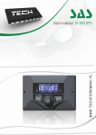
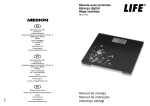
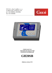
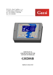
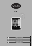
Grzałki elektryczne ZX1/ ZX4
Instrukcja obsługi
pl
Nasze wyroby zostały zaprojektowane i wyprodukowane tak, aby spełniały wszelkie
wymagania jakości, funkcjonalności i estetyki. Gratulujemy udanego zakupu
i życzymy dużo zadowolenia przy użytkowaniu nowego urządzenia.
Z ASADY BEZPIECZNEGO UŻYTKOWANIA
Uważnie przeczytaj poniższą instrukcję i zapoznaj się z ilustracjami.
1. Nigdy nie używaj urządzenia, jeżeli jest ono w jakikolwiek sposób
uszkodzone.
2. Przed podłączeniem urządzenia sprawdź, czy napięcie podane na
tabliczce znamionowej zgadza się z napięciem w domowej instalacji
elektrycznej.
3. Regularnie sprawdzaj, czy przewód zasilający nie uległ uszkodzeniu
i czy użytkowanie jest bezpieczne.
4. Przewód zasilający nie podlega naprawie. Uszkodzony przewód
powinien zostać wymieniony u Producenta lub w specjalistycznym
zakładzie naprawczym.
5. Podłączaj urządzenie wyłącznie do instalacji z uziemieniem (gniazdo
z bolcem ochronnym).
W przypadku wersji bez wtyczki (np. montaż bezpośrednio do puszki
przyłączeniowej) oznaczenia kolorystyczne przewodów są następujące:
Kolor
Oznaczenie literowe
Brązowy
L
Typ przewodu
Faza
Niebieski
N
Neutralny
Żółto-zielony
PE
Ochronny
6. Grzałka przeznaczona jest do pracy w cieczy. Dopuszcza się pracę grzałki na wolnym
powietrzu przez okres nie dłuższy niż 5 sekund. Nie dotykaj elementów metalowych
– grozi oparzeniem. Nie pozwalaj, aby przewód stykał się z rozgrzanym elementem
grzejnym.
7. Podczas montażu urządzenie nie może znajdować się pod napięciem. Wyjmij
wtyczkę z gniazda zasilającego. Przed włożeniem wtyczki do gniazda zasilającego
załóż obudowę sterownika na grzałkę. Dla prawidłowej pracy grzałki niezbędne jest
zabezpieczenie sterownika wkrętem dociskowym.
8. Nie otwieraj obudowy.
9. Moc grzałki nie może przekraczać 100% mocy grzejnika dla parametrów 75/65/20°C.
10. Ciśnienie w grzejniku nie może przekroczyć wartości podanej przez producenta
grzejnika, ani wartości 15 atm dla grzałki. Przekroczenie dopuszczalnych ciśnień
może doprowadzić do uszkodzenia grzejnika lub grzałki i spowodować zagrożenia dla
zdrowia, życia lub mienia.
11. W grzejniku elektrycznym należy pozostawić poduszkę powietrzną o odpowiedniej
objętości (patrz → Instalacja).
12. W grzejniku wodno-elektrycznym (podłączonym do sieci C.O.) przed włączeniem
grzałki i podczas jej pracy należy jeden z zaworów pozostawić otwarty w celu umożliwienia wypchnięcia nadwyżki wody spowodowanej jej rozszerzalnością cieplną.
Pozostawienie obu zaworów zamkniętych spowoduje nadmierny wzrost ciśnienia
i może uszkodzić grzałkę lub grzejnik.
13. Urządzenie przeznaczone jest do użytku domowego.
14. Urządzenie nie jest przeznaczone do użytku przez dzieci oraz osoby o ograniczonej
sprawności umysłowej lub nie posiadające koniecznej wiedzy lub doświadczenia
w zakresie obsługi podobnego sprzętu. W takim przypadku konieczny jest nadzór lub
odpowiednie przeszkolenie przez osoby odpowiedzialne za ich bezpieczeństwo.
PRZEZNACZENIE URZĄDZENIA
Grzałki są elektrycznymi urządzeniami grzewczymi i służą do instalowania w grzejnikach
przeznaczonych do ogrzewania pomieszczeń lub suszenia ręczników
i ubrań. Grzałka może być zainstalowana zarówno w grzejniku podłączonym do instalacji
C.O., pracując poza sezonem grzewczym, jak i w oddzielnym grzejniku elektrycznym.
Grzałki przeznaczone są wyłącznie do pracy w zbiornikach nie otwartych do atmosfery.
DANE TECHNICZNE
– PW (kabel prosty z wtyczką)
Oznaczenie modelu
– PB (kabel prosty bez wtyczki)
(typ kabla zasilającego) – SW (kabel spiralny z wtyczką)
– MS (przyłącze śrubowe + włącznik klawiszowy)
Zasilanie
230 V / 50 Hz
Dostępne moce
120, 200, 300, 400, 600, 800, 1000 W
Klasa izolacji
Klasa I
Przyłącze grzejnikowe
G 1/2"
Stopień ochrony
obudowy
ZX1
IPx4: wersja: –MS, –PB, –PW, –SW
ZX4
IPx4: wersja: –MS
IPx5: wersje: –PB, –PW, –SW
Typ przyłącza
elektrycznego
typ X: wersja: –MS
typ Y: wersje: –PW, –SW,
urządzenie na stałe podłączone do instalacji:
wersje –PB
Pomiar temperatury:
wewnątrz grzejnika
BUDOWA GRZAŁKI
Kompletne urządzenie serii ZX składa się z elementu grzejnego
Terma-SPLIT i sterownika montowanego na elemencie grzejnym. W zależności od modelu, grzałka może być wyposażona
w dodatkowy sterownik do obsługi zdalnej.
.
1
2.
3.
4.
5.
6.
7.
Element grzejny
Kapilara z czujnikiem temperatury
Głowica
Panel sterownika
Wkręt dociskowy
Kabel zasilający (wersja –PB, –PW, –SW)
Maskownica przyłącza śrubowego (wersja –MS)
Narzędzia potrzebne do instalacji grzałki
– klucz imbusowy rozmiar
1,5 (w zestawie)
– klucz płaski rozmiar 24
Instalacja grzałki
UWAGA! Podczas montażu urządzenie nie może znajdować się pod napięciem.
Wyjmij wtyczkę, z gniazda zasilającego.
UWAGA! Zachowaj ostrożność w czasie całego procesu napełniania grzejnika,
aby uniknąć poparzenia gorącym czynnikiem!
G RZEJNIK ELEKTRYCZNY:
. Grzejnik zasilany wyłącznie grzałką elektryczną, nie podłączony do instalacji C.O.
1
2. Czynnikiem grzewczym może być woda, woda z dodatkiem środka antyzamarzaniowego lub odpowiedni olej – warunkiem poprawnej eksploatacji jest spełnienie
wymogów producenta grzejnika i grzałki.
3. Zalanie grzejnika nadmierną ilością cieczy prowadzi do przekroczenia dopuszczalnego
ciśnienia i uszkodzenia grzejnika lub grzałki. Przy samodzielnym napełnianiu należy
postępować ściśle wg podanej poniżej instrukcji napełniania grzejnika.
4. Inne metody prawidłowego zalewania grzejnika można znaleźć na stronie
producenta. Nie należy zalewać grzejnika czynnikiem grzewczym o temperaturze
wyższej niż 65°C.
5. Grzałki nie należy montować w poziomie, ani elementem grzejnym
skierowanym w dół.
1. Wsuń element grzejny (1) do otworu gwintowanego u dołu kolektora grzejnika.
2. Dokręć głowicę el. grzejnego przy użyciu klucza płaskiego 24.
3. Dokręć element tak, aby wcięcie w złączu grzałki (A) było skierowane na wprost
lub w bok.
4. Ustaw grzejnik lekko ukośnie, tak, aby otwór wlewowy znajdował się w najwyższym
punkcie. Grzejnik nie może w żadnym momencie opierać się na sterowniku grzałki,
ani na elementach złącza!!!
5. Napełnij grzejnik czynnikiem grzewczym.
12. Ustaw maksymalną nastawę i obserwuj podnoszący się poziom czynnika grzewczego
– nadmiar czynnika może się przelewać przez górny otwór – usuń wyciekający czynnik,
aby nie dopuścić do zalania sterownika grzałki.
13. Kiedy czynnik grzewczy przestanie zwiększać swoją objętość odczekaj jeszcze 5 minut
i wyłącz grzałkę, odłącz urządzenie od gniazda/sieci zasilającej.
14. Nie czekając, aż grzejnik ostygnie, zdejmij go ostrożnie i odlej niewielką ilość czynnika
– do poziomu połowy ostatniej rurki.
15. Zamknij górny otwór przeznaczonym do tego korkiem i zamocuj grzejnik ponownie na
ścianie.
16. Podłącz grzałkę do gniazda zasilającego/ do instalacji. Urządzenie jest gotowe do
pracy.
GRZEJNIK WODNO-ELEKTRYCZNY:
6.
7.
8.
9.
Wyprostuj grzejnik i skontroluj poziom cieczy.
Upewnij się, że połączenie grzałka – grzejnik jest szczelne.
Załóż sterownik – dopasuj nacięcia na głowicy (A) oraz w gnieździe sterownika (B).
Obróć obudowę sterownika do pozycji zapewniającej wygodny dostęp.
UWAGA! Wyczuwalny opór w trakcie obracania sterownika oznacza koniec zakresu
obrotu w tym kierunku. Spróbuj obrócić sterownikiem w drugą stronę. Uszkodzenie
zabezpieczenia równoznaczne jest z utratą gwarancji na urządzenie.
1. Grzejnik podłączony do sieci C.O., w którym dodatkowo montujemy grzałkę elektryczną.
2. Instalacja C.O. musi być wyposażona w zawory umożliwiające odcięcie grzejnika.
3. Temperatura cieczy w instalacja C.O. nie może przekraczać 82stC!
4. Zaleca się odpowietrzenie grzejnika po każdej dłuższej przerwie w użytkowaniu.
Urządzenie posiada zabezpieczenie przed pracą grzejnika „na sucho” (bezpiecznik
termiczny), jego zadziałanie powoduje konieczność naprawy w serwisie producenta
(nie objęte gwarancją).
4. Grzałki nie należy montować w poziomie, ani elementem grzejnym skierowanym w
dół.
10. Dokręć wkręt dociskowy z tyłu obudowy.
11. Podłącz sterownik do gniazda zasilającego i włącz grzałkę (górny otwór pozostaje
otwarty!).
Do zalania grzejnika można użyć gorącego czynnika o temperaturze nie wyższej niż
65°C. W takim przypadku zalej grzejnik w całości, ustaw go prosto i włącz grzałkę!!
Narzędzia potrzebne do instalacji grzałki
– klucz imbusowy rozmiar
1,5 (w zestawie)
– klucz płaski rozmiar 24
Instalacja grzałki
UWAGA! Podczas montażu urządzenie nie może znajdować się pod napięciem.
Wyjmij wtyczkę, z gniazda zasilającego.
1. W grzejniku podłączonym do instalacji C.O. zakręć oba zawory i usuń czynnik
grzewczy.
8. Obróć obudowę sterownika do pozycji zapewniającej wygodny dostęp.
UWAGA! Wyczuwalny opór w trakcie obracania sterownika oznacza koniec zakresu
obrotu w tym kierunku. Spróbuj obrócić sterownikiem w drugą stronę. Uszkodzenie
zabezpieczenia równoznaczne jest z utratą gwarancji na urządzenie.
9. Dokręć wkręt dociskowy z tyłu obudowy
10. Przed uruchomieniem grzałki zakręć jeden zawór, drugi musi pozostać otwarty (sugerujemy zamknięcie zaworu z głowicą termostatyczną). Przed każdym uruchomieniem
grzałki upewnij się, że jeden zawór pozostaje otwarty!!
11. Podłącz grzałkę do gniazda zasilającego/ do instalacji. Urządzenie jest gotowe do
pracy.
PODŁĄCZENIE URZĄDZENIA W WERSJI MS
(BEZ KABLA ZASILAJĄCEGO)
2. Wsuń element grzejny (1) do otworu gwintowanego w trójniku lub w zaworze zintegrowanym lub bezpośrednio w grzejniku, w zależności od przewidzianej konfiguracji
podłączenia.
3. Dokręć głowicę el. grzejnego przy użyciu klucza płaskiego 24.
4. Dokręć element tak, aby wcięcie w złączu grzałki (A) było skierowane na wprost lub
w bok.
5. Odkręć zawory, napełnij grzejnik czynnikiem grzewczym z instalacji i odpowietrz go.
6. Upewnij się, że połączenie grzałka – grzejnik jest szczelne.
7. Załóż sterownik – dopasuj nacięcia na głowicy (A) oraz w gnieździe sterownika (B).
DEMONTAŻ URZĄDZENIA
1. Odkręć wkręt dociskowy z tyłu obudowy sterownika.
2. Zdejmij obudowę sterownika z grzałki.
3. W grzejniku w układzie C.O. zamknij zawory i spuść wodę
z grzejnika. W przypadku grzejnika elektrycznego zdejmij go ze ściany
i ustaw w pozycji uniemożliwiającej wylanie się czynnika grzewczego
podczas wykręcania elementu grzejnego.
4. Wykręć element grzejny z grzejnika przy pomocy płaskiego klucza 24.
KONSERWACJA
1. Zanim rozpoczniesz czyszczenie, odłącz grzałkę od zasilania.
2. Sterownik grzałki czyść na sucho lub wilgotną szmatką z małą ilością detergentów,
bez zawartości rozpuszczalników i materiałów ściernych.
UTYLIZACJA URZĄDZENIA
Po zakończeniu okresu użytkowania nie wolno usuwać niniejszego produktu jako odpad
komunalny, lecz należy oddać go do punktu zbiorki i recyklingu urządzeń elektrycznych
i elektronicznych. Informuje o tym symbol umieszczony na produkcie, instrukcji obsługi
i opakowaniu. Informacji o właściwym punkcie usuwania zużytych urządzeń udzieli
Państwu punkt sprzedaży lub producent. Dziękujemy za Państwa wkład w ochronę
środowiska.
ZX1
Grzałka elektryczna rozgrzewa grzejnik, w którym jest zainstalowana. Urządzenie posiada
prosty system regulacji pozwalający na pracę urządzenia z połową lub całą mocą.
Klawisz
służy do włączania i wyłączania grzałki.
Po wyłączeniu i ponownym włączeniu grzałka będzie grzała z taką samą mocą, jak przed
wyłączeniem.
Klawisz
służy do ustawienia trybu EKONOMICZNEGO – po włączeniu zapali się żółta
dioda w górnym narożniku (urządzenie zacznie pracować na zmianę włączając się
i wyłączając co 7 sekund).
Klawisz
służy do ustawienia trybu KOMFORTOWEGO (urządzenie pracuje nieprzerwanie pełną mocą) – czerwona dioda w dolnym narożniku.
Wbudowany czujnik temperatury chroni przed poparzeniem ograniczając temperaturę
grzejnika do 60°C.
Konstrukcja grzałki, jak również właściwości fizyczne czynnika grzewczego powodują, że
dolne rurki grzejnika (w szczególności ostatnie dwie) mogą mieć niższą temperaturę od
pozostałej części – takie zjawisko jest całkowicie normalne.
USUWANIE USTEREK
Problem
Potencjalna przyczyna
Rozwiązanie problemu
Grzałka jest podłączona
do gniazda zasilającego,
nie świecą żadne diody,
grzałka nie grzeje.
Grzałka nie jest włączona.
Włącz grzałkę klawiszem
.
Problem dotyczy podłączenia.
Sprawdź połączenie przewodu sieciowego, wtyczkę
oraz gniazdo elektryczne.
Grzałka nie grzeje, migają
naprzemiennie diody.
Grzałka zgłasza stan
awaryjny, nastąpiło
uszkodzenie czujnika
temperatury.
Wyłącz grzałkę i odczekaj
aż grzejnik ostygnie. Włącz
ponownie.
Grzałka nie grzeje,
diody sygnalizują właściwą
pracę.
Przepalony bezpiecznik
termiczny lub uszkodzony
element grzejny
Wyłącz grzałkę i odczekaj
aż grzejnik ostygnie. Włącz
ponownie.
Grzałka grzeje mimo wyłączenia klawiszem
.
Uszkodzone elektroniki.
Odłącz urządzenie całkowicie od sieci i poczekaj, aż
ostygnie, po czy ponownie
podłącz.
Jeżeli problem nie ustąpił skontaktuj się ze sprzedawcą.
ZX4
PRACA W TRYBIE LOKALNYM (BEZ NADAJNIKA IR)
Funkcja grzanie
W trybie lokalnym możliwe jest ustawienie 5 poziomów temperatury. Zmiany ustawień
dokonuje się za pomocą klawiszy i . Możliwe poziomy pracy to 0 (nie grzeje) oraz od
1 … 5, które odpowiadają zakresowi temperatur grzejnika od 30 … 60°C. Ikona sygnalizuje stan grzałki (świeci się, gdy grzałka grzeje).
Funkcja timera
Klawisz włączanie i wyłączanie grzałki.
Klawisz programowanie TIMERA
Klawisze i zmiana ustawień temperatury lub TIMERA.
– wskaźnik numeryczny,
– ikona : ikona GRZANIA
– ikona : ikona połączenia z nadajnikiem
Grzałka elektryczna rozgrzewa grzejnik, w którym jest zainstalowana i jednocześnie
precyzyjnie kontroluje jego temperaturę. Do regulacji temperatury służą klawisze i
natomiast świecenie ikony sygnalizuje, że grzejnik jest aktualnie dogrzewany.
Włączenie urządzenia na określony czas nie oznacza, że przez cały czas pobiera ono taką
samą, maksymalną moc. Grzałka w pierwszym, krótkim okresie po włączeniu pracuje
z mocą znamionową, aby rozgrzać grzejnik do zaprogramowanej temperatury, a następnie okresowo włącza się i wyłącza, konsumując tylko tyle energii, ile jest potrzebne do
utrzymania zadanej temperatury grzejnika przy danych warunkach zewnętrznych (patrz
rozdz. Licznik rzeczywistego czasu pracy grzałki).
Konstrukcja grzałki, jak również właściwości fizyczne czynnika grzewczego powodują, że
dolne rurki grzejnika (w szczególności ostatnie dwie) mogą mieć niższą temperaturę od
pozostałej części – takie zjawisko jest całkowicie normalne.
Sterownik ZX4 zamontowany na elemencie grzejnym SPLIT stanowi podstawową konfigurację grzałki i umożliwia korzystanie ze wszystkich podstawowych funkcji grzałki (patrz
rozdz. Praca w trybie lokalnym).
Dodatkowo, sterownik ZX4 może współpracować z zewnętrznym nadajnikiem naściennym (np. typu DT-IR1), który pozwala rozszerzyć standardowy zestaw funkcji (patrz rozdz.
Praca w trybie zdalnym).
Klawisz służy do włączenia funkcji i ustawiania czasu, po jakim grzałka zostanie
automatycznie wyłączona.
Aby uruchomić funkcję Timera:
– wciśnij krótko klawisz – na wskaźniku pojawi się czas pracy 1H (1 godzina),
– kolejne wciśnięcie klawisza wydłuża czas pracy timera (2-4 godzin).
Aby wyłączyć funkcję ustaw czas pracy na 0H (naciśnij kilkakrotnie klawisz ) lub wyłącz
i ponownie włącz grzałkę;
W trakcie trwania pracy Timer można dowolnie modyfikować :
Temperaturę grzejnika – klawisze i .
Czas pracy pozostały do wyłączenia – klawisz .
Licznik rzeczywistego czasu pracy grzałki
Unikalna funkcja pomiaru czasu pracy zlicza poszczególne okresy, w których urządzenie
pobierało prąd znamionowy (w trakcie normalnej pracy, grzałka regulując temperaturę
często wyłącza się na dłuższe okresy i praktycznie nie pobiera prądu).
W każdej chwili można sprawdzić, ile faktycznie czasu urządzenie pobierało prąd,
np. podczas całodziennej pracy. W praktyce okazuje się, że jest to do kilkudziesięciu
procent mniej!!
Wskazanie licznika powiązane jest ściśle z faktycznym zużyciem energii, a więc mnożąc
wartość licznika przez moc znamionową grzałki oraz cenę energii elektrycznej (1 kW)
możemy samodzielnie obliczyć rzeczywisty koszt zużytej energii.
1. Odczytywanie licznika:
Wciśnij i przytrzymaj klawisz na wyświetlaczu pojawią się litera E, a następnie
4 cyfry oddzielone myślnikiem (czas faktycznej pracy grzałki), np. E..0..2..‑..1..5 oznacza, że grzałka od ostatniego kasowania pracowała 2 godz. i 15 minut.
2. Kasowanie licznika:
Naciśnij i przytrzymaj długo klawisz , aż wyświetli się E 00-00.
Ustawienie na stałe trybu lokalnego
Grzałka zaprogramowana jest domyślnie na pracę w zestawie, dlatego po włączeniu
poszukuje nadajnika IR (pulsująca ikona ). Jeśli urządzenie w swoim zasięgu nie znajdzie
aktywnego nadajnika IR dioda będzie pulsować cały czas. Aby wyłączyć pulsowanie ikony
naciśnij i dłużej przytrzymaj klawisz – dioda przestanie świecić, co oznacza, że sterownik nie poszukuje nadajnika IR i odtąd będzie pracować wyłącznie w trybie lokalnym.
Aby powrócić do trybu pracy z nadajnikiem IR naciśnij i przytrzymaj klawisz .
PRACA W TRYBIE ZDALNYM (Z NADAJNIKIEM IR)
Sterownik po włączeniu powinien samoczynnie rozpocząć wyszukiwanie nadajnika IR –
sygnalizuje to pulsująca ikona . Jeśli to nie nastąpi naciśnij i przytrzymaj klawisz , aż
ikona zacznie pulsować.
Po nawiązaniu połączenia zapali się na stałe, a na wyświetlaczu widoczna jest pozioma
kreska.
W trybie zdalnym klawisze i są nieaktywne (za wyjątkiem Funkcji Timera).
Klawisz :
– naciśnij krótko, aby wyłączyć urządzenie,
– naciśnij i przytrzymaj, aby przełączyć sterownik w Tryb Lokalny.
Funkcja timera
W Trybie Zdalnym funkcja Timera działa dokładnie tak samo jak w Trybie Lokalnym, tzn.
jest obsługiwana poprzez sterownik lokalny ZX4:
– aby włączyć Timer naciśnij klawisz ,
– aby modyfikować czas pozostały do zakończenia pracy Timera naciśnij klawisz
odpowiednią ilość razy,
– aby ustawić odpowiedni poziom temperatury (w czasie pracy Timera) naciśnij klawisze i (Patrz rozdz. Praca w trybie lokalnym – funkcja timera)
Po upływie nastawionego czasu sterownik przełączy się z powrotem do Trybu Zdalnego.
Obsługa nadajnika zdalnego
Szczegółowy opis funkcji podstawowych i zaawansowanych dostępnych w nadajniku IR
zależy od zakupionego modelu nadajnika (zob. instrukcję obsługi dołączoną do nadajnika
IR).
Przykładowe funkcje nadajnika IR typu DT-IR1:
– kontrola temperatury w pomieszczeniu (grzałka w Trybie Lokalnym kontroluje temperaturę grzejnika),
– programowanie temperatury Komfortowej i Ekonomicznej oraz łatwe przełączanie
pomiędzy nimi,
– program automatycznego przełączania temperatur komfort i ekomiczny na okres 24
godzin (timer 24 h),
– automatyczny program Suszarka,
– automatyczna funkcja Antifreeze z regulowanym progiem działania,
– dopasowanie czujnika temperatury do indywidualnych warunków w pomieszczeniu
(funkcja Kalibracji).
Wykrywanie Braku Sygnału (funkcja automatyczna):
Co 10 min nadajnik wysyła sygnał kontrolny dla sprawdzenia jakości
komunikacji między urządzeniami. Zakłócenie lub brak 3 kolejnych sygnałów (30 minut) powoduje, że odbiornik ZX4 automatycznie przełącza
się na Tryb Lokalny z nastawą „0” i oczekuje na powrót komunikacji (na
wyświetlaczu pojawi „zero” i zacznie pulsować ikona ).
Po otrzymaniu sygnału kontrolnego grzałka samoczynnie powróci do
pracy zdalnej.
Zmiana adresu sterownika ZX4 (nr kanału komunikacyjnego)
Poprawna komunikacja bezprzewodowa IR wymaga aby nadajnik IR i sterownik ZX4 miały
ustawione identyczne adresy. Aby zmienić adres należy:
1. Włączyć urządzenie a następnie odłączyć je od zasilania (wyjąć wtyczkę z gniazdka
sieciowego)
2. Przytrzymać naciśnięte klawisze i , włączyć urządzenie do gniazdka sieciowego
i odczekać 5 sekund.
3. Na wyświetlaczu pojawi się na przemian wyświetlany aktualny adres np. A0. Za
pomocą klawiszy lub należy ustawić wybrany numer adresu (taki sam numer
należy ustawić w nadajniku).
– Numery od 0..3 to adresy dedykowane dla sterowników DT-IR1
– Adres A4 przeznaczony jest dla innych wybranych sterowników IR obecnych na
rynku
– Adres A5 powoduje, że sterownik ZX4 nie będzie weryfikował adresu urządzenia i
będzie wykonywał wszystkie poprawnie odebrane rozkazy niezależnie od adresu
nadajnika.
4. Po ustawieniu numeru adresu należy odczekać kilka sekund aż sterownik powróci do
normalnej pracy.
Aby dowiedzieć się, jak zmienić adres w nadajniku IR, zapoznaj się z instrukcją obsługi
dołączoną do nadajnika.
USUWANIE USTEREK
Problem
Potencjalna przyczyna
Rozwiązanie problemu
Grzałka jest podłączona
do gniazda zasilającego,
wyświetlacz LED pusty.
Problem dotyczy podłączenia.
Sprawdź połączenie przewodu sieciowego, wtyczkę
oraz gniazdo elektryczne.
Grzałka nie grzeje, na
wyświetlaczu LED miga
kod EI lub E2.
Grzałka zgłasza stan
awaryjny, nastąpiło
uszkodzenie czujnika
temperatury.
Odłącz urządzenie całkowicie od sieci
i poczekaj, aż ostygnie, po
czym ponownie podłącz.
Sterownik nieprawidłowo
nałożony na element
grzejny.
Sprawdź, czy głowica
elementu grzejnego jest
całkowicie schowana.
Odkręć wkręt dociskowy,
dociśnij obudowę do grzejnika i ponownie dokręć
wkręt dociskowy.
Krótkie pojedyncze
mignięcie kreski na
wyświetlaczu (w trybie
zdalnym).
Grzałka działa prawidłowo
– mignięcie oznacza
odebranie sygnału kontrolnego z nadajnika IR.
Grzałka z trybu zdalnego
sama przełączyła się na
tryb lokalny.
Utrudnienia
w komunikacji
z nadajnikiem: przesłonięcie okienka komunikacji IR
w którymś z urządzeń lub
złe ustawienie urządzeń.
Usunąć przeszkodę
utrudniającą komunikację
urządzeń lub zamontuj
nadajnik IR w innym
miejscu.
Grzałka grzeje mimo wyłączenia klawiszem .
Uszkodzenie elektroniki.
Odłącz urządzenie całkowicie od sieci
i poczekaj, aż ostygnie, po
czym ponownie podłącz.
Jeżeli problem nie ustąpił skontaktuj się ze sprzedawcą.
GWARANCJA
Warunki gwarancji
1. Przedmiotem gwarancji jest mikroprocesorowy sterownik do elementów grzejnych
ZX, działający w systemie TERMA-SPLIT. Nazwa modelu oraz własności wyszególnione
zostały na opakowaniu.
2. Odbierając sterownik Klient potwierdza pełnowartościowość produktu. W razie
stwierdzenia jakichkolwiek wad należy poinformować o nich Sprzedawcę – w przeciwnym wypadku przyjmuje się, że Sprzedawca wydał produkt bez wad. Dotyczy to
w szczególności jakości powierzchni obudowy sterownika.
3. Okres gwarancji wynosi 24 miesiące od daty zakupu, ale nie dłużej niż 36 misięcy od
daty produkcji.
4. Podstawą roszczeń gwarancyjnych jest karta gwarancyjna wraz z dowodem zakupu.
Nie okazanie któregokolwiek z ww. dokumentów upoważnia producenta do oddalenia roszczenia gwarancyjnego.
5. Gwarancją nie są objęte uszkodzenia powstałe:
– na skutek nieprawidłowego (niezgodnego z instrukcją) montażu, użytkowania lub
demontażu,
– w związku z zastosowaniem elementu grzejnego w sposób niezgodny z jego
przeznaczeniem,
– na skutek ingerencji w urządzenie osób nieupoważnionych,
– powstałe z winy Klienta po odbiorze od Sprzedającego.
6. Instalacja grzewcza powinna być wyposażona w zawory odcinające, umożliwiające
demontaż grzejnika lub grzałki bez opróżniania całej instalacji z czynnika grzewczego.
Problemy lub koszty powstałe na skutek braku takich zaworów w instalacji nie obciążają producenta.
7. Załączona instrukcja obsługi produktu jest integralną częścią gwarancji. Prosimy
zatem o dokładne zapoznanie się z jej treścią przed przystąpieniem do użytkowania.
8. Producent zobowiązuje się do usunięcia usterki w terminie 14 dni roboczych od daty
dostarczenia wadliwego urządzenia do siedziby producenta.
9. Jeżeli naprawa urządzenia okaże się niemożliwa, producent zobowiązuje się do dostarczenia nowego, sprawnie działającego egzemplarza o tych samych parametrach.
en
Our products have been designed and manufactured in such a way to ensure that all the
quality, functionality and aesthetic requirements are met. We would like to congratulate
you on this great purchase and would like to wish you a pleasant use.
SAFETY REGULATIONS
Please read the below instructions thoroughly and study the images carefully.
1. Never use the device that is damaged in any way.
2. Please check if the tally voltage equals the voltage of the electric
installation in your home prior to connecting the device.
3. Please check regularly if the power wire is not damaged and if the
device can be used in a safe manner.
4. Power wire is not subject to repair. Damaged power wire should be
replaced at the manufacturer’s or specialised repair shop
5. Always connect the device to the grounded installation (socket with
earthing pin).
For devices without the plug (ie. connected directly to installation),
please see below colour codes for each wire:
Colour
Letter code
Wire type
Brown
L
Live
Blue
N
Neutral
Yellow and green
PE
Earthing
6. The heating element is intended to work in a liquid agent environment. It is advised
not to turn the device on in dry conditions for longer than 5 seconds.
Do not touch metal parts – burning risk. Always make sure that the wire does not
touch the heating element that is hot.
7. The device must not be connected while being installed. Unplug the device or disconnect the power wire from electrical circuit. Put the casing on the body of the heating
element unit before plugging the device. It is necessary to secure the control panel
with the right tool in order for the device to work as required [4].
8. Do not open the casing.
9. Heating element’s electric output cannot exceed 100% heating output of the radiator
for the following parameters: 75/65/20°C.
10. Pressure inside the radiator must not exceed the pressure value recommended
by the radiator’s manufacturer or the pressure of 10 atmospheres for the heating
element. Exceeding of recommended pressures may result in the radiator or heating
element damage and cause possible threat for health, life and property.
11. An air pillow of the correct parameters should always be allowed for inside an
electric radiator (see → Installation).
12. In case of a dual fuel radiator (connected to the central heating system) one of the
valves should be left open prior to turning the heating element on and during its
operation in order for the excess water created due to its heat expansiveness to be
pushed out. Leaving both valves closed will result in excessive pressure growth which
may lead to damaging of the heating element or radiator (see → Dual fuel radiator/
Installation)
13. The device is intended for home use.
14. The device is not intended for use by children, persons with limited mental capacity
or those who do not have sufficient knowledge or experience required for handling
this type of equipment. In such cases, control or training by persons responsible for
safety of the above mentioned is required.
INTENDED USE OF DEVICE
Heating elements and control heads are electric heating devices and are intended for
installation and use in radiators used for heating interior spaces or drying towels or
clothes. Heating element and control head can be installed in a radiator connected to
the central heating system for use during the heating season as well as in an individual
electric radiator.
Heating elements are intended to operate in closed installation (not open to atmophere)
only.
TECHNICAL INFORMATION
Model code
(type of power wire)
– PW (straight cable with plug)
– PB (straight cable without plug)
– SW (spiral cable with plug)
– MS (masking cover + on/off switch)
Electric supply
230 V / 50 Hz
Heating output
available
120, 200, 300, 400, 600, 800, 1000 W
Device protection
class
Class I
Radiator connection
G 1/2"
Casing protection
mark
ZX1
IPx4: for: –MS, –PB, –PW, –SW
ZX4
IPx4: for: –MS
IPx5: for: –PB, –PW, –SW
Electric connection
type
typ X: for: –MS
typ Y: for: –PW, –SW,
Device permanently connected to the
installation: for: –PB
Temperature
measured:
inside the radiator
CONSTRUCTION OF THE HEATING ELEMENT UNIT
Complete ZX unit contains Terma‑SPLIT heating element and
controller for it. Depending on the model of the controller, it
can also be completed by a remote programmer.
1.
2.
3.
4.
5.
6.
7.
Heating element
Capillary with temperature sensor
Heating element head
Controller
Blocking thread
Power wire (versions –PB, –PW, –SW)
Masking cover for X-type connection (versions –MS)
ELECTRIC RADIATOR:
1. Radiator powered by the heating element only, not connected to the central heating
system.
2. Water, water with anti-freezing agent or the right type of oil should be used as
a heating agent – possibility of installation and correct use is conditioned by meeting
manufacturer’s requirements on the radiator and heating element.
3. Filling the radiator with too much liquid leads to exceeding of acceptable pressure
and damaging of the radiator or heating element. If you are filling the radiator
yourself, please act strictly according to the below instructions.
4. Other methods of correct filling of radiator can be found on manufacturer web site.
Radiator should not be filled with a heating agent of temperature higher than 65°C.
5. Heating element should not be fitted horizontally or turned downwards.
Tools required for installation of heating element unit
– Allen key 1.5 (included)
– spanner no 24
Installation of the heating element
WARNING! The device must not be connected to electricity during installation.
Unplug the device prior to installation.
WARNING! Please take every precaution when filling the radiator in order to
avoid being burnt by hot liquid!
1. Insert heating element (1) into the threaded opening at the bottom end of the
collector.
2. Twist the head of the heating element with a spanner no 24.
3. Position the element in such a way so that the indent in the head connection (A) was
directed towards you or sideways.
4. Put the radiator in an oblique position to make sure that the upper collector opening
is in the highest point.
The radiator must not be rested on the heating element controller or any other parts
of the connection at any time!!!
5. Fill the radiator with the heating agent.
12. Set the maximum possible temperature required and observe the liquid level rise –
the excess liquid may be slopping through the upper opening – remove excess liquid
in order not to allow for the controller to be flooded or wetted.
13. When the level of the heating agent stops rising, wait another 5 minutes, turn off the
heating element unit and disconnect the device from electricity.
14. Do not wait until the radiator cools down and pour a small amount of the liquid out –
to the mid level of the top pipe.
15. Close the upper opening of the collector with a dedicated seal and put it back
on the wall.
16. Connect the heating element unit to the socket/installation. The device is ready to
work.
DUAL FUEL RADIATOR:
6. Put the radiator back in an upright position and check the level of the liquid inside it.
7. Make sure that the connection between the radiator and the heating element is tight.
8. Install the controller – fit the indents on the head (A) with the indents in the
controller (B).
9. Position the controller casing in a way providing an easy and comfortable access.
WARNING! If you feel resistance when twisting the controller it means that you have
reached the maximum twisting span in that direction. Try to twist the controller in the
opposite direction. Any damage to the device will result in annulment of the warranty.
1. Radiator connected to the central heating system to which heating element unit
is installed additionally.
2. Central heating installation must be fitted with the valves enabling disconnecting the
radiator from the rest of the system.
3. Temperature of the heating agent from the central heating system inside the radiator
must not exceed 82°C!
4. It is recommended to bleed the radiator after every longer interval in use. The device
has a thermal fuse built in which protects the radiator from operating in dry conditions. Activation of thermal fuse means that the heating element unit will have to be
returned to the Producer for servicing (not covered by warranty).
5. Heating element must not be installed horizontally or turned downwards.
10. Secure the casing at the back with Allen key.
11. Connect the device to electricity and turn on the heating element unit (upper collector opening must be open!). One can use a hot heating agent of temperature not
exceeding 65°C. In such case, fill the entire radiator, put it in an upright position and
turn the heating element unit on!!
Tools required for installation of heating element unit.
– Allen key 1.5 (included)
– spanner no 24
Installation of the heating element unit
WARNING! The device must not be connected to electricity during installation.
Unlug the device prior to installation.
8. Position the controller casing in a way providing an easy and comfortable access.
1. In case of a radiator connected to the central heating system, close both valves and
remove the heating agent.
2. Insert the heating element (1) into the threaded opening in the tee piece, lockshield
valve integrated with tee piece or directly into the radiator, depending on the
required connection type.
3. Twist the head of the heating element using a spanner no 24.
4. Position the element in such a way so that the indent in the head connection (A) was
directed towards you or sideways.
5. Open the valves, fill the radiator with the heating agent from the installation and
bleed it.
6. Make sure that the connection between the radiator and the heating element unit is
tight.
7. Install the controller – fit the indents on the head (A) with the indents in the controller (B).
WARNING! If you feel resistance when twisting the controller that means that you have
reached the maximum twisting span in that direction. Try to twist the controller in the
opposite direction. Any damage to the device will result in annulment of the warranty.
9. Secure the casing at the back with Allen key.
10. Close one of the valves before using the heating element unit and leave the other one
open (we suggest that you close the thermostatic valve). Always make sure that one
of the valves is open prior to the use of heating element unit!!
11. Connect the heating element unit to the socket/installation. The device is ready for
use.
INSTALLATION OF THE MS VERSION OF DEVICE
(WITHOUT THE POWER SUPPLY WIRE)
DEVICE DISASSEMBLY
1. Release the screw at the back of the controller casing.
2. Take off the casing.
3. In case of a radiator connected to a central heating system, close the
valves and remove the heating agent. For electric radiators – take it off
the wall and position it in such a way to prevent pouring the heating
agent out of the radiator during disconnecting the heating element.
4. Untwist the heating element using spanner no 24.
MAINTENANCE
1. Disconnect the device from electricity prior to cleaning.
2. Heating element control head should be cleaned with a dry or damp cloth with a very
small amount of detergents, which should never contain any solvents or abrasive
agents.
PRODUCT DISPOSAL
This product should not be disposed of as general waste but should be brought to the
appropriate collection point for recycling of electric and electronic devices. This information is provided by the sign on the product, user manual and packaging. Information on
the appropriate point for used devices can be provided by Your local distributor or manufacturer of the product. Thank You for Your effort towards environment protection.
ZX1
Heating element unit heats the radiator that it is installed in. The device has
a user-friendly temperature regulation system allowing the device to work with only a
half or full of its heating output.
Button
is used to turn the device on / off.
When turned off and then back on again, the device will heat with the same heating
output as before it was turned off.
Button
is used to set the ECONOMICAL mode – this is indicated by a yellow diode
in the top left corner (the device will start operating by turning itself on and off every 7
seconds).
Button
is used to set the COMFORT mode (the device will operate with its full
output continuously) – this is indicated by a red diode in the bottom right corner.
Built-in temperature sensor protects the device from overheating, limiting the temperature of the radiator to maximum of 60°C.
Construction of the heating element unit as well as physical characteristics of the heating
agent cause that the bottom pipes (especially the two at the very bottom of the radiator)
may have a lower temperature than the remaining parts of the radiator – this is a normal
phenomenon.
PROBLEM SOLVING
Problem
Possible cause
Solution
Device is connected, no
diodes are on, heating element does not heat.
Device is not turned on
Turn the device using
button
Connection problem
Check the connection,
plug and the socket.
Heating element does not
heat, diodes are flashing
alternately.
Device signals emergency,
temperature sensor is
damaged.
Turn the device off, wait
for the radiator to cool
down and turn it back on.
Heating element does
not heat, diodes indicate
correct operation.
Thermal fuse is burnt
or heating element is
damaged.
Turn the device off, wait
for the radiator to cool
down and turn it back on.
Heating element heats
although the device has
been turned off with the
button.
Electronics damage.
Disconnect the device
completely from the
installation, wait for the
radiator to cool down and
turn it back on.
If the problem persists, please contact your local Distributor
ZX4
LOCAL MODE OPERATION (WITHOUT IR TRANSMITTER)
Heating mode
It is possible to set 5 temperature levels in the local mode. Settings are modified with
and buttons. Possible working levels are as follows: 0 (does not heat) and from 1 to 5,
each setting indicating a temperature range from 30 to 60 degrees Celsius accordingly.
icon indicates that the device is heating.
TIMER FUNCTION
button is used to turn the mode on and set the time after which the device is to be
turned off automatically.
button – turns the device on / off
button – TIMER programming
Buttons and – temperature regulation or modification of TIMER settings – numeric
sign
icon – HEATING indicator
icon – icon indicating connection to a transmitter
Heating element unit heats the radiator that it is installed in and precisely controls its
temperature at the same time. Buttons and are used to regulate temperature whilst
the icon indicates that the radiator is being preheated.
Turning the device on does not mean that it uses the same maximum power for the
whole time it is on. On turning the device on, it operates with the nominal power for
a short period of time in order to heat up the radiator to the set temperature. After
that it turns itself on and off periodically, using only as much energy as it is required
to maintain the set temperature of the radiator for current external conditions (see:
Actual working time meter).
Construction of the heating element unit as well as physical characteristics of the heating
agent cause that the bottom pipes (especially the two at the very bottom of the radiator)
may have a lower temperature than the remaining parts of the radiator – this is a normal
phenomenon.
ZX4 controller installed on the SPLIT heating element is the basic configuration of this
type of heating element unit which allows use of all the basic features of the device (see:
Local mode operation).
ZX4 controller can also cooperate with an external wall-mounted transmitter (ie. DT-IR
type), which adds additional features to the basic set (see: Remote mode operation).
In order to activate the Timer Function:
– Press button shortly – display panel will show timer working time of 1H (1 hour)
– Every subsequent pressing of the button will prolong timer working time (2-4
hours)
In order to deactivate the Timer Function, set the time to 0H (press the
times) or turn the device off and back on.
While the Timer Function is on you can modify:
– temperature of the radiator – buttons and
– Timer working time left – button
button a few
.
Actual working time meter
The unique feature measuring the actual working time of the heating element adds up
the periods during which the device was using nominal electric power (during standard
operation the device regulates the temperature and uses very little power thanks to the
fact that it turns itself off for longer periods).
It can be checked at any time how much electricity has been used, ie. during all day’s
operation. In practice it turns out to be up to a few dozens of percent less!
The number displayed on the meter reflects the actual energy consumption, therefore
you can measure the actual cost of energy used by multiplying the number on the meter
by the nominal heating output of the heating element and the price of electricity (1 kW).
1. Meter reading:
Press and hold the button – the display panel will show letter E followed by 4 digits
separated by a hyphen (actual operating time of the device), ie. E..0..2..-..1..5 means
that the device was actually working for 2 hours and 15 minutes from the last time
the meter was zeroed.
2. Meter resetting:
Press and hold the button until E 00-00 comes up.
Setting permanent local mode
The device has been designed to work in a set, therefore, it will start searching for an IR
transmitter signal immediately after being turned on ( icon will start flashing). If the
device does not find an active IR transmitter, the diode will keep flashing.
In order to turn it off, press and hold the button until the diode stops flashing which
will mean that the controller is no longer searching for the IR transmitter and will keep
working in the local mode only.
In order to go back to work with IR transmitter, press and hold the button.
REMOTE MODE OPERATION (WITH IR TRANSMITTER)
Controller should start searching for an IR transmitter signal immediately after it has
been turned on – this is indicated by icon flashing on the display panel. Should this not
happen, press and hold the button until the icon starts flashing.
After being connected, the zicon will stay on and a dash will appear.
When working in the remote mode, buttons and
the Timer Function).
Button :
– press it short to turn the device off
– press and hold to switch to the Local Mode.
are not active (except when using
Timer Function.
Timer in the Remote Mode is operated in exactly the same way as in the Local Mode,
meaning that it is operated via the ZX4 controller:
– press button to activate the Timer
– press button a few times to modify Timer operating time
– press
buttons to set the required temperature level during Timer operation (see:
Local Mode operation – Timer Function).
The controller will automatically switch to the Remote Mode on expiry of the set time.
Use of the remote transmitter
Detailed description of the basic and advanced features of the IR transmitter depends on
a given type (please see user manual attached to your IR transmitter).
Examples of features of an IR transmitter – type DT-IR1
– control of temperature inside the room (in Local Mode the device controls the
temperature of the radiator)
– possibility to program two temperature settings: Comfort and Economical and easy
switch from one to the other
– automatic temperature adjustment program for Comfort and Economical setting
during a 24hour period (24-hour timer)
– automatic timer program
– automatic Anti-freeze program with possibility to adjust the operation threshold
– possibility to adjust the temperature sensor according to the specific conditions of
a given interior (calibration feature).
No signal detection (automatic feature):
The transmitter sends a controlling signal every 10 minutes in order to check the quality
of communication between the two devices. Interruption or lack of 3 subsequent signals
(30 minutes) will result in automatic changeover of the ZX4 controller
to the Local Mode with the “0” setting. The controller will wait for communication to resume (display panel will show “0” and icon will start
flashing). Having received the controlling signal, the device will automatically return to remote operation.
Adjustment of ZX4 controller address (communication channel no)
In order for both IR transmitter and ZX4 controller to co-operate successfully, both
devices must have identical addresses. In order to change the address, please follow
these steps:
1. Turn the device on and disconnect it from electricity (unplug it)
2. Press and hold buttons and , plug in the device and wait 5 seconds
3. The LED display will show the the current address i.e. A0. Set the selected address
number with the or buttons (the same address should be set in the controller).
– Numbers 0 to 3 are addresses dedicated to DT-IR1 transmitters
– Address A4 is dedicated to other IR transmitters available on the market
– Address A5 works in such a way that controller ZX4 will not verify the device
address and it will execute all successfully received commands regardless of the
transmitter address.
4. Having set the address number, please wait a few seconds until the controller
returns to its normal function.
Please refer to the IR transmitter manual in order to find out how to adjust its address.
PROBLEM SOLVING
Problem
Possible cause
Solution
Device is connected to
electricity, LED display
panel is empty
Connection problem
Check the power wire
connection, plug and the
socket
Heating element does
not heat, LED display
panel shows E1 or
E2 code
Device signals emergency,
temperature sensor has
been damaged
Disconnect the device
completely from electricity,
wait for the radiator to cool
down and turn it back on
Controller is incorrectly
installed on the heating
element
Check if the head of
the heating element is
completely hidden. Release
the screw at the back of the
controller casing, gently
push the controller towards
the radiator and secure the
casing back
Short, single flashes of
the dash on the display
panel (in remote mode)
Controller is working
—
properly – flashes indicate
receipt of controlling signal from the IR transmitter
Device automatically
switched from remote
to local mode
Communication problem:
sensor is inaccessible or
the devices have been
incorrectly set against
each other
Remove any objects that
may be disrupting communication between the
two devices or mount the IR
transmitter in
a different location
Heating element is
heating despite being
turned off with the
button
Electronics damage
Disconnect the device
completely from electricity,
wait for the radiator to cool
down and turn it back on
If the problem persists, please contact your local distributor
WARRANTY
Warranty Terms & Conditions
1. The subject of this warranty is microprocessor-equipped controller for ZX heating
elements, which uses the TERMA-SPLIT system. Product name and characteristics are
specified on the packaging.
2. By accepting the device on purchase, the Client confirms that the product is of full
value. The Client should immediately inform the Seller of any discovered faults – otherwise it will be understood that the Product was faultless at the time of purchase.
This refers especially to any faults or damages of the control panel case.
3. Warranty period for the Product is 24 months from the date of purchase, but no
longer than 36 months from date of production.
4. Any claims made will be processed on production of the warranty card and the
evidence of purchase. Manufacturer has the right to reject any claim on the grounds
of not presenting of any of the above documents.
5. This warranty does not comprise any faults that are due to:
– incorrect (not in accordance with the manual) installation, use or disassembly,
– incorrect use of the heating element (ie. for any purpose that is not specified by
the Manufacturer as intended for this type of product),
– Product being handled by unauthorized persons,
– any faults or damages caused by the Client after having purchased and accepted
the Product.
6. Central heating installation should be fitted with lock-shield valves, enabling disassembly of the radiator or the heating element and its control head without the necessity of emptying the whole system of the heating agent. Any problems or expenses
arising from lack of such valves in the installation cannot not be used as the grounds
for any claims against manufacturer.
7. The attached Product Manual is an integral element of the Warranty. Please read it
carefully prior to the Product installation and use.
8. The Manufacturer is obliged to remove any production fault within 14 working days
from receipt of the faulty device to Manufacturer’s premises.
9. Should the repair turn out impossible, Manufacturer is obliged to replace the faulty
Product with a new, full-value unit of identical parameters.
www.zehnder.pl
MPGKE-98
Zehnder Polska Sp. z o.o.
ul. Kurpiów 14A
52-214 Wrocław
Polska