1
USER MANUAL
15P0072B1
Inverters
SINUS N
Emission 17/11/05 R.00
English
This manual is integrant and essential to the product. Carefully read the instructions contained herein as
they provide important hints for use and maintenance safety.
This device is to be used only for the purposes it has been designed to. Other uses should be considered
improper and dangerous. The manufacturer is not responsible for possible damages caused by improper,
erroneous and irrational uses.
BCH ELECTRIC LTD. is responsible for the device in its original setting.
Any changes to the structure or operating cycle of the device must be performed or authorized by the
Engineering Department of BCH ELECTRIC LTD..
BCH ELECTRIC LTD. assumes no responsibility for the consequences resulting by the use of non
original spare-parts.
BCH ELECTRIC LTD. reserves the right to make any technical changes to this manual and to the device
without prior notice. If printing errors or similar are detected, the corrections will be included in the new
releases of the manual.
BCH ELECTRIC LTD. is responsible for the information contained in the original version of the Italian
manual.
The information contained herein is the property of BCH ELECTRIC LTD. and cannot be reproduced.
BCH ELECTRIC LTD. enforces its rights on the drawings and catalogues according to the law.
E
Important User Information
Thank you for purchasing BCH ELECTRIC LTD. Variable Frequency SINUS N
SAFETY INSTRUCTIONS
Always follow safety instructions to prevent accidents and potential hazards from occurring.
In this manual, safety messages are classified as follows:
WARNING
CAUTION
Improper operation may result in serious personal injury or death.
Improper operation may result in slight to medium personal injury
or property damage.
Throughout this manual we use the following two illustrations to make you aware of safety considerations:
Identifies potential hazards under certain conditions.
Read the message and follow the instructions carefully.
Identifies shock hazards under certain conditions.
Particular attention should be directed because dangerous voltage may be present.
Keep operating instructions handy for quick reference.
Read this manual carefully to maximize the performance of SINUS N series inverter and ensure its safe
use.
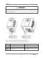
WARNING
Do not remove the cover while power is applied or the unit is in operation.
Otherwise, electric shock could occur.
Do not run the inverter with the front cover removed.
Otherwise, you may get an electric shock due to high voltage terminals or charged capacitor exposure.
Do not remove the cover except for periodic inspections or wiring, even if the input power is not
applied.
Otherwise, you may access the charged circuits and get an electric shock.
Wiring and periodic inspections should be performed at least 10 minutes after disconnecting the
input power and after checking the DC link voltage is discharged with a meter (below DC 30V).
Otherwise, you may get an electric shock.
Operate the switches with dry hands.
Otherwise, you may get an electric shock.
Do not use the cable when its insulating tube is damaged.
Otherwise, you may get an electric shock.
Do not subject the cables to scratches, excessive stress, heavy loads or pinching.
Otherwise, you may get an electric shock.
i
SINUS NE
Important User Information
CAUTION
Install the inverter on a non-flammable surface. Do not place flammable material nearby.
Otherwise, fire could occur.
Disconnect the input power if the inverter gets damaged.
Otherwise, it could result in a secondary accident and fire.
After the input power is applied or removed, the inverter will remain hot for a couple of minutes.
Otherwise, you may get bodily injuries such as skin-burn or damage.
Do not apply power to a damaged inverter or to an inverter with parts missing even if the
installation is complete.
Otherwise, electric shock could occur.
Do not allow lint, paper, wood chips, dust, metallic chips or other foreign matter into the SINUS N.
Otherwise, fire or accident could occur.
OPERATING PRECAUTIONS
(1) Handling and installation
Handle according to the weight of the product.
Do not stack the inverter boxes higher than the number recommended.
Install according to instructions specified in this manual.
Do not open the cover during delivery.
Do not place heavy items on the inverter.
Check the inverter mounting orientation is correct.
Do not drop the inverter, or subject it to impact.
Use the Type 3 grounding method for 200 V Class (Ground impedance: Below 100 ohm).
Take protective measures against ESD (Electrostatic Discharge) before touching the pcb for
inspection or installation.
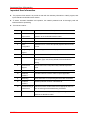
Use the inverter under the following environmental conditions:
Ambient temperature
- 10 ~ 50C
Relative humidity
90% RH or less (non-condensing)
Storage temperature
- 20 ~ 65C
Environment
Location
(non-freezing)
Protected from corrosive gas, combustible gas, oil mist
or dust
2
Altitude, Vibration
SINUS N
Max. 1,000m above sea level, Max. 5.9m/sec (0.6G) or
less
ii
Important User Information
(2) Wiring
Do not connect a power factor correction capacitor, surge suppressor, or RFI filter to the output of the
inverter.
The connection orientation of the output cables U, V, W to the motor will affect the direction of rotation
of the motor.
Incorrect terminal wiring could result in the equipment damage.
Reversing the polarity (+/-) of the terminals could damage the inverter.
Only authorized personnel familiar with BCH ELECTRIC LTD. inverter should perform wiring and
inspections.
Always install the inverter before wiring. Otherwise, you may get an electric shock or have bodily injury.
(3) Trial run
Check all parameters prior to operation. Changing parameter values might be required depending on
the load.
Always apply permissible range of voltage to the each terminal as indicated in this manual. Otherwise,
it could lead to inverter damage.
(4) Operation precautions
When the Auto restart function is selected, stay away from the equipment as a motor will restart
suddenly after a fault stop.
The Stop key on the keypad is valid only when the appropriate function setting has been made.
Prepare an emergency stop switch separately.
If a fault reset is made with the reference signal present, a sudden start will occur. Check that the
reference signal is turned off in advance. Otherwise an accident could occur.
Do not modify or alter anything inside the inverter.
Motor might not be protected by electronic thermal function of inverter.
Do not use a magnetic contactor on the inverter input for frequent starting/stopping of the inverter.
Use a noise filter to reduce the effect of electromagnetic interference. Otherwise nearby electronic
equipment may be affected.
In case of input voltage unbalance, install AC reactor. Power Factor capacitors and generators may
become overheated and damaged due to potential high frequency noise transmitted from inverter.
Before operating unit and prior to user programming, reset user parameters to default settings.
Inverter can easily be set to high-speed operations. Verify capability of motor or machinery prior to
operating unit.
Stopping torque is not produced when using the DC-Break function. Install separate equipment when
stopping torque is needed.
(5) Fault prevention precautions
Provide a safety backup such as an emergency brake which will prevent the machine and equipment
from hazardous conditions if the inverter fails.
(6) Maintenance, inspection and parts replacement
Do not conduct a megger (insulation resistance) test on the control circuit of the inverter.
Refer to Chapter 13 for periodic inspection (parts replacement).
(7) Disposal
Handle the inverter as an industrial waste when disposing of it.
(8) General instructions
Many of the diagrams and drawings in this instruction manual show the inverter without a circuit
breaker, a cover or partially open. Never run the inverter like this. Always place the cover with circuit
breakers and follow this instruction manual when operating the inverter.
iii
SINUS N
Important User Information
Important User Information
The purpose of this manual is to provide the user with the necessary information to install, program, start
up and maintain the SINUS N series inverter.
To assure successful installation and operation, the material presented must be thoroughly read and
understood before proceeding.
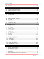
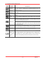
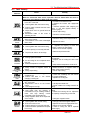
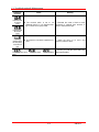
This manual contains…
Chapter
1
Title
Description
Basic information
Provides general information and precautions for safe and
& precautions
optimum use of the SINUS N series inverter.
2
Installation
Provides instructions on how to install the SINUS N inverter.
3
Wiring
Provides instructions on how to wire the SINUS N inverter.
4
Basic
Describes how to connect the optional peripheral devices to the
configuration
inverter.
Programming
Illustrates keypad features and display.
5
keypad
6
Basic operation
Provides instructions for quick start of the inverter.
7
Function list
Outlines the parameter information of the SINUS N such as
description, type, units, factory defaults, minimum/maximum
setting.
8
Control block
Shows control flow to help users easily understand operation
diagram
mode.
9
Basic functions
Provides information for basic functions in the SINUS N
10
Advanced
Indicates advanced functions used for system application.
functions
11
Monitoring
Gives information on the operating status and fault information.
12
Protective
Outlines protective functions of the SINUS N.
functions
13
14
Troubleshooting &
Defines the various inverter faults and the appropriate action to
maintenance
take as well as general troubleshooting information.
Specifications
Gives information on Input/Output rating, control type and more
details of the SINUS N inverter.
SINUS N
iv
Table of Contents
Table of Contents
1
Basic information and precautions...................................................... 1-1
1.1
Important precautions ...................................................................................... 1-1
1.2
Product Details ................................................................................................ 1-2
1.3
Removal and reinstallation ................................................................................ 1-3
2
Installation...................................................................................... 2-1
2.1
Installation precautions .................................................................................... 2-1
2.2
Dimensions ..................................................................................................... 2-3
3
Wiring ............................................................................................ 3-1
3.1
Terminal wiring ................................................................................................ 3-1
3.2
Specifications for power terminal block wiring...................................................... 3-2
3.3
I/O terminal block specification.......................................................................... 3-4
3.4
PNP/NPN selection............................................................................................ 3-5
4
Basic configuration........................................................................... 4-1
4.1
Connection of peripheral devices to the inverter................................................... 4-1
4.2
MCCB, Earth leakage circuit breaker and Magnetic contactor specification ............... 4-2
4.3
Input fuse ....................................................................................................... 4-2
5
Programming Keypad ....................................................................... 5-1
5.1
Keypad features............................................................................................... 5-1
5.2
Alpha-numeric view on the LED keypad .............................................................. 5-2
5.3
Moving to other groups..................................................................................... 5-3
5.4
How to change the codes in a group................................................................... 5-5
5.5
Parameter setting method................................................................................. 5-7
5.6
Monitoring of operation status ..........................................................................5-10
5.7
Parameter initialize .........................................................................................5-13
6
Basic operation................................................................................ 6-1
6.1
7
Frequency Setting and Basic Operation ............................................................... 6-1
Function list .................................................................................... 7-1
7.1
Drive Group .................................................................................................... 7-1
7.2
Function group 1.............................................................................................. 7-3
7.3
Function group 2.............................................................................................. 7-8
v
SINUS NE
Table of Contents
7.4
8
I/O group ...................................................................................................... 7-18
Control block diagram ...................................................................... 8-1
8.1
Frequency and Drive mode setting ...................................................................... 8-2
8.2
Accel/Decel setting and V/F control .................................................................... 8-3
9
Basic Functions................................................................................ 9-1
9.1
Frequency mode .............................................................................................. 9-1
9.2
Multi-Step frequency setting .............................................................................. 9-7
9.3
Run Command setting....................................................................................... 9-8
9.4
Accel/Decel time and unit setting ..................................................................... 9-11
9.5
V/F control .................................................................................................... 9-16
9.6
Stop mode select ........................................................................................... 9-19
9.7
Frequency limit setting.................................................................................... 9-20
10 Advanced functions .........................................................................10-1
10.1
DC brake....................................................................................................... 10-1
10.2
Jog operation ................................................................................................. 10-3
10.3
Up-Down operation......................................................................................... 10-4
10.4
3-Wire Operation............................................................................................ 10-4
10.5
Dwell operation .............................................................................................. 10-5
10.6
Slip compensation .......................................................................................... 10-6
10.7
PID Control.................................................................................................... 10-8
10.8
Auto tuning ..................................................................................................10-10
10.9
Sensorless vector control ...............................................................................10-11
10.10
Energy-saving operation ..............................................................................10-12
10.11
Speed Search .............................................................................................10-12
10.12
Auto restart try...........................................................................................10-15
10.13
Carrier frequency select...............................................................................10-16
10.14
Second motor operation ..............................................................................10-16
10.15
Parameter initialize & Lock ...........................................................................10-17
11 Monitoring .....................................................................................11-1
11.1
Operating status monitoring ............................................................................ 11-1
11.2
Monitoring the I/O terminal ............................................................................. 11-3
11.3
Monitoring fault condition ................................................................................ 11-4
11.4
Analog Output................................................................................................ 11-5
11.5
Multi-function output terminal (MO) and Relay (30AC) ........................................ 11-6
vi
SINUS N
Tables of Contents
12 Protective functions........................................................................ 12-1
12.1
Electronic Thermal ..........................................................................................12-1
12.2
Overload Warning and trip ...............................................................................12-2
12.3
Stall prevention ..............................................................................................12-3
12.4
Output phase loss protection ............................................................................12-5
12.5
External trip signal ..........................................................................................12-5
12.6
Inverter Overload............................................................................................12-6
12.7
Frequency command loss.................................................................................12-7
13 Troubleshooting & Maintenance ....................................................... 13-1
13.1
Protective functions.........................................................................................13-1
13.2
Fault Remedy .................................................................................................13-3
13.3
Precautions for maintenance and inspection .......................................................13-5
13.4
Check points ..................................................................................................13-5
13.5
Part replacements ...........................................................................................13-5
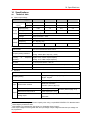
14 Specifications ................................................................................ 14-1
14.1
Technical data ................................................................................................14-1
14.2
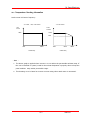
Temperature Derating Information ....................................................................14-3
vii
SINUS N
Table of Contents
NOTES:
viii
SINUS N
1. Basic information & precautions
1
Basic information and precautions
1.1
Important precautions
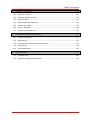
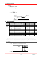
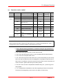
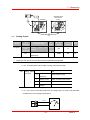
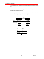
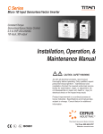
Unpacking
Inspect the inverter for any damage that may have occurred during shipping. To verify the
and
inverter unit is the correct one for the application you need, check the inverter type, output
inspection
ratings on the nameplate and the inverter is intact.
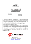
Model
Code
Input Power Ratings
Output Power Ratings
Motor Power
Bar code/Serial number
0001
Motor rating
2S
X
B
Input power
Brake
Filter
2S
X
K
2
Keypad Enclosure
0003 1,5-1,8
2S
0005
2S
2,2-3
X
X
X
B
B
B
K
K
2
K
2
2
2= IP20
2S
K
K= included
0002 0,75-1,1
B
included - I= excluded
0,4
X= excluded
0001
B= *domestic filter
kW
1phase 200-230Vac
BCH ELECTRIC LTD. inverter
SINUS N
2
* Integrated input filter EN 61800-3 edition 2 FIRST ENVIRONMENT Category C1, EN55011
gr.1 cl. B for industrial and domestic utility, EN50081-1, -2, EN50082-1, -2, EN61800-3-A11.
Accessories
If you have found any discrepancy, damage, etc., contact your sales representative.
Preparations
Instruments and parts to be prepared depend on how the inverter is operated. Prepare
of
equipment and parts as necessary.
instruments
and parts
required for
operation
Installation
To operate the inverter with high performance for a long time, install the inverter in a proper
place in the correct direction and with proper clearances (Refer to 2. Installation, P 2-1).
Wiring
Connect the power supply, motor and operation signals (control signals) to the terminal block.
Note that incorrect connection may damage the inverter and peripheral devices (Refer to 3.
Wiring, P 3-1).
1-1
SINUS N
1. Basic information & precautions
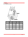
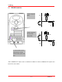
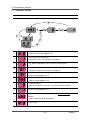
1.2
Product Details
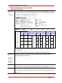
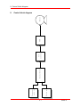
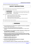
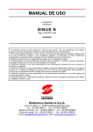
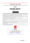
Appearance
Keypad
Status LED
Potentiometer
Display Window
STOP/RST
Front Cover:
Remove
it
Button
when
wiring and changing
Body slot: When front
parameter setting.
cover is pulled back till
this line and lifted up, it
Bottom
Cover:
Remove
wiring
it
when
input
power
can be removed from
main body. See Page 1-3
and motor.
Inverter Nameplate
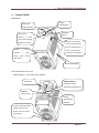
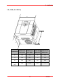
View without the front cover
Refer to Page 1-3 for front cover removal.
RUN Button
4-Way button for
parameter setting
(Up/Down/Left/Right key)
NPN/PNP
Select Switch
Analog
Input/Output
Terminal
Inverter Ground Terminal
Caut ion: Remove the
bottom cover to access
the terminal.
1-2
SINUS N
1. Basic information & precautions
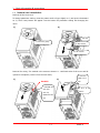
1.3
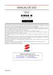
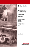
Removal and reinstallation
Removal of the front cover
To change parameter setting: Press the pattern with a finger slightly as 1) and push it downward
as 2). Then 4-way button will appear. Use this button for parameter setting and changing the
value.
1)
2)
Side slot
1. Press here gently
4-Way Button
2. Push it down
Removal for wiring: The method is the same as shown in 1. Hold both sides of the cover and lift
upward to completely remove from the main body.
1)
2. Hold both
2)
s ides of this
part
Parallel!
1. Push down the
cover unt i l
3. Lift it up to
remove.
cover top
matches the s ide
slot .
1-3
SINUS N
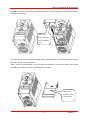
1. Basic information & precautions
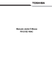
Removal for wiring input power and terminals: After removing the front cover, lift the bottom
cover up to disconnect.
Note: Input
Power Terminals
name is labeled
here.
To access control terminals: after finishing power terminal wiring, reinstall the bottom cover and
then start wiring control terminals.
Note : Use the recommended size of the cable as indicated in this manual ONLY. Using larger
size cable may lead to mis-wiring or damage the insulation.
Note: Control
Terminals name
is labeled here.
1-4
SINUS N
2. Installation
2
Installation
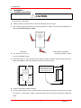
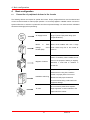
2.1
Installation precautions
CAUTION
Handle the inverter with care to prevent damage to the plastic components. Do not hold the inverter by
the front cover. It may fall off.
2
Install the inverter in a place where it is immune to vibration (5.9 m/s or less).
The inverter is under great influence of ambient temperature. Install in a location where temperature is
within the permissible range (-10~50C).
`
5cm
5cm
5cm
<Ambient
Temp Checking Location>
The inverter will be very
hot during operation. Install it
on a non-combustible surface.
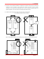
Mount the inverter on a flat, vertical and level surface. Inverter orientation must be vertical (top up) for
proper heat dissipation. Also leave sufficient clearances around the inverter.
10cm Min
5cm
5cm
Min
Min
Leave space enough to
allow cooled air flowing
easily between wiring
duct and the unit
Cooling air
Ventilating fan
10cm Min
Protect from moisture and direct sunlight.
Do not install the inverter in any environment where it is exposed to waterdrops, oil mist, dust, etc. Install
the inverter in a clean place or inside a “totally enclosed” panel which does not accept any suspended
matter.
2-1
SINUS N
2. Installation
When two or more inverters are installed or a ventilation fan is mounted in inverter panel, the inverters and
ventilation fan must be installed in proper positions with extreme care taken to keep the ambient
temperature of the inverters below the permissible value. If they are installed in improper positions, the
ambient temperature of the inverters will rise and ventilation effect will be reduced.
Install the inverter using screws or bolts to insure the inverter is firmly fastened.
< For installing multiple inverters in panel>
Heat
(NG)
Note : Take caution on proper heat ventillation when installing inverters and fan in a panel.
Air flow
2-2
SINUS N
2. Installation
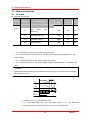
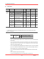
Dimensions
0.4, 1.1 kW (0.95~1.9kVA)
2.2
W
H
D
SINUS N 2S
SINUS N 2S
SINUS N 2S
SINUS N 2S
0001 XIK2
0001 XBK2
0002 XIK2
0002 XBK2
W
79
79
79
79
H
143
143
143
143
D
143
143
143
143
0.87
0.95
0.89
0.97
Dimensions
Weight
(Kg)
2-3
SINUS N
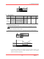
2. Installation
1.5, 3 kW (3~4.5kVA)
W
H
D
SINUS N 2S
SINUS N 2S
SINUS N 2S
SINUS N 2S
0003 XIK2
0003 XBK2
0005 XIK2
0005 XBK2
W
156
156
156
156
H
143
143
143
143
D
143
143
143
143
1.79
1.94
1.85
2
Dimensions
Weight
(Kg)
2-4
SINUS N
3. Wiring
3
Wiring
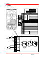
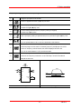
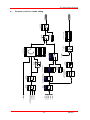
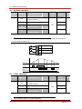
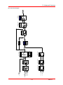
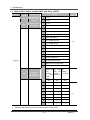
3.1
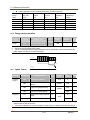
Terminal wiring
P4
30A 30B 30C
Multifunction
input
terminal
Initial setting
P4
VR
V1
I
CM
JOG : Jog operation
12V power supply for potentiometer
0-10V Analog Input terminal
0-20mA Analog Input terminal
Common Terminal for P1-P5, AM, P24
CM
Common terminal for AM terminal
Multi-function open collector output terminal
Ground T/M for MO
Multi-function relay
output terminal
A contact output
B contact output
30A 30B Common
AC line
voltage
input
P
P
P1
BX : Emergency stop
24V power for P1-P5
30C
L2
RX : Reverse run
MO
30B
Common
bar
FX : Forward run
Multi-function Analog output terminal ( 0 ~ 10V)
30A
L1
Terminal
for
Inverter
DC P/S
P1
L1
U
V
L2
W
N
U
Motor
V
N
Terminal
for
motor
CLASS B
EMI FILTER
(Option)
W
G
I
AM
EXTG
Single phase AC
input
200V ~ 230V
CM
RST : Fault reset
P5
P24
V1
Features
P1
P3
VR
MO EXTG P24 P1 P2 CM P3
Terminal
P2
P5
Earth
Ground
3-1
SINUS N
3. Wiring
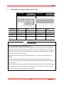
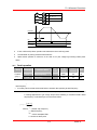
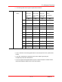
3.2
Specifications for power terminal block wiring
0001XBK2
L1
L2
0002XBK2
P
P1
0003XBK2
N
L1
U
2
Input wire size
2mm
Output wire
2mm2
Ground Wire
2mm
Terminal Lug
Tightening
0005XBK2
V
2mm
2mm
2mm ,3.5 φ
2
13kgf cm
P
P1
N
U
V
W
W
2
3.5mm
2mm2
2
L2
2
3.5mm2
2
3.5mm
2mm ,3.5 φ
2
13kgf cm
3.5mm
2
3.5mm2
2
3.5mm
2
3.5mm ,3.5 φ
2
3.5mm ,3.5 φ
15kgf cm
15kgf cm
2
Torque
CAUTION
Make sure the input power is off before wiring.
When power supply is switched off following operation, wait at least 10 minutes after LED
keypad display is off before you start working on it. If tester is available, check the voltage
between P1 and N terminals. Wiring should be performed after verifying that input voltage in
inverter DC circuitry is all exhausted.
Applying input power supply to the output terminals U, V and W causes internal inverter
damage.
Use ring terminals with insulated caps when wiring the input power and motor wiring.
Do not leave wire fragments inside the inverter. Wire fragments can cause faults, breakdowns
and malfunctions.
Never short P1 or P and N terminals. Shorting terminals may cause internal inverter damage.
Do not install a power factor capacitor, surge suppressor or RFI filters in the output side of
the inverter. Doing so may damage these components.
3-2
SINUS N
3. Wiring
WARNING
Use the Type 3 grounding method (Ground impedance: Below 100ohm).
Use the dedicated ground terminal to ground the inverter. Do not use the screw in the case or
chassis, etc for grounding.
Dedicated
Terminal
Ground
Dedicated
Terminal
Ground
Note : Remove front and bottom cover before starting grounding.
Caution : Follow the specifications below when grounding the inverter.
Model
SINUS N 2S 0001 - SINUS N 2S 0002
SINUS N 2S 0003 - SINUS N 2S 0005
2
2mm
2
2
Wire size
2mm
Lug
2mm , 3φ
2mm , 3φ
Below 100 ohm
Below 100 ohm
Ground
impedance
2
3-3
SINUS N
3. Wiring
3.3
I/O terminal block specification
Terminal
Terminal Description
Wire size
Torque
Note
(Nm)
22 AWG, 0.3 mm2
0.4
22 AWG, 0.3 mm2
0.4
22 AWG, 0.3 mm2
0.4
22 AWG, 0.3 mm2
0.4
2
22 AWG, 0.3 mm
0.4
Multi-function Analog output
22 AWG, 0.3 mm2
0.4
Multi-function open collector
2
20 AWG, 0.5 mm
0.4
20 AWG, 0.5 mm2
0.4
2
P1/P2/P3
Multi-function input T/M P1-
P4/P5
P5
CM
Common Terminal for P1P5, AM, P24
VR
12V power supply for
external potentiometer
V1
I
0-10V Analog Voltage input
0-20mA Analog Current
input
AM
MO
output T/M
EXTG
Ground T/M for MO
P24
24V Power Supply for P1-P5
20 AWG, 0.5 mm
0.4
30A
Multi-function relay A/B
20 AWG, 0.5 mm2
0.4
30B
contact output
20 AWG, 0.5 mm2
0.4
30C
30A, B Common
20 AWG, 0.5 mm2
0.4
Note: Tie the control wires more than 15cm away from the control terminals. Otherwise, it
interferes front cover reinstallation.
Note: When you use external power supply for multi-function input terminal (P1~P5), apply
voltage more than 12V to activate.
3-4
SINUS N
3. Wiring
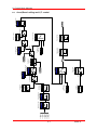
3.4
PNP/NPN selection
S4
1. When using P24
24X
[NPN]
24I
CM
Resistor
FX
Resistor
CPU
Resistor
CM
CM
S4
2. When using 24V
external power
24X
24I
CM
Resistor
supply [PNP]
FX
Resistor
CPU
Resistor
CM
CM
2. Communication option
card connector: Install
communication option card
here.
Note: MODBUS RTU option card is available for SINUS N. Refer to MODBUS RTU option card
manual for more details.
3-5
SINUS N
3. Wiring
Notes:
3-6
SINUS N
4. Basic configuration
4
4.1
Basic configuration
Connection of peripheral devices to the inverter
The following devices are required to operate the inverter. Proper peripheral devices must be selected and
correct connections made to ensure proper operation. An incorrectly applied or installed inverter can result in
system malfunction or reduction in product life as well as component damage. You must read and understand
this manual thoroughly before proceeding.
Use the power supply within the permissible
AC Supply Source
range of inverter input power rating. (See
14.Specifications)
MCCB
or
leakage
Earth Select circuit breakers with care. A large
circuit inrush current may flow in the inverter at
breaker (ELB)
power on.
Install it if necessary. When installed, do not
Magnetic Contactor
use it for the purpose of starting or stopping.
Otherwise, it could lead to reduction in
product life.
To operate the inverter with high
performance for a long time, install the
Installation and wiring
inverter in a proper place in the correct
direction and with proper clearances.
Incorrect terminal wiring could result in the
equipment damage.
Do not connect a power factor capacitor,
To motor
surge suppressor or radio noise filter to the
output side of the inverter.
4-1
SINUS N
4. Basic configuration
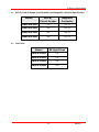
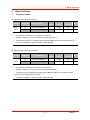
4.2
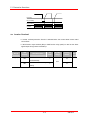
MCCB, Earth leakage circuit breaker and Magnetic contactor specification
Model
4.3
MCCB/
Circuit braker
Magnetic
Contactor
SINUS N 2S 0001
10A
AC1-12
SINUS N 2S 0002
20A
AC1-18
SINUS N 2S 0003
25A
AC1-25
SINUS N 2S 0005
32A
AC1-32
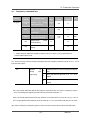
Input fuse
Model
AC input fuse
SINUS N 2S 0001
10A
SINUS N 2S 0002
20A
SINUS N 2S 0003
30A
SINUS N 2S 0005
40A
4-2
SINUS N
5. Programming keypad
5
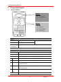
5.1
Programming Keypad
Keypad features
Display
FWD/REV LED
7 Segment LED
Buttons
RUN
STOP/RST
4-WAY BUTTON
Potentiometer
Display
FWD
Lit during forward run
Blinks when a fault occurs
REV
Lit during reverse run
7-Segment
Displays operation status and parameter information
(LED Display)
Keys
RUN
Used to give a run command
STOP/RST
STOP : Stop the operation RST : Reset faults
4-WAY BUTTON
Programming keys (UP/Down/Left/Right arrow and Prog/Ent keys)
UP
Used to scroll through codes or increase parameter value
Down
Used to scroll through codes or decrease parameter value
Left
Used to jump to other parameter groups or move a cursor to the left to change
the parameter value
Right
Used to jump to other parameter groups or move cursor to the right to change
the parameter value
Prog/Ent
Used to set the parameter value or save the changed parameter value
key
Potentiometer
Used to change the value of run frequency
5-1
SINUS N
5. Programming keypad
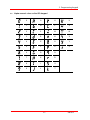
5.2
Alpha-numeric view on the LED keypad
0
A
K
U
1
B
L
V
2
C
M
W
3
D
N
X
4
E
O
Y
5
F
P
Z
6
G
Q
7
H
R
8
I
S
9
J
T
5-2
SINUS N
5. Programming keypad
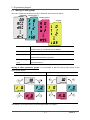
5.3
Moving to other groups
There are 4 different parameter groups in SINUS N series as shown below.
SINUS
N
Function group 1
Function group 2
I/O group
Drive group
Basic parameters necessary for the inverter to run. Parameters such
as Target frequency, Accel/Decel time are settable.
Function group 1
Basic function parameters to adjust output frequency and voltage.
Function group 2
Advanced function parameters to set parameters for such as PID
Operation and second motor operation.
I/O (Input/Output)
Parameters necessary to make up a sequence using Multi-function
group
input/output terminal.
Moving to other parameter groups is only available in the first code of each group as the
figure shown below.
Moving to other groups using the Right () key
Moving to other groups using the Left () key
*
*
Drive group
Drive group
Function
group 1
I/O group
Function
group 1
I/O group
Function
group 2
Function
group 2
st
* Target frequency can be set at 0.0 (the 1 code of drive group). Even though the preset value is 0.0, it is
user-settable. The changed frequency will be displayed after it is changed.
5-3
SINUS N
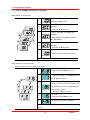
5. Programming keypad
How to move to other groups at the 1st code of each group.
-. The 1st code in drive group “0.0” will be displayed when AC input power is
1
applied.
-. Press the right arrow () key once to go to Function group 1.
-. The 1st code in Function group 1 “F 0” will be displayed.
2
-. Press the right arrow () key once to go to Function group 2.
st
-. The 1 code in Function group 2 “H 0” will be displayed.
3
-. Press the right arrow () key once to go to I/O group.
-. The 1st code in I/O group “I 0” will be displayed.
4
-. Press the right arrow () key once again to return to drive group.
st
5
-. Return to the 1 code in drive group “0.0”.
If the left arrow key () is used, the above will be executed in the reverse order.
How to move to other groups from any codes other than the 1st code
Pressing
left
or
right arrow key in
any code will return
to
first
code
of
each group.
SINUS
Function
group 2
Function
group 1
N
When you would like to move from the F 15 to function group 2
1
2
3
-. In F 15, press the Left () or Right arrow () key. Pressing the key goes to the
first code of the group.
-. The 1st code in function group 1 “F 0” is displayed.
-. Press the right arrow () key.
st
-. The 1 code in function group 2 “H 0” will be displayed.
5-4
SINUS N
5. Programming keypad
5.4
How to change the codes in a group
Code change in drive group.
st
-. In the 1 code in drive group “0.0”,
1
press the Up () key once.
-. The 2nd code in drive group “ACC” is
2
displayed.
-. Press the Up () key once.
rd
-. The 3 code “dEC” in drive group is
displayed.
3
-. Keep pressing the Up () key until the
last code appears.
-. The last code in drive group “drC” is
4
displayed.
-. Press the Up () key again.
Drive group
-. Return to the first code of drive group.
5
Use Down () key for the opposite order.
Code change in Function group 1.
When moving from the “F 0” to the “F 15” directly
1
-. Press the Prog/Ent () key in “F 0”.
-. 1 (the code number of F1) is displayed. Use
2
the Up () key to set to 5.
-. “05” is displayed by pressing the Left ()
key once to move the cursor to the left. The
3
numeral having a cursor is displayed brighter.
In this case, 0 is active.
-. Use the Up () key to set to 1.
-. 15 is set.
4
Function
group 1
-. Press the Prog/Ent () key once.
5
-. Moving to F 15 has been complete.
Function group 2 and I/O group are settable with the same
setting.
5-5
SINUS N
5. Programming keypad
For changing code from any codes other than F 0
When moving from F 1 to F 15 in Function group 1.
-. In F 1, continue pressing the Up () key
1
until F15 is displayed.
2
-. Moving to F15 has been complete.
The same rule applies to Function group 2 and I/O group.
Note: Some codes will be skipped in the middle of increment ()/decrement () for code change.
That is because it is programmed that some codes are intentionally left blank for future use or the
codes user does not use are invisible. For example, when F23 [High/low frequency limit select] is set to
“O (No) ”, F24 [High frequency limit] and F23 [Low frequency limit] are not displayed during code
change. But When F23 is set to “1(Yes)”, F23 and F24 will appear on the display.
5-6
SINUS N
5. Programming keypad
5.5
Parameter setting method
Changing parameter value in drive group
When changing ACC time from 5.0 sec to 16.0
Drive group
1
-. In the first code “0.0”, press the Up () key once to go to the second code.
-. ACC [Accel time] is displayed.
2
-. Press the Prog/Ent key () once.
-. Preset value is 5.0, and the cursor is in the digit 0.
3
-. Press the Left () key once to move the cursor to the left.
4
-. The digit 5 in 5.0 is active. Then press the Up () key once.
-. The value is increased to 6.0
5
-. Press the Left () key to move the cursor to the left.
-. 0.60 is displayed. The first 0 in 0.60 is active.
6
-. Press the Up () key once.
-. 16.0 is set.
-. Press the Prog/Ent () key once.
7
-. 16.0 is blinking.
-. Press the Prog/Ent () key once again to return to the parameter name.
8
-. ACC is displayed. Accel time is changed from 5.0 to 16.0 sec.
In step 7, pressing the Left () or Right () key while 16.0 is blinking will disable the
setting.
Note) Pressing the Left ()/ Right () /Up () /Down () key while cursor is blinking will cancel the parameter
value change.
5-7
SINUS N
5. Programming keypad
When changing run frequency to 30.05 Hz in drive group
Drive group
1
2
3
4
5
6
-. In “0.0”, press the Prog/Ent () key once.
-. The second 0 in 0.0 is active.
-. Press the Right () key once to move the cursor to the right.
-. 0.00 is displayed
-. Press the Up () key until 5 is displayed.
-. Press the Left () key once.
-. The middle digit in 0.05 is active.
-. Press the Left () key once.
-. Press the Left () key once.
-. 00.0 is displayed with the first 0 active, but the actual value 0.05 remains
7
unchanged.
-. Press the Up () key to set to 3.
-. Press the Prog/Ent () key once.
8
-. 30.0 is blinking.
-. Press the Prog/Ent () key once.
9
-. Run frequency is set to 30.0 when the blinking stops.
Three digit LED display is provided in SINUS N Series. However, digit expansion is available
using the Left()/Right() key for parameter setting and monitoring.
In step 8, pressing the Left () or Right () key while 30.0 is blinking will disable the
setting.
5-8
SINUS N
5. Programming keypad
Changing parameter values in Function 1, 2 and I/O group
When changing the parameter value of F 27 from 2 to 5
Function
group 1
1
2
3
4
5
6
7
8
-. In F0, press the Prog/Ent () key once.
-. Check the present code number.
-. Increase the value to 7 by pressing the Up () key.
-. When 7 is set, press the Left () key once.
-. 0 in 07 is active.
-. Increase the value to 2 by pressing the Up () key.
-. 27 is displayed
-. Press the Prog/Ent () key once.
-. The parameter number F27 is displayed.
-. Press the Prog/Ent () key once to check the set value.
-. The set value is 0.
-. Increase the value to 1 by pressing the Up () key.
-. Press the Prog/Ent () key once.
-. F27 is displayed after 5 stops blinking. Changing parameter value has been
9
complete.
-. Press the either Left () or Right () key once to go to the first code.
10
-. Return to F0.
5-9
SINUS N
5. Programming keypad
The above setting is also applied to change parameter values in function group 2 and I/O
group.
5.6
Monitoring of operation status
Monitoring output current in drive group
Drive group
1
2
3
4
-. In [0.0], continue pressing the Up () or Down () key until [Cur] is displayed.
-. Monitoring output current is provided in this parameter.
-. Press the Prog/Ent () key once to check the current.
-. Present output current is 5.0 A.
-. Press the Prog/Ent () key once to return to the parameter name.
-. Return to the output current monitoring code.
Other parameters in drive group such as dCL (Inverter DC link current) or vOL (Inverter output
voltage) can be monitored via the same method.
5-10
SINUS N
5. Programming keypad
How to monitor Motor rpm in drive group when the motor is rotating in 1730 rpm.
Drive group
-. Present run frequency can be monitored in the first code of Function group 1.
1
The preset frequency is 57.6Hz.
-. Continue pressing the Up () /Down () key until rPM is displayed.
2
3
4
5
-. Motor rpm can be monitored in this code.
-. Press the Prog/Ent () key once.
-. Last three digits 730 in 1730 rpm is shown on the LED.
-. Press the Left () key once.
-. First three digits 173 in 1730 rpm are shown on the LED.
-. Press the Prog/Ent () key once.
-. Return to the rPM code.
5-11
SINUS N
5. Programming keypad
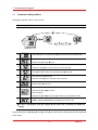
How to monitor fault condition in drive group
During
Accel
Overcurrent
trip
Current
Frequency
Drive group
STOP/RST
-. This message appears when an Overcurrent fault occurs.
1
-. Press the Prog/Ent () key once.
-. The run frequency at the time of fault (30.0) is displayed.
2
-. Press the Up () key once.
-. The output current at the time of fault is displayed.
3
-. Press the Up () key once.
-. Operating status is displayed. A fault occurred during acceleration.
4
-. Press the STOP/RST key once.
5
-. A fault condition is cleared and “nOn” is displayed.
When more than one fault occur at the same time,
-. Maximum three faults information is displayed
as shown left.
Motor
overheating
Over
voltage
Over
current
Drive group
5-12
SINUS N
5. Programming keypad
Parameter initialize
5.7
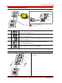
How to initialize parameters of all four groups in H93
Function
group 2
1
2
3
4
5
6
7
8
-. In H0, press the Prog/Ent () key once.
-. Code number of H0 is displayed.
-. Increase the value to 3 by pressing the Up () key.
-. In 3, press the Left () key once to move the cursor to the left.
-. 03 is displayed. 0 in 03 is active.
-. Increase the value to 9 by pressing the Up () key.
-. 93 is set.
-. Press the Prog/Ent () key once.
-. The parameter number is displayed.
-. Press the Prog/Ent () key once.
-. Present setting is 0.
-. Press the Up () key once to set to 1 to activate parameter initialize.
-. Press the Prog/Ent () key once.
-. Return to the parameter number after blinking. Parameter initialize has been
9
complete.
-. Press the either Left () or Right () key.
10
-. Return to H0.
5-13
SINUS N
5. Programming keypad
Notes:
5-14
SINUS N
6. Basic operation
6
Basic operation
6.1
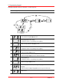
Frequency Setting and Basic Operation
Caution : The following instructions are given based on the fact that all parameters are set to factory
defaults. Results could be different if parameter values are changed. In this case, initialize parameter values
(see page 10-17) back to factory defaults and follow the instructions below.
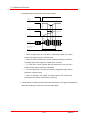
Frequency Setting via keypad & operating via terminals
1
-. Apply AC input power to the inverter.
2
-. When 0.0 appears, press the Prog/Ent () key once.
-. The second digit in 0.0 is lit as shown left.
3
-. Press the Left () key twice.
-. 00.0 is displayed and the first 0 is lit.
4
-. Press the Up () key.
-. 10.0 is set. Press the Prog/Ent () key once.
5
-. 10.0 is blinking. Press the Prog/Ent () key once.
-. Run frequency is set to 10.0 Hz when the blinking stops.
6
-. Turn on the switch between P1 (FX) and CM terminals.
-. FWD (Forward run) lamp begins to blink and accelerating frequency is displayed on the
LED.
7
-. When target run frequency 10Hz is reached, 10.0 is displayed.
-. Turn off the switch between P1 (FX) and CM terminals.
-. FWD lamp begins to blink and decelerating frequency is displayed on the LED.
8
-. When run frequency is reached to 0Hz, FWD lamp is turned off and 10.0 is displayed.
L1(R)
U
L2(S)
V
W
220VAC
10 Hz
Motor
P
Freq.
P1
N
P1(FX)
G
CM
P1(FX)-CM
Wiring
ON
OFF
Operating pattern
6-1
SINUS N
6. Basic operation
Frequency Setting via potentiometer & operating via terminals
1
-. Apply AC input power to the inverter.
2
-. When 0.0 appears Press the Up () key four times.
-. Frq is displayed. Frequency setting mode is selectable.
3
-. Press the Prog/Ent () key once.
-. Present setting method is set to 0 (frequency setting via keypad).
4
-. Press the Up () key twice.
5
-. After 2 (Frequency setting via potentiometer) is set, press the Prog/Ent () key once.
-. Frq is redisplayed after 2 stops blinking.
6
-. Turn the potentiometer to set to 10.0 Hz in either Max or Min direction.
-. Turn on the switch between P1 (FX) and CM (See Wiring below).
-. FWD lamp begins to blink and the accelerating frequency is displayed on the LED.
7
-. When run frequency 10Hz is reached, the value is displayed as shown left.
-. Turn off the switch between P1 (FX) and CM terminals.
-. FWD lamp begins to blink and the decelerating frequency is displayed on the LED.
8
-. When the run frequency is reached to 0 Hz, FWD lamp is turned off and 10.0 is
displayed as shown left.
MIN
MAX
L1(R)
U
L2(S)
V
W
220VAC
10 Hz
Àüµ¿±â
Freq.
P
P1
P1(FX)-CM
N
P1(FX)
G
CM
Wiring
ON
OFF
Operating pattern
6-2
SINUS N
6. Basic operation
Frequency setting via potentiometer & operating via the Run key
1
-. Apply AC input power to the inverter.
2
-. When 0.0 is displayed, press the Up () key three times.
-. drv is displayed. Operating method is selectable.
3
-. Press the Prog/Ent () key.
-. Check the present operating method (“1” is run via control terminal)
4
-. Press the Prog/Ent () key and then Down () key once.
5
-. After setting “0”, press the Prog/Ent () key.
-. “drv” is displayed after “0” is blinking. Operation method is set via the Run key on the
6
keypad.
-. Press the Up () key once.
-. Different frequency setting method is selectable in this code.
7
-. Press the Prog/Ent () key.
-. Check the present frequency setting method (“0” is run via keypad).
8
-. Press the Up () key twice.
9
-. After checking “2” (frequency setting via potentiometer), press the Prog/Ent () key.
-. “Frq” is displayed after “2” is blinking. Frequency setting is set via the potentiometer on
10
the keypad.
-. Turn the potentiometer to set to 10.0 Hz in either Max or Min direction.
-. Press the Run key on the keypad.
-. FWD lamp begins to blink and accelerating frequency is displayed on the LED.
11
-. When run frequency 10Hz is reached, 10.0 is displayed as shown left.
-. Press the STOP/RST key.
-. FWD lamp begins to blink and decelerating frequency is displayed on the LED.
12
-. When run frequency is reached to 0Hz, FWD lamp is turned off and 10.0 is displayed as
shown left.
L1(R)
U
L2(S)
V
W
220VAC
10 Hz
Motor
P
RUN
P1
STOP/RST
Freq.
Run key
N
G
MIN
MAX
Wiring
STOP/RST key
Operating pattern
6-3
SINUS N
6. Basic operation
Notes:
6-4
SINUS N
7. Function list
7
Function list
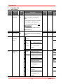
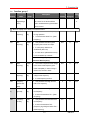
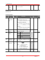
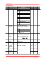
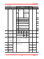
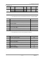
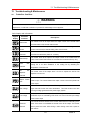
7.1
Drive Group
LED
Parameter
Min/Max
display
name
range
0.0
[Frequency
0/400
command]
[Hz]
Description
This parameter sets the frequency
Factory
Adjustable
defaults during run
Page
0.0
O
9-1
5.0
O
9-11
10.0
O
9-11
1
X
9-8
that the inverter is commanded to
output.
During Stop: Frequency Command
During Run: Output Frequency
During Multi-step operation: Multistep frequency 0.
It cannot be set greater than F21[Max frequency].
ACC
[Accel time]
0/6000
dEC
[Decel time]
[sec]
During Multi-Accel/Decel operation,
this parameter serves as Accel/Decel
time 0.
Drv
[drive mode]
0/3
(Run/Stop
0
mode)
1
2
Run/Stop via Run/Stop key on the
keypad
Run/Stop
FX : Motor forward run
via
RX : Motor reverse run
control
FX : Run/Stop enable
terminal
RX : Motor reverse
9-88
rotation
Frq
[Frequency
mode]
0/8
3
Operation via Communication Option
0
Digital
1
2
Analog
Setting via Keypad 1
0
X
9-1
Setting via Keypad 2
9-1
Setting via potentiometer
9-2
on the keypad(V0)
3
Setting via V1 terminal
9-4
4
Setting via I terminal
9-4
Setting via potentiometer
9-5
5
on the keypad + I
terminal
6
Setting via V1 + I
9-5
terminal
Setting via potentiometer
7
9-6
on the keypad + V1
terminal
7-1
SINUS N
7. Function list
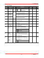
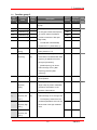
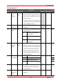
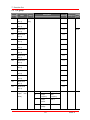
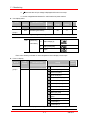
7.1
Drive Group
LED
Parameter
Min/Max
display
name
range
Description
St2
St3
CUr
rPM
Adjustable
defaults
during run
Page
Modbus-RTU
8
St1
Factory
Communication
[Multi-Step
0/400
This parameter sets Multi-Step frequency
frequency 1]
[Hz]
1 during Multi-step operation.
[Multi-Step
This parameter sets Multi-Step frequency
frequency 2]
2 during Multi-step operation.
[Multi-Step
This parameter sets Multi-Step frequency
frequency 3]
3 during Multi-step operation.
[Output
This parameter displays the output
current]
current to the motor.
[Motor RPM]
This parameter displays the number of
10.0
O
9-7
20.0
O
9-7
30.0
O
9-7
-
-
11-1
-
-
11-1
-
-
11-1
vOL
-
11-2
-
-
11-2
F
O
9-8
Motor RPM.
dCL
vOL
nOn
[Inverter DC
This parameter displays DC link voltage
link voltage]
inside the inverter.
[User display
This parameter displays the item
select]
selected at H73- [Monitoring item select].
vOL
Output voltage
POr
Output power
tOr
Torque
[Fault
This parameter displays the types of
Display]
faults, frequency and operating status at
the time of the fault
drC
[Direction of F/r
This parameter sets the direction of
motor
motor rotation when drv - [drive mode] is
rotation
set to either 0 or 1.
select]
F
Forward
r
Reverse
7-2
SINUS N
7. Function list
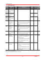
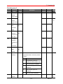
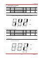
7.2
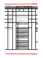
Function group 1
LED
Parameter
Min/Max
display
name
range
F0
[Jump code]
0/60
Description
This parameter sets the parameter
Factory
Adjustable
defaults
during run
1
O
5-5
0
X
9-9
0
X
9-14
0
X
9-19
5.0
X
10-1
1.0
X
10-1
50
X
10-1
1.0
X
10-1
50
X
10-2
0
X
10-2
Page
code number to jump.
F1
0
Fwd and rev run enable
Reverse run
1
Forward run disable
disable]
2
Reverse run disable
0
Linear
1
S-curve
0
Decelerate to stop
1
Stop via DC brake
2
Free run to stop
This parameter sets DC brake start
[Forward/
F2
[Accel pattern]
F3
[Decel pattern]
F4
[Stop mode
0/2
0/1
0/2
select]
F8
[DC Brake
1)
start
0/60 [Hz]
frequency.
frequency]
It cannot be set below F23 - [Start
frequency].
F9
[DC Brake
0/60 [sec]
wait time]
When DC brake frequency is
reached, the inverter holds the output
for the setting time before starting DC
brake.
F10
[DC Brake
0/200 [%]
voltage]
This parameter sets the amount of
DC voltage applied to a motor.
It is set in percent of H33 – [Motor
rated current].
F11
[DC Brake
0/60 [sec]
time]
This parameter sets the time taken
to apply DC current to a motor while
motor is at a stop.
F12
[DC Brake
0/200 [%]
start voltage]
This parameter sets the amount of
DC voltage before a motor starts to
run.
It is set in percent of H33 – [Motor
rated current].
F13
[DC Brake
start time]
0/60 [sec]
DC voltage is applied to the motor
for DC Brake start time before motor
accelerates.
7-3
SINUS N
7. Function list
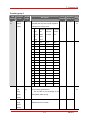
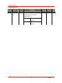
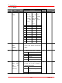
7.2
Function group 1
LED
Parameter
Min/Max
display
name
range
F14
[Time for
Description
0/60 [sec]
This parameter applies the current
magnetizing a
to a motor for the set time before
motor]
motor accelerates during Sensorless
Factory
Adjustable
defaults
during run
1.0
X
Page
1011
vector control.
1) : Set F4 to 1 (Stop via DC brake ) to view this function
F20
[Jog
0/400
frequency]
[Hz]
This parameter sets the frequency
10.0
O
10-3
60.0
X
9-20
60.0
X
9-16
0.5
X
9-20
0
X
9-20
60.0
X
0.5
X
for Jog operation.
It cannot be set above F21 – [Max
frequency].
F21
[Max
40/400 *
frequency]
[Hz]
This parameter sets the highest
frequency the inverter can output.
It is frequency reference for
Accel/Decel (See H70)
If H40 is set to 3(Sensorless vector),
it can be settable up to 300Hz *.
Caution : Any frequency cannot be
set above Max frequency.
F22
[Base
30/400
frequency]
[Hz]
The inverter outputs its rated voltage
to the motor at this frequency (see
motor nameplate). In case of using a
50Hz motor, set this to 50Hz.
F23
F24
[Start
0/10
frequency]
[Hz]
[Frequency
0/1
The inverter starts to output its
voltage at this frequency.
It is the frequency low limit.
This parameter sets high and low
high/low limit
limit of run frequency.
select]
F25
[Frequency
0/400
2)
high limit]
[Hz]
This parameter sets high limit of the
run frequency.
It cannot be set above F21 – [Max
frequency].
F26
[Frequency
0/400
low limit]
[Hz]
This parameter sets low limit of the
run frequency.
It cannot be set above F25 [Frequency high limit] and below F23 –
[Start frequency].
7-4
SINUS N
7. Function list
7.2
Function group 1
LED
Parameter
Min/Max
display
name
range
F27
[Torque
0/1
Boost select]
F28
[Torque boost
0/15 [%]
Description
0
Manual torque boost
1
Auto torque boost
This parameter sets the amount of
in forward
torque boost applied to a motor during
direction]
forward run.
Factory
Adjustable
defaults
during run
0
X
9-18
5
X
9-18
5
X
9-18
0
X
9-16
Page
It is set in percent of Max output
voltage.
F29
[Torque boost
This parameter sets the amount of
in reverse
torque boost applied to a motor during
direction]
reverse run.
It is set as a percent of Max output
voltage
F30
[V/F pattern]
0/2
0
{Linear}
1
{Square}
9-16
2
{User V/F}
9-17
F31
[User V/F
0/400
3)
frequency 1]
[Hz]
F32
[User V/F
0/100
voltage 1]
[%]
[User V/F
0/400
frequency 2]
[Hz]
[User V/F
0/100
voltage 2]
[%]
parameters cannot be set above those
[User V/F
0/400
of higher-numbered.
frequency 3]
[Hz]
[User V/F
0/100
voltage 3]
[%]
[User V/F
0/400
frequency 4]
[Hz]
[User V/F
0/100
voltage 4]
[%]
[Output
40/110
voltage
[%]
F33
F34
F35
F36
F37
F38
F39
adjustment]
This parameter is active when F30 –
15.0
X
25
X
30.0
X
50
X
45.0
X
75
X
60.0
X
100
X
100
X
9-17
[V/F pattern] is set to 2 {User V/F}.
It cannot be set above F21 – [Max
frequency].
The value of voltage is set in
percent of H70 – [Motor rated voltage].
The values of the lower-numbered
This parameter adjusts the amount
of output voltage.
The set value is the percentage of
input voltage
7-5
SINUS N
9-17
7. Function list
7.2
Function group 1
LED
Parameter
Min/Max
display
name
range
F40
[Energy-
0/30 [%]
Description
saving level]
F50
[Electronic
This parameter decreases output
Factory
Adjustable
defaults
during run
0
0
voltage according to load status.
0/1
thermal
Page
1012
This parameter is activated when the
0
0
12-1
150
0
12-1
100
0
0
0
150
0
10
0
motor is overheated (time-inverse).
select]
2) Only displayed when F24 (Freq High/Low limit select) is set to 1.
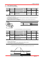
3): Set F30 to 2 (User V/F) to display this parameter.
F51
[Electronic
50/200
4)
thermal level
[%]
This parameter sets max current
capable
for 1 minute]
of
flowing
to
the
motor
continuously for 1 minute.
The set value is the percentage of
H33 – [Motor rated current].
It cannot be set below F52 –
[Electronic thermal level for continuous].
F52
[Electronic
This parameter sets the amount of
thermal level
current to keep the motor running
for
continuously.
continuous]
It cannot be set higher than F51 –
[Electronic thermal level for 1 minute].
F53
[Motor
0/1
0
Standard motor having cooling
cooling
fan directly connected to the
method]
shaft
1
A motor using a separate motor
to power a cooling fan.
F54
[Overload
30/150
warning level] [%]
This parameter sets the amount of
current to issue an alarm signal at a
relay or multi-function output terminal
(see I54, I55).
The set value is the percentage of
H33- [Motor rated current].
F55
[Overload
0/30
warning time]
[sec]
This parameter issues an alarm
signal when the current greater than
F54- [Overload warning level] flows to
the motor for F55- [Overload warning
time].
7-6
SINUS N
12-2
7. Function list
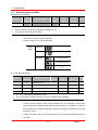
7.2
Function group 1
LED
Parameter
Min/Max
display
name
range
F56
[Overload trip
0/1
Description
select]
F57
This parameter turns off the inverter
Factory
Adjustable
defaults
during run
1
0
180
0
60
0
Page
12-3
output when motor is overloaded.
[Overload trip
30/200
level]
[%]
This parameter sets the amount of
overload current.
The value is the percentage of H33[Motor rated current].
F58
[Overload trip
0/60
time]
[sec]
This parameter turns off the inverter
output when the F57- [Overload trip
level] of current flows to the motor for
F58- [Overload trip time].
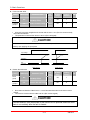
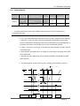
F59
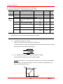
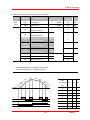
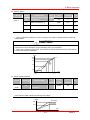
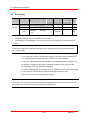
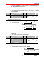
[Stall
0/7
This parameter stops accelerating during
prevention
acceleration, decelerating during constant
select]
speed run and stops decelerating during
0
X
12-3
150
X
12-3
deceleration.
During
During
Deceleration constant
During
Acceleration
speed
Bit 2
F60
[Stall
30/150
prevention
[%]
Bit 1
Bit 0
0
-
-
-
1
-
-
2
-
-
3
-
4
-
-
5
-
6
-
7
This parameter sets the amount of current
to activate stall prevention function during
level]
Accel, constant or Decel run.
The set value is the percentage of the
H33- [Motor rated current].
4): Set F50 to 1 to display this parameter
7-7
SINUS N
7. Function list
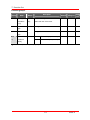
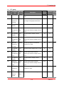
7.3
Function group 2
LED
Parameter
Min/Max
display
name
range
H0
[Jump code]
1/95
Factory
Adjustable
defaults
during run
1
O
5-5
This parameter stores information
nOn
-
11-4
Description
This parameter sets the code number
Page
to jump.
H1
[Fault history 1] -
H2
[Fault history 2] -
on the types of faults, the frequency,
nOn
-
H3
[Fault history 3] -
the current and the Accel/Decel
nOn
-
H4
[Fault history 4] -
condition at the time of fault (see
nOn
-
[Fault history 5] -
page 1000).
nOn
-
0
O
5.0
X
0.0
X
0
X
10.0
X
15.0
X
20.0
X
H5
The last fault is automatically
stored in the H 1- [Fault history 1].
H6
[Reset fault
0/1
history]
H7
This parameter clears the fault
history saved in H 1-5.
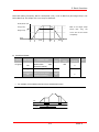
[Dwell
F23/400
frequency]
[Hz]
When run frequency is issued,
motor starts to accelerate after dwell
frequency is applied to the motor
during H8- [Dwell time].
[Dwell frequency] can be set
within the range of F21- [Max
frequency] and F23- [Start
frequency].
H8
[Dwell time]
0/10 [sec]
This parameter sets the time for
dwell operation.
H10
[Skip
0/1
This parameter sets the frequency
frequency
range to skip to prevent undesirable
select]
resonance and vibration on the
structure of the machine.
H11
[Skip
0/400
1)
frequency low
[Hz]
limit 1]
H12
H13
Run frequency cannot be set
within the range of H11 through H16.
The frequency values of the low
[Skip
numbered parameters cannot be set
frequency high
above those of the high numbered
limit 1]
ones.
[Skip
frequency low
limit 2]
7-8
SINUS N
9-21
7. Function list
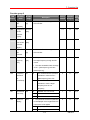
7.3
Function group 2
LED
Parameter
Min/Max
display
name
range
H14
Description
[Skip
Factory
Adjustable
defaults during run
Page
25.0
X
30.0
X
35.0
X
40
X
40
X
0
O
12-5
0
O
9-10
0
O
frequency high
limit 2]
H15
[Skip
frequency low
limit 3]
H16
[Skip
frequency high
limit 3]
H17
S-Curve
1/100 [%]
Set the speed reference value to form
accel/decel
a curve at the start during accel/decel.
start side
If it is set higher, linear zone gets
9-14
smaller.
H18
S-Curve
1/100 [%]
Set the speed reference value to form
accel/decel
a curve at the end during accel/decel.
end side
If it is set higher, linear zone gets
smaller.
H19
H20
[Output phase
0/1
Inverter turns off the output when
loss protection
the phase of the inverter output (U,
select]
V, W) is not properly connected.
[Power On
0/1
Start select]
This parameter is activated when
drv is set to 1 or 2 (Run/Stop via
Control terminal).
Motor starts acceleration after AC
power is applied while FX or RX
terminal is ON.
H21
[Restart after
0/1
fault reset]
This parameter is active when drv
is set to 1 or 2 (Run/Stop via Control
terminal).
Motor accelerates after the fault
condition is reset while the FX or RX
terminal is ON.
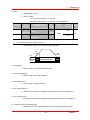
1) Set H10 to 1 to be displayed.
# H17, 18 is used when F2, F3 is set to 1 S-Curve.
7-9
SINUS N
7. Function list
Function group 2
LED
Parameter
Min/Max
display
name
range
0/15
Factory
Description
defaults during run
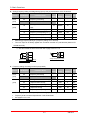
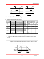
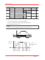
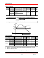
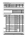
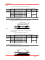
H22
[Speed
This parameter is active to prevent any
2)
Search
possible fault when the inverter outputs its
Select]
voltage to the running motor.
1.
2.Restart 3.Operation 4.Normal
H20-
after
[Power instant
H23
[Current
80/200
level
[%]
acceler-
occurred
ation
power
start]
failure
Bit 3
Bit 2
Bit 1
Bit 0
0
-
-
-
-
1
-
-
-
2
-
-
3
-
-
4
-
-
-
5
-
-
6
-
7
-
8
-
-
-
9
-
-
10
-
-
-
12
-
-
13
-
14
-
15
This parameter limits the amount of
0
O
Speed
100
O
[P
The set value is the percentage of the
H33- [Motor rated current].
gain 0/9999
during
It is the Proportional gain used for
100
O
Speed Search PI controller.
Speed
search]
7-10
10-
1012
search]
H24
Page
12
current during speed search.
during
after fault
On
11
Adjustable
SINUS N
7. Function list
H25
[I
gain 0/9999
during
It is the Integral gain used for Speed
1000
O
search PI controller.
speed
search]
2) #4.Normal acceleration has first priority. Even though #4 is selected along with other bits, Inverter starts
Speed search #4.
Function group 2
LED
Parameter
Min/Max
display
Name
Range
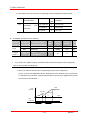
H26
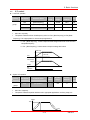
[Number of
0/10
Factory
Description
Auto Restart
Adjustable
defaults during run
This parameter sets the number of
0
O
restart tries after a fault occurs.
try]
Page
1015
Auto Restart is deactivated if the fault
outnumbers the restart tries.
This function is active when [drv] is
set to 1 or 2 {Run/Stop via control
terminal}.
Deactivated during active protection
function (OHT, LVT, EXT, HWT etc.)
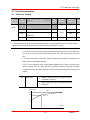
H27
H30
[Auto Restart
0/60
time]
[sec]
[Motor type
0.2/2.2
select]
H31
[Number of
2/12
parameter
sets
the
time
1.0
O
0.4
1)
X
4
X
3.0
X
between restart tries.
0.2
0.2 kW
0.4
0.4 kW
0.75
0.75 kW
1.5
1.5 kW
2.2
2.2 kW
This setting is displayed via rPM in
drive group.
motor poles]
H32
This
[Rated slip
0/10
frequency]
[Hz]
rpm P
fs fr
120
2)
Where, f s = Rated slip frequency
f r = Rated frequency
rpm = Motor nameplate RPM
P = Number of Motor poles
H33
[Motor rated
1.0/20
current]
[A]
Enter motor rated current on the
1.8
X
nameplate.
7-11
SINUS N
10-6
7. Function list
Function group 2
LED
Parameter
Min/Max
display
Name
Range
H34
[No Load
0.1/12
Motor
[A]
Description
Enter the current value detected
Factory
Adjustable
defaults
during run
0.9
X
72
X
0
X
10-6
3
O
10-
Page
10-6
when the motor is rotating in rated rpm
Current]
after the load connected to the motor
shaft is removed.
Enter the 50% of the rated current
value when it is difficult to measure H34
- [No Load Motor Current].
H36
H37
[Motor
50/100
efficiency]
[%]
[Load inertia
0/2
Enter the motor efficiency (see motor
nameplate).
rate]
Select one of the following according
to motor inertia.
0
Less than 10 times that of
motor inertia
1
About 10 times that of motor
inertia
2
More than 10 times that of
motor inertia
H39
[Carrier
1/15
frequency
[kHz]
This parameter affects the audible
sound of the motor, noise emission from
select]
16
the inverter, inverter temp, and leakage
current. If the value is set higher, the
inverter sound is quieter but the noise
from the inverter and leakage current
will become greater.
H40
[Control
0/3
mode select]
0
{Volts/frequency Control}
0
X
9-16
1
{Slip compensation control}
10-6
2
{PID Feedback control}
10-8
3
{Sensorless vector control}
1011
H41
[Auto tuning]
0/1
If this parameter is set to 1, it
0
X
automatically measures parameters of
10
the H42 and H43.
H42
[Stator
resistance
0/5.0[]
This is the value of the motor stator
-
X
resistance.
(Rs)]
7-12
10-
SINUS N
7. Function list
Function group 2
LED
Parameter
Min/Max
display
Name
Range
[Leakage
0/300.0
inductance
[mH]
H44
Description
This is leakage inductance of the
Factory
Adjustable
defaults during run
-
X
Page
stator and rotor of the motor.
(L)]
H45
Sensorless P
0/32767
P gain for Sensorless control
1000
O
I gain for Sensorless control
100
O
0
X
gain
H46
Sensorless I
gain
H50
[PID
3)
Feedback
0/1
0
Terminal I input (0 ~ 20 mA)
1
Terminal V1 input (0 ~ 10 V)
select]
3) : Set H40 to 2 (PID control) to display this parameter.
7-13
SINUS N
10-8
7. Function list
Function group 2
LED
Parameter
Min/Max
display
Name
Range
[P gain for
0/999.9
PID
[%]
H51
Description
This parameter sets the gains for the
Factory
Adjustable
defaults during run
Page
300.0
O
10-8
1.0
O
10-8
0.0
O
10-8
0.0
O
10-8
60.0
O
10-8
0
X
9-11
1
O
9-12
0
O
11-2
PID controller.
controller]
H52
[Integral time
0.1/32.0
for PID
[sec]
controller
(I gain)]
H53
Differential
0.0 /30.0
time for PID
[sec]
controller
(D gain)
H54
F gain for
0/999.9
PID
[%]
This is the Feed forward gain for the
PID controller.
controller
H55
[PID output
0/400
frequency
[Hz]
This parameter limits the amount of
the output frequency through the PID
limit]
control.
The value is settable within the range
of F21 – [Max frequency] and H23 –
[Start frequency].
H70
[Frequency
0/1
0
The Accel/Decel time is the time
Reference
that takes to reach the F21 –
for
[Max frequency] from 0 Hz.
Accel/Decel]
1
The Accel/Decel time is the time
that takes to reach a target
frequency from the run
frequency.
H71
[Accel/Decel
0/2
time scale]
H72
[Power on
0/13
0
Settable unit: 0.01 second.
1
Settable unit: 0.1 second.
2
Settable unit: 1 second.
display]
This parameter selects the parameter
to be displayed on the keypad when the
input power is first applied.
0
Frequency command
1
Accel time
7-14
SINUS N
7. Function list
Function group 2
LED
Parameter
Min/Max
display
Name
Range
H73
[Monitoring
0/2
Description
2
Decel time
3
Drive mode
4
Frequency mode
5
Multi-Step frequency 1
6
Multi-Step frequency 2
7
Multi-Step frequency 3
8
Output current
9
Motor rpm
10
Inverter DC link voltage
11
User display select
12
Fault display
13
Direction of motor rotation select
item select]
One of the following can be
Factory
Adjustable
defaults during run
Page
0
O
11-2
100
O
11-1
1.0
X
5.0
O
monitored via vOL - [User display
select].
H74
[Gain for
1/1000
Motor rpm
[%]
0
Output voltage [V]
1
Output power [kW]
2
Torque [kgf m]
This parameter is used to change the
motor speed display to rotating speed
display]
(r/min) or mechanical speed (m/mi).
120 f H 74
RPM
H 31 100
H79
[Software
0/10.0
version]
H81
H82
nd
This parameter displays the inverter
software version.
[2 motor
0/6000
Accel time]
[sec]
This parameter is active when the
selected terminal is ON after I20-I24 is
nd
nd
set to 12 {2 motor select}.
[2 motor
16
10.0
O
60.0
X
0
X
Decel time]
H83
nd
[2 motor
30/400
base
[Hz]
frequency]
H84
nd
[2 motor
0/2
V/F pattern]
7-15
10-
SINUS N
7. Function list
Function group 2
LED
Parameter
Min/Max
display
Name
Range
[2 motor
0/15 [%]
H85
nd
Description
Factory
Adjustable
defaults during run
5
X
5
X
Page
forward
torque boost]
H86
nd
[2 motor
reverse
1016
torque boost]
H87
nd
[2 motor
30/150
stall
[%]
150
X
150
O
100
O
1.8
X
0
X
prevention
level]
H88
nd
[2 motor
50/200
Electronic
[%]
thermal level
for 1 min]
H89
nd
[2 motor
Electronic
thermal level
for
continuous]
H90
nd
[2 motor
0.1/20
rated
[A]
current]
H93
[Parameter
0/5
initialize]
This parameter is used to initialize
parameters back to the factory default
1017
values.
0
-
1
All parameter groups are
initialized to factory default value.
2
Only Drive group is initialized.
3
Only Function group 1 is
initialized.
4
Only Function group 2 is
initialized.
5
H94
[Password
0/FFF
Only I/O group is initialized.
Password for H95-[Parameter lock].
0
O
register]
1018
7-16
SINUS N
7. Function list
Function group 2
LED
Parameter
Min/Max
display
Name
Range
H95
[Parameter
lock]
0/FFF
Description
This parameter is able to lock or unlock
Factory
Adjustable
defaults during run
0
O
parameters by typing password
Parameter change
enable
L (Lock)
Parameter change
disable
7-17
1019
registered in H94.
UL (Unlock)
Page
SINUS N
7. Function list
7.4
I/O group
LED
Parameter
Min/Max
display
name
range
I0
[Jump code]
0/63
Description
This parameter sets the code number to
Factory
Adjustable
defaults
during run
1
O
5-5
10
O
9-2
0
O
0.0
O
10
O
60.0
O
10
O
0
O
0.0
O
10
O
60.0
O
10
O
4
O
Page
jump
I1
[Filter time
0/9999
constant for
This is used to adjust the analog voltage
input signal via keypad potentiometer.
V0 input]
I2
I3
[V0 input Min
0/10
voltage]
[V]
[Frequency
0/400
Set the inverter output minimum
corresponding
[Hz]
frequency at minimum voltage of the V0
to I 2 ]
I4
I5
input.
[V0 input Max
0/10
Set the maximum voltage of the V0
voltage]
[V]
input.
[Frequency
0/400
Set the inverter output maximum
corresponding
[Hz]
frequency at maximum voltage of the V0
to I 4]
I6
Set the minimum voltage of the V0 input.
[Filter time
input.
0/9999
constant for
Set the input section’s internal filter
9-4
constant for V1 input.
V1 input]
I7
I8
[V1 input Min
0/10
voltage]
[V]
[Frequency
0/400
Set the inverter output minimum
corresponding
[Hz]
frequency at minimum voltage of the V1
to I 7]
I9
I10
input.
[V1 input max
0/10
Set the maximum voltage of the V1
voltage]
[V]
input.
[Frequency
0/400
Set the inverter output maximum
corresponding
[Hz]
frequency at maximum voltage of the V1
to I 9]
I11
Set the minimum voltage of the V1 input.
[Filter time
input.
0/9999
constant for I
Set the input section’s internal filter
constant for I input.
input]
I12
[I input
0/20
minimum
[mA]
Set the Minimum Current of I input.
current]
7-18
SINUS N
9-5
7. Function list
7.4
I/O group
LED
Parameter
Min/Max
display
name
range
I13
[Frequency
0/400
corresponding [Hz]
Description
Set the inverter output minimum
Factory
Adjustable
defaults during run
Page
0.0
O
20
O
60.0
O
0
O
12-7
0
O
9-8
1
O
2
O
frequency at minimum current of I input.
to I 12]
I14
I15
[I input max
0/20
current]
[mA]
[Frequency
0/400
corresponding [Hz]
Set the Maximum Current of I input.
Set the inverter output maximum
frequency at maximum current of I input.
to I 14]
I16
[Criteria for
0/2
Analog Input
0
Disabled
1
Less than half the value set in I
Signal loss]
2/7/12 entered
2
Below the value set in I 2/7/12
entered
I20
[Multi-function
0
Forward run command {FX}
1
Reverse run command {RX}
[Multi-function
2
Emergency Stop Trip {EST}
input terminal
3
Reset when a fault occurs {RST}.
[Multi-function
4
Jog operation command {JOG}
input terminal
5
Multi-Step frequency – Low
[Multi-function
6
Multi-Step frequency – Mid
input terminal
7
Multi-Step frequency – High
[Multi-function
8
Multi Accel/Decel – Low
input terminal
9
Multi Accel/Decel – Mid
P5 define]
10
Multi Accel/Decel – High
11
DC brake during stop
input terminal
0/24
P1 define]
I21
P2 define]
I22
10-3
9-7
P3 define]
I23
3
O
4
O
P4 define]
I24
12
2
nd
9-13
10-2
motor select
1016
13
-
14
-
7-19
SINUS N
7. Function list
7.4
I/O group
LED
Parameter
Min/Max
display
name
range
Description
15
Up-down
Frequency
operation
increase
Factory
Adjustable
defaults
during run
Page
10-4
command (UP)
16
Frequency
decrease
command
(DOWN)
17
3-wire operation
10-4
18
External trip: A Contact (EtA)
12-5
19
External trip: B Contact (EtB)
20
-
21
Exchange between PID operation
10-8
and V/F operation
22
Exchange between option and
Inverter
I25
I26
23
Analog Hold
24
Accel/Decel Disable
[Input terminal
BIT4
BIT3
BIT2
BIT1
BIT0
status display]
P5
P4
P3
P2
P1
BIT1
BIT0
30AC
MO
[Output
terminal
status display]
I27
[Filtering time 2/50
constant
for
If the value is set higher, the
-
-
11-3
11-3
15
O
30.0
O
25.0
O
20.0
O
15.0
O
response of the Input terminal is
Multi-function
getting slower.
Input terminal]
I30
I31
[Multi-Step
0/400
frequency 4]
[Hz]
It cannot be set greater than F21 –
[Max frequency].
[Multi-Step
frequency 5]
I32
[Multi-Step
frequency 6]
I33
[Multi-Step
frequency 7]
7-20
SINUS N
9-7
7. Function list
7.4
I/O group
LED
Parameter
Min/Max
display
name
range
I34
I35
[Multi-Accel
0/6000
time 1]
[sec]
Description
Factory
defaults during run
3.0
[Multi-Decel
Adjustable
O
Page
9-13
3.0
time 1]
I36
[Multi-Accel
4.0
9-13
time 2]
I37
[Multi-Decel
4.0
time 2]
I38
[Multi-Accel
5.0
time 3]
I39
[Multi-Decel
5.0
time 3]
I40
[Multi-Accel
6.0
time 4]
I41
[Multi-Decel
6.0
time 4]
I42
[Multi-Accel
7.0
time 5]
I43
[Multi-Decel
7.0
time 5]
I44
[Multi-Accel
8.0
time 6]
I45
[Multi-Decel
8.0
time 6]
I46
[Multi-Accel
9.0
time 7]
I47
[Multi-Decel
9.0
time 7]
I50
[Analog
output
0/3
item
10[V] Output
0
select]
1
Output
Max
frequency
frequency
Output
150 %
0
O
current
2
Output
282 V
voltage
7-21
SINUS N
11-5
7. Function list
7.4
I/O group
LED
Parameter
Min/Max
display
name
range
Description
3
DC
Factory
Adjustable
defaults
during run
100
O
30.0
O
10.0
O
12
O
Page
link DC 400V
voltage
I51
[Analog
output
10/200
level [%]
adjustment]
I52
I53
[Frequency
0/400
detection
[Hz]
This parameter is used when I54 –
or I55 – [Multi-function relay select] are
[Frequency
set to 0-4.
It cannot be set greater than F21 –
[Max frequency].
bandwidth]
[Multi-function
0/17
0
output
terminal
11-6
[Multi-function output terminal select]
level]
detection
I54
FDT-1
FDT-2
11-6
11-6
1
select]
I55
[Multi-function
2
FDT-3
relay select]
3
FDT-4
11-8
4
FDT-5
11-9
5
Overload {OL}
11-9
6
Inverter Overload {IOL}
7
Motor stall {STALL}
8
Over voltage trip {OV}
9
Low voltage trip {LV}
10
Inverter
17
cooling
fan
11-8
overheat
{OH}
11
Command loss
12
During run
11-
13
During stop
10
14
During constant run
15
During speed searching
16
Wait time for run signal input
17
Fault relay output
7-22
SINUS N
7. Function list
7.4
I/O group
LED
Parameter
Min/Max
display
name
range
I56
[Fault
relay 0/7
output]
When
When
setting
the
I61
I62
[Inverter
1/32
When the
voltage
[Number
trip
than low
auto voltage
trip
try]
occurs
Bit 2
Bit 1
Bit 0
0
-
-
-
1
-
-
2
-
-
3
-
4
-
-
5
-
6
-
7
This parameter is set when the
inverter uses RS485 communication
number]
option.
[Drive
select
0/4
mode 0/2
1200 bps
1
2400 bps
2
4800 bps
3
9600 bps
4
19200 bps
after
loss
Select the Baud rate of the RS485
0
O
1
O
3
O
0
O
It is used when frequency command
is given via V1 and I terminal or
of
communication option.
frequency
0
Continuous operation
command]
1
Free Run stop (Coast to
stop)
2
Decel to stop
7-23
11-6
occurs
station
[Baud rate]
2
Page
trip low
restart
Adjustable
defaults during run
the H26– other
of
I60
Factory
Description
SINUS N
12-7
7. Function list
7.4
I/O group
LED
Parameter
Min/Max
display
name
range
I63
[Wait
time 0.1/12
Description
This is the time inverter determines
after loss of [sec]
whether there is the input frequency
frequency
command or not. If there is no
command
frequency command input during this
Factory
Adjustable
defaults
during run
1.0
-
time, inverter starts operation via the
mode selected at I62.
Notes:
7-24
SINUS N
Page
8. Control block diagram
Drive mode
Accel/Decel
V/F
control
PWM
Motor
Control block diagram
Frequency
setting
8
8-1
SINUS N
8-2
P5
P4
P3
P2
P1
I
V1
VR : Potentiometer
Digital
input filter
I/O group
I27
Analog
input filter
I/O group
I 1, 6, 11
Max/Min
frequency
Functi
group
on
1
F21
F23
I31
I32
I33
St2
St3
I/O group
I30
I/O group
St1
0,1
+
Step 0-7
I/O input
override
17
3-Wire
operation
I/O group
I20 ~ I24
Step freq.setting
FX/RX run command
setting via Multi-function
terminal
I/O group
I20 ~ I24
5,6,7
I/O group
I20 ~ I24
Multi-step operation via
Multi-function terminal
Analog
input scale
I/O group
I 2 ~ I15
15, 16
LED
I20 ~ I24
I/O group
7
0
1,2
0
1
2
drv
Drive group
Run command
setting
VR + V1
VR:potentiometer
V1 : 0 ~ 10V
I : 0 ~ 20mA
VR + I
V1 + I
Keypad setting 2
Keypad setting 1
6
2 1
Up/Down operation
7
3
4
5
6
0
1
2
5
4
3
Drive group
Frq
Freq. setting
Step 0
1
2
0
FX/RX run enable
Forward run disable
Reverse run enable
Func.group1
F1
FX/RX Run Disable
Func.group1
F20
Jog frequency
P1 ~ P5
4
I/O group
I20 ~ I24
Jog operation
Run
command
Frequency
setting
8.1
LED
8. Control block diagram
Frequency and Drive mode setting
SINUS N
P5
P4
P3
P2
P1
5,6,7
I20 ~ I24
I/O group
I/O group
I27
Multi-Accel/Decel
time select
Digital input filter
8-3
SINUS N
F29
F28
Torque
boost value
Func. group
F31~F38
Func. group
User V/F
Freq., Voltage
I34 ~ I47
1st-7th Accel/
Decel time
I/O group
0
1~7
Automatic
Manual
User V/F
Square
Linear
P1 ~ P5
1
0
F27
Func. group
Torque boost
select
2
1
0
F2, F3
Func. group
V/F pattern
Frequency
setting
1
0
H70
Reference freq. for
Accel/Decel
Func. group1
F21
DEC
Func. group1
ACC
Max freq.
+
F2, F3
Linear
1 S-curve
0
Accel/Decel
pattern
Func. group1
Run
command
F39
I/O group
Output voltage
adjustment
F8 ~ F11
Func. group1
DC brake freq.
voltage, time
Stop
2
1
0
F23
F22
I/O group
Base/start freq.
FreeRun Stop
DC brake
F4
Func. group1
Stop method select
Dwell operation
PWM
I/O group
F25
F26
H7
H8
DC brake start freq.
Operation
F8 ~ F11
Freq. high/low limit
Func. group1
Dwell freq. & time
8.2
Accel/Decel
time
Drive group
DC brake voltage
& time
Func. group1
8. Control block diagram
Accel/Decel setting and V/F control
9. Basic functions
9
Basic Functions
Frequency mode
9.1
Digital Frequency setting via Keypad 1
Group
LED Display
Parameter Name
Set
Min/Max
Factory
Value
Range
Defaults
Drive
0.0
[Frequency Command]
-
0/400
0.0
group
Frq
[Frequency mode]
0
0/8
0
Unit
Hz
Run frequency is settable in 0.0 - [Frequency Command].
Set Frq – [Frequency mode] to 0 {Frequency setting via Keypad 1}.
Set the desired frequency in 0.0 and press the Prog/Ent () key to enter the value into memory.
The value is settable not greater than F21 – [Max frequency].
Digital Frequency setting via Keypad 2
Group
LED Display
Parameter Name
Set
Min/Max
Factory
Value
Range
Defaults
Drive
0.0
[Frequency Command]
-
0/400
0.0
group
Frq
[Frequency mode]
1
0/8
0
Unit
Hz
Run frequency is settable in 0.0 - [Frequency Command].
Set Frq – [Frequency mode] to 1{Frequency setting via Keypad 2}.
In 0.0, frequency is changed upon pressing the Up ()/Down () key. It is seleted to use the
Up/Down key as potentiometer on keypad.
The value is settable not greater than F21 – [Max frequency].
9-1
SINUS N
9. Basic functions
Analog Frequency setting via Potentiometer (V0) on the Keypad
Used to prevent fluctuations in analog input signals caused by noise
Group
LED Display
Parameter Name
Set
Min/Max
Factory
Value
Range
Defaults
Unit
Drive
0.0
[Frequency Command]
-
-
-
group
Frq
[Frequency Mode]
2
0/8
0
10
0/9999
10
-
0/10
0
V
-
0/400
0.0
Hz
-
0/10
10
V
-
0/400
60.0
Hz
I/O
group
I1
I2
I3
I4
I5
[Filter time constant for V0
input]
[V0 input minimum voltage]
[Frequency corresponding to
I2]
[V0 input max voltage]
[Frequency corresponding to
I4]
Set Frq – [Frequency Mode] to 2.
The set frequency can be monitored in 0.0- [Frequency Command].
Hz
I 1 : [Filtering time constant for V0 input]
Effective for eliminating noise in the frequency setting circuit.
Increase the filter time constant if steady operation cannot be performed due to noise. A larger
setting results in slower response (t gets longer).
V0 input
Set f req
t
I 2 - I 5 : [Min/Max input voltage and corresponding frequency setting]
The corresponding frequency to V0 input voltage is settable.
Example: When setting I 2 - [V0 input minimum voltage] = 2V, I 3- [Frequency corresponding
to I 2]= 10Hz, I 4 - [V0 input max voltage] = 8V and I 5 - [Frequency corresponding to I 4]=
50Hz, the following figure is shown.
Freq.
setting
I5
I3
50Hz
10Hz
2V
8V
I2
V0 input
I4
9-2
SINUS N
9. Basic functions
9-3
SINUS N
9. Basic functions
Analog Frequency setting via Voltage analog input (0-10V) or potentiometer on the VR terminal
Group
LED Display
Parameter Name
Set
Min/Max
Factory
Value
Range
Defaults
Drive
0.0
[Frequency command]
-
-
-
group
Frq
[Frequency mode]
3
0/8
0
10
0/9999
10
I/O
I6
group
[Filtering time constant for V1
input]
Unit
Hz
I7
[V1 input minimum voltage]
-
0/10
0
V
I8
[Frequency corresponding to I 7]
-
0/400
0.0
Hz
I9
[V1 input max voltage]
-
0/10
10
V
I10
[Frequency corresponding to I 9]
-
0/400
60.0
Hz
Select Frq -[Frequency Mode] to 3 {Frequency setting via V1 terminal}.
The 0-10V input can be directly applied from an external controller or a potentiometer (between VR
and CM terminals).
Wire the terminal as shown below and refer to page 9-2 for I 6 - I10.
VR
V1
V1
CM
CM
Analog Voltage Input (0-10V)
When connecting potentiometer to
terminals VR and CM
Frequency Setting via Analog Current Input (0-20mA)
Group
LED Display
Parameter Name
Set
Min/Max
Factory
Value
Range
Defaults
Unit
Drive
0.0
[Frequency Command]
-
-
-
group
Frq
[Frequency Mode]
4
0/8
0
I/O
I11
[Filtering time constant for I input]
10
0/9999
10
group
I12
[I input minimum current]
-
0/20
4
mA
I13
[Frequency corresponding to I 12]
-
0/400
0.0
Hz
I14
[I input max current]
-
0/20
20
mA
I15
[Frequency corresponding to I 14]
-
0/400
60.0
Hz
Select Frq – [Frequency Mode] to 4 {Current Analog Input (0-20mA)}.
Frequency is set via 0-20mA input between I and CM terminals.
See page 9-2 for I11-I15.
9-4
Hz
SINUS N
9. Basic functions
Frequency setting via Potentiometer on the keypad + Current Analog input (0-20mA)
Group
LED Display
Parameter Name
Set
Min/Max
Factory
Value
Range
Defaults
Drive
0.0
[Frequency Command]
-
-
-
group
Frq
[Frequency Mode]
5
0/8
0
Unit
Hz
Select Frq – [Frequency Mode] to 5 {Potentiometer on the keypad and Current Analog input (020mA)}.
Override function is provided via Main speed and Auxiliary speed adjustment.
Related code : I 1 - I 5, I 11- I 15
When main speed is set via potentiometer and Auxiliary speed via 0-20mA analog input, the
override function is set as below.
Group
I/O group
Code
Set
Parameter Name
value
Units
I2
[V0 input minimum voltage]
0
V
I3
[Frequency corresponding to I 2]
0
Hz
I4
[V0 input max voltage]
10
V
I5
[Frequency corresponding to I 4]
60.0
Hz
I 12
[I input minimum current]
4
mA
I 13
[Frequency corresponding to I 12]
0
Hz
I 14
[I input max current]
20
mA
I 15
[Frequency corresponding to I 14]
5.0
Hz
After the above setting is made, if 5V is set via potentiometer and 10mA is applied via I terminal, 32.5Hz is
output
Frequency setting via 0-10V + 0-20mA input
Group
LED Display
Parameter Name
Set
Min/Max
Factory
Value
Range
Defaults
Drive
0.0
[Frequency Command]
-
-
-
group
Frq
[Frequency Mode]
6
0/8
0
Unit
Hz
Set Frq – [Frequency Mode] to 6 {V1 + I terminal input}.
Related code : I 6 - I 10, I 11 - I 15
Refer to the Frequency setting via Potentiometer on the keypad + Current Analog input (0-20mA)
for the setting.
9-5
SINUS N
9. Basic functions
Frequency setting via Potentiometer on the keypad + 0-10V input
Group
LED Display
Parameter Name
Set
Min/Max
Factory
Value
Range
Defaults
Drive
0.0
[Frequency Command]
-
-
-
group
Frq
[Frequency Mode]
7
0/8
0
Unit
Hz
Set Frq – [Frequency Mode] to 7 {Potentiometer on the keypad + 0-10V input}.
Relative code: I 1 - I 5, I6 - I10
Refer to P 9-4 Frequency setting via potentiometer on the Keypad + 0-20mA input for the setting.
Analog Hold
Group
Drive
group
I/O
group
LED Display
Frq
I20
Parameter Name
[Frequency Mode]
[Multi-function
terminal P1 define]
~
I24
input
Set
Min/Max
Factory
Value
Range
Defaults
2/7
0/8
0
-
0/24
Unit
0
~
[Multi-function
input
Terminal P5 Define]
23
4
This setting becomes activated when Frq – [Frequency Mode] is set to 2-7.
Set one of the Multi-function input terminals to 23 to activate Analog Hold operation.
When I24 –[Multi-function input terminal P5 define] is set to 23,
Freq. setting
Freq.
P5
Run
command
9-6
SINUS N
9. Basic functions
Multi-Step frequency setting
9.2
Group
LED Display
Drive
group
I/O
group
Parameter Name
Set
Value
Min/Max
Range
Factory
Defaults
Unit
5.0
0/400
0.0
Hz
0/8
0
-
0.0
[Frequency command]
Frq
[Frq mode]
0
St1
[Multi-Step frequency 1]
-
St2
[Multi-Step frequency 2]
-
St3
[Multi-Step frequency 3]
-
30.0
I22
[Multi-function
input
terminal P3 define]
5
2
-
I23
[Multi-function
input
terminal P4 define]
6
3
-
I24
[Multi-function
input
terminal P5 define]
7
4
-
I30
[Multi-Step frequency 4]
-
30.0
I31
[Multi-Step frequency 5]
-
10.0
0/400
Hz
20.0
0/24
25.0
0/400
Hz
I32
[Multi-Step frequency 6]
-
20.0
I33
[Multi-Step frequency 7]
-
15.0
Select a terminal to give Multi-step frequency command among P1-P5 terminals.
If terminals P3-P5 are selected for this setting, set I22-I24 to 5-7 to give Multi-step frequency
command.
Multi-step frequency 0 is settable using Frq – [Frequency mode] and 0.0 – [Frequency command].
Multi-step frequency 1-3 are set at St1-St3 in Drive group, while Step frequency 4-7 are set at I30I33 in I/O group.
Step
FX or
freq
RX
P5
P4
Step 2
P3
Step 1
Step 0
0
-
-
-
1
-
-
2
-
-
3
-
4
-
-
P4
5
-
P5
6
-
FX
7
Step 3
Step 0
Frequency
Step 4
Step 5
Step 7
Step 6
P3
RX
9-7
SINUS N
9. Basic functions
Run Command setting
9.3
Run via the Run and STOP/RST key
Group
LED Display
Drive
group
Parameter Name
drv
[Drive mode]
(Run/Stop mode)
drC
[Direction
of
rotation select]
motor
Set
Value
Min/Max
Range
Factory
Defaults
0
0/3
1
-
F/r
F
Unit
Set drv – [Drive mode] to 0.
Motor starts to accelerate by pressing the Run key while run frequency is set. Motor decelerates to
stop by pressing the STOP/RST key.
Selecting rotation direction is available at drC - [Direction of motor rotation select] when run
command is issued via Run key on keypad.
drC
[Direction of motor
F
Forward
rotation select]
R
Reverse
FX : Counter clockwise
Group
LED Display
Run command setting 1 via FX and RX terminals
Parameter Name
Drive
group
drv
[Drive mode]
(Run/Stop mode)
I/O
group
I20
[Multi-function
terminal P1 define]
input
I21
[Multi-function
terminal P2 define]
input
Set
Value
Min/Max
Range
Factory
Defaults
1
0/3
1
0
0/24
0
1
0/24
1
Unit
Set drv – [Drive mode] to 1.
Set I20 and I21 to 0 and 1 to use P1 and P2 as FX and RX terminals.
“FX” is Forward run command and “RX” Reverse run.
Operation will stop when both FX and RX terminals are turned ON or OFF.
Frequency
FX
RX
9-8
SINUS N
9. Basic functions
Run command setting 2 at FX and RX terminals
Group
Drive
group
I/O
group
LED Display
drv
I20
I21
Parameter Name
[Drive mode]
(Run/Stop mode)
[Multi-function
input
terminal P1 define]
[Multi-function
input
terminal P2 define]
Set
Min/Max
Factory
Value
Range
Defaults
2
0/3
1
0
0/24
0
1
0/24
1
Unit
Set the drv to 2.
Set I20 and I21 to 0 and 1 to use P1 and P2 as FX and RX terminals.
FX: Run command setting. Motor runs in forward direction when RX terminal (P2) is OFF.
RX: Direction of motor rotation select. Motor runs in reverse direction when RX terminal (P2) is ON.
Frequency
FX
RX
FX/RX Run Disable
Group
Drive
group
Function
group 1
LED Display
drC
F1
Parameter Name
[Direction
of
motor
rotation select]
[Forward/Reverse
run
disable]
Set
Min/Max
Factory
Value
Range
Defaults
-
F/r
F
-
0/2
0
Unit
Select the direction of motor rotation.
0 : Forward and Reverse run enable
1 : Forward run disable
2 : Reverse run disable
9-9
SINUS N
9. Basic functions
Power On Start select
Group
LED Display
Parameter Name
Drive
group
drv
[Drive mode]
(Run/Stop mode)
Function
group 2
H20
[Power On Start select]
Set
Value
Min/Max
Range
Factory
Defaults
1, 2
0/3
1
1
0/1
0
Unit
Set H20 to 1.
When AC input power is applied to the inverter with drv set to 1 or 2 {Run via control terminal},
motor starts acceleration.
This parameter is inactive when the drv is set to 0 {Run via keypad}.
CAUTION
Particular attention must be directed to this function due to potential hazard as motor starts to run
suddenly upon applying AC input power.
Input voltage
Frequency
Run
command
When H20 is 0
When H20 is 1
Restart after fault reset
Group
LED display
Parametern name
Drive
group
Drv
[Drive mode]
(Run/Stop mode)
Function
group 2
H21
[Restart after fault reset]
Set
value
Min/Max
range
Factory
defaults
1, 2
0/3
1
1
0/1
0
Unit
Set H21 to 1.
Motor starts acceleration if drv is set to 1 or 2 and the selected terminal is ON when a fault is
cleared.
This function is inactive when the drv is set to 0 {Run via the Keypad}.
CAUTION
Particular attention must be directed to this function due to potential hazard as motor
starts to run suddenly after the fault is cleared.
9-10
SINUS N
9. Basic functions
Frequency
Reset
Run
command
When H21 is 0
Accel/Decel time and unit setting
9.4
When H21 is 1
Accel/Decel time setting based on Max frequency
Group
LED Display
Parameter Name
Set
Min/Max
Factory
Value
Range
Defaults
Unit
Drive
ACC
[Accel time]
-
0/6000
5.0
sec
group
dEC
[Decel time]
-
0/6000
10.0
sec
F21
[Max frequency]
-
0/400
60.0
Hz
0
0/1
0
-
0/2
1
Function
group 1
Function
H70
group 2
H71
[Frequency
Reference
for Accel/Decel]
[Accel/Decel Time setting
unit]
Set the desired Accel/Decel time at ACC/dEC in Drive group.
If H70 is set to 0 {Max frequency}, Accel/Decel time is the time that takes to reach the max freq
from 0 Hz.
Desired Accel/Decel time unit is settable at the H71.
Accel/Decel time is set based on F21 – [Max frequency]. For instance, if F21 is set to 60Hz,
Accel/Decel time 5 sec, and run frequency 30Hz, time to reach 30Hz would be 2.5 sec.
Max. freq.
60Hz
Run Freq.
30Hz
Run
command
Accel time
Decel time
9-11
SINUS N
9. Basic functions
More precise time unit can be set corresponding to load characteristics as shown below.
Code
Setting range
Parameter Name
value
H71
[Accel/Decel
Description
0.01~600.00
0
Unit: 0.01 sec.
0.1~6000.0
1
Unit: 0.1 sec.
1~60000
2
Unit: 1 sec.
Time
setting unit]
Set
Accel/Decel time based on Run frequency
Group
LED display
Parameter name
Set
Min/Max
Factory
value
range
defaults
Unit
Drive
ACC
[Accel time]
-
0/6000
5.0
sec
group
dEC
[Decel time]
-
0/6000
10.0
sec
1
0/1
0
Function
group 2
H70
[Frequency
reference
for Accel/Decel]
Accel/Decel time is set at the ACC/dEC.
If you set H70 to 1 {Delta frequency}, Accel/Decel time is the time that takes to reach a target freq
from run freq (Currently operating freq.).
When H70 and Accel time are set to 1 {Delta frequency} and 5 sec, respectively,
(A zone: run freq 10 Hz applied first, B zone: Operating via 10 Hz, different run freq is not issued
C: 30Hz Run freq (in this case, Target freq) issued while 10 Hz run freq is applied. But the preset
accel time 5 sec is maintained. )
30Hz
Freq.
command
(Target freq.)
(Run freq.)
10Hz
A
B
5
(Delta freq.)
C
7
Time
12
[sec]
Run
command
5 sec
5 sec
9-12
SINUS N
9. Basic functions
Multi-Accel/Decel time setting via Multi-function terminals
Group
LED Display
Parameter Name
Set
Min/Max
Factory
Value
Range
Defaults
Unit
Drive
ACC
[Accel time]
-
0/6000
5.0
Sec
group
dEC
[Decel time]
-
0/6000
10.0
Sec
I/O group
I20
I21
I22
I23
I24
I34
[Multi-function
terminal P1 define]
[Multi-function
input
terminal P2 define]
[Multi-function
input
terminal P3 define]
[Multi-function
input
terminal P4 define]
[Multi-function
input
terminal P5 define]
[Multi-Accel time 1]
~
I47
input
0
0/24
0
1
1
8
2
9
3
10
4
-
0/6000
Sec
3.0
~
[Multi-Decel time 7]
-
9.0
Set I22, I23, I24 to 8, 9, 10 if you want to set Multi - Accel/Decel time via P3-P5 terminals.
Multi-Accel/Decel time 0 is settable at ACC and dEC.
Multi-Accel/Decel time 1-7 is settable at I34-I47.
Accel
time 2
Accel
time 1
Accel
Time 0
Frequency
Accel
time 3
Decel
time 4
Decel
time 5
Decel
time 6
Decel
time 7
MultiAccel/Decel
P5
P4
P3
0
-
-
-
1
-
-
2
-
-
3
-
4
-
-
5
-
6
-
7
time
P3
P4
P5
FX
9-13
SINUS N
9. Basic functions
Accel/Decel pattern setting
Min/Max
Group
LED display
Function
F2
[Accel pattern]
0
Linear
group 1
F3
[Decel pattern]
1
S-curve
H17
H18
Parameter name
S-Curve
Set value
range
0
accel/decel
start side
Unit
40
%
40
%
1~100
S-Curve
accel/decel
end side
Accel/Decel pattern is settable at F2 and F3.
Linear : This is a general pattern for constant torque applications
S-curve : This curve allows the motor to accelerate and decelerate smoothly.
Appropriate applications: Elevator door, lifts..
Caution :
For S-curve, the actual Accel/Decel time takes longer than the time set by user.
Freq.
Run
command
Accel time
Decel time
Accel/Decel
1/2 of
Ref. Freq.
Accel/Decel Ref.
Freq
Freq
H17
H18
Accel
Accel
Starting Ending
H17
Decel
Starting
9-14
H18
Decel
Ending
SINUS N
9. Basic functions
Note that setting Frequency Ref for Accel/decel (H70) is set to Max Freq and target freq is set
below Max freq. the shape of S-curve may be distorted.
Accel/decel Ref
Freq (H70)
Note: If set target freqis
below
Target Freq
Max
freq,
the
curve will not be shown
completely.
Freq
H17
H18
H17
H18
Accel/Decel Disable
Group
I/O group
LED display
I20
Parameter name
[Multi-function
terminal P1 define]
~
I24
input
Set
Min/Max
Factory
value
range
defaults
0/24
-
Unit
0
~
[Multi-function input
terminal P5 define]
24
4
Select one terminal of I20-24 to define Accel/Decel disable.
For example, if P5 is selected, set I24 to 24 to activate this function.
Freq.
P5
Run
command
ON
ON
ON
9-15
SINUS N
9. Basic functions
V/F control
9.5
Linear V/F operation
Set
Min/Max
Factory
Value
Range
Defaults
[Base frequency]
-
30/400
60.0
Hz
F23
[Start frequency]
-
0/10.0
0.5
Hz
F30
[V/F pattern]
0
0/2
0
Group
LED Display
Parameter Name
Function
F22
group 1
Set F30 to 0 {Linear}.
This pattern maintains a linear Volts/frequency ratio from F23 - [Start frequency] to F22- [Base
Unit
frequency]. This is appropriate for constant torque applications.
F22 – [Base frequency] : Inverter outputs its rated voltage at this level. Enter the motor
nameplate frequency.
F23 – [Start frequency] : Inverter starts to output its voltage at this level.
Base freq.
Start freq.
Freq.
Inverter rated
voltage
Voltage
Run
command
Square V/F operation
Group
Function
group 1
LED Display
Parameter Name
F30
[V/F pattern]
Set
Min/Max
Factory
Value
Range
Defaults
1
0/2
0
Set F30 to 1{Square}.
This pattern maintains squared volts/hertz ratio. Appropriate applications are fans, pumps, etc.
Unit
Voltage
100%
Freq.
Base freq.
9-16
SINUS N
9. Basic functions
User V/F pattern
Group
Function
group 1
LED
display
Parametername
Min/Max
range
Factory
defaults
Unit
F30
[V/F pattern]
2
0/2
0
F31
[User V/F frequency 1]
-
0/400
15.0
Hz
-
0/100
100
%
~
F38
Set
value
~
[User V/F voltage 4]
Select F30 to 2 {User V/F}.
User can adjust the Volt/Frequency ratio according to V/F pattern of specialized motors and load
characteristics.
CAUTION
In case of using a standard induction motor, if this value is set much higher than linear V/F pattern,
it could result in torque shortage or motor overheating due to over-energizing.
When User V/F pattern is active, F28 - [Torque Boost in forward direction] and F29 - [Torque Boost
in reverse direction] are deactivated.
Voltage
100%
F38
F36
Linear
V/F
F34
F32
Freq.
Start
freq.
F31
F33
F37 Base
freq.
F35
Output voltage adjustment
Group
Function
group 1
LED Display
F39
Parameter Name
Set
Min/Max
Factory
Value
Range
Defaults
-
40/110
100
[Output voltage
adjustment]
Unit
%
This function is used to adjust the output voltage of the inverter. This is useful when you use a
motor that has a rated voltage lower than the input voltage.
Voltage
100% setting
100%
70% setting
70%
Freq.
Base freq.
9-17
SINUS N
9. Basic functions
Manual Torque Boost
Group
LED display
Function
group 1
F27
[Torque boost select]
F28
[Torque boost in forward
direction]
F29
[Torque boost in reverse
direction]
Parameter name
Set
Value
Min/Max
range
Factory
defaults
0
0/1
0
-
0/15
5
Unit
%
Set F27 to 0 {Manual torque boost}.
The values of [Torque boost in forward/reverse direction] are set separately in F28 and F29.
CAUTION
If the boost value is set much higher than required, it may cause motor overheating due to overenergizing.
Voltage
100%
No torque boost
FX torque
boost
Time
RX torque
boost
FX
RX
Auto Torque Boost
Group
LED Display
Function
Parameter Name
Set
Min/Max
Factory
Value
Range
Defaults
F27
[Torque boost select]
1
0/1
0
Function
H34
[No Load Motor Current]
-
0.1/12
-
group 2
H41
[Auto tuning]
0
0/1
0
H42
[Stator resistance (Rs)]
-
0/5.0
-
group 1
Unit
A
Before Auto Torque Boost setting, H34 and H42 should be set correctly (See page 10-6, 10-8).
Set F27 to 1 {Auto torque boost}.
The inverter automatically boosts the output voltage by calculating torque boost value using motor
parameters.
9-18
SINUS N
9. Basic functions
Stop mode select
9.6
Decel to stop
Group
LED Display
Function
F4
group 1
Parameter Name
[Stop mode select]
Set F30 to 0 {Decel to stop}.
The inverter decelerates to 0Hz for the preset time.
Set
Min/Max
Factory
Value
Range
Defaults
0
0/2
0
Set
Min/Max
Factory
Value
Range
Defaults
1
0/2
0
Set
Min/Max
Factory
Value
Range
Defaults
2
0/2
0
Unit
Freq.
Run
command
Decel time
DC brake to stop
Group
LED Display
Function
F4
group 1
Parameter Name
[Stop mode select]
Unit
Set F30 to 1 {DC brake to stop} (See page 10-1 for more).
Free run to stop
Group
Function
group 1
LED Display
F4
Parameter Name
[Stop mode select]
Set F30 to 2 {Free run to stop}.
The inverter turns off the output frequency and voltage when the run command is OFF.
Unit
Freq. Voltage
Run command
9-19
SINUS N
9. Basic functions
Frequency limit setting
9.7
Frequency limit setting based on Max and start frequency
Group
LED display
Function
F21
group 1
F23
Set
Min/Max
Factory
value
range
defaults
[Max frequency]
-
0/400
60.0
Hz
[Start frequency]
-
0/10
0.5
Hz
Parameter name
Unit
Max frequency: Frequency high limit except for F22 [Base frequency]. Any frequency cannot be set
above [Max frequency].
Start frequency: Frequency low limit. If a frequency is set lower than this, 0.00 is automatically set.
Run frequency limit based on frequency High/Low limit
Group
LED Display
Function
F24
group 1
Parameter Name
[Frequency
High/Low
limit select]
Set
Min/Max
Factory
Value
Range
Defaults
1
0/1
0
Unit
F25
[Frequency high limit]
-
0/400
60.0
Hz
F26
[Frequency low limit]
-
0/400
0.5
Hz
Set F24 to 1.
Active run frequency can be set within the range set in F25 and F26.
When frequency setting is done via Analog input (voltage or current input), the inverter
operates within the range of high and low limit frequency as shown below.
This setting is also valid when frequency setting is done via keypad.
Freq.
When freq. limit is not selected
Max freq.
High limit
freq.
Low limit
freq.
10V V1(Voltage input)
0
20mA I (Current input)
9-20
SINUS N
9. Basic functions
Skip frequency
Group
LED display
Parameter name
Function
H10
[Skip frequency select]
group 2
H11
[Skip frequency low limit
1]
~
H16
Set
Min/Max
Factory
value
range
defaults
1
0/1
0
-
0/400
10.0
Hz
-
0/400
35.0
Hz
Unit
~
[Skip frequency high limit
3]
Set H10 to 1.
Run frequency setting is not available within the skip frequency range of H11-H16.
Skip frequency is settable within the range of F21 – [Max frequency] and F23 – [Start frequency].
Freq.
H16
H15
H14
H13
H12
H11
10V V1(Voltage input)
20mA I (Current input)
0
Run
command
Freq. Up setting
Freq. Down
setting
When it is desired to avoid resonance attributable to the natural frequency of a mechanical
system, these parameters allow resonant frequencies to be skipped. Three different areas of [Skip
frequency High/Low limit] can be set with the skip frequencies set to either the top or bottom point of
each area. However, during acceleration or deceleration, the run frequency within the set area is valid.
In the case of increasing frequency setting as shown above, if frequency set value (Analog
setting via voltage, current or digital setting via keypad) is within the range of Skip frequency, it
maintains Skip frequency low limit value. If the set value is outside the range, it increases the
frequency.
In the case of decreasing frequency setting, if frequency set value (Analog setting via
voltage, current or Digital setting via keypad) is within the range of Skip frequency, it maintains Skip
frequency high limit value. If the set value is outside the range, it decreases the frequency.
9-21
SINUS N
9. Basic functions
9-22
SINUS N
10. Advanced functions
10 Advanced functions
10.1
DC brake
Stop mode via DC brake
Group
LED Display
Function
F4
group 1
F8
Parameter Name
Set
Min/Max
Factory
value
Range
Defaults
1
0/2
0
-
0/60
5.0
Hz
[Stop mode select]
[DC
Brake
start
frequency]
Unit
F9
[DC Brake wait time]
-
0/60
1.0
sec
F10
[DC Brake voltage]
-
0/200
50
%
F11
[DC Brake time]
-
0/60
1.0
sec
Set F4 - [Stop mode select] to 1.
F 8 : The frequency at which the DC brake will become active.
F 9 : Inverter will wait for this time after F8 - [DC Brake start frequency] before applying F10 - [DC
Brake voltage].
F10 : It sets the level as a percent of H33 – [Motor rated current].
F11 : It sets the time that F10 - [DC Brake voltage] is applied to the motor after F 9 - [DC Brake wait
time].
Caution:
If excessive DC Brake voltage is set or DC Brake time is set too long, it may cause motor overheating
and damage to the motor.
F9
Freq.
F11
F8
Voltage
Current
F10
Run
command
Setting F10 or F11 to 0 will disable DC brake.
F 9 – [DC Brake Wait time] : When load inertia is great or F 8 – [DC Brake Start
Frequency] is high, Over current trip may occur. It can be prevented via F9.
10-1
SINUS N
10. Advanced functions
Starting DC brake
Set
Min/Max
Factory
value
Range
Defaults
[DC Brake start voltage]
-
0/200
50
%
[DC Brake start time]
-
0/60
0
sec
Group
LED Display
Parameter Name
Function
F12
group 1
F13
F12 : It sets the level as a percent of H33 – [Motor rated current].
F13 : Motor accelerates after DC voltage is applied for the set time.
Unit
Caution :
If excessive DC Brake voltage is set or DC Brake time is set too long, it may cause motor overheating
and damage to the motor.
Freq.
F13
t
Voltage
F12
Run command
Setting F12 or F13 to 0 will disable Starting DC brake.
t : After F13 - [DC Brake start time], the frequency is increasing after DC voltage is
applied until the time t. In this case, DC Brake start time may be longer than the set value.
DC brake at a stop
Group
LED Display
Parameter Name
F12
[DC Brake start voltage]
Function
group 1
I/O
group
I22
[Multi-function
input
terminal P3 define]
Set
Min/Max
Factory
value
Range
Defaults
-
0/200
50
11
0/24
2
F12 : Set as a percent of H33 – [Motor rated current].
Select a terminal to issue a command of DC brake during stop among P1 through P5.
If P3 terminal is set for this function, set 22 to 11 {DC brake during stop}.
Unit
%
Caution :
If excessive DC Brake voltage is set or DC Brake time is set too long, it may cause motor overheating
and damage to the motor.
10-2
SINUS N
10. Advanced functions
Voltage
F12
P3
Run
command
10.2
Jog operation
Group
Function
group 1
I/O group
LED display
F20
I22
Parameter name
Jog frequency
[Multi-function
input
terminal P3 define]
Set
Min/Max
Factory
value
range
defaults
-
0/400
10.0
4
0/24
2
Unit
Set the desired jog frequency in F20.
Select the terminal among the Multi-function input terminal P1 through P5 to use for this
Hz
setting.
If P3 is set for Jog operation, set I22 to 4 {Jog}.
Jog frequency can be set within the range of F21 - [Max frequency] and F22 – [Start frequency].
P1
FX : I20 = 0
P3
JOG : I22=4
CM
F20
Frequency
P3 (JOG)
Run
Command (FX)
Jog operation overrides all other operations except Dwell operation. Therefore, if Jog
frequency command is entered in the middle of Multi-Step, Up-Down or 3-wire operation,
operation is executed at Jog frequency.
10-3
SINUS N
10. Advanced functions
10.3
Up-Down operation
Group
I/O group
LED display
I20
Parameter name
[Multi-function
terminal P1 define]
~
I23
I24
input
Set
Min/Max
Factory
value
range
defaults
0
Unit
2
~
[Multi-function
input
terminal P4 define]
[Multi-function
input
terminal P5 define]
0/24
15
3
16
4
Select terminals for Up-Down operation among P1 through P5.
If P4 and P5 are selected, set I23 and I24 to 15 {Frequency Up command} and 16 {Frequency
Down command}, respectively.
P1
FX : I20 = 0
P4
UP : I23 = 15
P5
DOWN : I24 = 16
CM
Frequency
P4 (UP)
P5(DOWN)
Run
Command (FX)
10.4
3-Wire Operation
Group
I/O group
LED display
I20
~
I24
Parameter name
[Multi-function
input
terminal P1 define]
Set
Min/Max
Factory
value
range
defaults
0
~
[Multi-function
Unit
2
0/24
input
terminal P5 define]
17
Select the terminal among P1 through P5 for use as 3-Wire operation.
If P5 is selected, set I24 to 17 {3-Wire operation}.
10-4
4
SINUS N
10. Advanced functions
P1
FX : I20 = 0
P2
RX : I21 = 1
P5
3-Wire : I24 = 17
CM
Frequency
t
FX
RX
P5 (3-Wire)
If both 3-Wire and Up-Down operation are selected, the former will be ignored.
Speed search operation is valid even in the case of LVT (low voltage trip) following instant power
The bandwidth of pulse (t) should be above 50msec.
failure.
10.5
Dwell operation
Group
LED Display
Function
H7
group 2
H8
Set
Min/Max
Factory
value
Range
Defaults
[Dwell frequency]
-
0/400
5.0
Hz
[Dwell time]
-
0/10
0.0
sec
Parameter Name
Unit
In this setting, motor begins to accelerate after dwell operation is executed for dwell time at the
dwell frequency.
It is mainly used to release mechanical brake in elevators after operating at dwell frequency.
Dwell frequency : This function is used to output torque in an intended direction. It is useful
in hoisting applications to get enough torque before releasing a mechanical brake. Rated
Slip frequency is calculated by the formula shown below.
rpm P
fs fr
120
Where, f s = Rated slip frequency
f r = Rated frequency
rpm = Motor nameplate RPM
P = Number of Motor poles
10-5
SINUS N
10. Advanced functions
Example
Rated frequency = 60Hz
Rated RPM = 1740rpm
Number of motor poles= 4
1740 4
f s 60
2 Hz
120
Dwell freq.
Start freq.
Dwell time
Frequency
Run
command
10.6
Slip compensation
Set
Min/Max
Factory
value
Range
Defaults
[Motor type select]
-
0.2/2.2
-
H31
[Number of motor poles]
-
2/12
4
H32
[Rated slip frequency]
-
0/10
-
Hz
H33
[Motor rated current]
-
1.0/12
-
A
H34
[Motor No Load Current]
-
0.1/12
-
A
H36
[Motor efficiency]
-
50/100
-
%
H37
[Load inertia rate]
-
0/2
0
H40
[Control mode select]
1
0/3
0
Group
LED Display
Function
H30
group 2
Parameter Name
Set H40 – [Control mode select] to 1 {Slip compensation}.
This function enables the motor to run in constant speed by compensating inherent slip in an
Unit
induction motor. If motor shaft speed decreases significantly under heavy loads then this value should
be increased.
H30 : Set the motor type connected to the inverter.
H30
[Motor type
0.2
0.2kW
select]
0.4
0.4kW
0.75 0.75kW
1.5
1.5kW
2.2
2.2kW
H31 : Enter the pole number on the Motor nameplate.
10-6
SINUS N
10. Advanced functions
H32 : Enter the slip frequency based on the following formula and motor nameplate.
rpm P
fs fr
120
Where, f s = Rated slip frequency
f r = Rated frequency
rpm = Motor nameplate RPM
P = Number of Motor poles
Example
Rated frequency= 60Hz
Rated motor RPM= 1740rpm
Motor pole number= 4
1740 4
f s 60
2 Hz
120
H32- [Rated slip frequency] is 2Hz. Set H32- [Rated slip frequency] to 2.
H33 : Enter the motor nameplate rated current
H34 : Enter the measured current when the motor is running at rated frequency after the
load is removed. Enter 50% of the rated motor current when it is difficult to measure the
motor no load current.
H36 : Enter motor efficiency on the nameplate.
H37 : Select load inertia based on motor inertia as shown below.
H37
[Load inertia rate]
0
1
2
Less than 10 times motor
inertia
About 10 times motor inertia
Greater than 10 times motor
inertia
As the loads are heavier, the speed gap between rated RPM and synchronous speed is
widening (see the figure below). This function compensates for this inherent slip. Set the
Torque boost value within 2%. Setting it too high may cause motor over-energizing and lead
to error in calculating slip speed.
RPM
Synchronous
speed
Slip
compensation
Motor rated
RPM
Load
10-7
SINUS N
10. Advanced functions
10.7
PID Control
Set
Min/Max
Factory
value
Range
Defaults
[Control mode select]
2
0/3
0
-
H50
[PID Feedback select]
-
0/1
0
-
H51
[P gain for PID controller]
-
0/999.9
300.0
%
-
0.1/32.0
300
Sec
-
0.0/30.0
0
Sec
0/999.9
0
%
-
0/400
60.0
Hz
21
0/24
-
-
Group
LED Display
Function
H40
group 2
H52
H53
H54
H55
I20~24
Parameter Name
[Integral
time
for
PID
controller (I gain)]
[Differential time for PID
controller (D gain)]
[F gain for PID controller]
[PID
output
frequency
Multi-function
input
limit]
terminal P1-P5 define
Set H40 to 2 {PID Feedback control}.
Output frequency of the inverter is controlled by PID control for use as constant control of flow,
Unit
pressure or temperature.
H50 : Select the feedback type of PID controller .
H50
[PID feedback
0
{Terminal I input (0 ~ 20 mA)}
select]
1
{Terminal V1 input (0 ~ 10 V)}
H51 : Set the percentage of output to error. If P Gain is set to 50%, 50% of the error value
will be output.
H52 : Set the time needed to output the accumulated error value. Set the time required to
output 100% when the error value is 100%. If H52 - [Integral time for PID controller (I gain)]
is set to 1 sec, 100% is output in 1 sec.
H53 : Set the output value corresponding to the variation of the error. The error is detected
by 0.01 sec in SINUS N. If differential time is set to 0.01 sec and the percentage variation of
error is 100 per 1 sec, 1% in 100% is output per 10msec.
H54 : PID Feed Forward Gain. Set the gain to add the target value to the PID controller
output.
H55 : It limits the output of the PID controller.
I20~I24: To exchange PID, set one of P1-P5 terminal to 21 and turn ON.
10-8
SINUS N
10-9
H50
Func. group2
1
I 7 ~ I15
I 1, 6, 11
Feedback select
V
1
I/O group
2 V0:Potentiometer
3 V1 : 0 ~ 10V
4 I : 0 ~ 20mA
1 Keypad setting 2
0 Keypad setting 1
4
3
2
1
0
0
Analog input scale
I 2 ~ I15
I 1, 6, 11
I/O group
I/O group
I/O group
Analog input filter
Analog input scale
Analog input filter
Frq
DRV group
Ref. freq setting
I
I
V0 :
Potentiometer
V
1
Keypa
settin
d
g
+
H53 : D time
H51 : P Gain
H52 :I time
Func. group2
PID Control
H54
Func. group2
Feed Forward Gain
+
+
H55
Func. group2
PID output freq limit
P1 ~ P5
2
H40
0, 1,
3
Func. group2
I20 ~ I24
Control
mode select
I/O group
PID to Commercial
Bypass
Accel/
Decel
10. Advanced functions
PID control block diagram
SINUS N
10. Advanced functions
10.8
Auto tuning
Group
LED Display
Function
H41
group 2
H42
H44
Set
Min/Max
Factory
value
Range
Defaults
[Auto tuning]
1
0/1
0
-
[Stator resistance (Rs)]
-
0/14.0
-
-
0/300.00
-
mH
Parameter Name
[Leakage
inductance
Unit
(L)]
Automatic measuring of the motor parameters is provided.
The measured motor parameters in H41 can be used in Auto Torque Boost and Sensorless Vector
Control.
Caution :
Auto tuning should be executed after stopping the motor. Motor shaft must not run by the load during
H41 – [Auto tuning].
H41 : When H41 is set to 1 and press the Prog/Ent () key, Auto tuning is activated and
“TUn” will appear on the LED keypad. When finished, “H41” will be displayed.
H42, H44 : The values of motor stator resistance and leakage inductance detected in H41
are displayed, respectively. When H93 – [Parameter initialize] is done, the preset value
corresponding to motor type (H30) will be displayed.
Press the STOP/RST key on the keypad or turn on the BX terminal to stop the Auto Tuning.
If Auto tuning of H42 and H44 is interrupted, the preset value will be used.
See page 10-12 for motor preset parameter values.
Caution :
Do not enter any incorrect value as stator resistance and leakage inductance. Otherwise, the function of
Sensorless vector control and Auto torque boost could be deteriorated.
10-10
SINUS N
10. Advanced functions
10.9
Sensorless vector control
Group
LED Display
Function
H40
group 2
H30
H32
Set
Min/Max
Factory
value
Range
Defaults
[Control mode select]
3
0/3
0
-
[Motor type select]
-
0.2/2.2
-
kW
-
0/10
-
Hz
Parameter Name
[Rated
slip frequency]
Unit
H33
[Motor rated current]
-
1.0/12
-
A
H34
[Motor No Load Current]
-
0.1/12
-
A
H42
[Stator resistance (Rs)]
-
0/14.0
-
-
0/300.00
-
mH
-
0.0/60.0
1.0
Sec
H44
[Leakage
inductance
(L)]
F14
[Time for energizing a
motor]
If H40 – [Control mode select] is set to 3, Sensorless vector control will become active.
Caution :
Motor parameters should be measured for high performance. It is highly recommended H41 – [Auto
tuning] be done prior to proceeding operation via Sensorless vector control.
Ensure that the following parameters are entered correctly for high perfomance in
Sonsorless vector control.
H30 : Select motor type connected to inverter output terminal.
H32 : Enter rated slip frequency based on motor nameplate RPM and rated frequency.
H33 : Enter motor nameplate rated current.
H34 : After removing the motor load, select H40 – [Control mode select] to 0 {V/F control}
and run the motor at 60Hz. Enter the current displayed in Cur-[Output current] as motor no
load current. If it is difficult to remove the load from the motor shaft, enter the value either 40
to 50% of the H33 – [Motor rated current] or the factory default.
H42, H44 : Enter the value of the parameter measured during H41 – [Auto tuning] or the
factory default.
F14 : This parameter accelerates the motor after magnetizing the motor for the set time.
The amount of the magnetizing current is set in H34- [Motor no load current].
10-11
SINUS N
10. Advanced functions
Factory default of motor related parameters (Function group 2)
H30-Motor
rating
[kW]
H32-Rated
slip freq
[Hz]
0.2
0.4
0.75
1.5
2.2
H33-Current
rating
[A]
H34-No-load
current
[A]
0.5
1.1
2.1
3.5
4.4
3.0
3.0
2.33
2.33
2.0
0.9
1.8
3.5
6.5
8.8
H42-Stator
resistance
[]
14.0
6.7
2.46
1.13
0.869
H44-Leakage
inductance
[mH]
122.0
61.58.893
28.14
14.75
11.31
10.10 Energy-saving operation
Group
LED Display
Parameter Name
Set
value
Min/Max
Range
Factory
Defaults
Unit
Function
group 1
F40
[Energy-saving level]
-
0/30
0
%
Set the amount of output voltage to be reduced in F40.
Set as the percent of Max output voltage.
For fan or pump applications, energy consumption can be dramatically reduced by decreasing the
output voltage when light or no load is connected.
Current
F40
Output
voltage
10.11 Speed Search
Set
value
Min/Max
Range
Factory
Defaults
[Speed Search Select]
-
0/15
0
H23
[Current level during Speed
search]
-
80/200
100
H24
[P gain during Speed search]
-
Group
LED Display
Function
group 2
H22
Parameter Name
Unit
%
100
0/9999
I/O group
H25
[I gain during speed search]
I54
[Multi-function output terminal
select]
15
[Multi-function relay select]
15
I55
-
1000
12
0/20
17
This is used to prevent possible fault from occurring if the inverter outputs the output voltage during
operation after the load is removed.
The inverter estimates the motor rpm based on output current, so detecting exact speed is difficult.
10-12
SINUS N
10. Advanced functions
The following table shows 4 types of Speed search selection.
H22
[Speed search
Speed search
Speed search
Speed search
Speed search
select]
during H20 –
during Instant
during H21-
during
[Power ON
Power Failure
[Restart after
Acceleration
start]
restart
fault reset]
Bit 3
Bit 2
Bit 1
Bit 0
0
-
-
-
-
1
-
-
-
2
-
-
-
3
-
-
4
-
-
-
5
-
-
6
-
-
7
-
8
-
-
-
9
-
-
10
-
-
11
-
12
-
-
13
-
14
-
15
H23 : It limits the current during Speed search. Set as the percent of H33 – [Motor rated
current].
H24, H25 : Speed search is activated via PI control. Adjust P gain and I gain
corresponding to the load characteristics.
I54, I55 : Signal of active Speed search is given to external sequence via Multi-function
output terminal(MO) and Multi-function relay output (30AC).
10-13
SINUS N
10. Advanced functions
EX) Speed search during Instant Power Failure restart
Input
voltage
Frequency
t1
t2
Voltage
H23
Current
Multi-function
output or
Relay
When the input power is cut off due to instant power failure, the inverter
outputs Low voltage trip (LV) to hold the output.
When the power is restored, the inverter outputs the frequency before the
low voltage trip and the voltage is increased due to PI control.
t1 : If the rise in current is greater than the preset level in H23, the rise in
voltage will stop and the frequency is decreased.
t2 : If the opposite of t1 occurs, the increase in voltage starts again and the
decrease in frequency stops.
When the frequency and voltage are restored back to the nominal level,
acceleration will continue at the frequency before trip.
Speed search is suitable operation when load inertia is great. It is highly recommended to
restart after stopping the motor when the load inertia is great.
10-14
SINUS N
10. Advanced functions
10.12 Auto restart try
Group
Function
group 2
LED Display
Parameter Name
[Number
H26
of
Set
Min/Max
Factory
value
Range
Defaults
-
0/10
0
-
0/60
1.0
Auto
Restart try]
[Auto Restart time]
H27
Unit
Sec
This parameter sets the number of times auto restart is activated in H26.
It is used to prevent the system down caused by internal protection function activated by the
causes such as noise.
H26 : Auto restart will become active after the H27. The H26 – [Number of Auto restart try]
is reduced by 1 when it is active. If the trip outnumbers the preset restart try, auto restart
function is deactivated. If the setting is reset via the control terminal or the STOP/RST key on
the keypad, the number of auto restart try set by user is automatically entered.
If there is no more trip occurring for 30 sec after Auto restart operation, the H26 is restored
to the preset value.
When operation is stopped due to Low voltage {Lvt} or Emergency stop {EST}, Auto restart
will be deactivated.
After the H27- [Auto Restart time], the motor starts acceleration automatically via speed
search (H22-25).
The following pattern is shown when the H26 – [Number of auto restart try] is set to 3.
Trip o ccurred
C onstant
R un
Freq
Voltag e
S peed S earch
operatio n
H 27
R eset
R un
C o m m and
30S ec
N um b er o f A uto
restart try
2
1
2
10-15
1
0
2
SINUS N
10. Advanced functions
10.13 Carrier frequency select
Group
Function
group 2
LED Display
H39
Parameter Name
[Carrier
Set
Min/Max
Factory
value
Range
Defaults
-
0/15
10
frequency
select]
Unit
This parameter affects the sound of the inverter during operation.
H39
If carrier frequency set
higher
Motor noise
Heat loss of the inverter
Inverter noise
Leakage current
10.14 Second motor operation
Set
value
Min/Max
Range
Factory
Defaults
Unit
[2 motor Accel time]
-
0/6000
5.0
Sec
H82
[2nd motor Decel time]
-
10.0
Sec
H83
[2 motor base frequency]
Hz
H84
Group
LED Display
Function
group 2
H81
Parameter Name
nd
nd
-
30/400
60.0
[2 motor V/F pattern]
-
0/2
0
H85
[2nd motor forward torque
boost]
-
0/15
5
%
H86
[2
motor reverse torque
boost]
5
%
H87
[2 motor stall prevention
level]
H88
nd
nd
-
nd
-
30/200
150
%
[2 motor Electronic thermal
level for 1 min]
-
50/200
150
%
H89
[2nd motor Electronic thermal
level for continuous]
-
100
%
H90
[2 motor rated current]
-
1.8
A
I20
[Multi-function input terminal
P1 define]
-
nd
nd
I/O group
~
I24
0
0/24
~
[Multi-function
terminal P5 define]
0.1/20
input
12
4
Select the terminal among Multi-function input P1 through P5 for second motor operation.
If using the terminal P5 for second motor operation, set I24 to 12.
10-16
SINUS N
10. Advanced functions
Used when an inverter operates 2 motors connected to two different types of the loads.
2nd motor operation does not run 2 motors at the same time. As the figure below, when
using two motors with an inverter by exchanging them, different values can be set for the 2
motor via the Multi-function input terminal and parameters set in H81-H90.
Turn the I24(setting: 12) On after motor is stopped.
Parameters from H81 to H90 are applied to the 1st motor as well as the 2nd motor.
Motor
1
SINUS N
SINUS N
Motor
2
P5
10.15 Parameter initialize & Lock
Parameter initialize
Group
Function
LED
Parameter Name
Display
H93
[Parameter initialize]
group 2
Factory
Range
Default
0
-
1
Initialize all 4 parameter
groups
2
Initialize Drive group Only
3
4
5
Min/Max
0
Initialize Function group 1
Only
Initialize Function group 2
Only
Initialize I/O group Only
Select the group to be initialized and initialize the parameters in H93.
Press the Prog/Ent () key after selecting the desired number in H93. H93 will reappear
after the setting.
10-17
SINUS N
nd
10. Advanced functions
Password Register
Group
LED Display
Function
group 2
Parameter Name
Set
Min/Max
Factory
value
Range
Defaults
H94
[Password Register]
-
0/FFF
0
H95
[Parameter lock]
-
0/FFF
0
This parameter creates password for H95 – [Parameter lock].
Valid password is Hexa decimal value (0-9, A, B, C, D, E, F).
Unit
Caution:
Do not forget the registered password. It is also used when unlocking the parameters.
Factory default password is 0. Enter the new password except 0.
Follow the table below to register password for Parameter lock.
Step
Description
LED Display
1
Jump to H94 – [Password Register].
H94
2
Press the Prog/Ent () key twice.
3
Enter the password you wish (e.g.: 123).
123
4
“123” is blinking by pressing the Prog/Ent () key.
123
4
Press the Prog/Ent () key once to enter the value into memory.
H94
0
Follow the table below to change the password. (Current PW: 123 -> New PW: 456)
Step
Description
LED Display
1
Jump to H94 – [Password Register].
2
Press the Prog/Ent () key once.
3
122
5
Enter any number (e.g.: 122)
Press the Prog/Ent () key. 0 is displayed because wrong value
was entered. Password cannot be changed in this status.
Enter the right password.
6
Press the Prog/Ent () key once.
123
7
Enter a new password.
456
8
Press the Prog/Ent () key. Then “456” will blink.
456
9
Enter the Prog/Ent () key to finish.
H94
4
H94
0
10-18
0
123
SINUS N
10. Advanced functions
Parameter Lock
Group
LED
Display
Parameter Name
Set
Min/Max
Factory
value
Range
Defaults
Function
H95
[Parameter lock]
-
0/FFF
0
group 2
H94
[Password Register]
-
0/FFF
0
Unit
This parameter is used to lock the user-set parameters using the password.
See the table below to lock the user-set parameter via the H94 – [Password Register].
Step
Description
LED Display
1
Go to H95 – [Parameter lock]
H95
2
UL
4
Enter the Prog/Ent () key
Parameter value can be changed in UL (Unlock) status. While
seeing this message…
Enter the Prog/Ent () key.
5
Enter the password created in H94 (e.g.: 123).
123
6
Enter the Prog/Ent () key
L
7
Parameter value cannot be changed in L (Lock) status.
L
8
Press either the left () or right () key.
3
UL
0
H95
See the table below to unlock the user-set parameter via password.
Step
Description
LED Display
1
Go to H94 – [Password register]
2
Press the Prog/Ent () key
L
3
Parameter value cannot be changed in L(Lock) status.
L
4
Press the Prog/Ent () key
0
5
Enter the password created in H94 (e.g.: 123).
123
6
Press the Prog/Ent () key
Parameter value can be changed in UL (Unlock) status. While
seeing this message…
Press the Prog/Ent () key
UL
7
8
H94
10-19
UL
H95
SINUS N
10. Advanced functions
Notes:
10-20
SINUS N
11. Monitoring
11 Monitoring
11.1
Operating status monitoring
Output current
Group
Drive group
LED
Description
Display
CUr
Output current
Set
Min/Max
Factory
value
range
default
Set
Min/Max
Factory
value
range
default
Unit
-
Inverter output current can be monitored in Cur.
Motor RPM
Group
LED
Description
Display
Drive group
rPM
[Motor RPM]
-
Function
H31
[Number of motor poles]
-
2/12
4
group 2
H40
[Control mode select]
-
0/2
0
-
1/1000
100
H74
[Gain
for
Motor
rpm
display]
Unit
%
Motor rpm can be monitored in rPM.
When H40 is set to 0 {V/F control} or 1 {PID control}, the Inverter output frequency (f) is
displayed in RPM using the formula below. Motor slip is not considered.
120 f H 74
RPM
H 31 100
H31 : Enter the number of rated motor poles on the nameplate.
H74 : This parameter is used to change the motor speed display to rotating speed
(r/min) or mechanical speed (m/mi).
Inverter DC Link Voltage
Group
Drive group
LED
Display
dCL
Parameter Name
[Inverter
DC
Link
Voltage]
Set
Min/Max
Factory
value
range
default
Unit
-
Inverter DC link voltage can be monitored in dCL.
11-1
SINUS N
11. Monitoring
2 times the value of input voltage is displayed while motor is at a stop.
It is the voltage detected between P1 and N terminal of power terminal.
User display select
Group
LED
Display
Drive group
Function
group 2
Parameter Name
Set
Min/Max
Factory
value
range
default
0/2
0
vOL
[User display select]
-
H73
[Monitoring item select]
-
Unit
The selected item in H73- [Monitoring item select] can be monitored in vOL- [User display select].
H73 : Select one of the desired item numbers.
H73
[Monitoring
item select]
0
Output voltage [V]
1
Output power [kW]
2
Torque
Enter motor efficiency indicated on motor nameplate to H36 to display correct torque
Power on display
Group
Function
LED
Parameter Name
display
H72
[Power on display]
group 2
`
Factory
Setting
default
0
Frequency command (0.0)
1
Accel time (ACC)
2
Decel time (DEC)
3
Drive mode (drv)
4
Frequency mode (Frq)
5
Multi-step frequency 1
6
Multi-step frequency 2
7
Multi-step frequency 3
8
Output current (CUr)
9
Motor rpm (rPM)
10
Inverter
(dCL)
11
User display select (vOL)
12
Fault display 1
13
Fault display 2
DC
link
0
voltage
Select the parameter to be displayed on the keypad when the input power is first applied.
11-2
SINUS N
11. Monitoring
11.2
Monitoring the I/O terminal
Input terminal status monitoring
Group
I/O group
LED
Parameter Name
Display
I25
[Input terminal status
Set
Min/Max
Factory
value
range
default
Unit
-
display]
Active input terminal status (ON/OFF) can be monitored in I25.
The following is displayed when P1, P3, P4 are ON and P2, P5 are OFF.
ON
OFF
P5
P4
P3
P2
P1
Output terminal status monitoring
Group
I/O group
LED
Display
I26
Parameter Name
[Output terminal status
display]
Set
Min/Max
Factory
value
range
default
Unit
-
Current status (ON/OFF) of the Multi-function output terminal (MO) and Multi-function relay can be
monitored in I26.
The following is displayed when Multi-function output terminal (MO) is ON and Multifunction relay (30AC) is OFF.
ON
OFF
30AC
11-3
MO
SINUS N
11. Monitoring
11.3
Monitoring fault condition
Monitoring fault display
Group
Drive group
LED
Display
nOn
Parameter Name
[Fault Display]
Set
Min/Max
Factory
value
range
default
Unit
-
The kind of fault occurred during operation is displayed in nOn.
Up to 3 kinds of faults can be monitored.
This parameter gives information on fault types and the operating status at the time of the
fault. Refer to 1.6 How to monitor operation.
Refer to Page 13-1 for various fault types.
Fault
Frequency
types
Current
Accel/Decel
Information
Fault during Accel
Fault during Decel
Fault during constant
run
Fault History Monitoring
Group
I/O group
LED
Display
H1
Parameter Name
[Fault history 1]
~
Set
Min/Max
Factory
value
range
default
0/1
0
Unit
-
~
H5
[Fault history 5]
H6
[Reset fault history]
-
H 1 ~ H 5 : Up to 5 fault information is stored.
H 6 : Previous fault information stored in the code H1 through H5 is all cleared.
. When a fault occurs during operation, it can be monitored in the nOn.
When the fault condition is reset via the STOP/RST key on the keypad or multi-function
terminal, information displayed in the nOn will be moved to the H1. In addition, the previous
fault info stored in H1 will be automatically moved to H2. Therefore, the updated fault info will
be stored in the H1.
When more than 1 fault occurred at the same time, up to 3 types of faults will be stored in
one code.
11-4
SINUS N
11. Monitoring
Operating status
when a fault
occurs
Fault type
11.4
Analog Output
LED
Group
Display
I/O group
I50
I51
Parameter Name
[Analog
output
item
output
level
select]
[Analog
adjustment]
Set
Min/Max
Factory
value
range
default
-
0/3
0
-
10/200
100
Unit
%
Output item and the level from the AM terminal are selectable and adjustable.
I50 : The selected item will be output to Analog output terminal (AM).
I50
Analog output
10V
item select
0
Output
frequency.
Max Frequency (F21)
1
Output current
150% of Inverter rated current
2
Output voltage
282 Vac
3
Inverter DC link
400 Vdc
voltage
I51 : If you want to use Analog output value as a gauge input , the value can be adjustable
corresponding to various gauge specifications.
AM
0 ~ 10Vdc
CM
11-5
SINUS N
11. Monitoring
11.5 Multi-function output terminal (MO) and Relay (30AC)
LED
Group
Parameter Name
Setting
display
[Multi-function
0
FDT-1
output terminal
I54
1
FDT-2
select]
I55
[Multi-function
relay select]
Factory
default
2
FDT-3
3
FDT-4
4
FDT-5
5
Overload {OL}
6
Inverter Overload {IOL}
7
Motor stall {STALL}
8
Over voltage trip {OV}
9
Low voltage trip {LV}
10
Inverter cooling fan overheat {OH}
11
Command loss
12
During run
13
During stop
14
During constant run
15
During speed searching
16
Wait time for run signal input
17
Fault relay output
12
I/O group
I56
When
setting the
H26–
[Number
of
auto
restart
tries]
When the
trip other
than low
voltage
trip occurs
When the
low
voltage
trip occurs
Bit 2
Bit 1
Bit 0
0
-
-
-
1
-
-
2
-
-
3
-
4
-
-
5
-
6
-
7
[Fault relay
output]
2
Select the desired item to be output via MO terminal and relay (30AC).
11-6
SINUS N
11. Monitoring
I56 : When 17 {Fault display} is selected in I54 and I55, Multi-function output terminal and
relay will be activated with the value set in I56.
0 : FDT-1
Check whether the output frequency of the inverter matches the user-setting frequency.
Active condition: Absolute value (preset frequency - output frequency) <= Frequency
Detection Bandwidth/2
Group
I/O group
LED
Parameter Name
Display
I53
[Frequency
Detection
Bandwidth]
Set
Min/Max
Factory
value
range
default
0/400
-
Unit
10.0
Hz
Cannot be set above Max frequency (F21).
40Hz
20Hz
When setting I53 to 10.0
Freq.
setting
40Hz
15Hz
35Hz
20Hz
Freq.
MO
Run
comman
1 : FDT-2
It activates when the preset frequency matches frequency detection level (I52) and FDT-1
condition is met.
Active condition: (Preset frequency = FDT level) & FDT-1
Group
I/O group
LED
Display
I52
I53
Parameter Name
[Frequency
Detection
Level]
[Frequency
Set
Min/Max
Factory
value
range
default
-
Unit
30.0
0/400
detection
bandwidth]
Hz
-
10.0
It cannot be set above F21- [Max frequency].
When setting I52 and I53 to 30.0 Hz and 10.0 Hz, respectively
50Hz
30Hz
Freq.
setting
25Hz
Freq.
MO
Run
command
11-7
SINUS N
11. Monitoring
2 : FDT-3
It activates when run frequency meets the following condition.
Active condition: Absolute value (FDT level - run frequency) <= FDT Bandwidth/2
Group
I/O group
LED
Display
I52
I53
Parameter Name
[Frequency
Detection
level]
Set
Min/Max
Factory
value
range
default
-
30.0
0/400
[Frequency
Detection
Bandwidth]
Unit
-
Hz
10.0
It cannot be set above F21- [Max frequency].
When setting I52 and I53 to 30.0Hz and 10.0 Hz, respectively
35Hz
30Hz
25Hz
Freq.
MO
Run
comman
3 : FDT-4
Become active when run frequency meets the following condition.
Active condition
Accel time: Run Frequency >= FDT Level
Decel time: Run Frequency > (FDT Level – FDT Bandwidth/2)
Group
I/O group
LED
Display
I52
I53
Description
[Frequency
Detection
level]
Set
Min/Max
Factory
value
range
default
-
30.0
0/400
[Frequency
Detection
Bandwidth]
Unit
-
Hz
10.0
Cannot be set above F21- [Max Frequency].
When setting I52, I53 to 30.0 Hz and 10.0Hz, respectively.
30Hz
25Hz
Freq.
MO
Run
comman
11-8
SINUS N
11. Monitoring
4 : FDT-5
Activates at B contact.
Active condition
Accel time: Run Frequency >= FDT Level
Decel time: Run Frequency > (FDT Level – FDT Bandwidth/2)
LED
Group
Display
I/O group
I52
I53
Parameter Name
[Frequency
Detection
Level]
Set
Min/Max
Factory
value
range
default
-
30.0
0/400
[Frequency
Detection
Bandwidth]
Unit
-
Hz
10.0
It cannot be set above F21- [Max Frequency].
When setting I52, I53 to 30.0 Hz and 10.0Hz, respectively
30Hz
25Hz
Freq.
MO
Run
command
5 : Overload{OL}
Refer to Page 12-2 Overload Warning and trip
6 : Inverter Overload{IOL}
Refer to Page 12-6 Inverter Overload
7 : Motor Stall {STALL}
Refer to Page 12-3 Stall prevention
8 : Over voltage Trip {Ovt}
Become active when DC link voltage exceeded 400V and led to Over voltage trip.
9 : Low voltage Trip {Lvt}
Become active when DC link voltage decreased to 200V and led to Low voltage trip.
10 : Inverter cooling fin overheating {OHt}
Become active when overheated inverter cooling fan triggers protection function.
11-9
SINUS N
11. Monitoring
11 : Command Loss
Become active when frequency command is lost.
12 : During run
Become active when run command is given and the inverter generates output voltage.
Freq.
MO
Run
command
13 : During stop
Activated during stop.
Freq.
MO
Run
command
14 : During constant run
Activated during nominal operation.
Freq.
MO
Run
command
15 : During speed searching
Refer to Page 10-12 Speed search operation.
16 : Wait time for run signal input
This function becomes active during normal operation and that the inverter waits for active
run command from external sequence.
17 : Fault relay output
The parameter set in I56 is activated.
For example, if setting I55, I56 to 17 and 2, respectively, Multi-function output relay will
become active when trip other than “Low voltage trip” occurred.
11-10
SINUS N
12. Protective functions
12 Protective functions
12.1
Electronic Thermal
Group
Function
group 1
LED
Parameter Name
display
[Electronic thermal
F50
select]
[Electronic thermal level for 1 minute]
F51
[Electronic
F52
thermal
level
for
continuous]
[Motor type]
F53
Set
Min/Max
Factory
value
setting
default
1
0/1
0
-
Unit
150
%
100
%
50/150
-
0/1
0
Select F50 – [Electronic thermal select] to 1.
It activates when the motor is overheated (time-inverse). If current greater than set in F51 flows, inverter
output is turned off for the preset time in F51- [Electronic thermal level for 1 minute].
F51 : Enter the value of max current that is capable of flowing to the motor continuously for
one minute. It is set in percent of motor rated current. The value cannot be set lower than
F52.
F52 : Enter the amount of current for continuous operation. Normally motor rated current is
used. It cannot be set greater than F51.
F53 : For an inductance motor, cooling effects decrease when a motor is running at low
speed. A special motor is a motor that uses a separately powered cooling fan maximize
cooling effect even in low speed. Therefore, as the motor speed changes, the cooling do not
change.
F53
[Motor type]
Standard motors having a cooling fan directly
0
connected to the shaft
Special motor that uses a separately powered
1
cooling fan.
Current for
continuous [%]
H53 = 1
100
95
H53 = 2
65
Freq [Hz]
20
60
12-1
SINUS N
12. Protective functions
Current [%]
F51
F52
60
12.2
ETH trip time [sec]
Overload Warning and trip
Overload warning
Group
Function
group 1
LED
Display
F54
F55
I/O group
Parameter Name
I54
I55
[Overload
Set
Min/Max
Factory
value
setting
default
-
30/150
150
%
-
0/30
10
Sec
warning
level]
[Overload warning time]
[Multi-function
output
terminal select]
[Multi-function
relay
select]
Unit
0/17
5
12
5
17
Select one output terminal for this function between MO and 30AC.
If selecting MO as output terminal, set I54 to 5 {Overload : OL}.
F54 : Set the value as a percent of motor rated current.
t
t : Overload
warning time
t
F54
Current
Multi-function
output
12-2
SINUS N
12. Protective functions
Overload trip
Group
Function
group 1
LED
Display
Parameter Name
Set
value
Min/Max
setting
Factory
default
Unit
F56
[Overload trip select]
1
0/1
0
F57
[Overload trip level]
-
30/200
180
%
F58
[Overload trip time]
-
0/60
60
sec
Set F56 to 1.
Inverter output is turned off when motor is overloaded.
Inverter output is turned off when excessive current flows to the motor for F58 – [Overload trip
time].
12.3 Stall prevention
Group
Function
group 1
I/O group
LED
Display
Parameter Name
Set
value
Min/Max
setting
Factory
default
F59
[Stall prevention select]
-
0/7
3
F60
[Stall prevention level]
-
30/150
150
I54
[Multi-function output terminal select]
7
0/17
12
I55
[Multi-function relay select]
7
Unit
%
17
During acceleration : Motor acceleration is stopped when current exceeding the value set in F60
flows.
During constant run : Motor decelerates when current exceeding the value set in F60 flows.
During deceleration : Motor deceleration is stopped when inverter DC link voltage rises above a
certain voltage level.
F60 : The value is set as the percent of motor rated current (H33).
I54, I55: Inverter outputs signals through multi-function output terminal (MO) or relay output (30AC)
when stall prevention function is activated. Stall prevention operation can be monitored by external
sequence.
F59 : Stall prevention can be set as the table below.
F59
[Stall prevention
select]
Setting
During
Deceleration
During constant
speed
During
Acceleration
Bit 2
Bit 1
Bit 0
0
-
-
-
1
-
-
2
-
-
3
-
4
-
-
5
-
6
-
7
12-3
SINUS N
12. Protective functions
For example, set F59 to 3 to make stall prevention active during Acceleration and constant
run.
When stall prevention is executed during acceleration or deceleration, Accel/Decel time
may take longer than the user-setting time.
When stall prevention is activated during constant run, t1, t2 executed in accordance with
the value set in ACC - [Accel time] and dEC - [Decel time].
F60
Current
Freq.
t1
Multi-function
output or relay
During
acceleration
t2
During
constant run
DC
voltage
Freq.
Multi-function
output or relay
During
deceleration
12-4
SINUS N
12. Protective functions
12.4 Output phase loss protection
LED
Group
Parameter Name
display
Function
H19
group 2
[Output
phase
loss
protection select]
Set
Min/Max
Factory
value
setting
default
1
0/1
0
Unit
Set H19 value to 1.
This function turns off the inverter output in the event of more than one phase loss among U, V and
W output.
Caution :
Set H33- [Motor rated current] correctly. If the actual motor rated current and the value of H33 are
different, this function could not be activated.
12.5
External trip signal
Group
I/O group
LED
display
I20
~
I23
I24
Description
[Multi-function
Set
Min/Max
Factory
Value
setting
default
input
Unit
0
terminal P1 define]
~
[Multi-function
input
terminal P4 define]
[Multi-function
input
terminal P5 define]
0/24
18
3
19
4
Select a terminal among P1 through P5 to output external trip signal.
Set I23 and I24 to 18 and 19 to define P4 and P5 as External A contact and B contact.
External trip signal input A contact (N.O) : This is a normally open contact input. When a
P4 terminal set to “Ext trip-A” is ON, inverter displays the fault and turns off its output.
External trip signal input B contact (N.C) : This is a normally closed contact input. When a
terminal set to “Ext trip-B” is OFF, inverter displays the fault and turns off its output.
P1
FX : I20 = 0
P4
N.O.
: I23 = 18
P5
N.C.
: I24 = 19
CM
12-5
SINUS N
12. Protective functions
Frequency
P4 (A contact)
P5 (B contact)
Run
comman
12.6 Inverter Overload
Inverter overload prevention function is activated when the current above inverter rated
current flows.
Multi-function output terminal (MO) or Multi-function relay (30AC) is used as the alarm
signal output during inverter overload trip.
Group
I/O group
LED
display
I54
I55
Parameter Name
[Multi-function
output
terminal select]
[Multi-function
Set
Min/Max
Factory
value
Range
default
7
Unit
12
0/17
relay
select]
12-6
7
17
SINUS N
12. Protective functions
12.7
Frequency command loss
Group
I/O group
LED
Parameter Name
display
I16
[Criteria
for
analog
input signal loss]
Set
Min/Max
Factory
value
setting
default
0
0/2
0
-
0/2
0
-
1/12
0/17
1.0
Unit
[Drive mode select after
I62
loss
of
frequency
command]
I63
I54
I55
[Wait time after loss of
frequency command]
[Multi-function
output
terminal select]
[Multi-function
relay
select]
11
12
11
17
Sec
Select the Drive mode when frequency reference set via V1 and I or (V1+I) input terminal or
communication option is lost.
I16 : This is to set the criteria for analog input signal loss when frequency reference is given by V1, I, V1+I or
Communication option.
I16
[Criteria
analog
for
input
signal loss]
0
1
2
Disabled (Does not check the analog input signal
loss)
When less than the value set in I 2, I 7, I 12 is
entered
When below the value set in I 2, I 7, I 12 is
entered
EX 1) The inverter determines that the freq reference is lost when DRV- Frq is set to 3 (Analog V1 input), I
16 to 1 and analog input signal is less than half of the minimum value set in I 7.
EX 2) The inverter determines that the freq reference is lost when DRV- Frq is set to 6 (V1+I), I 16 to 2
and V1 input signal is either below the minimum value set in I 7 or I input value is less than the I 12 value.
I62 : When no frequency command is given for the time set in I63, set the Drive mode as the table below.
12-7
SINUS N
12. Protective functions
I62
[Drive
mode
select after loss of
Continuous
0
frequency
command]
operation
with
the
frequency before command loss
occurs
1
Free run stop (output cut off)
2
Decel to stop
I54, I55 : Multi-function output terminal (MO) or Multi-function relay output (30AC) is used to
output information on loss of frequency command to external sequence.
For example, when I62 is set to 2, I63 to 5.0 sec and I54 to 11, respectively,
Set
freq.
5sec
Freq.
MO
Run
command
12-8
SINUS N
13. Troubleshooting & Maintenance
13 Troubleshooting & Maintenance
13.1
Protective functions
WARNING
When a fault occurs, the cause must be corrected before the fault can be cleared. If protective function
keeps active, it could lead to reduction in product life and damage to the equipment.
Fault Display and information
Keypad
Protective
display
functions
The inverter turns off its output when the output current of the inverter flows
Overcurrent
Ground
Descriptions
more than 200% of the inverter rated current.
fault The inverter turns off its output when a ground fault occurs and the ground fault
current
current is more than the internal setting value of the inverter.
Inverter
The inverter turns off its output when the output current of the inverter flows
Overload
more than the rated level (150% for 1 minute).
Overload trip
Heat
sink
overheat
150% of the inverter rated current for more than the current limit time (1 min).
The inverter turns off its output if the heat sink overheats due to a damaged
cooling fan or an alien substance in the cooling fan by detecting the
temperature of the heat sink.
DC
link
capacitor
The inverter turns off its output when it is time to replace the old DC link
capacitor to a new one.
overload
Output
The inverter turns off its output if the output current of the inverter flows at
Phase
loss
The inverter turns off its output when the one or more of the output (U, V, W)
phase is open. The inverter detects the output current to check the phase loss
of the output.
The inverter turns off its output if the DC voltage of the main circuit increases
Over voltage
higher than 400 V when the motor decelerates. This fault can also occur due
to a surge voltage generated at the power supply system.
The inverter turns off its output if the DC voltage is below 200V because
Low voltage
insufficient torque or overheating of the motor can occur when the input voltage
of the inverter drops.
The internal electronic thermal of the inverter determines the overheating of the
Electronic
motor. If the motor is overloaded the inverter turns off the output. The inverter
Thermal
cannot protect the motor when driving a motor having more than 4 poles or
multi motors.
13-1
SINUS N
13. Troubleshooting & Maintenance
Keypad
Protective
display
functions
Descriptions
Parameter
This fault message is displayed when user-setting parameters fails to be
save error
entered into memory.
Inverter
This fault message is displayed when an error occurs in the control circuitry of
hardware fault
the inverter.
Communication This fault message is displayed when the inverter cannot communicate with the
Error
keypad.
Cooling
fan This fault message is displayed when a fault condition occurs in the inverter
fault
cooling fan.
Used for the emergency stop of the inverter. The inverter instantly turns off the
output when the EST terminal is turned on.
Instant cut off
Caution :
The inverter starts to regular operation when turning off the BX terminal while
FX or RX terminal is ON.
External fault A When multi-function input terminal (I20-I24) is set to 18 {External fault signal
contact input
input : A (Normal Open Contact)}, the inverter turns off the output.
External fault B When multi-function input terminal (I20-I24) is set to 18 {External fault signal
contact input
input : B (Normal Close Contact)}, the inverter turns off the output..
Operating
method
the
when When inverter operation is set via Analog input (0-10V or 0-20mA input) or
frequency option (RS485) and no signal is applied, operation is done according to the
command
is method set in I62 (Operating method when the frequency reference is lost).
lost
13-2
SINUS N
13. Troubleshooting & Maintenance
13.2
Fault Remedy
Protective
functions
Overcurrent
Ground fault
current
Inverter
overload
Cause
Remedy
Caution:
When an overcurrent fault occurs, operation must be started after the cause is
removed to avoid damage to IGBT inside the inverter.
Accel/Decel time is too short compared
Increase the Accel/Decel time.
2
to the GD of the load.
Replace the inverter with appropriate
Load is greater than the inverter rating
capacity.
Resume operation after stopping the
Inverter output is issued when the motor
motor or use H22 (Speed search) in
is free running.
Function group 2.
Output short circuit or ground fault has
Check output wiring.
occurred.
Mechanical brake of the motor is
Check the mechanical brake.
operating too fast.
Ground fault has occurred at the output
Check the wiring of the output terminal.
wiring of the inverter
The insulation of the motor is damaged
Replace the motor.
due to heat.
Load is greater than the inverter rating.
Inverter capacity is incorrectly selected.
Torque boost scale is set too large.
Upgrade the capacity of motor and
inverter or reduce the load weight.
Select correct inverter capacity.
Reduce torque boost scale.
Overload trip
Check for alien substances clogged in
the heat sink.
Replace the old cooling fan with a new
An old cooling fan is not replaced with a
one.
new one.
Ambient temperature is too high.
Keep ambient temperature under 40C.
Heat sink
overheat
Cooling system has faults.
Output Phase
loss
Faulty contact of magnetic switch at Make connection of magnetic switch at
output
output of the inverter securely.
Faulty output wiring
Check output wiring.
Cooling fan
fault
Over voltage
Low voltage
Electronic
thermal
An alien substance is clogged in a
ventilating slot.
Inverter has been in use without
changing a cooling fan.
Decel time is too short compared to the
GD2 of the load.
Regenerative load is at the inverter
output.
Line voltage is too high.
Line voltage is low.
Load larger than line capacity is
connected to line (ex: welding machine,
motor with high starting current
connected to the commercial line).
Faulty magnetic switch at the input side
of the inverter.
Motor has overheated.
Load is greater than inverter rating.
ETH level is set too low.
Inverter capacity is incorrectly selected.
Inverter has been operated at low speed
for too long.
13-3
Check the ventilating slot and remove
the clogged substances.
Replace the cooling fan.
Increase the Decel time.
Use Dynamic Brake Unit.
Check whether line voltage exceeds its
rating.
Check whether line voltage is below its
rating.
Check the incoming AC line. Adjust the
line capacity corresponding to the load.
Change a magnetic switch.
Reduce load weight and operating duty.
Change inverter with higher capacity.
Adjust ETH level to an appropriate level.
Select correct inverter capacity.
Install a cooling fan with a separate
power supply.
SINUS N
13. Troubleshooting & Maintenance
Protective
functions
External fault
A contact
input
Cause
Remedy
The terminal which is set to “18 Eliminate the cause of fault at circuit
(External fault-A)” or “19 (External fault- connected to external fault terminal or
B)” in I20-I24 in I/O group is ON.
cause of external fault input.
No frequency command is applied to V1 Check the wiring of V1 and I and
and I.
frequency reference level.
External fault
B contact
input
Operating
method when
the frequency
command is
lost
Parameter save error
Error
Hardware fault
Contact your local BCH ELECTRIC LTD.
Communication sales representative.
13-4
SINUS N
13.3
13. Troubleshooting & Maintenance
Precautions for maintenance and inspection
CAUTION
Make sure to remove the input power while performing maintenance.
Make sure to perform maintenance after checking the DC link capacitor has discharged. The
bus capacitors in the inverter main circuit can still be charged even after the power is turned
off. Check the voltage between terminal P or P1 and N using a tester before proceeding.
SINUS N series inverter has ESD (Electrostatic Discharge) sensitive components. Take
protective measures against ESD before touching them for inspection or installation.
Do not change any inner parts and connectors. Never modify the inverter.
13.4
Check points
Daily inspections
Proper installation environment
Cooling system fault
Unusual vibration and noise
Unusual overheating and discoloration
Periodic inspection
Screws and bolts may become loose due to vibration, temperature changes, etc.
Check that they are tightened securely and retighten as necessary.
Alien substances are clogged in the cooling system.
Clean it using the air.
Check the rotating condition of the cooling fan, the condition of capacitors and the connections with
the magnetic contactor.
13.5
Replace them if there are any abnormalities.
Part replacements
The inverter consists of many electronic parts such as semiconductor devices. The following parts may
deteriorate with age because of their structures or physical characteristics, leading to reduced performance or
failure of the inverter. For preventive maintenance, the parts must be changed periodically. The parts
replacement guidelines are indicated in the following table. Lamps and other short-life parts must also be
changed during periodic inspection.
Part name
Change period (unit: Year)
Cooling fan
Smoothing capacitor in main
circuit
Smoothing capacitor on control
board
Relays
13-5
Description
3
Exchange (as required)
4
Exchange (as required)
4
Exchange (as required)
-
Exchange (as required)
SINUS N
13. Troubleshooting & Maintenance
Notes:
13-6
SINUS N
14. Specifications
14 Specifications
Technical data
14.1
Input & output ratings
Mod.: SINUS N 2S____X_K2
Max motor
1
capacity
0001
0002
0003
0005
[HP]
0.5
1.5
2.5
4
[kW]
0.4
1.1
1.8
3.0
0.95
1.9
3.0
4.5
5
8
12
16
21.6
Capacity [kVA]
Output
2
FLA [A]
ratings
2.5
Frequency
0 ~ 400 [Hz]
Voltage
Three Phase 200 ~ 230V
Voltage
Single Phase 200 ~ 230V (10%)
Frequency
50 ~ 60 [Hz] (5%)
Input
ratings
Current
3
4
5.5
9.2
Control
Control mode
V/F control, Sensorless vector control
Frequency setting resolution
Accuracy
of
Digital: 0.01Hz
Analog: 0.06Hz (Max. frequency : 60Hz)
Frequency Digital: 0.01% of Max. output frequency
command
Analog: 0.1% of Max. output frequency
V/F Ratio
Linear, Squared Pattern, User V/F
Overload capacity
Software: 150% for 60 s, Hardware: 200% for 30 s (time-inverse)
Torque boost
Auto/Manual torque boost
Operation
Operation mode
Frequency setting
Operation features
Input
Output
Multi-function terminal
Keypad/ Terminal/ Communication option selectable
Analog: 0 ~ 10[V], 0 ~ 20[mA], Keypad Potentiometer
Digital : Keypad
PID control, Up-Down operation, 3-wire operation
NPN/ PNP selectable
Function: (refer to page 3-5)
Multi-function open collector terminal
Operating status
Multi-function relay terminal
Fault output (N.O., N.C.)
Analog output
Function: (Refer to page 11-6)
0 ~ 10 Vdc : Frequency, Current, Voltage, DC link voltage
selectable
1
Indicates the maximum applicable motor capacity when using a 4-pole BCH ELECTRIC LTD. Standard motor.
Rated capacity is based on 220V.
3
Max settable freq is 300Hz when H30 is set to 3 “Sensorless Vector Control”.
4
Max output voltage will not be greater than the input voltage. Output voltage less than the input voltage can
be programmed.
2
SINUS N
14-1
14. Specifications
Protective functions
Over-voltage, Under-voltage, Over-current, Ground fault current detection, Over-temperature
Inverter
of inverter and motor, Output phase open, Overload, Communication error, Loss of frequency
Trip
command, H/W fault
Alarm
Conditions
Stall prevention, Overload
Momentary
Less than 15 mSec. : Continuous operation
power loss
More than 15 mSec. : Auto Restart enable
Environment
Cooling
Forced air cooling
method
Degree
of
protection
Ambient
temperature
Storage
temperature
Relative
humidity
Altitude,
Vibration
Application
site
Open, IP 20
-10C ~ +50C
-20C ~ +65C
Less than 90% (no condensation)
1,000m above sea level, Max. 5.9m/sec2 (0.6G)
Protected from corrosive gas, combustible gas, oil mist or dust
14-2
SINUS N
14. Specifications
14.2 Temperature Derating Information
Load current VS Carrier frequency
For 0.4kW, 1.1kW, 1.8kW inverter
Load
Current
For 3kW inverter
Load
Current
100%
100%
80%
1kHz
15kHz
Carrier freq.
1kHz
8kHz
15kHz
Carrier freq.
Note :
1. The above graph is applied when inverter is in use within the permissible ambient temp. If
the unit is installed in a panel, install it where heat dissipation is properly done to keep the
panel ambient temp within permissible range.
2. This derating curve is based on inverter current rating when rated motor is connected.
14-3
SINUS N