1
KeContact P20-U
Installation manual
(for the specialist)
General notes for this manual
At various points in this manual you will see notes and precautionary warnings regarding
possible hazards. The symbols used have the following meanings:
!
!
!
DANGER!
Indicates that death or serious bodily injury will occur if appropriate precautionary measures are not taken.
WARNING!
Indicates that death or serious bodily injury can occur if appropriate precautionary measures are not taken.
CAUTION!
Indicates that damage to property or minor physical injury can occur if appropriate precautionary measures are not taken.
ATTENTION
Indicates that damage to property can occur if appropriate precautionary
measures are not taken.
This symbol reminds you of the possible consequences of touching electrostatically sensitive components.
Note
Notes on use of equipment and useful practical tips are identified by the “Note” symbol. They
do not contain any information that draws attention to potentially dangerous or harmful functions.
►
This arrow marks working steps that you are to perform.
© KEBA 2012
Specifications are subject to change due to ongoing technical development. No guarantee is offered in respect of any of the
specifications given here. All rights reserved.
All intellectual property, including trademarks and copyrights are the property of their respective owners. Any unauthorized use
thereof is strictly prohibited.
Document: Version 1.00 / Article no.: 90665
KEBA AG, Postfach 111, Gewerbepark Urfahr, A-4041 Linz
KeContact P20-U
Contents
This product is UL certified (E350546). It complies with the required UL and CSA
standards for North America and Canada.
This product meets the requirements of the ROHS Directive (RL 2002/95/EC).
The corresponding Declaration of Conformity is located at KEBA AG.
FCC INFORMATION
This device complies with Part 15 of the FCC Rules. Operation is subject to the following two conditions:
(1) This device may not cause harmful interference, and
(2) this device must accept any interference received, including interference that may cause undesired
operation.
CAUTION:
Changes or modifications not expressly approved by the party responsible for compliance could avoid
the user's authority to operate the equipment.
NOTE:
This equipment has been tested and found to comply with the limits for a Class B digital device, pursuant to part 15 of the FCC Rules. These limits are designed to provide reasonable protection against
harmful interference in a residential installation. This equipment generates, uses and can radiate radio
frequency energy and, if not installed and used in accordance with the instructions, may cause harmful
interference to radio communications. However, there is no guarantee that interference will not occur
in a particular installation. If this equipment does cause harmful interference to radio or television reception, which can be determined by turning the equipment off and on, the user is encouraged to try to
correct the interference by one or more of the following measures:
- Reorient or relocate the receiving antenna.
- Increase the separation between the equipment and receiver.
- Connect the equipment to a circuit different from that to which the receiver is connected.
- Consult the dealer or an experienced radio/TV technician for help.
CANADA
This Class B digital apparatus complies with Canadian ICES-003.
Cet appareil numérique de la classe B est conforme à la norme NMB-003 du Canada.
For devices with optional BPL modem:
Complies with IC: ICES – 006; en conformité avec IC: NMB - 006 du Canada.
Revision history
Modification
from / to
V1.00
Date
221012
modified
Pages
-
Description
Manual created
Installation manual, Version: 1.00 / Article no.: 90665
© KEBA 2012
3
Contents
KeContact P20-U
Contents
1
Important information.................................................................................................................... 5
1.1
1.2
1.3
1.4
Safety instructions................................................................................................................. 5
Intended use.......................................................................................................................... 7
About this manual ................................................................................................................. 7
Product description ............................................................................................................... 8
2
Overview ......................................................................................................................................... 9
3
Installation guidelines ................................................................................................................. 10
3.1
3.2
3.3
4
Installation .................................................................................................................................... 12
4.1
4.2
4.3
4.4
4.5
4.6
5
Preparing the housing ......................................................................................................... 13
4.1.1
Removing the housing cover ................................................................................ 13
4.1.2
Removing/mounting the connector panel cover ................................................... 14
Preparing the cable insertion .............................................................................................. 14
4.2.1
Cable insertion from above (indoor/outdoor) ........................................................ 15
4.2.2
Cable insertion from behind (indoor) .................................................................... 15
4.2.3
Cable insertion with floor-mounted column (outdoor)........................................... 17
Mounting the charging station ............................................................................................. 19
Electrical connection ........................................................................................................... 21
4.4.1
Connection overview with opened connector panel cover ................................... 21
4.4.2
Connecting the power supply line......................................................................... 22
4.4.3
Enable input "IN"................................................................................................... 24
4.4.4
Switch contact "OUT"............................................................................................ 25
4.4.5
Terminals (X1/X2) ................................................................................................. 26
4.4.6
Ethernet1 connection "ETH" (optional) ................................................................. 26
DIP switch settings.............................................................................................................. 28
Commissioning.................................................................................................................... 30
4.6.1
Mounting the housing cover.................................................................................. 31
Technical instructions................................................................................................................. 32
5.1
5.2
5.3
5.4
5.5
4
General criteria for the site selection .................................................................................. 10
Specifications for the electrical connection ......................................................................... 11
Space requirements ............................................................................................................ 11
Configure the communication with the EV BPL->Ethernet (optional) ................................. 32
Replacing the fuses............................................................................................................. 32
Dimensions.......................................................................................................................... 33
Technical data ..................................................................................................................... 34
Standards and regulations .................................................................................................. 35
Installation manual, Version: 1.00 / Article no.: 90665
© KEBA 2012
KeContact P20-U
Important information
1 Important information
1.1 Safety instructions
!
WARNING!
Not observing the safety instructions can result in risk of death, injuries and damage to the device! KEBA AG assumes no liability for claims resulting from this!
Electrical hazard!
The installation, commissioning and maintenance of the charging station may
only be performed by correctly trained, qualified and authorized electricians
who are fully responsible for the compliance with existing standards and installation regulations.
Please observe that an additional overvoltage protection of vehicles can be
required.
Only connect voltages and circuits in the right-hand connection area (Ethernet,
terminals for control lines) that have a secure separation to dangerous voltages (e.g. sufficient isolation).
Only supply the terminals (IN/OUT) from Class 2 voltage sources!
Before commissioning, check all screw and terminal connections for firm seating!
The connector panel cover may never be left open unattended. Mount the connector panel cover if you leave the charging station.
Use of the charging station with open cable insertion openings is prohibited.
Do not carry out any unauthorized conversion work or modifications to the
charging station!
Repair work to the charging station is not permitted and may only be performed by the manufacturer (replacement of the charging station)!
Do not remove any notices on the device, such as safety symbols, warning
notices, rating plates, nameplates or cable markings!
The charging station does not have its own power switch! The line circuit
breaker of the building installation (panel) serves as mains disconnector.
Observe the instructions given for selecting the location and the constructional requirements!
If the specifications for the location are not observed, this can result in death,
serious physical injury or equipment damage if the corresponding precautionary measures are not met!
Installation manual, Version: 1.00 / Article no.: 90665
© KEBA 2012
5
KeContact P20-U
Important information
!
WARNING!
Pull the charging cable only at the plug and not at the cable out of the connector.
Ensure that the charging cable is not mechanically damaged (bent, pinched or
run over) and the connection area does not come into contact with heat
sources, dirt or water.
5 safety rules:
- Shut down all poles and all sides!
- Secure against reactivation!
- Check that the equipment is voltage-free!
- Ground and short-circuit!
- Cover adjacent live parts and restrict access to hazardous areas!
ATTENTION
Risk of damage!
Make sure that the charging station is not damaged by improper handling (anchoring, housing cover, socket, inner parts etc.).
Do not open the connector panel cover in the rain!
Risk of breaking the plastic housing!
- Countersunk screws may not be used for the mounting!
- The included washers must be used.
- Do not tighten the mounting screws with force.
- The mounting surface must be completely level (max. 1 mm difference between the support points or mounting points). Warpage of the housing must be
prevented.
Information for technicians who are permitted to open the device:
Risk of damage!
Electronic components can be destroyed if touched!
Before handling components, make sure you perform an electrical discharge
by touching a metallic, grounded object!
6
Installation manual, Version: 1.00 / Article no.: 90665
© KEBA 2012
KeContact P20-U
Important information
1.2 Intended use
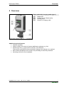
KeContact P20-U is a "charging station" for the indoor and outdoor area at which electrically
operated vehicles can be charged (e.g. electric automobiles).
The charging station is designed for installation on a wall or in a floor-mounted column.
The respective national regulations must be observed with regard to the installation and connection of the charging station.
The intended use of the device always includes the compliance with the environmental conditions for which this device was developed.
The device was developed, manufactured, inspected and documented in compliance with the
relevant safety standards. Therefore, the products do not pose any danger to the health of
persons or a risk of damage to other property or equipment under normal circumstances,
provided that the instructions and safety precautions relating to the intended use are properly
observed.
The instructions contained in this manual must be followed precisely in all circumstances.
Failure to do so could result in the creation of potential sources of danger or the disabling of
safety devices. Apart from the safety instructions given in this manual, the safety precautions
and accident prevention measures appropriate to the situation in question must also be observed.
Only electrical vehicles or their chargers may be connected. A connection of other loads (e.g.
electric tools) is not permitted!
1.3 About this manual
This manual is valid for devices of the type
KeContact P20-U
Use of this manual
This installation manual is intended for qualified personnel only 1.
The figures and explanations contained in this manual refer to a typical device design. The
design of the device may deviate from it.
Please refer to the "KeContact P20-U User manual" for information and instructions about
operating the device.
1
Persons who, due to their special training, expertise, and experience, as well as knowledge of current standards,
are able to assess the work performed and the possible hazards.
Installation manual, Version: 1.00 / Article no.: 90665
© KEBA 2012
7
KeContact P20-U
Important information
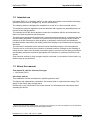
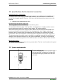
1.4 Product description
Example KC-P20-UC160130-000
Product family
-
Product type
Type / Version
-
KC
-
P
20
-
Type
KeContact
ChargePoint
Type plate
see top of the device
Design versions
0
1
Right
0
0
3
0
-
Optional
Customer code
4-digit
-
xxxx
Authentication
0
0…not populated
R…RFID
K…Key switch
Left
0…not populated
8
00…no cable
01…4m straight
99…4m spiraled
Options
Buttons
-
1…13A
2…16A
3…20A
4…32A
E…Europe (IEC61851)
J…Japan
U…UL (UL2594)
-
Electrics
0…Relays
6
Electronics
0...Basic
1...Basic+Multirating/Energy meter [MR/EM]
2...Basic+MR/EM+Ethernet Connection [ETH]
3...Basic+MR/EM+ETH+Powerline [BPL]
1
5…15A
6…30A
C
1…Type 1
U
Cable / Socket
C…Cable
Basic versions
Installation manual, Version: 1.00 / Article no.: 90665
© KEBA 2012
KeContact P20-U
Overview
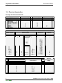
2 Overview
Base model with charging cable (type 1)
[A]…
[B]…
[C]…
[D]…
Status LED
Parking bay for charging plug
Housing cover
Hanger for charging cable
Charging station (application example)
Additional optional features
Network capability
Switch contact (for control of external additional equipment e.g. fan)
Enable input for e.g. ripple control receivers, time switches,…
This permits a scheduled (time-controlled) charging of the vehicle to be realized.
BPL modem (Broadband over Power Line) according to GreenPhy standard
Mounting column for floor installation
Installation manual, Version: 1.00 / Article no.: 90665
© KEBA 2012
9
KeContact P20-U
Installation guidelines
3 Installation guidelines
ATTENTION
Use only high quality shielded cables for the Ethernet connections "ETH" (see
also chapter “Ethernet1 connection “ETH”).
3.1 General criteria for the site selection
The charging station was constructed for the indoor and outdoor area. Accordingly, it is necessary to ensure the installation conditions and the protection of the device at the installation
site.
Take into account the local electrical installation regulations, fire prevention measures
and accident prevention regulations as well as emergency routes at this site.
The charging station must not be installed in potentially explosive zones (EX environment).
Mount the charging station so that it is not located in the direct flow of passersby and so
that no one can trip over connected charging cables and so that the charging cables do
not cover or cross passing pedestrian and motorized traffic.
Do not install the charging station at locations where ammonia or ammonia gas is exposed (e.g. in or at stables).
The mounting surface must be sufficiently constructed in order to withstand the mechanical forces.
Do not mount the charging station at locations where falling objects (e.g. hung ladders or
automobile tires) could damage the device.
Position the bottom of the charging station at a comfortable height and at least 460 mm
(18 inches) above the ground. Ensure that the status LED on the front can clearly be
seen by anyone who will be operating the device.
The device may not be exposed to direct spray water (by e.g. neighboring manual carwash facility, high-pressure cleaner, garden hose).
If possible, the device should be mounted protected from direct rainfall, in order to avoid
e.g. icing, damage because of hail or similar.
If possible, the charging station should be mounted protected from direct sunlight, in order to avoid the reduction of the charging current or the interruption of the charging procedure due too high temperatures of the components inside the charging station.
For not weatherproof mounting (e.g. in a parking lot outside), the charging current setting
is changed to 16A, if the temperature is inadmissible exceeded. Subsequently, the charging process can also be switched off.
For information about environmental conditions, please refer to the "Technical Data"
chapter.
Observe the national electric code and regulations.
10
Installation manual, Version: 1.00 / Article no.: 90665
© KEBA 2012
KeContact P20-U
Installation guidelines
3.2 Specifications for the electrical connection
Power supply line / components:
The power supply line must be connected permanent to an existing house installation and
correspond to the nationally applicable legal conditions. A socket outlet is not allowed to
connect the charging station. However, in all cases the following safety measures must be
installed:
Branch circuit protection max. 40 A
Dimensioning of the power supply line:
The charging station is set to 10 amps in the delivery state.
If a connection with more than 10 A is possible, an adjustment to a higher nominal current
must be performed using DIP switches (see chapter “DIP switch settings”).
When dimensioning the power supply line also observe the increased environmental temperatures inside the connection panel of the charging station (see “Supply terminals temperature rating”)! Under certain circumstances, this can lead to an increase of the cable
cross-section and to the adaptation of the temperature resistance of the power supply line.
The dimensioning of the cable must be checked by a qualified electrician for each house installation since reduction factors due to the type of installation, line length, environmental
conditions and material properties of the cable can have an influence on the cable selection.
Mains disconnector:
The charging station does not have its own power switch. The line circuit breaker in the panel
serves as mains disconnector.
3.3 Space requirements
Space requirements
If several charging stations are installed adjacent to each other, a distance of at least 200
mm between charging stations must be complied with.
Space requirements – dimensions in millimeters
Installation manual, Version: 1.00 / Article no.: 90665
© KEBA 2012
11
KeContact P20-U
Installation
4 Installation
Scope of supply (standard)
Charging station
Cable hanger (for versions with charging cable)
Installation manual (for the specialist)
User manual (for the end customer)
Drilling template
1 piece
1 piece
1 piece
1 piece
1 piece
Installation requirements
Before beginning the installation, the installation guidelines must be observed.
Contact person on-site (for access to the mains disconnector in the electrical distribution
panel board).
The electrical connection (power supply line) must be prepared.
Tool list
The following tools are required for the installation:
12
Flathead screwdriver for supply terminals (blade width 5.5 mm)
Flathead screwdriver for SELV terminals (blade width 3.0 mm)
Phillips head screwdriver PH2
Mounting tools for cable glands M16 (width across flats 20mm) and M32 (width across
flats 36mm)
LSA+ insertion tool (optional)
Installation manual, Version: 1.00 / Article no.: 90665
© KEBA 2012
KeContact P20-U
Installation
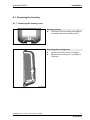
4.1 Preparing the housing
4.1.1 Removing the housing cover
Mounting screws
►
Unscrew the two mounting screws [S] on
the bottom side of the housing cover.
Mounting screws
Removing the housing cover
►
(1) Pull the housing cover out slightly.
►
(2) Slide the housing cover up slightly to
unhinge it.
Removing the housing cover
Installation manual, Version: 1.00 / Article no.: 90665
© KEBA 2012
13
KeContact P20-U
Installation
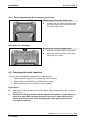
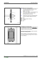
4.1.2 Removing/mounting the connector panel cover
Removing the connector panel cover
►
Unscrew the four screws that mount the
connector panel cover and remove the
connector panel cover.
Removing the connector panel cover
Information for reassembly
Mounting the connector panel cover
►
Insert the connector panel cover again.
►
Mount the connector panel cover again
using the four screws.
Connector panel cover removed
4.2 Preparing the cable insertion
There are three possibilities available for the cable insertion:
Cable insertion from above (conduit wiring; indoor/outdoor)
Cable insertion from behind (e.g. NM-B wiring; indoor)
Cable insertion with floor-mounted column (outdoor)
Preparations
►
Remove the connector panel cover (see Chapter "Removing/mounting the connector
panel cover").
►
14
Populate the charging station with the required cable glands, conduit fittings or
seals (if an open cable insertion opening is not used or cable insertion from
behind is performed). Use of the charging station with open cable insertion
openings is prohibited.
Installation manual, Version: 1.00 / Article no.: 90665
© KEBA 2012
KeContact P20-U
Installation
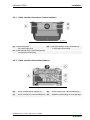
4.2.1 Cable insertion from above (indoor/outdoor)
Cable insertion openings - top view
[A]…Conduit fitting M32
(for power supply line)
[B]…Cable gland M16 (for control line/Ethernet)
or liquid tight conduit fitting
[C]…Cable gland M16 (for control line/Ethernet)
or liquid tight conduit fitting
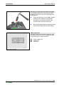
4.2.2 Cable insertion from behind (indoor)
Cable insertion openings - front view
[A]…
Knock out M32 (power supply line)
[B]…
Knock out M16 (for control line/Ethernet)
[C]…
Knock out M16 (for control line/Ethernet)
[D]…
M32/M16 conduit fittings to close openings
Installation manual, Version: 1.00 / Article no.: 90665
© KEBA 2012
15
KeContact P20-U
Installation
Breaking out the cable insertion openings
The marked positions for the required cable
feedthroughs on the rear of the housing must
be broken out.
►
Place the housing on on a stable support
pad and use a hammer and flathead
screwdriver to carefully break out the
required cable insertion openings.
►
All unused cable insertion openings at the
top must be sealed with conduit fittings.
Knock outs
Cable outlet box
A double flush-mounted cable outlet box with
separating divider for secure separation shall
be provided for the cable insertion.
[A]… power supply line
[B]… control line
[C]… Ethernet
Cable outlet box (example)
16
Installation manual, Version: 1.00 / Article no.: 90665
© KEBA 2012
KeContact P20-U
Installation
4.2.3 Cable insertion with floor-mounted column (outdoor)
Cable insertion openings - front view
[A]…Drill hole with conduit fitting
(for power supply line)
[B]…Feedthrough M16 with conduit fitting
(for control line/Ethernet)
[C]…Feedthrough M16 with conduit fitting
(for control line/Ethernet)
[D]…M32/M16 Liquid tight conduit fittings
Breaking out the cable insertion openings
The marked positions for the required cable
feedthroughs on the rear of the housing must
be broken out (only M16 knock outs).
►
Place the housing on on a stable support
pad and use a hammer and flathead
screwdriver to carefully break out the
required cable insertion openings.
Do not break out the marked M32 cable
insertion opening. If needed, a hole
must be drilled that fits to the used
cable conduit.
Breaking out the cable insertion openings
Installation manual, Version: 1.00 / Article no.: 90665
© KEBA 2012
17
KeContact P20-U
Installation
Drilling the cable insertion opening for the
power supply line
►
Drill a hole into the housing that fits to the
used cable conduit for the power supply
line. The position is beside the marked
M32 cable insertion opening.
The drill hole and the M32 knock out
must not touch each other.
Drilling the cable opening
Cable insertion openings
►
All cable insertion openings at the rear
side must be equipped with a cable
conduit [A] as shown on the picture.
►
All cable openings [D] at the top must be
closed with liquid tight conduit fittings.
Ground connection
In case of metal conduits, a ground connection
is required aswell as the floor-mounted column.
Charging station on floor-mounted column
18
Installation manual, Version: 1.00 / Article no.: 90665
© KEBA 2012
KeContact P20-U
Installation
4.3 Mounting the charging station
A proper mounting is absolutely necessary
and lies outside of the scope of responsibility of KEBA AG.
Marking the holes
►
Mark the four holes [1] to [4] using the
supplied drilling template and a spirit
level.
►
Marking the holes
Drill the four mounting holes.
Information about the drilling template:
The drilling template shows the outer contour of
the charging station.
The four main mounting holes are aligned centered to the slotted holes on the device.
The three holes in the upper right show the area
for the cable insertions and help to be able to
align the mounting position of the device to the
cables.
The two notches on the top side are used for
aligning the device to the connection lines.
In the lower part, the holes for the optional cable
hanger can be drilled appropriate to the device.
This part can be separated if the cable hanger is
not mounted or is to be mounted at a different
location.
Water drainage
The water drainage from the top side to the rear
side of the charging station must be ensured.
Therefore, observe the following:
Only a vertical installation of the charging
station is permitted.
The charging station must be mounted at an
angle of 90° (no inclination is permitted!).
Water drainage
Installation manual, Version: 1.00 / Article no.: 90665
© KEBA 2012
19
KeContact P20-U
Installation
Mounting the charging station
►
Turn the hanger bolts into the anchors
until the thread still protrudes
approx. 2 cm ('x').
►
Use the shims [A] to compensate for any
unevenness and to ensure a water
drainage behind the device.
►
Position and mount the charging station
using the supplied washers and nuts.
[A]…shim
[B]…charging station housing
[C]…washer
[D]…nut
Schematic diagram
Installation on hollow walls
For installation on hollow walls, at least two
mounting screws must be secured to a support
element of the wall (see figure).
Special hollow-wall anchors must be used for
the other mounting screws.
When installing on hollow walls you must ensure that the bearing strength of the construction is sufficient.
Installation on hollow walls
20
Installation manual, Version: 1.00 / Article no.: 90665
© KEBA 2012
KeContact P20-U
Installation
4.4 Electrical connection
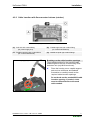
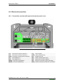
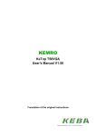
4.4.1 Connection overview with opened connector panel cover
Connection overview
[L1]… Connector for Phase conductor 1
[L2]… Connector for Phase conductor 2
[Gnd]…Connector for earth ground conductor
[F1]… Fuse holder for L1
[F2]… Fuse holder for L2
[DSW1]…DIP switch configuration
[DSW2]…DIP switch addressing
Installation manual, Version: 1.00 / Article no.: 90665
© KEBA 2012
[T1]… Service button
[LED]…Status LED (internal)
[X1]… Enable input "IN"
[X2]… Switch contact output "OUT"
[X3]… Ethernet2 connection (debug)
[X4]… Ethernet1 connection (LSA+ terminals)
[Shd]…Shield connection for Ethernet1 connection
21
KeContact P20-U
Installation
4.4.2 Connecting the power supply line
Running the power supply line
(conduit wiring)
►
Run the power supply line from ABOVE
as shown in the figure.
[A]…Conduit
[B]…Cable gland
Running the power supply line
Running the power supply line
(e.g. NM-B wiring)
►
Run the power supply line from BEHIND
as shown in the figure.
Running the power supply line
22
Installation manual, Version: 1.00 / Article no.: 90665
© KEBA 2012
KeContact P20-U
Installation
Connecting the power supply line
►
Shorten the connection wires to the
appropriate length; these should be kept
as short as possible.
The ground conductor must be longer
than the remaining conductors!
►
Strip approx.12 mm from the connection
wires.
Wire end sleeves are recommended for
finely stranded wires.
►
Perform the connection of the power
supply line [L1], [L2] and [Gnd].
Observe which phase conductor you
connect to terminal [L1] if several
charging stations are installed in a
network (DIP switch settings for load
management).
Connecting the power supply line (example)
Supply terminals
The supply terminals are designed as springtype terminals.
Terminal data:
- inflexible (min.-max): 0.2 – 16 mm²
- flexible (min.-max):
0.2 – 16 mm²
- AWG (min.-max):
24 – 6
- flexible (min.-max) with wire end sleeve:
Without/with plastic sleeve
0.25 – 10 / 0.25 – 10 mm²
- Stripping length:
12 mm
- Flathead screwdriver: 5.5 mm
Supply terminals
Installation manual, Version: 1.00 / Article no.: 90665
© KEBA 2012
23
KeContact P20-U
Installation
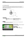
4.4.3 Enable input "IN"
The enable input equipped for use with a potential-free contact. Using the enable input, it is
possible to control the charging station using external components (e.g. external key
switches, ripple control receiver of the energy supplier, house control, time switches, combination lock, photovoltaic system etc.).
Circuit diagram:
Logical function:
Enable contact
open
closed
State of the charging station
LOCKED
READY FOR OPERATION
Connection:
►
Connect the wires to the enable input "IN" (please refer to the "Terminals [X1/X2]"
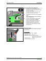
chapter for details about the terminal).
DIP switch setting
The use of the enable input must be activated
by a DIP switch setting.
Use enable input:
- "Yes":
DSW1.1 = ON
- "No":
DSW1.1 = OFF (Default)
DIP switch setting
24
Installation manual, Version: 1.00 / Article no.: 90665
© KEBA 2012
KeContact P20-U
Installation
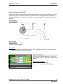
4.4.4 Switch contact "OUT"
The switch contact is a potential-free relay contact and can be used for activating a fan in the
garage. This can be necessary with some vehicles. Please consider building requirements
and car requirements. If a fan has to be used, the corresponding DIP switch settings must be
selected.
Circuit diagram:
Electrical data:
- Class 2 circuit Vcc < 30VAC
- Fuse F = 0.5A slow-blow
Connection:
►
Connect the wires to the switch contact "OUT" (please refer to the "Terminals [X1/X2]"
chapter for details about the terminal).
DIP switch setting
The use of the switch contact (e.g. for the fan
specification) must be activated by a DIP switch
setting.
Use the switch output:
- "Yes":
DSW1.2 = ON
- "No":
DSW1.2 = OFF (Default)
DIP switch setting
Installation manual, Version: 1.00 / Article no.: 90665
© KEBA 2012
25
KeContact P20-U
Installation
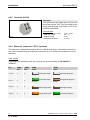
4.4.5 Terminals (X1/X2)
Terminals
The terminals for the enable input "IN" [X1] and
the switch contact "OUT" [X2] are designed as
spring-type terminals. Only Class 2 circuit connections are allowed.
Terminal data:
- Cross-section (min.-max):
- AWG (min.-max):
- Stripping length:
- Flathead screwdriver:
terminal
0.08 – 4 mm²
28 – 12
8 mm
3,0 mm
4.4.6 Ethernet1 connection "ETH" (optional)
The Ethernet1 is designed as terminal block in LSA+® technology. A hardwired communication can be realized using the Ethernet1 connection (e.g. for smart home integration or fleet
solutions).
Color coding:
According to the standards used, the contacts are wired according to TIA-568A/B for
100BaseT:
Pin
-568A
Pair
-568B
Pair
1 (Tx+)
3
2
2 (Tx−)
3
2
3 (Rx+)
2
3
4 (Rx−)
2
3
26
-568A
Color
-568B
Color
white/green stripe
white/orange stripe
green/white stripe
orange/white stripe or
orange
or green
white/orange stripe
white/green stripe
orange/white stripe
or orange
green/white stripe or
green
Installation manual, Version: 1.00 / Article no.: 90665
© KEBA 2012
KeContact P20-U
Installation
Terminal data:
Category
Inflexible cable
Cat 5e / Cat6 STP
Cat 6 STP
Wire diameter
0.36 mm (AWG 27)
Insulation diameter
0.7 – 0.75 mm
0.4 – 0,64 mm
(AWG 26 – AWG 22)
0.7 – 1,4 mm
0.51 – 0,81 mm
(AWG 24 – AWG 20)
1.0 – 1,4 mm
7 x 0.2 mm
(AWG 24)
1.1 – 1,4 mm
Flexible cable
Cat 5e / Cat 6 STP
LSA+® insertion tool
Original KRONE insertion tool with solder-free
and stripping-free connection of the wires and
simultaneous trimming of the residual lengths.
LSA+® insertion tool
Preparing the connection cable
►
Strip the connection cable approximately
6 cm.
►
Fold back approx. 1 cm of shielded
braiding completely and wrap it with
conductive adhesive textile tape.
Preparing the connection cable
Connecting the cable
►
Secure the connection cable at the point
of the wrapped shielded braiding in the
cable clamp [K].
The cable clamp must be screwed onto
the shield point [Shd] of the circuit board.
►
Clamp the wires to the terminal block
[ETH] using the insertion tool.
Connecting the cable
Installation manual, Version: 1.00 / Article no.: 90665
© KEBA 2012
27
KeContact P20-U
Installation
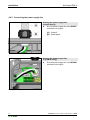
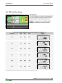
4.5 DIP switch settings
DIP switches
The DIP switches are used for the addressing
and configuring the charging station and are
located under the connector panel cover.
[DSW1]…configuration (upper DIP switch)
[DSW2]…addressing (lower DIP switch)
DIP switches
SETTING THE MAXIMUM EVSE CURRENT CAPACITY (DSW1) (*1)
D1.6
D1.7
D1.8
Current
Figure
10A
OFF
OFF
OFF
13A
ON
OFF
OFF
16A
OFF
ON
OFF
20A
ON
ON
OFF
25A
OFF
OFF
ON
30A
ON
OFF
ON
(*1) Preadjusted maximum current value for the EV charger (control pilot duty cycle).
28
Installation manual, Version: 1.00 / Article no.: 90665
© KEBA 2012
KeContact P20-U
Function
Installation
INPUT/OUTPUT (DSW1) / ONLY FOR STANDARD MODE
DIP switch
Figure
External enable input "IN" is
used
D1.1
ON=yes
Switch output "OUT"
is used
(fan specification)
D1.2
ON=yes
STANDARD MODE (DSW2)
Standard-setting: (DSW2.1 to 2.4=OFF):
The charging procedure in STANDARD mode is
carried out automatically by the charging station
without higher-ranking control system.
The charging station attempts to obtain an IP
address via DHCP server, if needed.
This also corresponds to the basic settings for
charging stations with out network connection.
Static IP address (DSW2.6=ON):
The charging station has the static IP address:
[192.168.25.11]
LOAD MANAGEMENT MODE / ADDRESSING (DSW2)
The charging procedure in LOAD
MANAGEMENT mode is controlled by a higherranking load management system.
Since multiple charging stations are located in a
network; an addressing of the charging stations
is necessary.
The addressing is done via the DIP switches
DSW2.1 to DSW2.4.
The 4-bit addressing results in 15 possible
Ethernet addresses [192.168.25.xx].
DSW2.1 = Address Bit 20 (Value=1)
DSW2.2 = Address Bit 21 (Value=2)
DSW2.3 = Address Bit 22 (Value=4)
DSW2.4 = Address Bit 23 (Value=8)
Example for address "17":
DSW2.1 = ON (Value=1)
DSW2.2 = ON (Value=2)
DSW2.3 = ON (Value=4)
DSW2.4 = OFF (Value=0)
Address= 10 + 1 + 2 + 4 + 0 = 17
The settable Ethernet addresses start at 10 +
DIP switch setting.
Installation manual, Version: 1.00 / Article no.: 90665
© KEBA 2012
29
KeContact P20-U
Installation
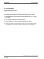
4.6 Commissioning
General commissioning process
1. Remove all residual installation and connection materials from the connector panel area.
2. Before commissioning, check all screw and terminal connections for firm seating!
3. Check whether all unused cable glands are properly sealed with blind plugs or dummy
screw fittings.
4. Close the connector panel cover to the charging station.
5. Mount the housing cover (see the " Mounting the housing cover" chapter).
6. Switch on the voltage of the power supply line. After 15 to 20 seconds, the status LED
must flash green slowly. The device performs a self test every time it is switched on.
30
Installation manual, Version: 1.00 / Article no.: 90665
© KEBA 2012
KeContact P20-U
Installation
4.6.1 Mounting the housing cover
Fitting the housing cover
►
Fit the housing cover at the top and push
the cover downwards slightly.
Make sure that the housing cover is
seated correctly at the top in the housing
guides.
Fitting the housing cover
Mounting the housing cover
►
Then fold the housing cover to the rear.
The housing cover must glide into the
guides without considerable resistance.
►
Make sure that the housing cover is
seated correctly on all sides in the
housing guide.
Only a minimum, even gap may be
present.
Mounting the housing cover
Mounting screws
►
Secure the housing cover at the bottom
using the two mounting screws [S].
Mounting screws
Installation manual, Version: 1.00 / Article no.: 90665
© KEBA 2012
31
KeContact P20-U
Technical instructions
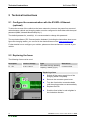
5 Technical instructions
5.1 Configure the communication with the EV BPL->Ethernet
(optional)
To allow the access of the vehicle to the home network or internet, the power line communication between vehicle and charging station must be configured on both sides with the equal
password (NMK „Network Membership Key“).
The default password is „emobility“. It is recommended to change this password.
The required software ("EV Communication Assistant“) including the instructions how to configure the charging station, you can find in the download area under www.kecontact.com.
Further details how to configure your vehicle, please see the manufacturer’s manual of your
vehicle.
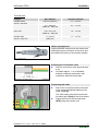
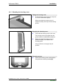
5.2 Replacing the fuses
The following fuse must be used:
Description
Current / Voltage
F1 + F2
3.15 A / 250 V
Type
Slow-blow with high breaking
capacity (>1500A) (T) (H)
Dimensions
5 x 20 mm fuse
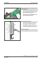
Replacing a fuse
►
Switch off the power supply line of the
charging station completely.
►
Remove the connector panel cover.
►
Turn the fuse holder counterclockwise
until the spring pushes out automatically.
►
Replace the fuse.
►
Push the fuse holder in and retighten in
the clockwise direction.
Opening a fuse holder
32
Installation manual, Version: 1.00 / Article no.: 90665
© KEBA 2012
KeContact P20-U
Technical instructions
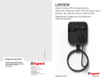
5.3 Dimensions
Dimensions in millimeters
Installation manual, Version: 1.00 / Article no.: 90665
© KEBA 2012
33
KeContact P20-U
Technical instructions
5.4 Technical data
Electrical data
Cable feed:
Conduit wiring or NM-B wiring
Mains connection cross-section:
Minimum cross-section
- 3 x AWG 10
Mains supply terminals:
Connection line:
- AWG (min.-max):
24 – 6
Supply terminals temperature rating:
105°C
Potential-free switch output OUT:
Class 2 circuit voltage <30VAC 50/60Hz
External fuse 0.5AT required
Connection line:
- AWG (min.-max):
28 – 12
Nominal current
(configurable connection values):
10A, 13A, 16A, 20A, 25A or 30A
Single phase 3 wire
Mains voltage:
120/240V
120/208V Y
Line frequency:
60Hz
Overvoltage category:
III according to UL 840
Branch circuit protection:
Max. 40A
CCID 20:
IΔN=20mA according to UL 2231
Cable version:
Type 1 cable: 30A / 240 VAC
according to SAE-J1772
Type of equipment:
AC Level 2
permanent connection
Type rating (UL 50):
IP protection rating for device (IEC 60529):
Type 3R
IP54
Mechanical data
Dimensions (W x H x D):
240 x 643 x 140 mm (without charging plug)
Weight:
approx. 6.5 kg
34
Installation manual, Version: 1.00 / Article no.: 90665
© KEBA 2012
KeContact P20-U
Technical instructions
Environmental conditions
Operating temperature at 30A:
-30C to +50C
without direct sunlight
Temperature behavior:
In each case of the specified operating temperature
range, the device supplies the charging current
continuously available.
To increase the charging availability, the charging
current setting is changed to 16A, if the temperature is inadmissible exceeded. Subsequently, the
charging process can also be switched off.
After cooling, the charging current setting is increased again.
This is not a safety feature, this is only an operational feature. Environmental operating temperature
has to be obtained.
Storage temperature range:
-25C to +80C
Speed of temperature change:
max. 0.5C /min
Permitted relative air humidity:
5% to 95% non-condensing
Altitude:
max. 2000 m above sea level
5.5 Standards and regulations
National regulations (USA)
FCC Title 47, Part 15
Digital Device Class B
NEC Article 625
Electric vehicle charging systems
National regulations (Canada)
CSA C22.2 No. 107.1 General Use Power Supplies
ICES-003
Class B
Approved standards
UL 2594
Electric vehicle supply equipment
UL 2231-1
Personnel protection systems for electric vehicle (EV)
Supply circuits: General requirements
UL 2231-2
Personnel protection systems for electric vehicle (EV)
Supply circuits: Particular requirements for protection devices for use in charging systems
UL 991
Tests for Safety-related controls employing solid-state devices
UL 1998
UL 61010
Software in programmable components
Electrical Equipment For Measurement, Control, and Laboratory Use; Part 1:
General Requirements
Installation manual, Version: 1.00 / Article no.: 90665
© KEBA 2012
35