1
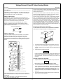
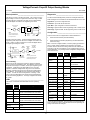
This Datasheet for the
IC660BBA100
Block 115Vac Analog 4 Inputs / 2 Outputs
http://www.cimtecautomation.com/parts/p-14422-ic660bba100.aspx
Provides the wiring diagrams and installation guidelines for this GE Series 90-30
module.
For further information, please contact Cimtec Technical Support at
1-866-599-6507
[email protected]
Voltage/Current 4 Input/2 Output Analog Blocks
June 2002
GFK-0048E
Description _____________________________________
Specifications __________________________________
Catalog Numbers
Voltage/Current 4 Input/2 Output Analog Blocks have four
independent input circuits and two independent output circuits. Two
block versions are available:
115 VAC Voltage/Current Analog I/O Block (IC66*BBA100)
24/48 VDC Voltage/Current Analog I/O Block
(IC66*BBA020)
115 VAC Analog I/O Block
Terminal Assembly
IC66*TSA100
Electronics Assembly
IC66*EBA100
24/48 VDC Analog I/O Block
These blocks are identical except for the power supply.
IC66*BBA100
IC66*BBA020
Terminal Assembly
IC66*TSA020
Electronics Assembly
IC66*EBA020
Block Specifications
Analog In/Out
(115V 50/60Hz)
(.1A Max)
Size (height x width x depth)
8.83” (22.44cm) x 3.34” (8.48cm)
x 3.91” (9.93cm)
Weight
4 lbs. (1.8 kg)
LEDs (I/O Block)
Unit OK, I/O Enabled
Block to Block Isolation
1500 V
Heat Dissipation
6 Watts
Block Power (nominal);
115 VAC
24/48 VDC
98-132 VAC
10VA
47-63Hz
1 cycle
18-56
8W
10% max. ripple
10ms
Operating range
Maximum power
Frequency/ripple
Power supply dropout time
50mS Pt/Max
Features ______________________________________
Common mode rejection
Common mode voltage
60 dB (0-1 KHz)
+/-170 volts, maximum
Absolute accuracy (at 25°C):
Typical: +/-0.2% of full scale;
Maximum: +/-0.5% of full scale:
Each circuit on an 4 Input/2 Output Analog Block can accept or
provide signals in one of five analog ranges:
Within:
0-10 volts DC
-10 volts DC to +10 volts DC
Thermal drift (from 25°C):
Typical: 10 PPM per °C;
Maximum: 40 PPM per °C
Circuit range selections
0-10 VDC, +/-10 VDC, +/-5 VDC, 0-5 VDC,
4-20 mA (or 1-5 VDC)
-5 volts DC to +5 volts DC
0-5 volts DC
4-20 mA/1-5 volts DC
External scaling resistor:
to set full scale to 5 volts
for 10mA to 50mA loops
This flexibility allows these blocks to be used with a wide variety of
analog input and output devices. The block’s internal power supply
drives current mode output loads up to 300 Ohms each. For loads
up to 2K Ohms, an external 24 or 48 VDC power supply can be
used.
1/2 Watts or greater
100W / 1 Watt
Input Specifications
Input resolution
Input update frequency
Input filter ranges
Input diagnostics
Configurable block features include:
50mV on the 10 volt range,
25mV on the 5 volt range,
100mA on the 4 to 20 mA range.
Independent scaling for each input and output.
Fault reports to the host can be enabled or disabled for each
input and output.
Selectable Input Filter Time up to 1024ms.
Each input can operate in normal analog input mode, or report
only its alarm status.
Low and high alarm limits for each input, in either normal input
mode or alarm input mode.
Powerup default values for each output.
Each output can be configured to hold last state or default if
CPU communications are lost.
Input Low Alarm and High Alarm detection.
Open Wire detection on current mode inputs.
Input Underrange or Overrange.
12 bit + sign
Once every 4ms
Underrange, Overrange.
Voltage mode: 2000 Ohms or greater;
Current mode: 0 to 300 Ohms
Output Specifications
Output resolution
Output update frequency
Output diagnostics
Output load
12 bit + sign
Once every 4ms
Underrange, Overrange.
Voltage mode: 2000 or greater;
Current mode: 0 to 300 Ohms
Refer to GFK-0867 for product standards and general specifications.
* In the presence of severe RF interference (IEC 801-3, 10 V/m),
accuracy may be degraded to +/- (0.5% of full scale reading plus 0.5%
of reading).
Output Underrange or Overrange.
1
Voltage/Current 4 Input/2 Output Analog Blocks
June 2002
GFK-0048E
Compatibility _________________________________
Grounding
These blocks are backward-compatible with earlier versions, and
may be used to replace them.
The block’s mounting screws must not be used as the only means of
grounding the block. Connect the green ground screw on the block to a
reliable ground system using a short wire lead, minimum size AWG #12
(avg 3.3mm2 in cross-section).
Any Hand-held Monitor (IC66*HHM500 or HHM501) can be used
with these blocks. However, Hand-held Monitor model
IC66*HHM501 is required to change baud rate configuration, or to
configure redundancy features. Note that older HHM model
IC66*HHM501 version 3.5 may incorrectly display the message
WIRING ERROR during normal operation. Upgrading the HHM to a
later version corrects this problem.
Warning
If mounting screws do not make good ground connection and the
ground screw is not connected to a reliable ground, the block is not
grounded. Electrical shock hazard exists. Death or personal injury
may result.
For an IC697 series PLC, the CPU and programming software must
be version 2.0 or later. The bus controller must be IC697BEM731C
or later.
Block Wiring _________________________________
Do not overtorque the terminal screws. Recommended torque for all
terminals is 6 in/lb (.678 N/M).
For an IC600 series PLC, the CPU must be rev. 105 or later. For an
IC600 series “Plus” PLC rev. 110 or later is required. The
programming software must be rel. 4.02 or later.
Serial Bus Wiring
For an IC550 series PLC, the CPU must be rev. 3.0 or later. The
programming software must be rel. 2.01 or later.
Terminals 1 to 4 are for the serial bus. These terminals accept one
AWG #12 wire (avg 3.3mm2 cross-section) or two AWG #14 wires
(each avg 2.1mm2 in cross-section). The minimum recommended wire
size is AWG #22 (avg .36mm2 in cross-section).
Current-source analog blocks are preferred for current-loop
applications. Please request information about:
115VAC/125VDC Current-source Analog 4 Input/2 Output Block
(IC66*BBA104)
24/48 VDC Current-source Analog 4 Input/2 Output Block (IC66*BBA024)
115VAC/125VDC Current-source Analog Output Block (IC66*BBA105)
115VAC/125VDC Current-source Analog Input Block (IC66*BBA106)
24/48 VDC Current-source Analog Block Input Block (IC66*BBA026)
Terminals 1 - 4 can also accommodate spade or ring terminals up to
0.27 inch (6.85mm) wide with a minimum opening for a #6 screw, and up
to 0.20 inch (5.1mm) depth from the screw center to the back barrier.
Be sure unshielded wire ends are not longer than 2 inches (5 cm).
Using one of the cable types recommended in the System and
Communications User’s Manual, connect the serial bus to terminals 1- 4.
Using this Datasheet ____________________________
This datasheet summarizes information about block installation,
configuration, and diagnostics.
1
SERIAL 1
2
SERIAL 2
Your primary reference should be the Discrete and Analog Blocks
User’s Manual. It includes detailed instructions for block installation
and configuration.
3
SHIELD IN
4
SHIELD OUT
For additional information about systems and communications,
including bus specifications, refer to the I/O System and
Communications Manual.
If the block is at either end of the bus, connect a terminating resistor of
the appropriate type (see the System and Communications User’s
Manual for details) across its Serial 1 and Serial 2 terminals.
Installation Instructions _________________________
Start
of Bus
Carefully inspect all shipping containers for damage. If any
equipment is damaged, notify the delivery service immediately. Save
the damaged shipping container for inspection by the delivery
service. After unpacking the equipment, record all serial numbers.
Save the shipping containers and packing material in case it is
necessary to transport or ship any part of the system.
Terminating
Resistor
Serial 1
Serial 2
Shield In
Shield Out
Block Mounting
Genius I/O blocks are considered "open equipment" and therefore
must be installed within a protective enclosure. They should be
located in an area that is clean and free of airborne contaminants.
There should be adequate cooling airflow.
The block can be mounted right side up, or upside down. Leave at
least 2 inches of space between blocks. Mount the block by drilling
two screw or bolt holes for 8-32 hardware. Position the block so that
the notches in the upper and lower flanges line up with the mounting
holes. Mount the block using 8-32 screws. Use star washers to
provide ground integrity.
2
End
of Bus
Terminating
Resistor
Serial 1
Serial 2
Shield In
Shield Out
Voltage/Current 4 Input/2 Output Analog Blocks
June 2002
GFK-0048E
If current mode (4-20mA) is used for an input without an external
resistor, connect a jumper from the terminal marked JMP to the terminal
marked RTN for that circuit.
Field Wiring ___________________________________
Terminals 5 to 32 are for field devices. They take a single wire up to
AWG #14 (avg 2.1mm2 in cross-section). Minimum recommended
size is AWG #20 (avg .54mm2 in cross-section).
If an input current device operates outside the 4-20mA range, connect a
resistor across the voltage inputs. For example, to measure 10mA to
50mA current loop signals, install a 100 ohm resistor.
Wiring for Block Power
If current mode is used for an output circuit, use the terminals marked I+
and I-. For outputs set up in current mode, the block’s internal power
supply can be used to drive loads up to 300 Ohms per output. For loads
up to 2K Ohms, use an external power supply. Connect the positive
lead of the external supply to one side of the load, and the negative lead
of the external supply to block common on terminal 29. If the external
supply is between 24V and 50V, you can use terminal 25 or 30 as a tie
point for the positive connection. This point will be disconnected from the
external supply by a reverse biased diode.
For block power, connect the power source to terminals 6 and 7.
For a 24/48 VDC block, connect the source to the DC+ terminal and
the return to the DC- terminal. For a 115 VAC block, connect the
source to the H terminal and neutral to the N terminal.
For the 115 VAC block version (IC66*BBA100) only, if Class 1
Division 2 conditions must be met for Factory Mutual, install an
external 250 volt 1/8 amp slow-blow fuse in series with the Hot AC
power connector as shown below.
Removing an Electronics Assembly _______________
250V, 1/8 Amp Slow-Blow Fuse
H
The block’s Electronics Assembly can be replaced with a compatible
model without removing field wiring or reconfiguring the block.
6
~
N
Electronics
Assembly
7
Retaining
Screws
(Qty. 2)
Wiring for I/O Devices
The ground (GND) terminal (5) is for block safety. It is connected
internally to the block chassis, and to terminals 12, 20, and 28,
which are marked GND. Each pair of signals has one ground
terminal and one common terminal, for shield termination if desired.
The three common terminals are connected together internally to the
source.
BA100
Terminal
Assembly
Connector
Pins
BA020
6
6
7
7
~
NEUT
Power for each model
1
Serial 1
2
Serial 2
3
Shield In
4
5
6
Power
7
8
9
10
V
11
12
13
14
i
*
15
16
17
18
V
19
20
21
22
i
**
23
24
25
26
Load
2000 Ohms max.
27
28
29
30
Load
0-300 Ohms
31
32
Shield Out
GND
DC+
DC NC
IN
JMP
RTN
GND
COM
IN
JMP
RTN
IN
JMP
RTN
GND
COM
IN
JMP
RTN
I+
IVOUT
GND
COM
I+
IVOUT
1.
Unscrew the retaining screws at the top and bottom of the block.
2.
Using a Block Puller (IC660BLM507), engage the tabs in the first
vent slots. Move the tool to the center of the block and squeeze the
handle.
3.
Pull the Electronics Assembly upward.
Warning
If power is applied to the field terminals, power is also exposed on the
connector pins at the base of the Terminal Assembly, and electrical
shock hazard exists. Do not touch the connector pins! Death or injury
may result.
Input 1
Input 2
Inserting an Electronics Assembly
Input 3
1.
Align the Electronics Assembly in the guides and push down firmly.
Caution
Input 4
Do not exert excessive force; it may damage the block.
Output 1
2.
If unusual resistance is met, remove the Electronics Assembly. If
power is applied to the block, DO NOT TOUCH THE CONNECTOR
PINS! Inspect the Terminal Assembly, connector receptacle, and
connector edge board (on the Electronics Assembly). Be sure the
keying matches. Remove any obstacles and reinsert the
Electronics Assembly. Pay close attention to the alignment of the
guide pins.
3.
Secure the Electronics Assembly with the screws on the top and
bottom of the Terminal Assembly.
Output 2
* External Connection
** External 100 Ohm, 1 W Precision Resistor for 10mA to 50mA range.
For a voltage input device, connect the device in series between V+
and the terminal marked IN for that input. Connect V- to the terminal
marked RTN.
For a voltage output device, connect the load to the terminals
marked VOUT and COM for that output.
3
Voltage/Current 4 Input/2 Output Analog Blocks
June 2002
GFK-0048E
Block Operation ________________________________
Diagnostics _________________________________
The first four circuits on the block are inputs. They convert incoming
signal voltage or current to a digital count value in the range +/-4095.
If scaling has been configured for an input, the block automatically
scales the digital count value to an engineering units value.
The block’s advanced diagnostics provide the messages listed below.
Fault messages can be cleared from the Hand-held Monitor or the CPU.
A/D
Low Alarm: Input under its low alarm limit
Open Wire: Input configured for 4-20mA is below 2mA
Analog to Digital
Converter
Processor
High Alarm: Input over its high alarm limit
IN
Shield
AMP
MUX
Overrange: Signal exceeds +32767 engineering units or +4095 counts
JMP
Filter
Underrange: Signal exceeds -32767 engineering units or -4095 counts
RTN
Configuration ___________________________________
COM
NOTE:
Common ground and case
ground are shared between
Power
Supply
Ground
two output channels
GND
Case
First, the block must be configured with a Hand-held Monitor to:
Ground
Circuits 5 and 6 are outputs. The block will automatically scale an
engineering units output from the CPU to a digital count value in the
range +/-4095. The D/A converter then converts the digital value to
an output signal voltage or current.
+20V
+1
-1
VOUT
COM
GND
Buffer
Amplifier
V to I
Converter
Sample
Hold
Circuitry
S/H
Enter its Device Number (serial bus address).
Enter its Reference Number (required only for IC600 and IC550
series PLCs only).
Note: If a block is configured offline, it must be properly grounded and
have a 75 Ohm resistor installed across its Serial 1 and Serial 2
terminals. See the Discrete and Analog I/O Blocks User’s Manual for
instructions. The rest of the features can be configured either using a
Hand-held Monitor, or by sending a Write Configuration datagram to the
block from the host.
12 bits plus
sign D/A
Converter
D/A
Processor
Feature
NOTE:
Power
Supply
Ground
Common ground and case
Circuit
or Block
Factory
Setting
Selections
Device Number
Block
null
0 to 31 (a number must
be selected)
Reference
Address
Block
none
Depends on host CPU
type
Each circuit can be configured for scaling to represent a different
type or increment of engineering units. The default for each circuit is
to operate in the range of +/-10VDC, and to report engineering units
of millivolts. If millivolts are not appropriate or if the circuit will
operate in a different voltage/current range, the circuit should be
rescaled. Instructions are given in the Discrete and Analog Blocks
User’s Manual. The possible range of engineering units values is
+/-32767. A circuit can also be configured for no scaling; in that
case, it uses unscaled digital count values that correspond directly
to the actual analog signal level. The range of digital counts values
is +/-4095.
Baud Rate
Block
153.6 std
Report Faults
Circuit
yes
153.6 std, 153.6 ext,
76.8, 38.4 Kbd
yes/no
Range Select*
Circuit
+/-10VDC
0-10VDC, +/-10VDC, 05VDC, 5VDC, 4-20mA (15VDC)
Scaling Points
Circuit
+/-10000,
+/-4095
+/-32767, +/-4095
Input Filter Time* Circuit
128ms
none, 8-1024ms
LEDs _________________________________________
Alarm Input Mode Circuit
no
yes/no
The block's Unit OK and I/O Enabled LEDs show its operating
status:
Alarm Thresholds Circuit
+/-10000
+/-32767
Hold Last State
Circuit
no
yes/no
Output Default
Circuit
0
+/-32767 eng. units
BSM Present
Block
no
yes/no
Block
3 bus scans 2.5/10 seconds
Case
Ground
ground terminals are shared
between output channels
Circuit Scaling
Unit OK
I/O
Enabled
Meaning
ON
ON
Block functioning, CPU communicating
ON
OFF
Block functioning
No CPU communications for 3 bus scans
Outputs Default
Time
ON
Blinking
Block functioning, Circuit forced
CPU Redundancy Block
none
none/standby
Blinking
ON
Circuit fault, CPU communicating
disabled
enabled, disabled
Blinking
OFF
Configuration
Protection
Circuit fault
No CPU communications for 3 bus scans
Alternate Blinking
Circuit fault, Circuit forced
Synchronous
Blinking
No CPU communications - block number
conflict
OFF
No block power, or block faulty
OFF
Block
* These are setup parameters. They must NOT be changed while the
block is operating. If either is changed while the block is operating, the
voltage of the circuit also changes.
4