1
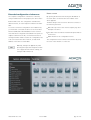
Manual TouchEntry®
Attractive all-in-one solution
Stand-alone solution without PC and without separate controller
About this manual
Thank you for choosing a quality product from the
company Adatis.
This product is manufactured with modern
manufacturing techniques and extensive quality
assurance measures. We are trying to do everything
to make you happy with this device and that you can
easily work with it.
If you have questions about your device, please contact
your sales representative or contact us directly.
Adatis is constantly working on the development of all
devices and versions, Therefore we reserve changes in
the scope of delivery form, technology and equipment.
From any text and illustrations of this manual no claims
can be derived.
Adatis GmbH & Co. KG
version 2.004
page 2 of 25
Table of contents
About this product
4
Features
Equipment overview
Content of delivery
4
5
5
Start of operation
6
Special RFID cards
6
Configuration via LCD menu
24
25
7
IP address
Camera
Audio
Display
7
8
10
11
Installing visitor communication
11
LCD display settings
Installing destinations
Installing phone book
11
11
11
Using visitor communication
11
Ring button
Dialing from the phone book
Control during the connection
11
13
14
Installing access control
14
Input of employee data
Enrollment
RFID Enrollment
14
14
14
Using access control
15
Access via RFID
Access via PIN code
15
16
Video surveillance
Extended configuration via browser
17
18
Home screen
Set password
Language selection
System information
Menu configuration
Basic settings
Access control
Network settings
SIP configuration
RFID configuration
Card management
Special cards
Audio/Video
Interface configuration
Upload Firmware
Upload Firmware
18
19
19
19
19
19
19
19
19
19
19
19
20
20
20
20
Interfaces
21
Pin assignment of the block
Relay output
Gate inputs
Serial interface
External power supply
21
21
22
22
23
Adatis GmbH & Co. KG
Glossary
Declaration of Conformity
version 2.004
page 3 of 25
Features
About this product
TouchEntry is a new access control terminal, which
elegantly combines access control and visitor communication. TouchEntry is thus a representative business card at the front door of your company.
The TouchEntry access control solution offers the
access option of a RFID card and / or a PIN code.
RFID and PIN-code: Additionally or alternatively the
access is possible via encrypted RFID cards or tags,
or via PIN code.
Audiovisual communication: The visitor communication works through hands-free talking. Meanwhile
the built-in camera records with 100 degree wideangle lens the situation at the door.
At the same time TouchEntry also allows audiovisual
communication: Visitors can connect to the reception
desk or a contact person. The operation is performed
intuitively with a touch screen.
The data connection is via Ethernet and is compatible
with modern voice-over-IP SIP standard. Integrated
interfaces support connections of external components.
Intuitive touch screen operation: The familiar control of smart phones with a touch screen allows intuitive operation and flexibility for customization.
Interface: With the high number of integrated interfaces, TouchEntry can be connected both Ethernet
and via RS232/485/422 to conventional access controller / reader devices.
Attractive and functional design:: The large 5.7"
LCD screen allows easy user guidance and representative display of the company logo. The high-quality
stainless steel housing and hardened glass provide
protection against damage.
Adatis GmbH & Co. KG
version 2.004
page 4 of 25
Equipment overview
f
a
b
g
c
d
e
h
a. Speakerphone for communication and for acoustic
feedback
b. Colour camera for communication
Content of delivery
Mounting Kit: Plugs and screws for wall mounting,
screwdriver bit for the security screws recline and re-
c. LCD-touch screen for user interface and operation
moving the device.
!"#$"%&'"#&()*&+,-.,)/
0'1'-2%
I
I
3456&789:&;/<=/>89
d. RFID-card reader for access via card: Place the card in
front of this area
Terminal block:
e. Microphone for Voice-over-IP communication
Type Phoenix Contact FMCD 1,5/6-ST-3,5
f. Ethernet-Network connection to the power supply
(Power over Ethernet) and network connectivity
Network cable: Patch cable for Ethernet
g. Terminal block for external power supply and interfaces. The assignment of the interface is presented in
the section "Interfaces"
h. Wall mount with tilt adjustment and tamper switch,
holder can be used as a drilling template
+J/;K-35.88-J@(<HLFF>L
+99;36.5M(N-;M/(-;5-(<GO?C3;M-(P4J;45/-(6-0(+J/;K-30
2//?@==-02C?B?2C-5;D1C5/41/B6-=?2C-5;D=/J--P;-A)3;1KB6CQR&,S<HLFF>L
I
:/-1K-J/-;3T(%-550/JC8@(F(+T(U-8-00.5M00?455.5M(V&&&=EW@(<XG(PT
Y40/-J84Z@(LT[(88T(\4J9-@(MJ]5
connection
I
!JC6.K/2;5A-;0b$$$=YC":(KC5_CJ8(0-;/@
EEBG[BEGGH
0'"?*@,,.#AB)&6'1),
7*&%(V$+%W
>G>XL[XE^[<>H
RFID-cards: Green and red card with special functions
P-JK4._0MJ.??-
$<G<
P!$
[G(0/KB
`C33/4J;_
F[LXX^^G
7-A;12/=:/]1K
GTGGHEE^(a7
a4/43CM0-;/-545M49-
:-;/-(<[L(V))OEGG^W
for log in and log out to the configurations sites; grey
card for visitor ID card
Manual: installation manual
2//?@==6CA53C46B?2C-5;D1C5/41/B6U;//-(9-412/-5(:;-T(6400(6;2;-J(45M-M-9-5-5(,4/-5(6-8
#53;5-Oa4/43CM(-5/5C88-5(0;56B
,;-(cC330/d56;M-5(&5_CJ84/;C5-5
.56(,4/-5(-5/5-28-5(:;-(9;//6-J(+5A-56-J6CK.8-5/4/;C5B
$0(M-3/-5(6;-(+33M-8-;5-5
%./N.5M09-6;5M.5M-5(_]J(&5/-J5-/O
,CA53C460B
=)AB,.#AB)&6'1),
4'C)&:&D2-)
ed5M-
EET^(88
"f2-
<X(88
Y40/-J84Z
LT[(88
g4Z(4
<HT[(88
!"#$%&'()#%*+)*(,-./0123456(789"
2//?@==AAAB?2C-5;D1C5/41/B6-
Adatis GmbH & Co. KG
version 2.004
:-;/-(<(=(>
EFBGHBEG<G
page 5 of 25
browser, which provides all the settings except of the
Start of operation
For all mounting instructions please see the installation
camera configuration and the enrollment.
manuel which is content of the delivery. The device can
Some settings such as the display brightness
be configured before mounting at any place or after
can be set either via the LCD menu or the
browser. However, the setting of this example is
mounting.
The device has no separate power switch, so it can not
be accidentally switched off. After the power supply has
more feasible locally, because the settings are
directly controllable.
been established (see installation manual), the device
Special RFID cards
starts and the home screen is on the display:
Both cards have already been enrolled in the factory to
be used directly (see RFID-Enrollment).
With the green card the unit is set
into configuration mode.
The configuration mode is closed
with the red card again.
Is there no active input via the touch screen during the
configuration mode for a longer time you will leave the
configuration mode automatically and the home screen
appears again. When delivered, a timeout of 30 seconds
is the default. This is for safety, so that the configuration
mode doesn‘t remain activated unintentionally for a
longer time. The duration (time-out) can be changed
through the browser configuration.
In the upper right corner you can find the date and time
display. In the middle there is the call button and at the
bottom a button for PIN code and for the phone book
function.
For further use of the device, a configuration is required
first.
The devices has two different configuration areas:
Configuration via LCD-screen:
Via the LCD screen, settings can be made that require
direct access to the device, such as the teaching of ID
cards (enrollment). Other points can be set directly on
the LCD screen, but can also be configured via the web
interface, such as the adjustment of the screen brightness.
Configuration via web browser:
TouchEntry provides a convenient configuration via web
Adatis GmbH & Co. KG
version 2.004
page 6 of 25
Configuration via LCD menu
There are 5 different configuration menus implemented:
enrollment, camera, audio, display and IP address.
Manual assignment: In the "DHCP OFF" mode you can
manually input the IP address. Therefore type on one of
the sets of numbers of the IP address, subnet mask or
By tapping the appropriate entries the desired menu
appears.
gateway address. Then a 10-key pad is displayed, with
the numbers to be entered.
IP address
So that the device is addressed in the network, and later
the browser configuration can be carried out, the IP address of the device can be adjusted.
The IP address is usually provided by the system administrator of the company.
Automatic assignment: Basically, the IP address will be
assigned automatically via DHCP or manually. Therefore
there is is a slide switch in the middle, with which this
choice is made
.
The advantage of the automatic assignment of the IP
address in DHCP mode is offset by the disadvantage of
changing the IP address. When set to "DHCP ON", the
assigned address will appear in this menu. In this case,
the address fields for the direct input are disabled.
Adatis GmbH & Co. KG
version 2.004
page 7 of 25
Camera
The unit is equipped with a wide angle lens, covering the
space with a horizontal angle of about 100 degrees. Depending on the application, it may be advantageous that
only a specific area in front of the entrance displays, for
example, to receive a larger picture from the person located in front of the device. For this purpose, the recording angle can be reduced. This is brought about the
settings "zoom" and "pan".
The 10-key pad also includes a button to correct the input and an "OK" button to accept the entry. If the "OK"
button is pressed, the 10-key pad disappears. To enter a
full address you can jump from group to group of numbers, so the 10-key pad does not need to be hidden in
between.
With the "back" button, you can exit the menu and return
to the selection menu.
The screen shows the following elements of this menu:
Live picture: The upper display area always shows a
scaled-live picture of the portrait camera in the correct
aspect ratio of 4:3, as it would appear in use on a video
phone or on a PC monitor. This is for monitoring the selected zoom & pan settings.
Pan area: In the area below the live image, a dashed
frame is on a still image. This image symbolizes the greatest coverage, which can be
captured by the camera. The picture in the
dashed box corresponds to the currently
selected image for the transmission picture.
This frame can be moved anywhere on the background
image to select the desired image.
Adatis GmbH & Co. KG
version 2.004
page 8 of 25
Zoom slider: To adjust the magnification (electronic
zoom) take the slider next to the pan-range. The
"zoom" slider is located at the bottom for wideangle limit ,-'. In this position, a maximum coverage
of the area in front of the camera is recorded. The
frame of the "pan" control element is identical to
the outer frame image, so that no other placement
of the frame is possible.
If the "zoom" slider is shifted upwards into ,+' direction,
the frame decreases in "pan" control. Now the frame can
be moved within the image window, depending on the
image area.
On the top of the "zoom" slider in ,+' position the maximum magnification is reached.
When delivered, the unit is set to maximum wide angle,
so without any zoom and pan.
Usually the image section should be chosen so that a
person in front of the station is shown clearly visible.
To update the background image (= still image)
of the pan-range, you have to tap the finger at
any position in the live image. Now "Capturing
With the "back" button, you can exit the menu and go to
the selection menu.
Image" appears for a short period of notice before returning to the current live image. The background
in the pan area now corresponds to the current conditions and allows users to adjust comfortably the detection range of the camera.
Adatis GmbH & Co. KG
version 2.004
page 9 of 25
Audio
speech intelligibility can be improved by varying the sen-
Volume: Because of the great influence of the mounting
sitivity. Because of the individually very different acoustic
location on the acoustic properties the audio set-
conditions, no general requirement for the best setting
tings should be made on the LCD menu. The val-
can be made.
ues, however, are also accessible through the
browser configuration.
In the top half of the menu is the slider for the volume
setting. The volume can be set between the limits of the
"min" and "max" based to the local conditions and the
preferences of the user. If you move the slider, a voice
recording is played to assess the volume.
Microphone: In the lower half, there are the settings for
the microphone sensitivity. The sensitivity offers
two options, a digital control and an analog gain.
If the local acoustic conditions can vary greatly, it
is recommended to turn on automatic adaptation.
Take therefore the slide switch labeled "automatic gain
control". The digital gain ensures that it is adjusted to a
certain extent and to avoid clipping.
The sensitivity of the microphone can be used independently of whether an automatic adjustment has been
selected or not, with the slider set between the limits
"min" and "max" . Thus the analog pre-amplification of the
microphone is adjusted. When delivered, a mean value is
the default, which should be suitable for most applications. Especially in very quiet or noisy environments, the
Adatis GmbH & Co. KG
version 2.004
page 10 of 25
Display
Installing visitor communication
The adjustment of the display brightness is best done
locally, because you can only there take into account the
LCD display settings
direct influence of the ambient brightness. The adjust-
The start screen and all labels of the LCD menu can be
ment of the brightness, however, is also possible
adjusted via the browser pages of the device (please
through the browser configuration.
insert IP address first).
Automatic mode: When delivered, the slide switch is
The browser pages offer extensive tooltips to all fields.
set to "automatic". In this setting, the display brightness
is automatically adjusted to the ambient brightness. The
Installing destinations
determined brightness is shown in the display by the
To label the ring button and to fill the phone book with
sliding switch.
entries you have to install destinations. This is made via
This setting has the advantage that the display
the browser menu „Access control“ (see Installing
is automatically dimmed overnight and thereby
access control).
power consumption is reduced while the dis-
Installing phone book
play's life is extended.
To see entries of the access control list in the phone
book, you have to set the check at „in Phone book“ at all
desired entries. This is only possible with a SIP-URI.
Using visitor communication
The intercom feature is used to communicate with visitors, but also with employees who forgot their ID card,
for example.
Through the implementation of the voice-over-IP protocol
SIP the device is compatible with modern (video) telephony infrastructures. It is therefore no need for an additional terminal on the extension side, as the call can be
routed to each voice-over-IP terminal, which can be
reached via the network and SIP.
The intercom feature is controlled by the operation of the
ring button or by selecting a contact person from the
phone list..
Ring button
Manual mode: If the automatic brightness control is not
The home screen of the device shows in the middle of
desired, the slide switch is set to "manual". In
the screen one symbolized ring button, which can be
this setting the control knob of the slider appears
individually labeled. In the following description it is as-
which allows the free choice of brightness be-
sumed that the ring button is labeled "Doorbell".
tween the limits „min“ and „max“.
With the "back" button, you can exit the menu and return
to the selection menu.
Adatis GmbH & Co. KG
version 2.004
page 11 of 25
Then for a set time, the message "Contact Doorbell: No
response“ appears before the unit returns to the idle
state.
By tapping the screen in the call button area the connection is started. An active call is illustrated by a ringing
tone and an animation of the ring button. At the same
time the text "Contact Doorbell: calling" appears under
the ring button.
A tapping again interrupts the animated doorbell and an
existing connection. The bell returns to the idle state, the
output of the ring tone stops and the message "Contact
Doorbell: Disconnected" is displayed for a set time.
If the call is accepted by the other side, the text "Contact
Doorbell: Connected" appears and the green earphone is
displayed. Now there is a two-way audio connection and
a conversation can be made.
If the receiving station is a video phone or a soft phone
with video capability, the video image of the colour camera is transmitted in addition. During an active call
various control functions are possible to open the door
and to zoom the camera or change the picture size. This
is described further below.
The existing connection can be terminated at the device
by touching the green earphone icon and on the receiving side. In both cases, a red earphone and then the
ring button is shown again in idle state and for a set
time, the text "Contact Doorbell: Disconnected" appears.
If an active call is not accepted within a period of 60 seconds from the receiving side, there is no connection.
Adatis GmbH & Co. KG
version 2.004
page 12 of 25
Dialing from the phone book
First, the call is started, which is indicated by the text
In addition to the ring button, the device offers
"Calling: Empfang":
an integrated phone book, in which the contact
persons of the company are listed. (see
Installing access control).
The phone book button may be labeled with any text.
The figures show the label with the text "Phonelist" .
The phone book is accessed by tapping the phone book
button at the bottom of the ring button:
Once the connection, the text changes to "Connected
with: Empfang":
With the "back" button on the top left, the phone list can
be left and switched to the home screen again.
The entries in the list appear in the order of the access
control list in the browser configuration. However, only
those entries are shown, in which was set the check „in
phone book“ in the configuration.
After the conversation either determined by the receiving station or by tapping the "Cancel call" button, the
text "Disconnected from: Empfang" is shown for a set
If the list contains more items than can be displayed, a
time:
scroll bar on the right side is displayed, symbolizing the
visible part of the list. The scroll function is caused by
the vertical sweep of the list with a finger.
When you tap an item the contact person is called.
The selected entry is thus "opened" and a text will appear
that describes the currently performed action. In addition, a button to end the call or the conversation is dis-
Then the screen automatically returns to the home
played. The following figures illustrate the process. In
screen with doorbell button.
the example, the entry "Empfang" is tapped.
Adatis GmbH & Co. KG
version 2.004
page 13 of 25
Installing access control
If there is no connection possible for a given time, the
text "No response from: Empfang" appears. Then, the
Input of employee data
To assign access rights to the employees they have to
original phone book list appears again.
be listed at the access control list of the browser con-
Control during the connection
figuration.
Is there an active connection from the device to a phone,
This list could also be modified external and be uploaded
video phone or soft phone, commands can be entered
to this or another device.
during the call via the telephone keypad. Depending on
The browser pages offer extensive tooltips to all fields.
the terminal, it may be necessary to unblock the transmission of keyboard commands during a connection
first. This should be described in the user manual of the
phone under "SIP Info" or "DTMF Signalling". Except for
the opener functions the commands require a vide
phone or video-enabled soft phone to use the video con-
Enrollment
Before the access control can be used, the user‘s card
has to be introduced to the system. This process is
known as "enrollment".
Therefore, open the LCD configuration menu „Enroll-
trols.
ment“ with the green card.
RFID Enrollment
To introduce a new identification card it has to be held in
front of the read range of the device. The card is stored
and the ID of the card is displayed on the screen. Up to
100 cards and persons can be introduced. The assignment of the card is via the browser configuration.
Door opener: The pound key activates the built-
If a system already knows a card which shall be intro-
in relay of the device. Usually the door opener is con-
duced again, the information is given that this card has
nected there. On the screen, a message appears
already been enrolled.
"Access granted".
Zoom in: Higher magnification of the image, but
with a smaller cut, thus details can be picked up in the
picture.
Zoom out: Lower magnification with larger field
of view, it gives you a better overview.
Pan function: The
magnified image can move up, down, left and right.
Center: The image will be centered.
The keys „1“ and „7“ are currently not used for functions, the keys „0“ and „*“ are used for video surveillance.
Adatis GmbH & Co. KG
version 2.004
page 14 of 25
Is an unknown card held in front of the reader, the
Using access control
The unit TouchEntry offers for the field of access control
screen message "card not in system" appears:
two technologies that can be used for entrance allowance:
RFID is a modern smart card technology, which also
works without contact. By encryption techniques high
security is achieved. In the future, mobile phones will
work according to the present standard NFC and can
then be used as identification.
PIN code is a fairly simple process in which the knowledge of a number sequence is used as a permission. As
the sequence of numbers may also be guessed or tried,
the security level here is relatively low.
Access via RFID
The device behaves in relation to the access via RFID
card as a conventional card reader: The access card is
held just in front of the field marked with the RFID symbol
Is the card indeed known to the system, but access is
blocked (check in the access control list is missing), this
is indicated by the following message on the screen:
.
The card does not need to be placed on the device, but will be detected at a distance of 1 to 3
cm from the device.
Is an enrolled card detected, the access is granted:
If the card is recognized by the system, but no user is
assigned to in the access control list, this is indicated by
the following message on the screen:
Adatis GmbH & Co. KG
version 2.004
page 15 of 25
Access via PIN code
While access via RFID requires the possession of the
correct card, the access via a PIN code requires to know
the correct code.
By clicking on the PIN icon in the lower left
corner of the screen, a 10-key keyboard is displayed. A mistake can be undone with the
"Corr". The entry is completed by pressing the
"OK" button.
If the code is entered correctly, the access is granted:
If the case that the PIN code is entered in the access
control list, but the check is not set for PIN code, this is
indicated by the following message on the screen:
If an incorrect code is entered, there is a message for 2
seconds, that the code is not entitled to access:
Adatis GmbH & Co. KG
version 2.004
page 16 of 25
Video surveillance
The video monitoring feature allows a visual inspection
of the area outside the door over any distance. The function of the device is activated by a call from the outside
via the SIP or IP address. The call takes place hidden, so
that an active connection to the device is not visible.
As described above, the video parameters can be
changed during the call, so you can pan the camera from
a distance and tilt or zoom into images, or zoom out for
an overview. (see Control during the connection).
The bi-directional audio connection allows an acoustic
inspection of the entrance area. The local microphone on
the phone is normally switched off, but can be activated
when desired.
Speaker On: The speakers of the device will
get the audio data of the destination and the LCD display
turns into „Connected“ mode.
Speaker Off: The audio line to the device is
suspended and the LCD display returns to the start
screen.
Adatis GmbH & Co. KG
version 2.004
page 17 of 25
Extended configuration via browser
The complete configuration of the device is done by
using a web browser. For this purpose, the device has a
built-in HTTP server. The configuration is divided into
Home screen
By opening the browser and entering the IP address of
the client device for the first time the website of the
device appears.
different menus, for each respective websites are avail-
The basic design of the screen for all menus consists of
able.
the following elements:
To use the convenient configuration via a web browser,
Bar at the top of the screen with a company logo and
you must have connected the device to the Local Area
description of device
Network (LAN) and a valid IP address for the network
Tree-bar on the left with the hierarchical representation
must have been configured as described in the previous
of all menus
chapter. Furthermore the PC, on which the browser is
running and which will be used for the configuration, has
Main window for the configuration menus
to be connected in the same network, so that the IP
The configuration menus can be selected either by using
address of the device is achievable.
the icons in the window or on the tree.
Basically, changes are applied only after
pressing the respective assigned "Set" button. If pages are left without "setting", all
changes made will be lost.
Adatis GmbH & Co. KG
version 2.004
page 18 of 25
Set password
The change in the network settings should be
On delivery, the browser configuration is not protected
done with special care, because by entering
by a password. If password protection is needed, the
incorrect values the unit may no longer be
accessed from the browser. In this case, the correct
password can be set in this menu.
The password should be kept with care, as with a lost
password you can not be accessed in the browser configuration.
address must be re-entered via the LCD menu.
SIP configuration
The intercom functionality operates on the Voice over IP
standard SIP. Instead of the cumbersome IP addresses
Language selection
The device supports not only the factory set "German"
but also English menus.
short numbers or text name can be used for dialling.
Second, the SIP server offers several convenience
features, such as an answering machine for audio and
French is only available for browser pages but
video, centralized management of data and authentica-
not yet for the LCD menus.
tion of users.
RFID configuration
System information
TouchEntry integrates a card reader of the RFID standard
The system status menu is divided into the areas of sys-
MIFARE / DESFire (NFC, 13.56 MHz).
tem data and system log. Please contact your system
administrator for questions regarding the syslog protocol.
Card management
If users should gain access no longer by card, so remove the check "RFID" in the details view of "access
Menu configuration
control". Thus, although the entrance with this card is
The appearance and the caption of the LCD screen can
be adjusted with input of your personal preferences on
blocked, the card is still assigned to the user.
Only by changing the assignment to another card or
this page.
selecting "no", the assignment is canceled and that
card is available again.
Basic settings
All general device settings have been grouped under this
If the UID of an assigned card is deleted on this
menu.
configuration page, the assignment of the
Unit date and unit time: The device has an internal real-
user is set to "no".
time clock, buffered and even continues if the event of
Special cards
power failure or when transporting the device some time
Above the UID list are the UIDs of the two special cards
(more than 1 year).
"red" and "green" shown that are supplied with the device. These two cards are used to open the LCD configu-
Access control
ration and close again. The allocation of these cards to
In the list view a list of 100 first and last names will ap-
these special functions is done in the factory.
pear on the screen, depending on the resolution and size
If other cards are used for this function, so you can
of the browser window to see only the first entries. By
change the mapping as follows:
pressing the scroll bar on the right side you can go to the
desired section of the list.
Option 1: First, the two UID entries are deleted. Pressing then the "set" button, the card detection system
This list could also be modified external and be uploaded
for opening and closing of the LCD configuration is
to this or another device.
started. Then, the green card to open the LCD configuration has to be put in front of the reader. A message
Network settings
will appear if the card has been detected. Then the red
The input of the network settings is analogous to the
card to close the LCD configuration has to be put in
input on the LCD configuration. There exist the same
front of the reader. Thus, two new UIDs are entered
entries: IP address, subnet mask, gateway address, DNS
and the unit will operate normally. To display the new
server 1 and 2, Auto-IP DHCP on/off.
Adatis GmbH & Co. KG
version 2.004
page 19 of 25
UIDs in the browser the browser page has to be reloaded.
Option 2: The UIDs for the two special cards can be
entered in the appropriate fields. Manual entry of the
UIDs always carries the danger of incorrect entry.
Therefore, option 1 is always to be preferred.
Audio/Video
All settings for audio and video transmissions can be
edited here.
Interface configuration
The device has two inputs and one relay output that can
be configured extensively.
The available resources for the connection link
target must have been previously configured
with details of the SIP URI in "Access Control"
Upload Firmware
Upload Firmware
With "Upload" a new firmware can be programmed into
the device. The already installed firmware version can be
read in the browser menu "System information".
Configuration and access control list files can also be
uploaded or downloaded.
The download of the configuration data is recommended
not only for safety reasons (backup), but also, if you want
to configure multiple devices of the same kind.
While performing a firmware upload, ensure that
the unit is not disconnected from the power
supply. Only after the new firmware has been
programmed and the automatic restart of the
unit is completed, the supply voltage can be separated.
Adatis GmbH & Co. KG
version 2.004
page 20 of 25
Relay output
Interfaces
For connecting external peripherals, TouchEntry provides
different interfaces, which are all summarized at the 12pin connector (terminal block) on the back of the device.
The installation can be performed first with the help of
The built-in relay is a changeover contact. At idle state,
the contacts COM (common) and NC (normally closed)
are connected. Upon activation of the relay the COM
contact is connected to the port NO (normally open).
the supplied connector without the device. After the
The idle state of the relay can be set via the
wiring the connector is plugged. The coding of the con-
browser configuration so that the polarity is
nector prevents a twisted plugging.
reversed.
This can be useful to form a closed circuit, which is inter-
Pin assignment of the block
rupted during a power failure, depending on the use of
The presentation of the block is the way it can be
the relay.
plugged in to the back view of the device (see the figure
The contact rating of the relay results from the following
at the beginning of the manual in the section "equipment
specifications:
overview).
Nominal contact rating:
B6
A6
B5
A5
Maximum switching capacity
B4
A4
(resistive load)
B3
A3
B2
A2
B1
A1
2 A 30 V DC
0.5 A 125 V AC
Maximum switching voltage:
60 W
62.5 VA
220 V DC
125 V AC
Maximum switching current:
2A
The connection of wires and cords is done by depressing
the orange part of the lock. By loosing the lock button,
When connecting a peripheral device to the relay, which
requires an active power supply, an external transformer
the cable is held in place by spring force.
is required. If external power is necessary, the device
The assignment of the connector is shown in the following table:
can also use a common power source if the stresses
match and the power supply provides enough power for
both the device and for the periphery.
B6 Relais NC
Relais NO
A6
B5 Relais COM
Gate input 2
A5
Gate input 1
A4
B4
Ground for gate
inputs
B3
RS232: RxD
RS422: Rx+
B2
RS232: CTS
RS422: Rx-
B1
RS232: RTS
RS422: Tx+
RS485: Tx+/Rx+
RS232: TxD
RS422: Tx-
A2
RS485 Tx-/Rx-
Ground for exter-
+12-48V external
nal power supply
power supply
Adatis GmbH & Co. KG
A3
A1
version 2.004
page 21 of 25
Below an example for the connection of a door opener to
the relay is shown:
If only one switching voltage is available, the connection
to the gate inputs can be done via an external relay.
Serial interface
With the serial interface (if installed) the device can be
connected as a card reader to an existing infrastructure.
Check with the manufacturer of the currently available
protocols.
The interface can be operated in 3 modes:
Via the browser configuration, the operation of the relay
RS-232:
to be adapted to the task. In the above connection to a
door opener, we recommend a mono-stable mode with a
holding period of about 2 seconds. The switching of the
RS-485:
relay can be linked to various events, for example, with a
successful identification.
RS-422:
Gate inputs
3-pin connection: RxD, TxD, ground
full-duplex
2-pin connection: Tx+/Rx+, Tx-/Rxhalf-duplex
4-pin connection: Tx+, Tx-, Rx+, Rxfull duplex
The device has 2 gate inputs for connecting doorbell
The following figure shows the wiring for communication
buttons, door sensors, or to connect with other devices.
with an RS-232 interface:
The gate inputs are subjected to a voltage internally in
the device, so that the gate inputs are connected by
connection to ground. Before using the gate inputs they
have to be activated via the browser configuration. If
necessary the activation state must be set differently.
The following example shows how to connect a doorbell
and a door sensor to the device:
Adatis GmbH & Co. KG
version 2.004
page 22 of 25
In RS-232 mode the serial port provides in addition to the
External power supply
signal line RxD (for Receive Data) and TxD (for Transmit
If no Power over Ethernet (PoE) is available, or if the
Data) also control signals for the so-called "flow control"
power supply is to be redundant, an external power sup-
or a hardware handshake. Thus, the data flow can be
ply can be connected for power. Suitable power supplies
controlled in both directions. Therefore use the signals
are available as accessories.
also known from the modem technology RTS (ready to
send) and CTS (clear to send). When using the hardware
handshake run the interface with 5-pin.
The device can be operated with a wide input voltage
range of 12V to 48V DC. We recommend the use of a
power supply with an output voltage of 24V. The power
consumption is about 10W.
RS-422 interface:
RS-485 interface:
The local power has priority over the Power over
Ethernet. If the device is connected with a local supply
during operation with Power over Ethernet, the unit
automatically switches to the local supply.
If the local supply is cut off and Power over Ethernet is
still available, the unit will start with Power over Ethernet
after an automatic reset. Depending on the existing infrastructure (Ethernet switch), the waiting time until the
next start of the device may vary in length.
Adatis GmbH & Co. KG
version 2.004
page 23 of 25
Glossary
A-law
µ-law
The A-law is a method of digitization process for analog audio signals in the telecommunications sector used primarily in
Europe, which is standardized in the recommendation G.711 by the ITU-T. By this,
analog voice signals are converted through
the digitization with a non-linear quantization, the so-called A-characteristic curve,
into digital signals. The aim is to achieve a
higher dynamic range with the same number of binary digits per sample or a larger
signal-to-noise ratio, in which the large signal excursions have coarser and small signal
excursions have finer resolutions.
OSDP
Open Supervised Device Protocol - is an
approach to standardize the connection of
peripheral devices in the field of access
control and alarm systems and to enable
collaboration between devices from different manufacturers.
PIN
Personal Identification Number - is a number known by only one or a few persons,
with which they can be authenticated
against a machine.
RFID
Radio Frequency Identification - a modern
smart card system for access control.
SIP
Session Initiation Protocol - is a network
protocol for setting up, controlling and terminating a communication session between
two or more participants. In the IP telephony SIP is a frequently used protocol.
UID
Unique Identifier - a unique and distinctive
number, which allows the authorization of a
card to the reader. This number consists of
a fixed number of characters and is
awarded only once.
URI
Uniform Resource Identifier - consists of a
string, which is used for identification.
In North America and Japan, the μ-lawrelated method is used, similar to the A-law,
but not compatible.
Baudrate
describes the number of symbols transmitted per time unit. The baud rate is different
from the lower data rate by the ratio of the
number of symbols per transmitted data bit.
The baud rate must be set equal on both
sides when communicating via a serial interface.
DHCP
Dynamic Host Configuration Protocol allows the assignment of the network configuration to devices by a DHCP server. In
this setting, the user must not set the IP
address and other addresses by hand.
DNS
Domain Name System - Service on the
network, mainly for responding to requests
for name resolution. This device can be
addressed with a plain text name that is
easier to remember and characterizes the
device. Here, the name remains the same
even with changing IP addresses.
Inter-
A station with microphone and speaker,
which provides and audio and often an
audio-visual communication to a remote
site.
com
LCD
Liquid Crystal Display - often colloquially
referred to as flat.
NIR
Near InfraRed - invisible to the human eye
in the near infrared light range.
Adatis GmbH & Co. KG
version 2.004
A SIP URI is used for addressing participants of SIP-based calls. It is thus the SIP
phone number of a participant.
page 24 of 25
Declaration of Conformity
Adatis GmbH & Co. KG
Forchheimer St. 6
90425 Nuremberg
declares, that the device
TouchEntry
comply with the requirements of the directives on electromagnetic compatibility 2004/108/RG and has been
developed and manufactured in accordance with the
following standards:
transient emissions:
EN55022, EN61000-3-2, EN61000-3-3
interference resistance:
EN55024 (EN61000-4-2 bis -6; -8; -11)
Nuremberg, November 9th, 2011
Adatis GmbH & Co. KG
p.p. Michael Gilge (Managing Director)
Note: This declaration becomes invalid if the product
without the explicit permission of Adatis
is modified, supplemented or changed in any other
way, as well as
in improper connection or improper use.
Adatis GmbH & Co. KG
version 2.004
page 25 of 25