1
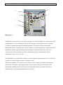
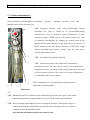
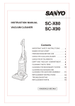
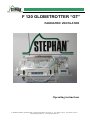
F 120 GLOBETROTTER “GT”
PAEDIATRIC VENTILATOR
Operating instructions
F. STEPHAN GmbH ⋅ Medizintechnik ⋅ D-56412 Gackenbach ⋅ Kirchstr. 19 ⋅ Tel. (06439) 9125-0 ⋅ Fax (06439) 9125-11
[email protected] ⋅ www.stephan-gmbh.com
Reanimator F 120 GT
Realisation:
Bernd Höhne
Edited John Hussen
F. Stephan GmbH
-MedizintechnikGackenbach
Subject to technical changes
Status: February 2006
Rev.: 2.1
Operating instructions
2
Reanimator F 120 GT
Operating instructions
3
Content
1. NOTICE......................................................................................................................................................5
2. PREFACE ..................................................................................................................................................6
Optional Monitoring ................................................................................................................................................... 7
3. RANGE OF APPLICATION.......................................................................................................................8
4. SPECIFICATIONS OF THE REANIMATOR F 120 GT.............................................................................9
5. PRINCIPLE OF PERFORMANCE...........................................................................................................11
6. DESCRIPTION OF PERFORMANCE. ....................................................................................................13
External Oxygen Supply – Incubator ...................................................................................................................... 19
7. DESCRIPTION OF CONTROL ELEMENTS AND ELEMENTS .............................................................20
7.1 Twin flowmeter.................................................................................................................................................... 20
7.2 O2- Monitor ....................................................................................................................................................... 21
7.3 Control component and indicators .................................................................................................................... 22
7.4 Monitor................................................................................................................................................................. 23
7. 5 Patient component P1 ....................................................................................................................................... 24
7.6 Patient tube system.............................................................................................................................................. 27
8. TESTING PRIOR TO OPERATION.........................................................................................................29
8.1 Monitoring ........................................................................................................................................................... 29
8.2 Inspiratory pressure (Plateau), expiratory pressure (PEEP) .......................................................................... 29
8.3 Tightness .............................................................................................................................................................. 29
8.4 Heater and tube heating system ......................................................................................................................... 30
8.5 O2-Monitor .......................................................................................................................................................... 30
8.6 Intake filter .......................................................................................................................................................... 30
9. DESCRIPTION OF MODES OF VENTILATION .....................................................................................31
9.1 Controlled ventilation, IMV ............................................................................................................................... 31
Reanimator F 120 GT
Operating instructions
4
9.2 Manual ventilation and inflation........................................................................................................................ 32
9.3 CPAP - ventilation............................................................................................................................................... 33
10. CLEANING AND STERILIZATION .......................................................................................................34
11. INSPECTION AND MAINTENANCE.....................................................................................................35
12.
ACCESSORIES LIST / SPARE PARTS F 120 GT ..........................................................................36
F120GT Ventilator Replacement Part..................................................................................................................... 36
NeoSid Monitor Accessories + disposables.............................................................................................................. 36
Reanimator F 120 GT
Operating instructions
5
1. NOTICE
1. Pursuant to Medical Device Directive 93/42, the apparatus must only be operated by
trained personnel. Prerequisite is an exact knowledge of the operating instructions.
2. The apparatus is only intended for use as specified in the operating instructions.
3. The apparatus must be inspected periodically by trained personnel.
4. The F. STEPHAN GmbH prescribes a semi-annual inspection and maintenance by an
authorised service technician.
5. A performance test has to be carried out prior to each putting into service.
6. The F. STEPHAN GmbH will not be liable for damages resulting from faulty operation due to
non-observance of the operating-instructions or from use, for which the apparatus is not
earmarked.
7. If possible, neither antistatic nor electrically conductive tubes should be used.
8. Prior to each putting into service a performance test has to be carried out by activating the key
„AUTO TEST“. In doing so, all luminous fields must illuminate, an intermittent audible alarm
must sound five times and the valve must be activated five times.
9. An apparatus for manual ventilation, independent from the Reanimator F 120 GT must be close
at hand.
10. The Reanimator F 120 GT must only be operated with the genuine by-pack spare-parts of
STEPHAN or with those parts, which are recommended by the manufacturer.
11. The conveying capacity of the built-in compressor changes with 12 V (DC) operation.
WARNING
The Reanimator must not be used with, respectively in connection with inflammable
anaesthetic agents.
If the ambient temperature rises above 41°C the humidifier heater should be switched off
The Reanimator F 120 GT is provided with an internal battery. To guarantee an optimum
charge of the battery, the apparatus must always be connected to the current supply and
mains switch on the apparatus plug must be in „ON“-position during stand-by periods.
With an optimum charge of the battery, an operating time of at least 2 hours is secured. The
time to recharge the discharged battery takes at least 20 h.
NOTE:
An external 12v supply can be connected using the external dc cable.
Reanimator F 120 GT
Operating instructions
6
2. Preface
The STEPHAN Reanimator is a ventilator unit for neonatal and perinatal short-term ventilation. It
operates time-controlled, flow-constant and pressure-limited for controlled IMV-ventilation as
well as flow-constant and pressure-limited for CPAP-ventilation and manual ventilation.
Inspiration time is adjustable from 0.25 to 2 seconds; expiration time is adjustable from 0.25 to 30
seconds. Flow is adjustable from 0 to 20 l/min; respiratory pressure is adjustable from 15 to 60
cmH2O
The frequency indicator (digital) indicates, according to the setting, with controlled ventilation
(IMV) the respiratory rate of 2 to 120 breaths per minute (BPM). In operating mode CPAP the
display shows three bars (---).
Oxygen and air are mixed in the attached twin flowmeter. Oxygen concentration is adjustable
from 21 to 100% O2. An O2-monitor with adjustable minimum- and maximum alarm-value
monitors the oxygen concentration with visual and audible signals.
The monitor supervises visually and audibly failure of mains power and gas supply as well as
disconnection and stenosis. As well as the Auto-Test system the electronics of the respirator are
permanently supervised by a Watchdog system.
The apparatus is provided with a heater for warming the respiratory gas. The heater consists of the
heater cartridge for humidification of the respiratory gas as well as of the heated tube system to
stabilise temperature and to prevent forming of condensate water. The heating system can be
switched on and off.
The patient component P 1 consists of the heated humidifier for the respiratory gas, PEEP- and
inspiration-pressure valve and can be autoclaved at up 134°C. A compressor is integrated in the
Reanimator F 120 GT, making a self-supporting supply with compressed air possible. It directly
and permanently supplies the F 120 GT so that no external supply with compressed air need be
connected. In addition to the 230 V mains supply it is possible to connect the F 120 GT to an
external electric board network and to operate the Reanimator on 12V (DC). An internal battery
provides the power supply, when no mains supply, respectively board network is available.
Switching over to the available power supply ensues automatically and is indicated.
Reanimator F 120 GT
Operating instructions
7
Optional Monitoring
The F 120 GT can be equipped with an optional Monitor NeoSid plus. This monitor is able to
measure heart- and respiration signs of the patient during transportation.
The EKG- and respiratory signals and are detected due to electrodes attached to the body of the
patient.
By using the unique Massimo technology oxygen saturation of the patient is detected and
controlled.
The large, backlit display is able to show digital information as well as graphical indication by
means of SpO2-, EKG- and respiration-impedance curves.
Reanimator F 120 GT
Operating instructions
8
3. Range of application
The Reanimator F 120 GT is a ventilator for short-term and emergency ventilation of premature
infants, neonates and infants.
It is used in the case of insufficiency in the lungs of neonates due either to immaturity, disease or
failure of the respiratory system.
Due to the independence of any distribution voltage the Reanimator F 120 GT is designed to be
operated as part of the TI 5000 Globe Trotter Neonatal Transport System.
The internal battery provides an operation-time of at least 2 hours independent from distribution
voltage at max loading capacity.
Caution:
The Reanimator F 120 GT is not designed for long term intensive care ventilation.
Reanimator F 120 GT
Operating instructions
9
4. Specifications of the Reanimator F 120 GT
Modes of operation:
-IMV (controlled ventilation)
-CPAP (spontaneous respiration)
Possible settings:
Inspiration time adjustable
0,25 to 2 seconds
Expiration time adjustable
0,25 to 30 seconds
O2-flow (constant) adjustable
0 to 10 l/min
Air-flow (constant) adjustable
0 to 10 l/min
Oxygen concentration adjustable
21 to 100% O2
Patient component
Expiratory pressure (PEEP) adjustable
0 to 15 cmH2O
Inspiratory pressure (Plateau) adjustable
15 to 60 cmH2O
Heated humidification
12 V 10 Watt
Heated tube system
Power consumption
12 V 10 Watt
Monitor
Disconnection
Visual and audible alarm in case 12 cmH2O are not
reached after expiration time + maximum
inspiration time
Stenosis
Visual and audible alarm if respiratory pressure
does not fall below 12 cmH2O
2,2 seconds after end of inspiration time
Failure of power supply:
Audible alarm for 120 seconds
Fault of Reanimator-electronics:
Visual and audible alarm until fault has been
eliminated.
Distribution voltage:
Indication of the actual distribution voltage
Testing program „AUTO-TEST“:
Performance test of all indicators, alarms and of the
valve.
Mute of alarm:
2-min suppression of audible alarm
Reanimator F 120 GT
Operating instructions
10
Oxygen-monitor
Digital display:
21 to 99% O2 of the respiratory gas
Maximum O2-limitation adjustable:
21 to 99% O2, visual and
Audible warning in case of exceeding.
Minimum O2-limitation adjustable:
21 to 99% O2, visual and audible warning in
case of falling below.
Automatic calibration:
Only in case of saturation with compressed air.
Indicators:
Respiratory pressure, gauge
-10 to 60 cmH2O
Frequency with IMV (digital)
2 to 120 respirations per minute (BPM)
Power supply:
230V/50 mains
12V (DC) external
12V (DC) internal by battery
Protective transformer:
Single phase separating transformer, power
consumption 70 VA
Protective class:
I Type B
Protective category:
IP2O
Weight:
app. 18 kg
Measurements:
L 120 x H 300 x D 210 mm
Reanimator F 120 GT
Operating instructions
11
5. Principle of performance
The Reanimator F 120 GT primarily works time-controlled and pressure-limited according to the
continuous-flow-principle. The fresh gas, as set on the flowmeter unit, flows during inspiration
and expiration. To avoid unintended adjustments of the gas flow the knobs of the flow control
valves are different due to the gas type and are covered by a metal frame.
The filling of the lungs during inspiration is accomplished by closing of the expiration valve.
For manual ventilation, the expiration valve can be closed by hand pushing the red button of the
expiratory valve. If the set inspiratory pressure limit - inspiratory pressure plateau - is reached
prior to the end of the selected inspiration time, the surplus gas is evacuated via the mechanical
inspiratory pressure valve.
A second safety valve to avoid excessive patient gas pressures is positioned at the rear of the F
120 GT. It is set to 40 cmH2O at a gas flow of 5 l/min.
Expiration is effected by opening the expiration valve. Hereby the lungs evacuate due to the
decrease of pressure. Expiratory gas and fresh gas together are evacuated via the expiration valve.
From this results the following important consistency, common to all constant-flow-appliances:
The set continuous gas flow bypasses even during the expiration cycle the y-piece of the patient.
That bypass flow washes out the exhaled carbon dioxide (CO2) of the patient.
The rate of the gas flow should be adjusted minimum to the inspiratory peak flow of the patient
(approx. 2-5 l/min ). Excessive gas flows will increase the work of breathing of the patient, as
does too low a gas flow.
The minute volume as set on the flowmeter unit is the maximum quantity of fresh gas available to
the patient for the period of one minute. Dependent on the set respiratory cycle (inspiration time +
expiration time, respiratory time ratio) the patient receives only part of the set minute volume,
since part of the fresh gas is lost during expiration and when the pressure plateau has been reached
and consequently is no longer available to the patient. From this follows, that the set minute
volume on the flowmeter unit must always be higher than the inspiratory minute volume that the
patient is supposed to receive.
Reanimator F 120 GT
Operating instructions
12
Dependent on the system this results, according to the set flow, in an increase of the endexpiratory pressure, indicated on the pressure gauge.
Due to the danger of hyperextension of the lungs of babies and infants, ventilation with pressure
limitation is decisive. To administer a sufficient volume of gas under this limitation, a constant
flow is offered. This may be more than the patient is able to take in. Therefore, different
respiratory patterns may result.
High gas
flow
Flow 10
l/min
Flow 10
l/min
8
8
6
6
4
4
2
2
Insp.time
Low gas flow
Insp.time
Time / s
Press. 50
/ cmH2O
Time / s
Press. 50
/ cmH2O
Pressure
limitation due
to insp. valve
40
30
40
20
20
10
10
Insp.time
Time / s
Lower insp.
Press. due to
low gas flow
30
Insp.time
Time / s
With an increased offer of flow, the pressure limit is reached fast; here the airway resistance
caused by the development of turbulences becomes especially perceptible. Flow in the trachea
remains on a uniform high level only for a short period of time, since the lungs with low
compliance keep filling.
With a low offer of gas flow the set pressure limit is reached later. Here the compliance of the
lungs is decisive. It takes a longer time until the pressure limit is reached and the flow, which in
this case develops less turbulence, remains almost constant through a long period of the
inspiration time.
Reanimator F 120 GT
Operating instructions
13
6. Description of performance.
The Reanimator must be connected to the mains 230 V by means of the apparatus plug (picture1/
item1) and the attached connecting cable. The mains switch (1/2) should always be switched on,
so that the internal battery can be charged during endurance.
1
2
3
Illustration 1
Additionally the F 120 Mobil can be connected to a 12V onboard supply by means of the 12Vplug (1/3) with the by-packed connection cable.
With the reception coupling and the connecting tube the F 120 Mobil must be directly connected
to the oxygen supply. The air pressure supply is provided by the built-in compressor. With the
ON/OFF switch the apparatus is switched on.
The Paediatric-Reanimator F 120 GT is a time-controlled and pressure-limited constant-flow
ventilator, developed for first care and emergency ventilation of babies and infants.
Reanimator F 120 GT
Operating instructions
14
6
1
2
3
4
5
Illustration 2
The Reanimator F 120 GT is connected directly to the central oxygen supply or to the integrated
oxygen cylinder of the incubator. The high pressure gauge (2/2) informs you about the cylinder
content. The low pressure gauge (2/3) informs you about the oxygen pressure of the internal
pressure reducer or the wall supply.
The built-in compressor of the apparatus effects supply with compressed air. The level of the
fresh-gas-flow and the oxygen concentration are set by means of the two proportioning valves
(2/4, 2/5) in constant-flow mode. After connecting the power-supply, the apparatus is switched on
with the ON/OFF -switch (2/1). After switching off, the F 120 GT saves the last operation mode
and starts with this mode, when the Reanimator is switched on again. For example, if he starts in
IMV-mode, controlled mandatory ventilation cycles are delivered to the patient, in accordance
with the set parameter for inspiration and expiration.. During inspiration the expiration valve (2.6)
is closed and so the lungs of the patient are inflated. By switching over into expiration this valve
opens and the air can escape from the lungs.
Reanimator F 120 GT
Operating instructions
15
5
1
2
Illustration 3
3
4
A positive end-expiratory pressure (PEEP) can be set by means of the expiration valve (3/1). It
acts mechanically via the set force of pressure of a spring.
The inspiration valve (3/2) is a purely mechanical valve and serves to limit the respiratory
pressure (Limitation of inspiratory pressure). If the set pressure is exceeded, the inspiration valve
opens (inspiratory plateau) and the surplus fresh gas can escape into ambient air and no longer
reaches the lungs of the patient.
The switching cycle of the expiration valve can be set by means of coding switches for inspiration
(3/3) and for expiration (3/4). The respiratory time ratio results automatically from the settings of
inspiration and expiration. Respiratory frequency is calculated from the set parameter and
displayed digitally in the three-digit display (3/5).
Reanimator F 120 GT
Operating instructions
1
16
2
Illustration 4
The keys 4.1 and 4.2 serve to change the mode of ventilation. By depressing the key for CPAP
(4/2), the apparatus is switched over into the spontaneous breathing mode. In doing so, the
expiration valve is always open. The patient can now breathe spontaneously, using the offered
flow of fresh gas. Furthermore, an end-expiratory pressure (PEEP) can be adjusted by means of
the expiration valve (3/1, shown on the previous page). After depressing the key IMV (4/1) the
ventilation mode returns to controlled ventilation (“Intermittent Mandatory Ventilation” = IMV).
Reanimator F 120 GT
Operating instructions
17
1
6
3
5
2
4
Illustration 5
With the key for the heater (5/1) the heater cartridge (5/2) in the humidifier for respiratory gas and
the heated tube (5.3) are switched on and off. The fresh gas is warmed by the heater cartridge
(5/2) and is conducted through the humidifying bottle (5/4), which is filled with distilled,
demineralised water. The heated tube system maintains a constant temperature of the warmed and
humidified respiratory gas and thus prevents forming of condensate water in the tube. The
elements of the heater cartridge and of the tube heating system are dimensioned so that a
temperature of app. 35-36°C results.
The Reanimator is provided with a monitor for supervising the respiratory pressure (5/5) and with
a monitor for supervising the oxygen concentration (5/6).
The pressure monitor (5/5) warns in case of failure of power supply, gas supply, disconnection
and stenosis. The failure-of-gas-supply-alarm, respectively the stenosis alarm sounds, if the
permanently installed pressure limit is not exceeded by the respiratory pressure after the set
expiration time + maximum inspiration time (2 seconds).
Reanimator F 120 GT
Operating instructions
18
Stenosis alarm activates, if respiratory pressure does not fall below the permanently installed
pressure limit 2,2 seconds after end of inspiration. The oxygen monitor (5.6) supervises the
concentration of oxygen in the respiratory gas.
lllustration 6
The O2 monitor can be switched on and off by means of the ON/OFF-key.
The O2-sensor is plugged into the gas stream at the front. An upper alarm limit and a lower alarm
limit can be set with the help of the coding switches. The alarm limits are activated only with the
O2-monitor switched on. In the event that the oxygen
concentration level rises above or falls below the selected
set points an audible and visual alarm occurs
The O2 monitor has to be calibrated anew from time to time
for 21% oxygen, using the Cal.-key. To do so, it is
necessary to place the O2-sensor in ambient air.
Note: If it is necessary to measure the O2-concentration
of the incubator you can remove the sensor from its
measurement socket and close the socket with the blue
replacement plug.
Oxygen sensor
replacement plug
Reanimator F 120 GT
Operating instructions
19
The audible alarm of all monitor functions can be muted for 2 minutes by means of
the „2-min-key“.
Prior to every putting into service, a performance test has to be carried out by depressing the key
„AUTO TEST“. Hereby all luminous fields must illuminate, intermittent audible alarms must
sound five times and the valve must activate five times.
The loading capacity of the internal battery as well as the 12 V-on-board-supply is supervised.
When the minimum supply is falling short, every 30 seconds a warning tone is released. It can not
be suppressed and the equivalent potential indicator starts flashing.
As of this time, 20 minutes operation time remains. If the power supply falls below a critical level,
the apparatus is automatically shut off.
External Oxygen Supply – Incubator
It is possible to adjust an oxygen flow to the incubator or any other application where an
adjustable oxygen flow is needed.
To do so you can open the additional oxygen valve at the front of the F 120 GT. It will allow the
application of oxygen flows stepwise from 0.5 l/min up to 25 l/min.
An ISO-connector can be directly screwed to the outlet of the oxygen valve.
If the air inside of the incubator should be enriched with oxygen, it is possible to measure the
concentration with the oxygen monitor of the F 120 GT.
Oxygen
valve
ISO-connector
Oxygen valve
Reanimator F 120 GT
Operating instructions
20
7. Description of control elements and elements
7.1 Twin flowmeter
Illustration 7.1
7.1
Twin flowmeter for mixing the respiratory gas and
for
setting of flow.
AIR
O2
7.1/1 Proportioning valve for setting oxygen concentration of the
respiratory gas. With increased flow the oxygen
Concentration increases automatically. I.e. in case of
constant flow, compressed air must be reduced
Proportionally to the increase of oxygen flow. O2concentration can be monitored on the O2-monitor.
l / mi n
A IR
O2
7.1/2 Proportioning valve for setting the fresh gas flow. With
increase of the fresh gas flow by means of the
Proportioning valve (7.1/2) oxygen concentration
1
7.1
2
decreases.
To reach the optimum mixture of respiratory gas with a determined flow, the correct setting must
be found by alternating rotation of the proportioning valves (Control of the O2-monitor).
Reanimator F 120 GT
Operating instructions
21
7.2 O2- Monitor
7.2
O2Monitor
%
C AL
21 %
1
0
7.2
1
O2-monitor for monitoring of oxygen concentration in the fresh
gas.
7.2/1 Digital display of O2-concentration.
7.2/2 Calibration key for adjusting the sensor to 21% O2 with
2
ambient air. The sensor is permanently installed in the
3
Reanimator. During calibration the sensor must only be
O 2 m ax
-
4
saturated with compressed air. I.e. the proportioning valve for
oxygen on the flowmeter (2/5 shown on page 14) must be
9 9
rotated to its right stop, so that the supply with oxygen is cut off.
+
O 2 mi n
7.2/3 ON/OFF-switch of O2-monitor.
-
2 1
5
+
Illustration 7.2
7.2/4 Coding switch for setting the minimum oxygen concentration. If the oxygen concentration
falls below the selected set point an audible and visual alarm occurs.
7.2/5 Coding switch for setting the maximum oxygen concentration. In case of exceeding
this limit a visual and audible alarm occurs.
A visual and audible alarm ensues, if the set limit values are exceeded or fallen below. By
means of the key "2 min” the audible alarm can be muted for 2 minutes. The visual alarm
ceases only after the fault has been eliminated.
Reanimator F 120 GT
Operating instructions
22
7.3 Control component and indicators
2
3
5
6
4
1
8
7
9
7.3/1 Timer for setting the respiration times (inspiration and expiration) as well as indication
of the respiratory frequency. Setting of the respiration times and indication of the
respiratory frequency is activated only in connection with the ventilation mode IMV
(7.3/2). With ventilation under CPAP (7.3/3) the display shows three bars (---).
7.3/2 Key for changing to ventilation mode of controlled ventilation (IMV)
7.3/3 Key for changing to ventilation mode of spontaneous ventilation (CPAP)
7.3/4
ON/OFF-switch of Reanimator F 120
7.3/5 Key for switching the heater on and off (humidifier of the respiratory gas, tube heating
system)
7.3/6 Key for starting AUTO-TEST of Reanimator. Hereby the performance of all input- and
output elements is tested.
7.3/7 Coding switch for setting the inspiration time.
7.3/8 Indication of respiratory frequency with IMV. The frequency is calculated from the
settings of inspiration time and expiration time.
7.3/9 Coding switch for setting the expiration time.
Reanimator F 120 GT
Operating instructions
23
7.4 Monitor
Monitor for supervision of the respiratory pressure. Activated only with ventilation mode IMV.
Stenosis
Visual alarm occurs if the pressure does not fall below the
limit of 12 cmH2O 2.2 seconds after the end of inspiration
Disconnection
Visual alarm ensues, if the
permanently installed pressure limit of 12 cmH2O is not
exceeded after the set expiration time + maximum
inspiration time (2.0 sec), (Failure of gas supply,
disconnection).
O2-Alarm
Visual alarm occurs when the set values for
oxygen concentrations are violated. Alarm activates
only when the oxygen monitor is switched on.
Mute Key for muting the audible alarm for 2 minutes. By
pressing, all audible alarms are muted for 2 minutes,
whereby the visual alarms remain active. If the alarm
condition still persists after 2 minutes, the audible
alarm will be released again. Audible and visual
alarm cease only, when the cause for the alarm has
been eliminated.
BAT.
Indication of supply voltage for 12V (DC), internal accumulator.
12 V ext.
Indication of supply voltage for 12V (DC), external.
Mains
Indication of supply voltage for 230V/50 Hz (AC)
Reanimator F 120 GT
Operating instructions
24
7. 5 Patient component P1
Patient component with limitation of inspiratory
pressure,
expiration
pressure
valve
and
humidification of the respiratory gas.
1
7.5/1 Expiratory pressure valve with PEEP-setting. During
inspiration, the valve is closed by an electromagnet,during
expiration the valve is currentless (open). Furthermore, an endexpiratory pressure (PEEP) can be set by means of this valve. This
is performed mechanically by rotating the control knob in the
appropriate direction. Rotation to the right effects an increase of
PEEP, rotation to the left effects a decrease of PEEP.The setting
must be controlled on the pressure
gauge, since the scale values
are only approximate values.
2
7.5/2 Push-button for manual ventilation.
3
7.5/3 Inspiratory pressure valve (Plateau) for limitation of
respiratory pressure. The valve acts as a safety valve and limits the
inspiratory pressure. According to the setting of inspiration time and
of flow a plateau at the level, set on the valve, forms. Setting must
be controlled on the pressure gauge.
4
6
7.5/4 Fastening screw, for fastening the complete patient
component of the Reanimator.
5
Illustration
7.5
7.5/5 Humidifier bottle for saturation of the warmed fresh gas with water vapour. The relative
humidity then amounts to approximately 85 to 95% at the outlet of the humidifier.
7.5/6 Heater cartridge with bubbling tube for warming the fresh gas. Hereby the fresh gas is
conducted through the bubbling tube and past the heater cartridge, where it is warmed
and then led into the humidifier bottle.
Only distilled and demineralised water must be used.
Reanimator F 120 GT
Operating instructions
25
Reanimator F 120 GT
Operating instructions
26
If the patient component is removed a protective cap to prevent damages to the
connections and contacts during cleaning and transportation should be used. For
attachment of the patient component to the Reanimator, the protective cap has to be
removed.
The Connection taper for the inspiration and expiration tubes are positioned at the left
side of the patient component.
Between the tapers are the sockets to connect the heating of the tube system.
Notice:
Use only distilled water for the humidifier bottle. Do not fill beyond the filling mark. Do not fill
with inflammable anaesthetic agents. Test humidifier bottle for tightness after disinfection or
sterilisation.
Reanimator F 120 GT
Operating instructions
27
7.6 Patient tube system
7.6 Heated patient tube system, consisting of the
two silicone tubes with heater spiral for inspiration
(7.6/2) and expiration (7.6/1). The heater spiral
serves to stabilize temperature and to prevent
theformation of condensate water. For ventilation in
the incubator, only the unheated ends of the tube
system are introduced in the incubator. If the
temperature of the incubator is lower than the
nominal temperature of the respiratory gas,
condensate water may form in the unheated ends of
the tube system. The tube heating system is plugged
into the patient component by inserting the plugs
7.6/3) and (7.6/4) into the sockets of the patient
component.
Illustration 7.6
7.6/1 Heated expiration branch of the tube system.
7.6/2 Heated inspiration branch of the tube system.
7.6/3 Connection plug of heater spiral of the expiration branch. To be inserted into the
provided
connection socket of the patient component.
7.6/4 Connection plug of heater spiral of the inspiration branch. To be inserted into the
provided connection socket of the patient component.
7.6/5 Y-piece, connects inspiration branch and expiration branch of the tube system with the
patient.
7.6/6 Tube connector for connection of ventilation tube with the Y-piece. With the help of it,
the
ventilatory deadspace is significantly reduced.
7 6/7 Face mask for short-term ventilation and reanimation. Available in sizes 1 to 3.
Reanimator F 120 GT
Operating instructions
28
Reanimator F 120 GT
Operating instructions
29
8. Testing prior to operation
8.1 Monitoring
After switching the reanimator on and depressing the test-key, all indicator elements and the
performance of the expiration valve (switching on five times) are tested. The disconnection
monitor activates visually and audibly, after 20 seconds, a short continuous tone sounds. In case of
a fault, the audible alarm persists and is illuminated.
The disconnection monitor is permanently set at 12 cmH2O this pressure value must be exceeded
with every respiratory cycle performed by the apparatus, otherwise alarm is released. With help of
the Stand-by-key the audible alarm of the monitor can be muted for 2 minutes. The stenosis
monitor is tested by means of building-up of pressure. If the pressure does not fall below the
pressure limit of 12 cmH2O 2.2 seconds after the end of inspiration, visual and audible alarm
ensues.
8.2 Inspiratory pressure (Plateau), expiratory pressure (PEEP)
The plateau regulator, limiting the inspiratory pressure, is tested by connecting the tube system to
the Y-piece.
The pressure gauge then must indicate the set inspiratory pressure.
PEEP is set on the inspiration valve by means of the control knob. The tube system is occluded on
the Y-piece.
At the end of inspiration, the pressure gauge must then indicate the set PEEP.
8.3 Tightness
Especially in the paediatrics, the tightness test is of great importance. With the Y-piece occluded,
the inspiratory pressure, set at min. 40 cmH2O with a flow of 5 litres per minute, must exceed 30
cmH2O in the set inspiration time of 1,0 seconds.
Reanimator F 120 GT
Operating instructions
30
8.4 Heater and tube heating system
Test of the heating system can only be performed by manual control. After switching the heater
on, the humidifier and the tube heating system will feel warm to the touch (33 to 34°C).
8.5 O2-Monitor
The oxygen concentration set on the flowmeter is displayed digitally. To test the visual and
audible alarm, the oxygen concentration is first adjusted to a value exceeding the set maximum
limit value and then to a value falling below the set minimum limit value. In both cases visual and
audible alarm must be released.
8.6 Intake filter
Prior to any putting the apparatus into service, the intake filter should be checked and if required
exchanged.
Reanimator F 120 GT
Operating instructions
31
9. Description of modes of ventilation
9.1 Controlled ventilation, IMV
Inspiration- and expiration times are pre-selected by the user in values of seconds. From this result
the respiratory frequency (RF= 60 seconds/(inspiration time + expiration time)) and the
respiratory time ratio (I/E inspiration time/expiration time).
The following settings are possible:
Inspiration time of 0,25 to 2 seconds
Expiration time of 0,25 to 30 seconds
From this result the possible respiratory frequencies of 2 to 120 BPM. This value is displayed
digitally.
Example
Insp. time 1,0 sec. exp. time 2,0 sec.:
RF (l/min) = 60 sec. /(1,0 sec. + 2,0 sec.)= 20/min
2 x Inspir. = 1 x Expir.
Inspiration/expiration = 1/2
I : E ratio = 1 : 2
Since the flow of gas is not interrupted during expiration, the patient is able to breathe
spontaneously at any time. The controlled respirations released by the apparatus ensue
unsynchronised, i. e. also during spontaneous inspiration, respectively expiration. Premature
infants and neonates easily tolerate this.
Reanimator F 120 GT
Operating instructions
Ti Total
32
Te
In ventilation mode IMV the expiration valve is closed during the set inspiration time and is
opened after elapse of the set expiration time. Frequency is displayed digitally. Level of the
respiratory flow is set on the flowmeter in relation to the lungs to be ventilated. The flow is
constant during inspiration- and expiration phase. The resulting positive insp pressure PIP can be
limited by means of the inspiratory pressure valve (Plateau). This inspiratory pressure plateau
remains constant for the duration of inspiration. During this time, the gas can spread in the lungs
under a constant pressure. The patient is able to breathe spontaneously between the respirations
delivered by the apparatus (IMV). If the expiration time (Ti) is further extended the portion of
spontaneous respirations increases. An expiration time (Te) of maximum 13 seconds results in a
frequency of about 4 to 5 respirations per minute. The built-in monitor adapts itself automatically
to the change of expiration time. This means however, that alarm, for example in case of
disconnection, is released then only after 15 seconds. Nevertheless, just for this reason an IMVventilation with a frequency of 4 to 5 BPM should be preferred to the normal CPAP-ventilation,
since the pressure monitor of the F 120 GT is not activated during CPAP-ventilation and also no
apnoea-alarm will be released. During controlled ventilation, depressing the key for manual
ventilation can produce an artificial sigh or a prolongation of inspiration.
9.2 Manual ventilation and inflation
By depressing the red push-button the expiration valve is closed mechanically for the duration of
depression. During CPAP-ventilation the patient can be ventilated manually or inflated by
depressing the push-button. Hereby the respiratory pressure as set on the inspiratory pressure
valve (Plateau) is built up.
Reanimator F 120 GT
Operating instructions
33
9.3 CPAP - ventilation
Due to the continuous-flow principle, a genuine CPAP-ventilation is possible. The PEEPmechanism in the expiration valve always maintains the set end-expiratory pressure in the
constantly flowing gas.
P/cmH2O
Spontaneous breathing patient
CPAPLevel
Insp.tim
Exp.tim
Spont. Breathing
t/s
With this flow of gas, the patient is able to breathe spontaneously under a positive pressure.
This PEEP-valve can be used for all modes of ventilation.
With sufficient spontaneous respiration the patient can breathe spontaneously in the CPAP mode
of ventilation. After depressing the key CPAP the expiration valve is switched currentless (open)
and the monitor is out of operation. The flow is adapted to the spontaneous respiration, so that the
motions of inspiration and expiration can be read off at the pressure gauge. Expiratory pressure
PEEP is set at the desired pressure of 1 to 10 mbar. A monitor should be used to supervise apnoea
and disconnection.
If the disconnection monitor of the respirator is supposed to keep operating, switching over to
IMV with long expiration time if necessary.
Reanimator F 120 GT
Operating instructions
34
10. Cleaning and sterilization
All components that have contact with the patient like the patient component and the patient tube
system are detachable for cleaning purposes.
The following parts can be autoclaved at 134°C:
-
Patient component P1, complete with heater cartridge and humidifier bottle.
-
the heated tube system of the patient tube system .
-
the Y-piece
The following parts can be sterilized in a sterilizing solution or by means of gas sterilization:
-
the tube connector
-
- the face mask
When the patient component is unscrewed from the F 120 GT for cleaning or sterilization
(loosening of the fastening screw ), the protective cap must be fastened to the patient component
with the fastening screw . The humidifier bottle must be unscrewed to make a separate
sterilization possible.
The intake filter for the compressed-air-supply at the rear of the apparatus must be checked prior
to any putting into operation. In case of accumulation of dirt it must be cleaned, respectively
exchanged.
Important:
Especially after sterilization in a dissolvent, care has to be taken that no sterilizing agent
remains in the component parts.
All parts must be allowed to drip off and dry.
Reanimator F 120 GT
Operating instructions
11. Inspection and maintenance
Maintenance by operating technicians
The silicone-ring on the connection nipple of the patient component must be checked and
exchanged if defective.
The intake-filter must be cleaned, respectively exchanged.
Service and repairs
Service and repairs must only be carried out by the
F. Stephan GmbH
Medical Engineering
Kirchstr. 19
D - 56412 Gackenbach
or by personnel who have been trained and authorized by the F. Stephan GmbH.
35
Reanimator F 120 GT
12.
Operating instructions
Accessories list / spare parts F 120 GT
Part No.
1-002-61-001
1-002-61-512
1-705-50-056
1-950-60-003
1-951-60-001
1-002-61-020
1-650-40-005
1-002-61-016
1-701-60-416
Accessories
Patient component P1 (heated)
Patient hose system w/y piece (heated)
power pack-Atmos suction pump
O-ring 4 x 1.5
Flat gasket humidifier bottle 300 ccm
Teflon sleeve long complete for patient comp. P1/P2/P3
Humidifier bottle 300 ccm
Protection cap P1/P2/P3 complete
Y-Piece with rubber cap
F120GT Ventilator Replacement Part
1-804-60-002
1-802-60-406
1-34-61-412
1-107-60-008
1-107-60-009
1-107-60-010
1-950-60-009
Set of fuses 5x20 mm
Power connection cable 230 V
Power connection cable 12 V
Connection cable for oxygen sensor
Oxygen sensor
Diffuser for oxygen sensor
O-Ring for diffuser
NeoSid Monitor Accessories + disposables
1-702-60-010
1-702-60-011
1-702-60-013
1-702-60-025
1-702-60-020
1-702-60-019
1-704-60-122
1-704-60-123
1-704-80-124
Gel electrodes (VE 240 pc(s)) 30mm
Gel electrodes for allergic persons (VE 240 pc(s)) 30mm
electrodes without gel (VE 240 pc(s)) 30mm
Patient cable for NeoSid
Long-life electrodes (VE 3 pc(s))
Adhesive rings for Long-life electrodes (VE 500 pc(s))
Flexsensor for infants< 10kg, disposable
Flexsensor for infants with sensitive skin< 1kg-disposable
Flexsensor for paediatrics 10-50kg-disposable
36