1
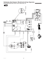
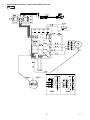
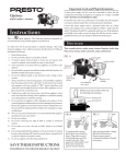
0595J01900
Coupe-légumes
09/2011
Vegetable preparation machine
Gemüseschneider
Manuel d’utilisation - Notice originale
User manual - Translation of the original instructions
FR
GB
Gebruikshandleiding - Vertaling van de originele handleiding
DE
IT
NL
Användningsmanual - Översättning av den originala bruksanvisningen
SE
Brugervejledning - Oversættelse af de oprindelige brugsanvisninger
DK
NO
Bedienerhandbuch - Übersetzung der Originalanleitung
Manuale di utilizzo - Traduzione delle avvertenze originali
Brukerhåndbok - Oversettelse av den originale bruksanvisningen
Manual de Utilização - Tradução das instruções originais
FI
ES
PT
Εγχειρίδιο χρήσης - Μετάφραση των αρχικών οδηγιών χρήσης
EL
Käyttöohjekirja - Alkuperäisen ohjeen käännös
Manual de utilización - Traducción del manual original
TRS FR 11 00
TRS FR 5 98
TRS FR 4 98
This document is to be used in conjunction with the original manufacturer’s manual.
The symbols correspond with the numbered drawings of the original manual.
GB
09/2011
Contents
Introduction
Installation
Use, safety
Cleaning, hygiene and storage
Fault finding
Maintenance
Conformity with regulations
1
1
2
4
4
4
5
Introduction
The User Manual contains useful information for the user on
how to work correctly and in complete safety, and is designed
to make it easier to use the machine (called «machine» or
«appliance» below).
What follows is in no case intended to be a long list of warnings
and constraints, but rather a series of instructions meant to
improve the service provided by the machine in every respect,
and particularly to avoid a series of injuries or damage to equipment that might result from inappropriate procedures for use
and management.
It is essential that all the people responsible for transporting,
installing, commissioning, using, maintaining, repairing or dismantling the machine should consult this manual and read it carefully
before proceeding with the various operations, in order to avoid
any incorrect or inappropriate handling that might be result in
damage to the machine or put people’s safety at risk.
It is just as important that the Manual should always be available
to the operator and it should be kept carefully where the machine
is used ready for easy and immediate consultation in case of any
doubt, or in any case, whenever the need arises.
If after reading the Manual, there are still any doubts concerning
how to use the machine, please do not hesitate to contact the
Manufacturer or approved After Sales Service provider, who
is constantly available to ensure quick and careful service for
improved machine operation and optimum efficiency.
Note that the safety, hygiene and environmental protection standards currently applicable in the country where the machine is
installed must always be applied during all phases of machine
operation. Consequently it is the user’s responsibility to ensure
that the machine is operated and used solely under the optimum
safety conditions laid down for people, animals and property.
Introduction
1.1 DESCRIPTION
The multi-purpose vegetable cutting machine can slice, shred,
grate, chip and dice various foodstuffs (for the preparation of
raw and cooked vegetables, fruits and cheeses).
With its range of high output cutters, the machine is the professional vegetable cutter for restaurants, large kitchens and
small companies.
1.1
Installation
A
B
C
D
E
F
G
H
I
J
K
Body
Stop button (red)
Start button (black)
Feed stick
Feed arm
Large feed hopper
Cover
Discharge chute
Cover lock
Feet
Plastic of stainless steel housing, depending
on models
2.1 DIMENSIONS - WEIGHT (for information only)
• Dimensions of packaging in mm :
L : 630 W : 270 h : 530
• Dimensions of the machine :
2.2 LOCATION AND LAYOUT
Gross weight when packaged :
Net weight when equipped
:
20kg
18kg (excluding cutters)
2.1
2.2
• For larger bowls, position the TRS on the edge of the table or
use the mobile work base.
! Always place the machine on a strong, flat, stable
support
The machine may be :
• Fitted on a table of between 700 and 900 mm maximum in
height and take a standard 150 mm high receiving bowl.
• Fitted on a mobile work base (available in option).
- Remove the feed pusher from the chute (anti-clockwise
1
TRS GB 09 06
2.3 ELECTRICAL CONNECTION
ATTENTION !!
Connection to the electrical power supply must be done according to proper professional practice by a qualified and authorised
person (see current standards and legislation in the country of installation).
If an adapter is used on the socket, a check must be made that the electrical characteristics of this adapter are not lower than
those of the machine.
Do not use multiple plugs
The AC power supply to the machine must comply with the following conditions;
- Maximum voltage variation: ±5%
- Maximum frequency variation: ±1% on a continuous basis, ± 2% over short periods
ATTENTION: the electrical installation must comply (for design, creation and maintenance) with the legal and standard
requirements in the country where used.
- Before connecting the machine to the electrical power supply, check that the voltage of the electrical system is the same as
that marked on the rating plate and the label on the power cable.
- The machine’s electrical power supply must be protected against voltage surges (short-circuits and excess voltages) by
using fuses or thermal relays of the appropriate gauge relative to the place of installation and machine specifications - see the
specifications shown in column G of figure 2.3a
ATTENTION: Concerning protection against indirect contact (depending on the type of power supply provided and
connection of the exposed conductive parts to the equipotential protection circuit), refer to point 6.3.3 of EN 60204-1 (IEC
60204-1) with the use of protection devices for automatic shut-off of power in the event of an insulation fault with a TN or
TT system, or, for the IT system, with the use of a permanent insulation or differentials controller for automatic shut-off.
The requirements of IEC 60364-4-41, 413.1 must apply for this protection.
For example: in a TT system, a differential circuit breaker must be installed upline of the power supply, with a suitable
power cut-off (e.g.: 30 mA) on the earthing installation for the place where it is planned to install the machine.
ATTENTION: Failure to comply with these instructions means the customer runs the risk of machine failure and/or accidents due to direct or indirect contacts.
• Motor characteristics :
2.3
A Motor code
B Number of phases (1 single phase or 3 triple phase)
C Nominal voltage in volts (value, range or commutation)
D Frequency (Hertz)
E Nominal power (Watt)
F Nominal current (Amperes)
G Size of fuse for protecting the electrical line (Amperes)
H Indicative electrical consumption (KWh)
1) Three phase dual voltage motor.
• Provide a wall socket and corresponding water-tight plug in
accordance with the standards current in the country of use.
This installation and any replacement of the plug must be carried
out according to good professional practice by a qualified and
authorised electrician. Do not use a fixed connection between
the machine and power supply
! Earthing is mandatory, using a green/yellow
conductor.
• Check the direction of rotation using the ejector fitted to the
machine.
- Remove the feed pusher from the chute (anti-clockwise
).
direction
- Press the start button.
- Check the direction in which the ejector is turning by means of
the chute. The ejector should be turning anticlockwise
.
• If it is turning in the opposite direction, change over the two
phase wires in the plug.
• The connection is pre-set for high voltage
(e.g.400 V).
For use with low voltage
(e.g. 230 V), proceed as follows
:
6.4
TRS GB 09 06
2
- Disconnect the machine and turn it over.
- Remove the 4 screws fixing the casing.
- Change the wire on the integrated circuit board by moving
the cable spade from the terminal connection marked at the
higher voltage (400V) onto that marked at the lower voltage
(230V).
- Change the connection of the motor wiring.
- Check the direction of rotation and refit the casing.
2) Single phase motor.
A 2 pin + earth standardised wall socket with a 10/16 A fuse
is required.
To PAT test the Electrolux Range of Food Preparation Equipment,
the PCB board needs to be disconnected before any test is done.
This is due to the fact that the boards are fitted with a grounding
diode that can give incorrect result during such a test. Also on
a standard appliance a flash test of 25 amps and up to 3000v is
used but, as you would expect, to use this on equipment, which
has a printed circuit, board would be quite destructive to that
board. We would recommend the use of a PAT tester approved
for computer systems which use a lower rate of amps.
The appliance is perfectly safe and is CE certificated. There are
two ways to get overcome this problem.
• Disconnect the board as instructed and test using test for
PC’s,
• Or install the mixer on a fused spur (no plug) as this takes it
away from being a portable appliance and the PAT test is then
not needed.
Use, safety
ATTENTION !!
Clean the machine properly prior to its first use
This machine is for professional use and must be used by staff trained to use, clean and maintain it, in terms or reliability and
safety.
Use the machine in adequately lit premises (See applicable technical standard for the country of use. In Europe, refer to standard
EN 12464-1)
When handling the machine, always check that the parts taken hold of are not mobile elements: risk of dropping and injury to
the lower limbs.
Uncontrolled closure of the lid or ram press involves a risk of crushing the fingers.
Never put a hand in the ejection area while the machine is in operation; risk of injury. It is strictly forbidden to put the safety
systems out of action or modify them: Risk of permanent injury!!!!
Check that the safety devices operate correctly each time before using (see paragraph on «safety system adjustments»).
Never put a hand, a hard or frozen object in the appliance
For health and safety reasons, always use a washable or disposable strong head covering that covers the hair completely.
ATTENTION: All operations, whether using, cleaning or maintenance, present risks of cuts; never force and always keep
hands a reasonable distance from cutting edges.
Always use appropriate protective equipment when carrying out these operations.
The machine is not designed for use in explosive atmospheres.
3.1 USER SAFETY is ensured by :
- The braked stoppage of the motor when the feed arm is opened
so that there is no risk when loading.
- The motor not starting if the cover is missing.
- The size of the small feed hopper for long vegetables.
- If the machine does not stop within less than 2 seconds or
does not stop at all when the upper cover is opened, unplug it
and contact your technical assistance service immediately.
- The absence of risk of access via the discharge chute due to
the design of the ejector and the discs.
- Respecting the instructions of this manual for the use, cleaning
and maintenance of the machine.
RESIDUAL RISKS
The machine presents the following residual risks;
• The upper cover of the machine may result in the fingers being
crushed if it is closed without being controlled properly.
• If a hand is placed in the area where the products are discharged, it may be crushed or trapped by the rotating parts of
the machine.
3.2 CHOICE OF THE CUTTERS
3.2a
• C slicing discs : for straight cuts from 1 to 14 mm.
Note : The C14 disc is only to be used with the FS or
MS grids.
• CW slicing discs : crinkle cut from 2 to 6 mm for:
- Vegetables: potatoes, carrots, aubergines, beetroot, celery,
cabbages, mushrooms, cucumbers, courgettes, chicory,
fennel, onions, leeks, radishes, etc.
- Fruits : almonds, bananas, apples, etc.
3.2b
• CC curved discs : for fragile and stringy products from 1 to
5 mm.
- Recommended for tomatoes, citrus fruits, mushrooms,
chiffonade salads as well as the other products mentioned
opposite.
3.2e
FS chip grids : for cuts from 6 to 10 mm in thickness when used
with a C/CW disc of the same thickness.
3.2f
• MS Dicing grids : for square section cuts of 8 to 20 mm when
used with a C/CW disc for :
- Cubes or diamonds: macedoines of vegetables or fruits,
jardinières, minestrones, sauted or braised potatoes, stews.
Indicative outputs until 550 kg / h :
Potatoes C 5
Chips C 8 + FS 8
3.2c
•
-
- Vegetables : carrots, «doorstep» potatoes, grated celery, red
cabbages, beetroots, horseradishes, rösti.
- Cheeses : gruyère, mozzarella.
- Other : almonds, breadcrumbs, chocolate, etc.
• P : for Parmesan, breadcrumbs, almonds, horseradishes,
chocolate.
• K : special grating of raw potatoes (Knödeln).
AS shredding discs : for cutting into chips of 2 to 5 mm.
straw potatoes,
AS 2 : thin 2 x 2 mm
celery, carrots
AS 3 : medium 3 x 3 mm
AS 4 : large 4 x 4 mm for matchstick potatoes
}
360
450
3.2d
• J - P - K grating discs
• J 2 fine J 3 medium
J 4 large
J 7 extra large
3
TRS GB 01 10
3.3 USE OF THE CUTTERS
• TRS is supplied with the ejector fitted to the drive spindle.
Open the cover lock and lift the cover fully in order to remove
the ejector.
- To remove the disc, turn it in the opposite direction and lift it
using the finger holes at the edges of the disc. If it does not
come free, refer to § 5.3.
- Close the cover and lock it.
2) For cutting into chips or cubes
3.3b
• Fit the ejector (see above §).
• Fit the grid into its housing and check that it is seated correctly
(seating area is clean). The upper face of the grid must be slightly
below the top of the machine body.
• Then fit the chosen disc and close the lid.
• Tips for using an MS grid to cut products of differing hardnesses: begin with the softer products, as they cannot be used
to push harder products that are already in the grid.
Before starting work, always check the cleanliness
of the cutting chamber, the drive spindle, the ejector,
the cutting disc and the grid.
1) For slicing, shredding and grating
3.3a
• Fit the ejector onto the flat of the drive spindle.
• Fit the disc required (slicing, shredding or grating).
- Turn the disc in a clockwise direction
to insert the bayonet
fitting, then continue in the same direction until it reaches the
pin.
3.4 CHOICE AND FUNCTIONS OF THE FEED HOPPERS
3.4a
1) The large feed hopper with and the feed arm
2) The small feed hopper with removable feed pusher
A Slicing B Shredding C Grating
- Passage for large sized products
(160 x 80 mm maximum, corresponding to 1/4 of a cabbage).
• Manual loading is carried out by inserting the products one
at a time or in handfuls, taking care to position them correctly
in order to avoid false cuts. Pack «fragile» products (tomatoes,
citrus fruits) against the side.
• For slicing long products (carrots, chicory, cucumbers, leeks,
etc.), the opening is dia. 52 mm maximum.
To slice, always insert long products tip first.
• Manual loading is carried out by inserting the products vertically
into the small hopper one at a time or in handfuls.
•Tips for avoiding :
- angled and irregular cuts: place thin products in «head
first».
- blockages, cut off the ends of the vegetables.
3.4b
3.5 USE OF THE LARGE FEED HOPPER AND THE
FEED ARM
To slice or shred
3.5c
- Using the feed arm, insert the products into the feed hopper
until it reaches its lower stop, by progressively applying pressure
to the arm.
- Raise the feed arm and begin a new cycle.
- When the work has been completed, press the red STOP
button.
The multi-purpose vegetable will only operate if the cover is
closed.
- Leave the feed pusher inside of the feed arm to prevent the
products from coming back out.
- Press the black START button.
3.5a
- Lift up the feed arm with one hand.
- As soon as the feed arm is clear of the feed hopper, the motor
stops immediately, thus allowing the products to be loaded in
complete safety.
Note : The force applied to the feed arm depends on :
- the product being used (soft product = less force)
- the cutter chosen (a grater requires more effort than
a slicing disc).
3.5b
- When the feed arm is lowered, the machine will start up again
automatically.
3.6 USE OF THE SMALL FEED HOPPER AND THE FEED PUSHER
- Leave the feed arm in its lower position and unlock the feed
pusher (turn anticlockwise
)
- Press the START button to start operation.
- Raise the feed pusher and insert the products with the other
hand.
3.6
- Push the products using the feed pusher and start a new cycle.
- When the work has been completed, press the STOP button.
Never insert your hand or a hard object in the feed
hopper when the machine is in operation.
Cleaning, hygiene and storage
ATTENTION !!
Before dismantling any part, disconnect the appliance from the power supply.
Before using any cleaning product, be sure to read the instruction and safety instructions accompanying the product and use
appropriate protective equipment.
Do not clean the machine with a pressure cleaner
TRS GB 09 06
4
4.1 IN BETWEEN USE
- Open the cover and remove if necessary by pulling it backwards.
- Remove the cutting equipment (disc, grid, ejector) and the
feed pusher.
4.1
- Wash the equipment in hot water, rinse and dry.
- Wash the cutting chamber using a clean, damp sponge.
4.2 AFTER USE
- Refer
to § 4.1.
- Clean the removable parts in hot water and detergent - degreaser - disinfectant compatible with the equipment.
- Rinse in clean water and leave to dry.
Tip : For dicing vegetables grids, push any cubes that
are stuck with a carrot. Do not use metallic objects.
- Clean the outside of the machine using a damp sponge and a
mild detergent, then rinse using a clean sponge.
Note : Do not use abrasive detergents which scratch
the surfaces, or chlorine based products which dull
the aluminium.
- Do not clean the plastic parts in a dishwasher.
4.2
Do not clean the machine with a pressure cleaner.
- Clean the body cutting chamber using a damp sponge and
a detergent/disinfectant, then rinse.
4.3 STORAGE
4.3
- After cleaning, carefully store all of the cutting equipment in
the storage rack fixed to the wall.
Fault finding
• The electrical power supply to the socket is correct.
• The cover is closed.
• The feed arm is in the feed hopper.
5.1 THE MACHINE WILL NOT START, CHECK THAT :
• The machine is plugged in.
5.2 ABNORMAL NOISES :
• Stop the machine, disconnect it.
• Check that the plate, screen and ejector are correctly positioned.
• Dismantle, clean if necessary and refit.
• If the noise continues and the machine lacks power, check
that :
- the three phase motor is not operating on tow phases.
- the belt is not worn or needs to be tensioned (see
§6.1).
5.3 BLOCKAGE OF A DISC :
- Unplug the machine,
- Place a hand flat on the ejector and block it so that it cannot
turn,
5.3a
- With your other hand, hold the outside of the disc in the finger
holes and turn sharply anticlockwise
.
5.3b
- Lift it whilst turning backwards and forwards.
5.4 WORK QUALITY
- That the correct cutting equipment has been chosen (see
§3.2).
•
•
-
Before carrying out any work, stop the machine.
If the products have not been cleared properly, check that :
The ejector is fitted correctly.
The products in the receiving bowl are not blocking the outlet.
- There is not an accumulation of products in the cutting chamber.
• If the quality of the cut is not satisfactory, check :
- The direction of rotation (anticlockwise
viewed from above).
- The condition of the cutting equipment (see
§6.2).
- The choice of the feed hopper.
- The way that the products are in the feed hopper (see
§3.4).
If the problem persists, contact the service departement of
your local dealer.
5
TRS GB 09 06
Maintenance
ATTENTION!!
Unplug the machine before carrying out any operation.
Maintenance may only be carried out by a qualified, trained and authorised person.
6.1 MECHANICAL PARTS
• The machine requires a minimum amount of maintenance (the
motor and the bearings are greased for life).
• It is recommended to check the tension and wear of the belt
at least once a year.
In order to check it, proceed as follows :
- Turn the machine upside down.
- Remove the 4 screws fixing the casing.
• To tension the belt
6.1
- Unscrew (by 1 turn) the 4 retaining screws A of the motor
mounting (8 mm socket).
- Lightly screw the tensioning screw B at the back of the machine.
- Check the tension of the belt by pushing it with your thumb,
in between the motor mounting and the large pulley). There
should be a deflection C of around 3 mm.
- Tighten the four motor mounting retaining screws A.
- Remove any belt dust from the inside of the casing and clean
the ventilation holes.
- Check the condition of the electrical connections.
- Refit the casing.
• Access to electrical components.
- Unplug the machine.
Residual voltage at the capacitor terminals.
• The capacitors may retain an electrical charge. To avoid
taking any risks when carrying out work, we recommend
discharging them by connecting their terminals with an insulated
conductor (e.g. a screwdriver).
6.2 MAINTENANCE OF THE CUTTING EQUIPMENT
- If necessary, sharpen the blade with a soft grindstone.
• Dicing grids
The blades cannot be changes as they are moulded in.
- If necessary, sharpen using a small file, if the blades have
been damaged by an impact.
• Graters
The graters cannot be re-sharpened.
- In the case of major wear of the grater teeth, change the cutter.
• Slicing discs : sharpering of the blades
- Remove the attachment screws.
- Sharpen with a grindstone, keeping the blade at the same
angle.
6.2
• Chip grid : tension of the blades
When the chips are not all of the same size :
- Unscrew the two screws 1 of the grid mounting.
- Gradually tighten the three 2 Allen screws (3 mm) to the required
tension.
- Firmly tighten the two screws 1.
6.3 ADJUSTMENT OF THE SAFETY DEVICES
6.3
• Before each use, verify the proper functioning of safety devices.
The motor should stop within less than 2 seconds.
• If either of the two safety devices does not work :
- Do not use the machine.
- Have it adjusted by the service department of your local dealer.
- When the lid is opened, the gap E 10 to 20 mm.
- When the feed arm is lifted, the gap F should be 45 mm
maximum from the edge of the feed hopper.
6.4 ELECTRICAL COMPONENTS
6.4
see electrical diagrams.
S1
S2
S3
M
CD
CP
CF
K
CC
Cpu
•
-
Identification of the colours of the wires :
Power circuit : black
Control circuit : red
Motor : (A) red - (B) green - (C) yellow - (D) white - (E) blue
- (F) black / (G) orange / (H) violet / (J) brown
- Phases : L1 / L2 / L3
- Neutral : N
- Earth: B/C yellow and green.
• Identification of the components :
O
: stop button
I
: Start button
TRS GB 09 2011
6
:
:
:
:
:
:
:
:
:
:
Cover safety device
Feed arm safety device
Temperature probe (depending on model)
Motor
Start-up condenser
Permanent condenser
Braking condenser
Start-up relay
Control card
Power card
6.5 ADDRESS FOR SERVICE REQUIREMENTS
We advise you to contact the dealer who sold you the
machine.
For any information or orders for spare parts, specify
the type of machine, its serial number and the electrical
characteristics.
Dealer’s stamp
• The manufacturer reserves the right to modify and make
improvements to the products without giving prior warning.
Date of purchase :.................................
Conformity with regulations
The machine has been designed and manufactured in
conformity with :
- The machine directive 2006/42 EEC.
- The CEM directive 2004/108 EEC.
- Low Voltage Directive 2006/95/EEC
- Equipment recycling directive 2002/95/EC
The directive « WEEE » 2002/96/CEE
This conformity is certified by :
- The CE conformity mark, attached to the machine.
- The corresponding CE declaration of conformity, associated
with the warranty.
- This instruction manual, which must be given to the operator.
Acoustic characteristics :
- The acoustic pressure level measured in accordance with the
test code EN ISO 3743.1-EN ISO 3744 <70 dBA.
Protection indices as per the EN 60529-2000 standard :
- IP55 electrical controls.
- IP24 overall machine.
Integrated safety :
- The machine has been designed and manufactured in compliance with the relevant standards and regulations, mentioned
above.
- Before using the machine, the operator must be trained to
use the machine and informed of any possible residual risks
(personnel work station training obligation).
Food hygiene :
The machine is made from materials that conform to the following
regulations and standards:
- Directive 1935/2005/CEE: Materials and objects in contact
with foodstuffs.
- Standard EN 601-2004: cast aluminium alloy objects in contact
with foodstuffs.
- Directive EN 1672-2 : Prescriptions relating to hygiene
The surfaces of the food area are smooth and easy to clean. Use
detergents that are approved for food hygiene and respect the
instructions for their use.
The machine has been CNERPAC approved for food hygiene as
well as conforming NSF standard 8.
Vibration
The vibration rate of of the handle of plunger lever is less than
2.5m/s².
The symbol «
» on the product indicates that this product
may not be treated as household waste. Instead it shall be
handed over to the applicable collection point for the recycling
of electrical and electronic equipment. By ensuring this product
is disposed of correctly, you will help prevent potential negative
consequences for the environment and human health, which
could otherwise be caused by inappropriate waste handling
of this product. For more detailed information about recycling
of this product, please contact the sales agent or dealer for
your product, your after-sales service, or the appropriate waste
disposal service.
The directive “Waste” 2006/12/CEE
The machine is designed so that it does not contribute, or as
little as possible, to increasing the quantity or harmfulness of the
waste and the risks of pollution.
Make sure to observe the recycling conditions.
The directive “Packaging and packaging waste”94/62/CE
The packaging for the machine is designed so that it does not
contribute, or as little as possible to increasing the quantity or
harmfulness of the waste and the risks of pollution.
Make sure to eliminate the various parts of the packaging in
appropriate recycling centres.
- To the European standards :
EN 60 204-1-2006 electrical equipment of machines,
EN 1678-2010 vegetable cutters, integrated safety devices.
7
TRS GB 09 2011
Schémas électriques / Electrical wiring diagrams
BRANCHEMENT MONOPHASÉ / SINGLE PHASE CONNECTION / 230V
6.4
TRS FR 07 07
O
BRANCHEMENT TRIPHASÉ / THREE PHASE CONNECTION / 400V
6.4
P
TRS FR 06 06
•
-
Repérage des couleurs des fils :
Circuit de puissance : noir
Circuit de commande : rouge
Moteur : (A) rouge - (B) vert - (C) jaune - (D) blanc (E) bleu - (F) noir - (G) orange - (H) violet - (J) brun
- Phases : L1 / L2 / L3
- Neutre : N
- Terre : B/C jaune vert.
• Repérage des composants :
O : Bouton poussoir arrêt
I :
Bouton poussoir marche
S1
: Sécurité couvercle
S2
: Sécurité levier-fouloir
S3
: Sonde thermique (suivant modèle)
M
: Moteur
CD
: Condensateur de démarrage
CP
: Condensateur permanent
CF
: Condensateur de freinage
K
: Relais de démarrage
CC
: Carte de commande
CPu : Carte de puissance
•
-
Identification of the colours of the wires :
Power circuit : black
Control circuit : red
Motor : (A) red - (B) green - (C) yellow - (D) white - (E) blue
- (F) black / (G) orange / (H) violet / (J) brown
- Phases : L1 / L2 / L3
- Neutral : N
- Earth: B/C yellow and green.
• Identification of the components :
O
: stop button
I
: Start button
S1
S2
S3
M
CD
CP
CF
K
CC
Cpu
:
:
:
:
:
:
:
:
:
:
Cover safety device
Feed arm safety device
Temperature probe (depending on model)
Motor
Start-up condenser
Permanent condenser
Braking condenser
Start-up relay
Control card
Power card