1
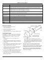
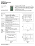
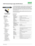
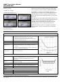
HOBO® Pro v2 User’s Manual
(Part # U23-00x)
Inside this package:
• HOBO® Pro v2 logger
• Clamp and mounting screws
Thank you for purchasing a HOBO data logger. With proper
care, it will give you years of accurate, reliable measurements.
The HOBO Pro v2 logger’s environmentally rugged case is
designed for years of reliable use in outdoor applications. It has
enough memory to record over 42,000 12-bit measurements.
The U23-001 and U23-002 models also feature user-replaceable
RH sensors.
The logger uses an optical USB communications interface (via a
compatible shuttle or base station) for launching and reading out
the logger. The optical interface allows the logger to be
offloaded without compromising the electronics. The USB
compatibility allows for easy setup and fast downloads.
HOBOware® software version 2.2.1 or higher is required for
logger operation. Visit www.onsetcomp.com for compatible
software.
Doc #10694-J, MAN-U23
Onset Computer Corporation
Specifications
Temperature Sensor
Operation range
Accuracy
Resolution
Response time
(typical to 90%)
Stability (drift)
Internal sensors: -40° to 70°C (-40° to 158°F)
U23-002 external temperature sensor: -40° to 70°C (-40° to 158°F)
U23-003 and U23-004 external sensors: -40° to 100°C
(-40° to 212°F), with tip and cable immersion in fresh water
up to 50°C (122°F) for one year
±0.21°C from 0° to 50°C (±0.38°F from 32° to 122°F); see Plot A
0.02°C at 25°C (0.04°F at 77°F); see Plot A
U23-001 Internal sensor: 40 minutes in air moving 1 m/sec
U23-002 external temperature sensor: 5 minutes in air moving
1 m/sec
U23-003 and U23-004 external sensors: 3 minutes in air moving
1 m/sec; 30 seconds in stirred water
< 0.1°C (0.18°F) per year
Plot A
Relative Humidity Sensor (U23-001, U23-002 only)
Operation range
Accuracy
Resolution
Response time
(typical to 90%)
Stability (drift)
0-100% RH, -40° to 70°C (-40° to 158°F)
Exposure to conditions below -20°C (-4°F) or above 95% RH may
temporarily increase the maximum RH sensor error by an
additional 1%
±2.5% from 10% to 90% RH (typical), to a maximum of ±3.5%.
See Plot B for full range.
0.03%
U23-001: 40 minute in air moving 1 m/sec with protective cap
U23-002: 5 minutes in air moving 1 m/sec with protective cap
< 1% per year typical; hysteresis 1%
Logger
Operation range
Real-time clock
Battery
-40° to 70°C (-40° to 158°F)
± 1 minute per month 0° to 50°C (32° to 122°F)
1/2 AA, 3.6 Volt lithium, user-replaceable (part # HP-B)
Plot B
© 2010–2012 Onset Computer Corporation. All rights reserved. Patent #: 6,826,664.
Onset, HOBO, and HOBOware are registered trademarks of Onset Computer Corporation. Other products and brand names may be trademarks or registered trademarks of their
respective owners.
HOBO Pro v2 User’s Manual
Battery life (typical use) 3 years with 1 minute or greater logging interval
Memory (non-volatile) 64K bytes memory (approx. 21,000 temperature and RH measurements)
Materials
All models: ASA styrene polymer housing and mounting clamp; polypropylene protective cap; Buna-N o-ring(s);
U23-001, U23-002 only: ASA styrene polymer RH sensor cap; modified hydrophobic polyethersulfone membrane
Cables
U23-001: No cables
U23-002: One 184 cm (6 ft.) PVC cable; sensor diameter 1 cm (0.38 in.)
U23-003: Two 184 cm (6 ft.) PVC cables; sensor diameter 0.5 cm (0.20 in.)
U23-004: One 184 cm (6 ft.) PVC cable; sensor diameter 0.5 cm (0.20 in.)
Electronics housing is NEMA 6P equivalent (tolerant of brief submergence);
Environmental rating
Units with RH sensors are NEMA 4 equivalent (splash-resistant)
Launch modes
Immediate start; delayed start
Logging interval
Fixed-rate or multiple logging intervals, with up to 8 user-defined logging intervals and durations; logging intervals from
1 second to 18 hours (refer to HOBOware software manual)
Offload modes
Offload while logging; stop and offload
Battery indication
Battery voltage can be viewed in status screen and optionally logged in datafile. Low battery indication in datafile.
Weight
Dimensions
U23-001: 57 g (1.5 oz); U23-002: 118 g (3.1 oz); U23-003: 138 g (3.7 oz); U23-004: 102 g (2.7 oz)
Housing measures 10.2 × 3.8 cm (4.0 × 1.5 in.)
NIST certificate
Temperature certificate available for additional charge
The CE Marking identifies this product as complying with the relevant directives in the European Union (EU).
Accessories available
• RH sensor replacement kit for U23-001
(Part # HUM-RHPCB-1)
• RH sensor replacement kit for U23-002
(Part # HUM-RHPCB-2)
• Replacement cable/sensor for U23-002 (CABLE-U23-002)
Connecting the logger
The HOBO Pro v2 requires a coupler (Part # COUPLER2-E)
and USB-Optic Base Station (Part # BASE-U-4) or HOBO
Waterproof Shuttle (Part # U-DTW-1) to connect to the
computer.
1. Install the logger software on your computer before
7. Use the logger software to launch the logger, check the
proceeding.
logger’s status, read it out, stop it manually with the software,
or let it continue to record data until the memory is full. Or,
use the HOBO Waterproof Shuttle to read out and relaunch
the logger in the field.
2. Follow the instructions that came with your base station or
shuttle to attach the base station or shuttle to a USB port on
the computer.
Refer to the software user’s guide for complete details on
launching, reading out, and viewing data from the logger.
3. Make sure the logger’s communications window is clean and
dry. (Use a clean, nonabrasive cloth, if necessary.) If the
logger is damp, wipe off excess moisture.
Important: USB communications may not function properly
at temperatures below 0°C (32°F) or above 50°C (122°F).
4. Attach the coupler to the base station or shuttle, then insert
the logger into the coupler with the ridge on the logger
aligned with the ridge on the coupler.
Note: The first time you launch the logger, the deployment
number will be greater than zero. Onset launches the loggers to
test them prior to shipping.
5. If you are using the HOBO Waterproof Shuttle, briefly press
the coupler lever to put the shuttle into base station mode.
6. If the logger has never been connected to the computer
before, it may take a few seconds for the new hardware to be
detected by the computer.
2
HOBO Pro v2 User’s Manual
Operation
Replacing the RH sensor
A light (LED) in the communications window of the logger
confirms logger operation. (In brightly lit areas, it may be
necessary to shade the logger to see the LED blink.) The
following table explains when the light blinks during logger
operation:
The RH sensor (on models U23-001 and U23-002) is protected
by an ASA styrene polymer cap and a modified hydrophobic
polyethersulfone fluid barrier membrane that allows vapor to
penetrate while protecting the sensor from condensation.
When:
The logger is logging
The logger is awaiting a
start because it was
launched in Start At
Interval or Delayed Start
mode
RH sensor performance may degrade over time. To replace the
RH sensor in your logger, refer to the diagram and instructions
for your logger:
The “OK” light:
Blinks once every one to four
seconds (the shorter the logging
interval, the faster the light blinks);
blinks when logging a sample
Blinks once every eight seconds
until logging begins
U23-001 RH Sensor Replacement Steps
1. Turn the RH sensor cap counter-clockwise slightly and pull
to remove it. Discard the sensor cap, membrane, and o-ring.
Clean the sensor end of the logger.
Face-on view with spacer installed
Logger
Sample and event logging
The logger can record two types of data: samples and events.
Samples are the sensor measurements recorded at each logging
interval (for example, temperature every minute). Events are
independent occurrences triggered by a logger activity, such as
Bad Battery or Host Connected. Events help you determine what
was happening while the logger was logging.
Spacer
Protective Membrane
RH Sensor Board
The logger stores 64K of data, and can record over 42,000 12-bit
measurements.
RH Sensor
WARNING: Do not touch
the actual sensor (black
chip). Doing so may
compromise accuracy.
Deploying and protecting the logger
• To clean the logger’s case, use a sponge with warm, soapy
water.
O-ring
RH Sensor Cap
2. There may be a spacer installed on the RH Sensor Board.
Remove and discard the spacer.
• Use the included clamp to mount the
logger to a surface. The clamp has two
holes for the screws, 44 mm (1.7 inches)
apart.
3. Note the orientation of the small circuit board containing the
RH sensor. With a pair of needle-nose pliers, grip the sensor
board pins. Pull out and discard the board.
The clamp is slightly tapered to
accommodate the logger. Install the
clamp so the logger fits better with its
communication window facing up. This
will prevent condensation from pooling
around the sensor and/or grommet.
4. Use needle-nose pliers to hold the pins on the new sensor
board, push the board gently but firmly and install it in the
same orientation as the old board. Make sure it engages with
the pins inside the logger housing. Do not touch the sensor
itself; only touch the sides of the board.
5. Install the new spacer on the sensor board by placing the
spacer onto the third pin from the left (use the topmost hole
on the spacer instead of the center hole).
• A solar shield is recommended if the
logger will be exposed to sunshine.
• Periodically inspect the three desiccant packs located in the
logger cap. If they are not bright blue, dry them following the
instructions below.
6. Make sure the o-ring is clean and seated properly, and set the
protective membrane on top (either side can face up).
7. Put the sensor cap back on. Push down and turn it slightly
clockwise to close it securely. Do not force it. If the cap does
not go on easily, the sensor may be installed incorrectly.
Check the sensor orientation and try again.
To dry a desiccant pack, remove it from the logger cap and
leave in a warm (≤70oC (158oF), dry location until the bright
blue color is restored. (Refer to the “Battery” section for
instructions on removing and replacing the logger cap.).
8. Check logger status in HOBOware to verify the RH reading.
If a desiccant pack remains pink and will not turn blue, replace
it with a new desiccant pack (Onset Part #: DESICCANT1)
3
HOBO Pro v2 User’s Manual
2. Carefully pull out the circuit board containing the battery. (If
the logger has an external sensor, you will probably find it
easier to push the cable(s) into the case to push the circuit
board out.)
U23-002 RH Sensor Replacement Steps
Grasp the cap and membrane and pull firmly. Discard them.
1. Note the orientation of the small circuit board containing the
RH sensor. Pull it out and discard it.
3. Examine the desiccant packs that were packed into the case.
If the desiccant is not bright blue, put the desiccant packs in a
warm, dry place until the blue color is restored.
Cable from logger
Receptacle
RH sensor
Protective cap
Cable from sensor
(if applicable)
Circuit board
RH sensor cap
& protective membrane
Grommet for cable
(if applicable)
Battery
Desiccant packs
2. Holding the sides of the board only, push gently but firmly to
install the new sensor (Onset part # HUM-RHPCB-2) in the
same orientation. WARNING: Do not touch the actual
sensor (black chip) itself; doing so may compromise
accuracy.
4. Install a new 1/2 AA, 3.6 Volt lithium battery (part # HP-B).
The negative end of the battery must face towards the
communication LEDs.
3. Put the new sensor cap and membrane on. Do not force the
cap. If it does not go on easily, the sensor may be installed
backwards. Reverse the sensor and try again.
5. Use a clean, dry cloth to wipe away any moisture inside the
case.
6. Push the board and the desiccant packs back into the case,
taking care not to bend the communication LEDs. Align the
board with the grooves inside the case. (If you try to put the
board in upside-down, the battery will get in the way.)
Battery
Typical battery life is about three years. Actual battery life is a
function of the number of deployments, logging interval, and
operation/storage temperature of the logger. To obtain a threeyear battery life, use a logging interval of one minute or greater,
and operate and store the logger at temperatures between 0° and
40°C (32° and 104°F).
7. Make sure o-ring on the protective cap is still in place. It
should not be pinched, twisted, or trapping dirt or lint, which
could interfere with the protective cap.
8. Line up the bumps on the protective cap with the notches in
the logger’s case. Push and turn the cap slightly clockwise.
Pull the slack in the sensor cable(s) if applicable. Handtighten the grommet and then turn an additional half turn
with a wrench (do not force).
Frequent deployments with logging intervals of less than one
minute, and continuous storage/operation at temperatures above
40°C, will result in significantly lower battery life. For example,
continuous logging at a one-second logging interval will result in
a battery life of approximately one month.
WARNING: Do not cut open, incinerate, heat above
100°C (212°F), or recharge the lithium battery. The battery
may explode if the logger is exposed to extreme heat or
conditions that could damage or destroy the battery case. Do
not dispose of the logger or battery in fire. Do not expose the
contents of the battery to water. Dispose of the battery
according to local regulations for lithium batteries.
The logger can report and log its own battery voltage. If the
battery falls below 3.1 V, the logger will record a “bad battery”
event in the datafile. If the datafile contains “bad battery” events,
or if logged battery voltage repeatedly falls below 3.3 V, the
battery is failing and should be replaced before the next
deployment. To change the battery:
1. Turn slightly counter-clockwise and pull to remove the
protective cap. Loosen the cable grommet on the opposite
end, if the logger has an external sensor.
4