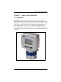
1
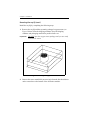
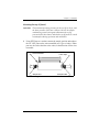
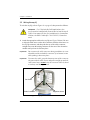
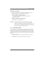
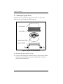
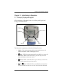
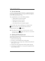
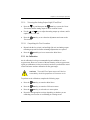
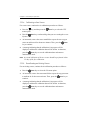
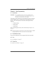
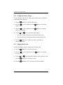
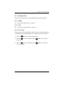
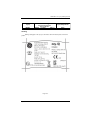
GE
Measurement & Control
Oxygen Analysis
oxy.IQ
Panametrics Oxygen Transmitter
User’s Manual
910-296 Rev. B
March 2015
GE
Measurement & Control
oxy.IQ
Panametrics Oxygen Transmitter
User’s Manual
910-296 Rev. B
March 2015
www.ge-mcs.com
©2015 General Electric Company. All rights reserved.
Technical content subject to change without notice.
[no content intended for this page]
ii
Preface
Information Paragraphs
Note: These paragraphs provide additional information about the topic
which is helpful but is not essential to proper completion of the task.
Important:
These paragraphs provide emphasis to instructions that are
essential to proper setup of the equipment. Failure to follow
these instructions carefully may cause unreliable performance.
Indicates a potentially hazardous situation
which can result in serious personal injury or death, if it is
not avoided.
WARNING!
Indicates a potentially hazardous situation
which can result in minor or moderate injury to personnel
or damage to the equipment, if it is not avoided.
CAUTION!
Safety Issues
It is the responsibility of the user to make sure
all local, county, state and national codes, regulations, rules
and laws related to safety and safe operating conditions
are met for each installation.
WARNING!
oxy.IQ User’s Manual
iii
Preface
Auxiliary Equipment
Local Safety Standards
The user must make sure that he operates all auxiliary equipment in
accordance with local codes, standards, regulations, or laws applicable to
safety.
Working Area
Auxiliary equipment may have both manual
and automatic modes of operation. As equipment can
move suddenly and without warning, do not enter the work
cell of this equipment during automatic operation, and do
not enter the work envelope of this equipment during
manual operation. If you do, serious injury can result.
WARNING!
Make sure that power to the auxiliary
equipment is turned OFF and locked out before you
perform maintenance procedures on the equipment.
WARNING!
Qualification of Personnel
Make sure that all personnel have manufacturer-approved training
applicable to the auxiliary equipment.
Personal Safety Equipment
Make sure that operators and maintenance personnel have all safety
equipment applicable to the auxiliary equipment. Examples include safety
glasses, protective headgear, safety shoes, etc.
Unauthorized Operation
Make sure that unauthorized personnel cannot gain access to the operation
of the equipment.
iv
oxy.IQ User’s Manual
Preface
Environmental Compliance
Waste Electrical and Electronic Equipment (WEEE) Directive
GE Measurement & Control Solutions is an active participant in Europe’s
Waste Electrical and Electronic Equipment (WEEE) take-back initiative,
directive 2012/19/EU.
The equipment that you bought has required the extraction and use of
natural resources for its production. It may contain hazardous substances
that could impact health and the environment.
In order to avoid the dissemination of those substances in our environment
and to diminish the pressure on the natural resources, we encourage you to
use the appropriate take-back systems. Those systems will reuse or recycle
most of the materials of your end life equipment in a sound way.
The crossed-out wheeled bin symbol invites you to use those systems.
If you need more information on the collection, reuse and recycling
systems, please contact your local or regional waste administration.
Visit http://www.ge-mcs.com/en/about-us/environmental-health-andsafety/1741-weee-req.html for take-back instructions and more
information about this initiative.
oxy.IQ User’s Manual
v
Preface
[no content intended for this page]
vi
oxy.IQ User’s Manual
Contents
Chapter 1. Features and Capabilities
1.1 Introduction . . . . . . . . . . . . . . . . . . . . . . . . . . . . . . . . . . . . . . . . . . . . . . . . . . . . . . . . . .1
1.2 Hazardous Location Certifications . . . . . . . . . . . . . . . . . . . . . . . . . . . . . . . . . . . . .2
1.3 Applications . . . . . . . . . . . . . . . . . . . . . . . . . . . . . . . . . . . . . . . . . . . . . . . . . . . . . . . . . .2
1.4 Features. . . . . . . . . . . . . . . . . . . . . . . . . . . . . . . . . . . . . . . . . . . . . . . . . . . . . . . . . . . . . .3
1.5 Sample Systems . . . . . . . . . . . . . . . . . . . . . . . . . . . . . . . . . . . . . . . . . . . . . . . . . . . . . .4
Chapter 2. Installation
2.1 Mounting the oxy.IQ. . . . . . . . . . . . . . . . . . . . . . . . . . . . . . . . . . . . . . . . . . . . . . . . . . .5
2.2 Wiring the oxy.IQ. . . . . . . . . . . . . . . . . . . . . . . . . . . . . . . . . . . . . . . . . . . . . . . . . . . . . .8
2.2.1
Longer Cable Lengths. . . . . . . . . . . . . . . . . . . . . . . . . . . . . . . . . . . . . . . . .9
2.3 Installing an Oxygen Sensor . . . . . . . . . . . . . . . . . . . . . . . . . . . . . . . . . . . . . . . . . 10
Chapter 3. Initial Setup & Operation
3.1 The oxy.IQ Display and Keypad . . . . . . . . . . . . . . . . . . . . . . . . . . . . . . . . . . . . . .
3.2 The oxy.IQ Menu Map . . . . . . . . . . . . . . . . . . . . . . . . . . . . . . . . . . . . . . . . . . . . . . .
3.3 Adjusting and Calibrating the oxy.IQ . . . . . . . . . . . . . . . . . . . . . . . . . . . . . . . . .
3.3.1
Selecting the Output Range . . . . . . . . . . . . . . . . . . . . . . . . . . . . . . . . .
3.3.2
Trimming the Analog Output . . . . . . . . . . . . . . . . . . . . . . . . . . . . . . . .
3.3.3
Air Calibration . . . . . . . . . . . . . . . . . . . . . . . . . . . . . . . . . . . . . . . . . . . . . .
3.3.4
Span Gas Calibration . . . . . . . . . . . . . . . . . . . . . . . . . . . . . . . . . . . . . . .
13
14
14
15
16
17
19
Chapter 4. User Programming
4.1 Introduction . . . . . . . . . . . . . . . . . . . . . . . . . . . . . . . . . . . . . . . . . . . . . . . . . . . . . . . .
4.2 The Calibration Menu . . . . . . . . . . . . . . . . . . . . . . . . . . . . . . . . . . . . . . . . . . . . . . .
4.2.1
Air . . . . . . . . . . . . . . . . . . . . . . . . . . . . . . . . . . . . . . . . . . . . . . . . . . . . . . . . .
4.2.2
Span Gas. . . . . . . . . . . . . . . . . . . . . . . . . . . . . . . . . . . . . . . . . . . . . . . . . . .
4.2.3
Sensor Life . . . . . . . . . . . . . . . . . . . . . . . . . . . . . . . . . . . . . . . . . . . . . . . . .
4.3 The Display Menu . . . . . . . . . . . . . . . . . . . . . . . . . . . . . . . . . . . . . . . . . . . . . . . . . . .
4.3.1
Select the O2 Parameter . . . . . . . . . . . . . . . . . . . . . . . . . . . . . . . . . . . .
4.3.2
Display the Sensor Range . . . . . . . . . . . . . . . . . . . . . . . . . . . . . . . . . . .
4.3.3
Adjust the Contrast . . . . . . . . . . . . . . . . . . . . . . . . . . . . . . . . . . . . . . . . .
4.4 The Output Menu . . . . . . . . . . . . . . . . . . . . . . . . . . . . . . . . . . . . . . . . . . . . . . . . . . .
4.4.1
Range. . . . . . . . . . . . . . . . . . . . . . . . . . . . . . . . . . . . . . . . . . . . . . . . . . . . . .
4.4.2
Trim. . . . . . . . . . . . . . . . . . . . . . . . . . . . . . . . . . . . . . . . . . . . . . . . . . . . . . . .
4.4.3
Error Type . . . . . . . . . . . . . . . . . . . . . . . . . . . . . . . . . . . . . . . . . . . . . . . . . .
4.4.4
Error Output . . . . . . . . . . . . . . . . . . . . . . . . . . . . . . . . . . . . . . . . . . . . . . . .
21
21
21
21
22
23
23
24
24
25
25
25
25
27
oxy.IQ User’s Manual
vii
Contents
Chapter 5. The Service Menu
5.1 Menu Map & Service Passcode. . . . . . . . . . . . . . . . . . . . . . . . . . . . . . . . . . . . . . . 29
5.2 Entering the Service Menu . . . . . . . . . . . . . . . . . . . . . . . . . . . . . . . . . . . . . . . . . . . 29
5.2.1
Diagnostics. . . . . . . . . . . . . . . . . . . . . . . . . . . . . . . . . . . . . . . . . . . . . . . . . 30
Chapter 6. Specifications
6.1 Intrinsically Safe (IS) Installation . . . . . . . . . . . . . . . . . . . . . . . . . . . . . . . . . . . . . .
6.1.1
Power Requirements . . . . . . . . . . . . . . . . . . . . . . . . . . . . . . . . . . . . . . . .
6.1.2
Cable . . . . . . . . . . . . . . . . . . . . . . . . . . . . . . . . . . . . . . . . . . . . . . . . . . . . . .
6.1.3
Output . . . . . . . . . . . . . . . . . . . . . . . . . . . . . . . . . . . . . . . . . . . . . . . . . . . . .
6.2 Non-Incendive (Div 2) and General Purpose Installation . . . . . . . . . . . . . . .
6.2.1
Cable . . . . . . . . . . . . . . . . . . . . . . . . . . . . . . . . . . . . . . . . . . . . . . . . . . . . . .
6.2.2
Power Requirements . . . . . . . . . . . . . . . . . . . . . . . . . . . . . . . . . . . . . . . .
6.3 All Installations. . . . . . . . . . . . . . . . . . . . . . . . . . . . . . . . . . . . . . . . . . . . . . . . . . . . . .
6.3.1
Process Wetted Materials . . . . . . . . . . . . . . . . . . . . . . . . . . . . . . . . . . .
6.3.2
User-Selectable Measurement Ranges. . . . . . . . . . . . . . . . . . . . . . .
6.3.3
Accuracy . . . . . . . . . . . . . . . . . . . . . . . . . . . . . . . . . . . . . . . . . . . . . . . . . . .
6.3.4
Repeatability . . . . . . . . . . . . . . . . . . . . . . . . . . . . . . . . . . . . . . . . . . . . . . .
6.3.5
Resolution . . . . . . . . . . . . . . . . . . . . . . . . . . . . . . . . . . . . . . . . . . . . . . . . . .
6.3.6
Linearity. . . . . . . . . . . . . . . . . . . . . . . . . . . . . . . . . . . . . . . . . . . . . . . . . . . .
6.3.7
O2 Sensor Operating Temperature . . . . . . . . . . . . . . . . . . . . . . . . . .
6.3.8
Sample Pressure. . . . . . . . . . . . . . . . . . . . . . . . . . . . . . . . . . . . . . . . . . . .
6.3.9
Atmospheric Pressure Effect. . . . . . . . . . . . . . . . . . . . . . . . . . . . . . . . .
6.3.10 Process Connection. . . . . . . . . . . . . . . . . . . . . . . . . . . . . . . . . . . . . . . . .
6.3.11 Dimensions. . . . . . . . . . . . . . . . . . . . . . . . . . . . . . . . . . . . . . . . . . . . . . . . .
6.3.12 Weight . . . . . . . . . . . . . . . . . . . . . . . . . . . . . . . . . . . . . . . . . . . . . . . . . . . . .
6.3.13 Sample Flow Rate . . . . . . . . . . . . . . . . . . . . . . . . . . . . . . . . . . . . . . . . . .
6.3.14 Electrical Classification. . . . . . . . . . . . . . . . . . . . . . . . . . . . . . . . . . . . . .
6.3.15 European Compliance . . . . . . . . . . . . . . . . . . . . . . . . . . . . . . . . . . . . . .
6.3.16 Product Label. . . . . . . . . . . . . . . . . . . . . . . . . . . . . . . . . . . . . . . . . . . . . . .
viii
31
31
31
31
31
31
31
32
32
32
32
33
33
33
33
33
33
33
33
33
33
34
34
35
oxy.IQ User’s Manual
Contents
Appendix A. Outline and Installation Drawings . . . . . . . . . . . . . . . . . . . . . . . . . 37
Appendix B. Menu Maps . . . . . . . . . . . . . . . . . . . . . . . . . . . . . . . . . . . . . . . . . . . . . . 45
Appendix C. Order String . . . . . . . . . . . . . . . . . . . . . . . . . . . . . . . . . . . . . . . . . . . . . 49
Appendix D. Certifications . . . . . . . . . . . . . . . . . . . . . . . . . . . . . . . . . . . . . . . . . . . . 51
D.1
D.2
D.3
D.4
D.5
ATEX EC-Type Examination Certificate . . . . . . . . . . . . . . . . . . . . . . . . . . . . . . .
ATEX IECEx MAM Ex Certificate. . . . . . . . . . . . . . . . . . . . . . . . . . . . . . . . . . . . . . .
Canadian Certificate of Compliance . . . . . . . . . . . . . . . . . . . . . . . . . . . . . . . . .
FM Certificate of Compliance . . . . . . . . . . . . . . . . . . . . . . . . . . . . . . . . . . . . . . . .
IECEx Certificate of Conformity . . . . . . . . . . . . . . . . . . . . . . . . . . . . . . . . . . . . . .
52
56
58
60
62
Addendum A. oxy.IQ Safety Manual. . . . . . . . . . . . . . . . . . . . . . . . . . . . . . . . . . . . 71
Addendum B. Declaration of Conformity . . . . . . . . . . . . . . . . . . . . . . . . . . . . . . . 77
oxy.IQ User’s Manual
ix
Contents
[no content intended for this page]
x
oxy.IQ User’s Manual
Chapter 1. Features and Capabilities
Chapter 1. Features and Capabilities
1.1 Introduction
The oxy.IQ Panametrics Oxygen Transmitter (see Figure 1 below) is a
highly reliable and cost-effective two-wire, loop-powered transmitter with a
linearized 4 to 20 mA output. It measures oxygen content in ten ppm ranges
(10, 20, 50, 100, 200, 500, 1000, 2000, 5000 and 10000 ppm) and eight
percentage ranges (1, 2, 5, 10, 21, 25, 50 and 100%). All ranges are
user-selectable. This compact transmitter uses proven sensor technology to
accurately measure O2 in a variety of gases, even in hazardous (classified)
locations.
Figure 1: oxy.IQ
oxy.IQ User’s Manual
1
Chapter 1. Features and Capabilities
1.2 Hazardous Location Certifications
When equipped with an optional zener barrier or galvanic isolator, the
oxy.IQ can be mounted in a hazardous (classified) location. The oxy.IQ
with Intrinsically Safe option is certified to USA, Canadian, ATEX, and
international IECEx IS requirements. The standard oxy.IQ is certified to
USA, Canadian, EU ATEX and International IECEx Div2/Zone 2 Non
Incendive requirements.
1.3 Applications
Some typical applications for the oxy.IQ Panametrics oxygen transmitter
include the following:
2
•
Glove box purge and leak detection
•
Natural gas
•
Semiconductor wafer machines
•
Coating process machines
•
Membrane air separators
•
Inert welding gases
•
Pure gaseous hydrocarbon streams
•
Process monitoring of gaseous monomers
•
Heat treating and bright annealing
oxy.IQ User’s Manual
Chapter 1. Features and Capabilities
1.4 Features
The oxy.IQ oxygen sensor is an advanced galvanic fuel cell that provides
superior performance, accuracy, stability and long life. The cell’s innovative
design eliminates the potential for negative signal output and reduces
sources of contamination.
The cell is unaffected by other background gases or hydrocarbons and is
compatible with acidic gases (OX-2 and OX-4 cells). Recovery from air at
low ppm levels takes just a few minutes. Because the cell is self-contained,
minimal maintenance is required. There is no electrolyte to change and no
electrodes to clean.
The oxy.IQ offers the following features:
•
Two-wire, loop-powered, 4 to 20 mA transmitter
•
Display with keypad
•
Intrinsically-safe option
•
Proven galvanic fuel cell O2 sensor technology
•
User-selectable ranges for ppm and percent oxygen
•
User-friendly and intuitive user interface with diagnostics
•
Microprocessor-based, all-digital technology for reliable operation
•
Low maintenance, economical and compact
•
Sensor failure output error
•
Sensor lifetime indication
•
NAMUR error indication
oxy.IQ User’s Manual
3
Chapter 1. Features and Capabilities
1.5 Sample Systems
In addition to the standard features and options, GE offers a full line of
sample handling systems for a variety of applications. If needed, GE can
design and build a sample conditioning system to meet unique application
requirements. Please contact GE for details.
Table 1 below lists some background gases that can interfere with the
oxygen sensor.
Table 1: Oxygen Sensor Interference Gases
OX-1 & 5 ppm
OX-2 ppm
Gas
Cont.
Cont.
OX-3 %
H2S
<5 ppm
<10 ppm
SO3
<10 ppm
<10 ppm
0.01 %
SO2
<10 ppm
(3)
HCl
<1000 ppm
HCN
Cont.
OX-4 %
Int. (1)
Cont.
Int.
0.001 %
0.1 %
0.1 %
0.01 %
0.1 %
0.01 %
0.1 %
(3)
(3)
(3)
0.1 %
1.0 %
(3)
(3)
<1000 ppm
(3)
0.1 %
1.0 %
(3)
(3)
CO2
<1000 ppm
(3)
0.1 %
20 &
(3)
(3)
NO2
(2)
(2)
(2)
(2)
(2)
(2)
Cl2
(2)
(2)
(2)
(2)
(2)
(2)
0.0005 % 0.01 %
Cont. = Continuous, Int. = Intermittent
(1) Recommended maximum exposure 30 minutes, followed by flushing with
ambient air for an equal period.
(2) Minimal effect on sensor performance, but produces signal interference of
1:2 ratio for ppm levels only (e.g., 100 ppm NO2 looks like 200 ppm O2).
(3) Minimal effect on sensor performance
4
oxy.IQ User’s Manual
Chapter 2. Installation
Chapter 2. Installation
2.1 Mounting the oxy.IQ
To install the oxy.IQ into the process or sample system, refer to Figure 9 on
page 38 or Figure 2 below and proceed to the next page.
Figure 2: Outline and Installation Drawing
Note: To avoid collecting condensate that may damage the oxygen sensor,
mount the oxy.IQ in an upright position, with the sensor manifold
below the electronics module.
oxy.IQ User’s Manual
5
Chapter 2. Installation
Mounting the oxy.IQ (cont.)
Install the oxy.IQ by completing the following steps:
1. Remove the oxy.IQ and the separately-packaged oxygen sensor (see
Figure 3 below) from the shipping container. Keep the shipping
container and packaging material for possible future use.
Important:
DO NOT open the oxygen sensor package until you are ready
to install the sensor.
Figure 3: Packaged Oxygen Sensor
2. Remove the sensor manifold by unscrewing it from the blue knurled nut
on the sensor base at the bottom of the electronics module.
6
oxy.IQ User’s Manual
Chapter 2. Installation
Mounting the oxy.IQ (cont.)
Important:
The maximum operating pressure for the oxy.IQ is 10 psi, and
the burst pressure of the unit is 200 psi. Be sure the sample
conditioning system is designed to maintain the oxy.IQ
pressure below these limits, and that the oxy.IQ outlet is vented
to atmosphere during operation and calibration.
3. Using PTFE tape as a sealant, connect the sample gas inlet and outlet to
the 1/8” NPT ports on the sensor manifold (see Figure 4 below). Either
port may be used as the inlet or the outlet, as the direction of flow does
not matter.
Sensor Manifold
PTFE Tape
Sample Inlet
Sample Outlet
Figure 4: Sensor Manifold Installation
oxy.IQ User’s Manual
7
Chapter 2. Installation
2.2 Wiring the oxy.IQ
To wire the oxy.IQ, refer to Figure 14 on page 43, then proceed as follows:
For IS (Intrinsically Safe) applications, the
oxy.IQ must be installed with a zener barrier (see the top of
Figure 14 on page 43). Also, for installations in a hazardous
location, the blue IS cable (p/n 704-1318-02, 10) must be
used.
WARNING!
1. Attach the appropriate cable to the oxy.IQ (see Figure 5 below). Be sure
to align the white arrow on the cable connector with the white arrow on
the oxy.IQ connector, and then push the top of the cable connector
straight down onto the mating connector on the rear of the electronics
module until you hear it click into place.
Important:
Do not rotate the cable connector during installation (it is not
threaded) and do not hold the connector by its bottom section
while pushing it down into place.
Important:
To remove the cable, grasp the bottom section of the connector
(the part with the white arrow) and pull it straight up until the
cable comes loose. DO NOT twist the connector either by hand
or with any tool during removal.
Std. Cable
Cable Connector
Alignment Arrow
Figure 5: oxy.IQ Cable and Connector
8
oxy.IQ User’s Manual
Chapter 2. Installation
Wiring the oxy.IQ (cont.)
2. Connect the flying lead end of the cable as shown in the wiring
diagram, according to one of the following conditions:
•
•
No Zener Barrier or Galvanic Isolator:
For use in non-hazardous areas or Div 2 hazardous areas
(certification pending).
With Zener Barrier or Galvanic Isolator:
Required for use in hazardous areas.
Important:
To remove the cable from the oxy.IQ electronics module,
simply pull straight up on the lower section of the cable
connector as close to the oxy.IQ body as possible. Do not pull
on the cable or the upper portion of the cable connector, and
do not try to unscrew the cable connector.
2.2.1 Longer Cable Lengths
GE offers cables in 2 m and 10 m standard lengths. Longer cable lengths
may be used with the oxy.IQ, but these are not available from GE. If you
require a longer cable, refer to the following figures for the required cable
specifications and construct your own cable for splicing onto the standard
GE cable:
•
Standard Cable: Figure 10 on page 39 and Figure 11 on page 40
•
IS Cable: Figure 12 on page 41 and Figure 13 on page 42
oxy.IQ User’s Manual
9
Chapter 2. Installation
2.3 Installing an Oxygen Sensor
To install a new or replacement oxygen sensor in the oxy.IQ, refer to
Figure 6 below and complete the following steps:
Sensor Base
Knurled Nut
Oxygen Sensor Ring
Sensor Manifold
Figure 6: Oxygen Sensor Installation
1. Disconnect the power from the oxy.IQ.
2. Loosen the blue knurled nut and remove the oxy.IQ electronics module
from the sensor manifold. If a previous oxygen sensor is already in
place, remove and discard it.
10
oxy.IQ User’s Manual
Chapter 2. Installation
Installing an Oxygen Sensor (cont.)
3. Apply power to the unit. The screen will display “INITIALIZING PLEASE
WAIT” for a few seconds before it begins to display measurement data.
Note: Before continuing with the installation, become familiar with the
procedures for programming and calibrating the oxy.IQ discussed in
Chapter 3, Initial Setup & Operation.
4. Trim the 4-20 mA analog output and set the range to 0-25% oxygen.
5. Open the airtight package (see Figure 3 on page 6) and remove the
oxygen sensor from the package. To maintain the oxygen sensor’s
energy level, remove the red grounding tab and immediately install the
sensor in the oxy.IQ
6. Orient the sensor so that its gold-plated electrodes are facing the
spring-loaded contact pins in the sensor base (see Figure 6 on page 10).
Firmly press the oxygen sensor into the sensor base at the bottom of the
oxy.IQ electronics module.
7. Perform an air calibration on the new oxygen sensor at this time. On the
0-25% oxygen scale, a properly calibrated oxygen sensor shows a
reading of 20.9% on the display and generates a current of 17.4 mA at
the 4-20 mA analog output terminals.
8. Using the blue knurled nut, attach the oxy.IQ electronics module with
the calibrated oxygen sensor to the sensor manifold. Rotate the display
as desired and then hand-tighten the blue knurled nut.
Important:
Make sure that the O-ring on the top of the sensor manifold is
in place and undamaged. If necessary, contact GE for a
replacement.
oxy.IQ User’s Manual
11
Chapter 2. Installation
Installing an Oxygen Sensor (cont.)
9. Begin the flow of the process gas. The analog output reading will drop
as the oxygen sensor adjusts to the reduced oxygen level. During this
time, reset the range as required.
10. For improved accuracy in the ppm oxygen ranges, a span gas calibration
should now be performed (see “Span Gas Calibration” on page 19).
Important:
12
Sensor life is dependent on the application. High oxygen
concentrations and contaminants such as acidic gases will
shorten the sensor life.
oxy.IQ User’s Manual
Chapter 3. Initial Setup & Operation
Chapter 3. Initial Setup & Operation
3.1 The oxy.IQ Display and Keypad
All programming of the oxy.IQ is done via the front panel keypad and
display, as illustrated below.
Display
Down Arrow
Up Arrow
Cancel
Enter
Figure 7: oxy.IQ Display and Keypad
The front panel components perform the following functions:
•
Display - Data measurements and the programming menus and
options are shown on the LCD display screen.
•
Enter - While in measurement mode, press this key to enter the
Main Menu. While in the Main Menu, press this key to save an
entry and advance to the next screen.
•
Cancel - While in the Main Menu, press this key to cancel an
entry and to return to the previous screen.
•
and
Keys - In the Main Menu, use these keys to move the
cursor between rows one row at a time in the direction indicated.
oxy.IQ User’s Manual
13
Chapter 3. Initial Setup & Operation
3.2 The oxy.IQ Menu Map
As an aid in navigating through the Main Menu, a complete Menu Map of
the user program is shown in Figure 15 on page 46. Refer to this figure as
needed while programming the oxy.IQ.
The oxy.IQ Main Menu consists of the following submenus:
•
Calibration Menu (no passcode required)
•
Display Menu (no passcode required)
•
Output Menu (no passcode required)
•
Service Menu (factory service passcode required)
To enter the Main Menu from normal display mode, simply press the
Enter key at any time. To leave the Main Menu and return to
measurement mode, press the
Cancel key.
Note: Depending on how deep you are in the menu structure, it may be
Cancel key more than once to return all the
necessary to press the
way back to measurement mode.
3.3 Adjusting and Calibrating the oxy.IQ
Upon startup, the following five-step adjustment and calibration procedure
must be performed on the oxy.IQ:
1.
Select the desired output range.
2.
Trim the low (4 mA) and high (20 mA) analog outputs.
3.
Upon installation of a new oxygen sensor, calibrate the unit with air for
either a ppm or % sensor.
4.
For ppm sensors only, purge the sensor with a low ppm oxygen gas.
5.
For all subsequent calibrations, use a span gas that is appropriate for the
sensor and range selected.
14
oxy.IQ User’s Manual
Chapter 3. Initial Setup & Operation
3.3.1 Selecting the Output Range
To select the desired measurement range, complete the following steps:
1.
Press the
Enter key to enter the Main Menu.
2.
Press the
key twice and then press the
Output menu.
3.
Press the
4.
Use the
and
keys to scroll through the available options, as
listed in Table 2 below.
Enter key to select the Range menu option.
Table 2: Available Output Ranges
Span Value
Units
% O2
ppm O2
5.
Enter key to enter the
1, 2, 5, 10, 21, 25, 50, 100
10, 20, 50, 100, 200, 500, 1000, 2000, 5000, 10000
After selecting the desired output range, press the
the selection. Then, press the
menu.
oxy.IQ User’s Manual
Enter key to save
Cancel key to return to the Output
15
Chapter 3. Initial Setup & Operation
3.3.2 Trimming the Analog Output
To trim the analog output, calibrate the low (4 mA) end of the output then
the high (20 mA) end of the output.
IMPORTANT:
3.3.2a
The 4 mA and 20 mA adjustments interact with each other.
Therefore, recheck the trim after the procedure has been
completed.
Preparing to Trim the Analog Output
Prepare to trim the analog output as follows:
1.
Connect an ammeter in series with the positive oxy.IQ power supply
lead, to monitor the analog output current.
2.
Press the
3.
Press the
key twice and then press the
Output menu.
4.
Press the
menu.
3.3.2b
Enter key to enter the Main Menu.
key and then press the
Enter key to enter the
Enter key to enter the Trim
Trimming the Analog Output Low (4 mA) End
1.
Press the
Enter key to enter the 4 mA Trim menu, and the analog
output is driven to about 4 mA.
2.
Use the
and
keys to adjust the analog output up or down, until it
equals 4.00 ± 0.01 mA.
3.
Press the
Enter key to save the trim adjustment and return to the
Trim menu.
16
oxy.IQ User’s Manual
Chapter 3. Initial Setup & Operation
3.3.2c
Trimming the Analog Output High (20 mA) End
1.
Press the
key and then press the
Enter key to enter the 20 mA
Trim menu, and the analog output is driven to about 20 mA.
2.
Use the
and
keys to adjust the analog output up or down, until it
equals 20.00 ± 0.01 mA.
3.
Press the
Enter key to save the trim adjustment and return to the
Trim menu.
3.3.2d
Completing the Trim Procedure
1.
Repeat both the low (4 mA) end and high (20 mA) end analog output
trimming steps until no further trimming adjustments are required.
2.
Press the
Cancel key twice to return to the Main Menu.
3.3.3 Air Calibration
An air calibration is always recommended upon installation of a new
oxygen sensor. However, because of the non-linearity of the oxygen sensor,
a span gas calibration (see the next section) can also be performed to ensure
a faster and more accurate calibration for the ppm ranges.
The useful life of ppm sensors will also be
extended by minimizing exposure of the sensor to air.
CAUTION!
To perform an air calibration, complete the following steps:
1.
Press the
Enter key to enter the Main Menu.
2.
Press the
Enter key to enter the Calibration menu.
3.
Press the
Enter key to select the Air menu option.
4.
Proceed to the appropriate section, depending on whether you are
calibrating a new sensor or recalibrating an existing sensor.
oxy.IQ User’s Manual
17
Chapter 3. Initial Setup & Operation
3.3.3a
Calibrating a New Sensor
For a new sensor, continue the air calibration procedure as follows:
1.
Press the
key and then press the
menu option.
Enter key to select the YES
2.
Press the
Enter key to acknowledge that you are resetting the sensor
lifetime clock.
3.
As instructed, remove the sensor manifold to expose the new oxygen
sensor to ambient air for about two minutes. Then, press the
key to continue.
4.
Enter
A message indicating that the calibration is in progress will be
displayed, and then the calibration data will be shown. At that time,
Enter key to save the calibration data and return to
press the
measurement mode.
Note: A second calibration of the new sensor should be performed within
1-2 days of the first calibration.
3.3.3b
Recalibrating an Existing Sensor
For an existing sensor, continue the air calibration procedure as follows:
1.
Press the
Enter key to select the NO menu option.
2.
As instructed, remove the sensor manifold to expose the oxygen sensor
to ambient air for about two minutes. Then, press the
continue.
3.
Enter key to
A message indicating that the calibration is in progress will be
displayed, and then the calibration data will be shown. At that time,
Enter key to save the calibration data and return to
press the
measurement mode.
18
oxy.IQ User’s Manual
Chapter 3. Initial Setup & Operation
3.3.4 Span Gas Calibration
Before beginning the span gas calibration, make sure the oxy.IQ is
indicating an O2 level less than the span gas value, to ensure an accurate
calibration. Then, start the flow of the span gas to the sensor. For accurate
calibration, the span gas should have an oxygen content of 70-90% of the
range being calibrated.
To perform the span calibration, complete the following steps:
1.
Use the equation below to calculate the expected mA output that
corresponds to the known oxygen content of the span gas:
Span Gas ppm
4.0 + 16.0 × -------------------------------------- = mA Output
Full Range ppm
For example, if the span gas contains 80 ppm oxygen and the
0-100 ppm range is being calibrated, the analog output should equal
4 + 16 x (80/100) = 16.8 mA.
2.
If you have not done so already, start the flow of span gas to the sensor
and allow both the 4-20 mA output reading and the display reading to
stabilize.
3.
After the reading has stabilized, press the
Main Menu.
4.
Press the
5.
Press the
key and then press the
Gas menu option.
6.
Press the
and
keys until the measurement agrees with the span
calibration gas value.
7.
Confirm that the reading on the display has stabilized, and press the
Enter key to enter the
Enter key to enter the Calibration menu.
Enter key to select the Span
Enter key to save the calibration. Then, press the
twice to return to measurement mode.
oxy.IQ User’s Manual
Cancel key
19
Chapter 3. Initial Setup & Operation
[no content intended for this page]
20
oxy.IQ User’s Manual
Chapter 4. User Programming
Chapter 4. User Programming
4.1 Introduction
IMPORTANT:
The oxy.IQ Service menu is for use by qualified service
personnel only and requires a special passcode for access.
That menu is not discussed in this chapter.
This chapter provides instructions for programming all of the oxy.IQ menu
options available to the user, which can be accessed without the use of a
passcode. These menu options are found in the following Main Menu
submenus:
•
Calibration Menu
•
Display Menu
•
Output Menu
While programming these menus, refer to the menu map in Figure 15 on
page 46.
Note: The menu options for initial setup are described in Chapter 3, Initial
Setup & Operation, and are only referenced in this chapter.
4.2 The Calibration Menu
Proceed to the appropriate section to program the desired menu option.
4.2.1 Air
See “Air Calibration” on page 17.
4.2.2 Span Gas
See “Span Gas Calibration” on page 19.
oxy.IQ User’s Manual
21
Chapter 4. User Programming
4.2.3 Sensor Life
To read the sensor life, complete the following steps:
1.
Press the
Enter key to enter the Main Menu.
2.
Press the
Enter key to enter the Calibration menu.
3.
Press the
key three times and then press the
the Sensor Life menu.
4.
The number of days your sensor has been in use is displayed. When you
have finished reading the information, press the
to the Calibration menu.
5.
22
Press the
Enter key to enter
Enter key to return
Cancel key twice to return to measurement mode.
oxy.IQ User’s Manual
Chapter 4. User Programming
4.3 The Display Menu
Proceed to the appropriate section to program the desired menu option.
4.3.1 Select the O2 Parameter
To select the O2 parameter for display, complete the following steps:
1.
Press the
2.
Press the
key once and then press the
Display menu.
3.
Press the
4.
Use the
5.
Enter key to enter the Main Menu.
Enter key to enter the
Enter key to enter the O2 menu.
and
keys to select the desired O2 range to be displayed:
•
ppm only
•
% only
•
Auto Select (automatically displays the appropriate range)
Press the
Enter key to confirm your choice and return to
measurement mode.
oxy.IQ User’s Manual
23
Chapter 4. User Programming
4.3.2 Display the Sensor Range
To select whether or not the O2 range of the installed sensor is displayed,
complete the following steps:
1.
Press the
2.
Press the
key once and then press the
Display menu.
Enter key to enter the
3.
Press the
key once and then press the
Display Range menu.
Enter key to enter the
4.
Use the
5.
Enter key to enter the Main Menu.
and
keys to select the desired option:
•
On - the O2 range is displayed at the bottom of the screen
•
Off - the O2 range is not displayed at the bottom of the screen
Press the
Enter key to confirm your choice and return to
measurement mode.
4.3.3 Adjust the Contrast
To adjust the display contrast, complete the following steps:
1.
Press the
2.
Press the
key twice and then press the
Contrast menu.
3.
Use the
4.
24
Enter key to enter the Main Menu.
and
Enter key to enter the
keys to adjust the contrast to the desired value, then
press the
Enter key to save the new value.
Press the
Cancel key twice to return to measurement mode.
oxy.IQ User’s Manual
Chapter 4. User Programming
4.4 The Output Menu
Proceed to the appropriate section to program the desired menu option.
4.4.1 Range
See “Selecting the Output Range” on page 15.
4.4.2 Trim
See “Trimming the Analog Output” on page 16.
4.4.3 Error Type
To select the process conditions that will activate an on-screen warning and
send an alarm to the analog output device, complete the following steps:
1.
Press the
Enter key to enter the Main Menu.
2.
Press the
key twice and then press the
Output menu.
Enter key to enter the
3.
Press the
key twice and then press the
Error Type menu.
Enter key to enter the
oxy.IQ User’s Manual
25
Chapter 4. User Programming
4.4.3 Error Type (cont.)
4.
Use the
and
keys to select the desired option and then press the
Enter key to activate that error type. A check mark will appear next
to the selected option to indicate that it is activated. The following
options are available, and you may activate as many of these options as
you wish.
Note: Only the first four options are displayed on the screen upon entering
this menu. When you scroll down to the fourth option (Low Temp), a
down arrow to the right of this option indicates that an additional
screen of options is available.
•
High O2
•
Low O2 (programmable)
•
High Temp
•
Low Temp (programmable)
•
Temp Comp (listed on second screen of options)
Note: Pressing the
Enter key on an error type that has already been
activated, will deactivate that option and remove the check mark.
5.
26
Press the
Cancel key three times to return to measurement mode.
oxy.IQ User’s Manual
Chapter 4. User Programming
4.4.4 Error Output
To select the desired output value that will be sent to the analog output
device upon an error, complete the following steps:
1.
Press the
Enter key to enter the Main Menu.
2.
Press the
key twice and then press the
Output menu.
3.
Press the
key three times and then press the
the Error Output menu.
4.
Use the
and
Enter key to enter the
Enter key to enter
keys to select the desired option and then press the
Enter key to activate that error output. A check mark will appear
next to the selected option to indicate that it is activated. The following
options are available, and you may activate only one option at a time.
Note: Only the first four options are displayed on the screen upon entering
this menu. When you scroll down to the fourth option (NAMUR), a
down arrow to the right of this option indicates that an additional
screen of options is available.
•
None (no error output is generated)
•
Low (an output below 4 mA is generated)
•
High (an output above 20 mA is generated)
•
Value (an error output at a programmable fixed value is generated)
•
NAMUR (listed on second screen of options)
Note: Pressing the
Enter key on a different error output will
automatically deselect any previously selected output.
5.
Press the
Cancel key three times to return to measurement mode.
oxy.IQ User’s Manual
27
Chapter 4. User Programming
[no content intended for this page]
28
oxy.IQ User’s Manual
Chapter 5. The Service Menu
Chapter 5. The Service Menu
The Service Menu is intended for use by
qualified service personnel only, and access to this menu
requires entry of the service passcode. Misuse of the
information in this menu may significantly impair the
accuracy and performance of your oxy.IQ and may cause it
to fail to meet its published specifications.
CAUTION!
5.1 Menu Map & Service Passcode
For help in navigating through the Service Menu, refer to the menu map
shown in Figure 16 on page 47. The service passcode required for access to
the oxy.IQ Service Menu is:
7378
5.2 Entering the Service Menu
To enter the Service Menu, complete the following steps:
1.
Press the
Enter key to enter the Main Menu.
2.
Press the
key three times and then press the
the Service menu.
3.
Use the
and
Enter key to select
keys to increment or decrement the displayed value
(default = 5000) to enter the service passcode, and then press the
Enter key to access the Service menu.
Note: When entering the passcode, press and release an arrow key to
change the value one digit at a time, or press and hold an arrow key
to change the value at an accelerating rate.
4.
Proceed to the appropriate section for the desired menu option.
oxy.IQ User’s Manual
29
Chapter 5. The Service Menu
5.2.1 Diagnostics
To enter the Diagnostics menu option from the Service Menu, complete the
following steps:
1.
Use the
and
menu option.
keys as necessary to highlight the Diagnostics
2.
Press the
3.
Page 1 of the Diagnostics option displays the current values for the
following parameters:
Enter key to enter the Diagnostics menu.
•
O2 μA
•
Output mA
•
Output %
When you have finished reading the information, press the
key to move to Page 2 of the Diagnostics menu or press the
key to exit the Diagnostics menu.
4.
•
Temp °C
•
Temp Res
•
Gain
•
OX-n (currently installed sensor type, n = 1, 2, 3 or 4)
key to move to Page 1 of the Diagnostics menu or press the
key to exit the Diagnostics menu.
30
Cancel
Page 2 of the Diagnostics option displays the current values for the
following parameters:
When you have finished reading the information, press the
5.
Enter
Press the
Enter
Cancel
Cancel key twice to return to measurement mode.
oxy.IQ User’s Manual
Chapter 6. Specifications
Chapter 6. Specifications
6.1
Intrinsically Safe (IS) Installation
Intrinsically safe installations require an MTL7706 zener barrier or
galvanic isolator and an IS cable.
6.1.1
Power Requirements
24 to 28 VDC at 50 mA
6.1.2
Cable
p/n 704-1318-02 (2 m length) or p/n 704-1318-10 (10 m length),
blue jacketed, twisted pair, 26 AWG conductors, connector
6.1.3
Output
Total load must equal 250 Ω ±5% when using zener barrier
6.2
Non-Incendive (Div 2) and General Purpose Installation
No zener barrier or galvanic isolator is used (certification pending)
6.2.1
Cable
p/n 704-1317-02 (2 m length) or p/n 704-1317-10 (10 m length),
blue jacketed, twisted pair, 26 AWG conductors, connector
6.2.2
Power Requirements
9 to 28 VDC loop-powered, 0.7 W max
oxy.IQ User’s Manual
31
Chapter 6. Specifications
6.3
All Installations
6.3.1
Process Wetted Materials
SS process unit: 316 stainless steel, Viton® O-ring, gold-plated
sensor electrical contacts, and glass
6.3.2
User-Selectable Measurement Ranges
• PPM sensors:
-
0 to 10 ppmv O2 (OX-1 or OX-2 only)
0 to 20 ppmv O2 (OX-1 or OX-2 only)
0 to 50 ppmv O2 (OX-1 or OX-2 only)
0 to 100 ppmv O2
0 to 200 ppmv O2
0 to 500 ppmv O2
0 to 1000 ppmv O2
0 to 2000 ppmv O2
0 to 5000 ppmv O2
0 to 10,000 ppmv O2
• Percent sensors:
-
6.3.3
0% to 1% O2
0% to 2% O2
0% to 5% O2
0% to 10% O2
0% to 25% O2
0% to 50% O2
Accuracy
• ±1% of range at calibration point
• ±2% of range at the calibration point
for the 0 to 10 ppmv O2 range (OX-1, 2)
32
oxy.IQ User’s Manual
Chapter 6. Specifications
6.3.4
Repeatability
• ±1% of range
• ±2% of range for the 0 to 10 ppmv O2 range (OX-1, 2)
6.3.5
Resolution
±0.1% of range
6.3.6
Linearity
±2% of range (OX-1, 2, 3, 5)
±5% of range (OX-4)
6.3.7
O2 Sensor Operating Temperature
32°F to 113°F (0°C to 45°C)
6.3.8
Sample Pressure
Vented to atmosphere during operation and calibration
6.3.9
Atmospheric Pressure Effect
±0.13% of reading per mmHg (directly proportional to
absolute pressure). During calibration, pressure and flow
must be kept constant.
6.3.10 Process Connection
1/8” NPT-F inlet and outlet
6.3.11 Dimensions
4.10 in. x 2.75 in. x 2.05 in.
6.3.12 Weight
1.35 lb (612 grams)
6.3.13 Sample Flow Rate
1.0 SCFH (500 cc/min) recommended
oxy.IQ User’s Manual
33
Chapter 6. Specifications
6.3.14 Electrical Classification
Intrinsically Safe package with zener barrier or galvanic isolator:
USA/Canada
IS for Class I, Div. 1, Groups A, B, C, D, T4
IS for Class I, Zone 0, AEx ia IIC T4; T6; Tamb -20 to +60°C
EU ATEX
II 1 G ia IIC Ga
IECEx Ex ia IIC T4; Tamb -20 to +60°C
Standard package; non-incendive without use of zener barrier or
galvanic isolator (certification pending):
USA/Canada
Class I, Div. 2, Groups A, B, C, D, T6
ATEX/IECEx
Ex na IIC T6
Weatherproof/Corrosion Resistant (certification pending):
Type 4X
IP66
6.3.15 European Compliance
Complies with EMC Directive 2004/108/EC
34
oxy.IQ User’s Manual
Chapter 6. Specifications
6.3.16 Product Label
A typical product label is shown in Figure 8 below:
Figure 8: oxy.IQ Label - IS Package Option
oxy.IQ User’s Manual
35
Chapter 6. Specifications
[no content intended for this page]
36
oxy.IQ User’s Manual
Appendix A. Outline and Installation Drawings
Appendix A. Outline and Installation Drawings
This appendix includes the following oxy.IQ drawings:
• “Outline & Installation (ref. dwg. 712-1840, SH 1 of 1)” on page 38
• “Cable, Standard (ref. dwg. 704-1317, SH 1 of 2)” on page 39
• “Cable, Standard (ref. dwg. 704-1317, SH 2 of 2)” on page 40
• “Cable, IS (ref. dwg. 704-1318, SH 1 of 2)” on page 41
• “Cable, IS (ref. dwg. 704-1318, SH 2 of 2)” on page 42
• “Wiring Diagram (ref. dwgs. 702-285 & 702-286)” on page 43
oxy.IQ User’s Manual
37
38
NOTES:
2X
1/8-27NPT-2B
.27
1. WEIGHT:594.7grams (1.31 lbs.)
2. COLOR: METALLIC
3. ALL DIMENSIONS IN INCHES
φ1.75
2X
8-32 UNF-2B
.51 MAX
4.10
1.58
CONNECTOR
1.58
1.33
2.05
1.00
1.03
0.30
Appendix A. Outline and Installation Drawings
Figure 9: Outline & Installation (ref. dwg. 712-1840, SH 1 of 1)
oxy.IQ User’s Manual
oxy.IQ User’s Manual
END “A”
INDICATOR ARROW
1. INTERPRET DRAWING IN ACCORDANCE WITH ANSI Y14.5 (M-1994)
2. PART TO BE CLEAN AND FREE OF BURRS AND SHARP EDGES
3. PERFORMANCE SPECIFICATION
RATED CURRENT 2.0 A
RATED VOLTAGE 24 VDC
OPERATING TEMPERATURE RANGE -25°C TO 85°C
PROTECTION CLASS MEETS NEMA 1,3,4,6P AND IEC IP67
RETENTION 6.75 LBS. MIN. PERPENDICULAR & NORMAL
4. CABLE ASSEMBLY SHALL BE TESTED 100% FOR CONTINUITY AND SHORTS.
HIROSE SOLDER & BACK SHELL TIGHTENING FIXTURE SHOWN ON SHEET 2.
5. CRITICAL CHARACTERISTICS: 1,2
NOTES
ITEM NO.
PART
NUMBER
BROWN
BLUE
DESCRIPTION
PART NUMBER
EXTENSION
END “B”
FERRITE, CABLE CLAMP
SUP SLEEVING, SHRINK, 1/4” BLACK
CABLE, BLACK JACKET, 4 X 1 INSULATED 26 AWG CONDUCTOR, SHIELDED
PUSH-PULL CONNECTOR, PLUG, HIROSE
XX-CABLE LENGTH
2 METERS -0/+.1 (6.56FT -0/+.33)
10 METERS -0/+.5 (32.81FT -0/+1.58)
CABLE LENGTH
Default/
QTY.
Appendix A. Outline and Installation Drawings
Figure 10: Cable, Standard (ref. dwg. 704-1317, SH 1 of 2)
39
40
SPRING
SEALING
BUSHING
P/N HR30-6P-6S-T01
HIROSE SOLDER FIXTURE
DETAIL B
SCALE 2 : 1
PLUG INSULATOR BODY
END “A”
PLASTIC
COMPRESSION
FITTING
HIROSE
P/N HR30-6P-T02
BACK SHELL
BACK SHELL
1
END “B”
TIGHTENING COLLAR
PUSH/PULL
LOCKING COLLAR
X±1
BLUE & BROWN
PRIMARIES ONLY
EXIT HEAT SHRINK
2.500±.125
.250±.020
DETAIL C
SCALE 2 : 1
.195±.020
.100±.020
PART NUMBER
EXTENSION
02
10
CABLE LENGTH
SECTION A-A
SCALE 4 : 1
1=BROWN, PVC 26 AWG 7/34
2=WHITE, PVC, 26 AWG 7/34
3=BLUE, PVC, 26 AWG 7/34
4=BLACK, PVC, 26 AWG 7/34
5=DRAIN, PVC, 26 AWG 7/34
6=EMPTY
WIRE COLOR TO LOCATION LEGEND
CUT CABLE TO DESIRED LENGTH ACCORDING TO LENGTH TABLE SHOWN.
CUT PRIMARIES & DRAIN EXCLUDING BROWN & BLUE BACK TO JACKET AS SHOWN.
STRIP & TIN WIRES USING LEAD FREE SOLDER AT END “B”, BLUE & BROWN, TO LENGTH OF .250” AS SHOWN.
STRIP & TIN WIRES USING LEAD FREE SOLDER AT END “A”, 4 PRIMARIES & DRAIN, TO A LENGTH OF .100” AS SHOWN
& TINNED WIRE CONDUCTORS NOT TO EXCEED .020”.
INSERT INSULATOR BODY OVER THE SOLDER TERMINATION FIXTURE.
INSERT PRE-SOLDERED CONDUCTORS, ITEMS 1-5, IN THE CONTACT SOLDERING POT
AND SOLDER (IRON TEMPERATURE 280°C ± 10°C) USING LEAD FREE SOLDER
IN THEIR RESPECTIVE NUMERICAL LOCATION ACCORDING TO THE COLOR LEGEND.
INSPECT SOLDER TERMINATIONS ON END ‘A” AND TRIM ANY LOOSE STRANDS & ELIMINATE
ANY SOLDER BRIDGING.
PUSH COMPONENTS DOWN AND TIGHTEN BACK SHELL USING HIROSE FIXTURE SHOWN.
TO PREVENT ACCIDENTAL LOOSENING OF THE BACK SHELL PLACE A SMALL AMOUNT OF PRIMER
(LOCTITE 7649) AND ADHESIVE (LOCTITE 271) IN THREADS. TORQUE TO 0.5 N-m.
XX-CABLE LENGTH
2 METERS (6.56FT)
10 METERS (32.81FT)
8.
7.
5.
6.
1.
2.
3.
4.
NOTES:
Appendix A. Outline and Installation Drawings
Figure 11: Cable, Standard (ref. dwg. 704-1317, SH 2 of 2)
oxy.IQ User’s Manual
oxy.IQ User’s Manual
φ .49
DIGIKEY
HR582-ND
HIROSE ASSY
HR30-6PA-6S(71)
1.16
END “A”
INDICATOR ARROW
4.00
2.50
1. INTERPRET DRAWING IN ACCORDANCE WITH ANSI Y14.5 (M-1994).
2. PART TO BE CLEAN AND FREE OF BURRS AND SHARP EDGES.
3. PERFORMANCE SPECIFICATION:
RATED CURRENT 2.0 A
RATED VOLTAGE 24 VDC
OPERATING TEMPERATURE RANGE -25°C TO 85°C
PROTECTION CLASS MEETS NEMA 1,3,4,6P AND IEC IP67
RETENTION 6.75 LBS. MIN. PERPENDICULAR & NORMAL
4. CABLE ASSEMBLY SHALL BE TESTED 100% FOR CONTINUITY AND SHORTS.
HIROSE SOLDER & BACK SHELL TIGHTENING FIXTURE SHOWN ON SHEET 2.
5. CRITICAL CHARACTERISTICS: 1,2
NOTES:
SUP SLEEVING, SHRINK, 1/4” BLACK
222-036
4
FERRITE, CABLE CLAMP
CABLE, BLUE JACKET, 4 X 1 INSULATED 26 AWG CONDUCTOR, SHIELDED
231-132
410-064
PUSH-PULL CONNECTOR, PLUG, HIROSE
DESCRIPTION
.25±.03
BROWN
BLUE
END “B”
3
PART
NUMBER
214-1060
XX
10
PART NUMBER
EXTENSION
02
2
1
ITEM NO.
CABLE LENGTH
XX-CABLE LENGTH
2 METERS -0/+.1 (6.56FT -0/+.33)
10 METERS -0/+.5 (6.56FT -0/+1.58)
1
1
1
Default/
QTY.
1
Appendix A. Outline and Installation Drawings
Figure 12: Cable, IS (ref. dwg. 704-1318, SH 1 of 2)
41
42
SPRING
SEALING
BUSHING
P/N HR30-6P-6S-T01
HIROSE SOLDER FIXTURE
DETAIL B
SCALE 2 : 1
PLUG INSULATOR BODY
END “A”
PLASTIC
COMPRESSION
FITTING
HIROSE
P/N HR30-6P-T02
BACK SHELL
BACK SHELL
END “B”
TIGHTENING COLLAR
PUSH/PULL
LOCKING COLLAR
X±1
BLUE & BROWN
PRIMARIES ONLY
EXIT HEAT SHRINK
2.500±.125
.250±.020
DETAIL C
SCALE 2 : 1
.195±.020
PART NUMBER
EXTENSION
02
10
CABLE LENGTH
SECTION A-A
SCALE 4 : 1
1=BROWN, PVC 26 AWG 7/34
2=WHITE, PVC, 26 AWG 7/34
3=BLUE, PVC, 26 AWG 7/34
4=BLACK, PVC, 26 AWG 7/34
5=DRAIN, PVC, 26 AWG 7/34
6=EMPTY
WIRE COLOR TO LOCATION LEGEND
CUT CABLE TO DESIRED LENGTH ACCORDING TO LENGTH TABLE SHOWN.
CUT PRIMARIES & DRAIN EXCLUDING BROWN & BLUE BACK TO JACKET AS SHOWN.
STRIP & TIN WIRES USING LEAD FREE SOLDER AT END “B”, BLUE & BROWN, TO LENGTH OF .250” AS SHOWN.
STRIP & TIN WIRES USING LEAD FREE SOLDER AT END “A”, 4 PRIMARIES & DRAIN, TO A LENGTH OF .100” AS SHOWN
& TINNED WIRE CONDUCTORS NOT TO EXCEED .020”.
INSERT INSULATOR BODY OVER THE SOLDER TERMINATION FIXTURE.
INSERT PRE-SOLDERED CONDUCTORS, ITEMS 1-5, IN THE CONTACT SOLDERING POT
AND SOLDER (IRON TEMPERATURE 280°C ± 10°C) USING LEAD FREE SOLDER
IN THEIR RESPECTIVE NUMERICAL LOCATION ACCORDING TO THE COLOR LEGEND.
INSPECT SOLDER TERMINATIONS ON END ‘A” AND TRIM ANY LOOSE STRANDS & ELIMINATE
ANY SOLDER BRIDGING.
PUSH COMPONENTS DOWN AND TIGHTEN BACK SHELL USING HIROSE FIXTURE SHOWN.
TO PREVENT ACCIDENTAL LOOSENING OF THE BACK SHELL PLACE A SMALL AMOUNT OF PRIMER
(LOCTITE 7649) AND ADHESIVE (LOCTITE 271) IN THREADS. TORQUE TO 0.5 N-m.
XX-CABLE LENGTH
2 METERS (6.56FT)
10 METERS (32.81FT)
.100±.020
8.
7.
5.
6.
1.
2.
3.
4.
NOTES:
Appendix A. Outline and Installation Drawings
Figure 13: Cable, IS (ref. dwg. 704-1318, SH 2 of 2)
oxy.IQ User’s Manual
oxy.IQ User’s Manual
704-1317-xx
(Black Jacket)
2
1
BLUE
BLACK
BROWN
GREEN
RED
R1
+
-
+
4-20MA ANALOG
INPUT DEVICE
24V RETURN
+24V
POWER SUPPLY
R2
-
4-20MA ANALOG
INPUT DEVICE
24V RETURN
+24V
POWER SUPPLY
Maximum load of analog input device is dependent on
power supply voltage and cable resistence.
1. Equipment connected to barrier inputs must not
use or generate more than 250V.
2. Total load of R1 + R2 must equal 250 Ohms ±5%.
Non-IS Cable
IS GROUND
Non-Hazardous Location
IS Cable
704-1318-xx
(Blue Jacket)
4
3
MTL7706
BLUE
BROWN
ZBB BUS BAR
Non-Hazardous Location
GREEN
BLACK
oxy.IQ Transmitter
oxy.IQ Transmitter
Hazardous Location
Appendix A. Outline and Installation Drawings
BROWN
Figure 14: Wiring Diagram (ref. dwgs. 702-285 & 702-286)
43
Appendix A. Outline and Installation Drawings
[no content intended for this page]
44
oxy.IQ User’s Manual
Appendix B. Menu Maps
Appendix B. Menu Maps
This appendix includes the following oxy.IQ menu maps:
• User’s Menu Map for oxy.IQ
• Service Personnel Menu Map for oxy.IQ
oxy.IQ User’s Manual
45
Calibration
46
Use Days
Sensor Life
Flow Span Gas
Span Gas
% only
Enter Value
Contrast
Off
On
Display Range
NAMUR
Value
High
Low
None
Error Output
Temp Comp
Low Temp
High Temp
Low O2
High O2
Error Type
20 mA Trim
4 mA Trim
Trim
Span Value
ppm only
No
Yes
Auto Select
Range
Output
O2
Air
Display
Main Menu
Service
Service Passcode
Required
Appendix B. Menu Maps
Figure 15: User’s Menu Map
oxy.IQ User’s Manual
Calibration
See User's Menu Map (no passcode required)
Display
Main Menu
Output
oxy.IQ User’s Manual
OX-4
OX-3
OX-2
OX-1
Sensor Type
OX-n (n=1-4)
Gain
Temp Res
Temp °C
Output %
Output mA
O2 uA
Diagnostics
Service
Appendix B. Menu Maps
Figure 16: Service Personnel Menu Map
47
Appendix B. Menu Maps
[no content intended for this page]
48
oxy.IQ User’s Manual
Appendix C. Order String
Appendix C. Order String
OXY.IQ-BCD-EZ
Option Code
Description
A - OXY.IQ
oxy.IQ Oxygen Transmitter; 4 to 20 mA output
B - Sensor
0
1
2
3
4
5
no sensor
standard ppm sensor,
0 to 10, 20. 50, 100, 200, 500 and 1000 ppm
acid ppm sensor,
0 to 10, 20. 50, 100, 200, 500 and 1000 ppm
standard percent sensor
acid percent sensor
standard ppm sensor,
0 to 100, 200, 500 and 1000 ppm
C - Package
1
3
4
standard package
Intrinsically safe, US/CAN Class 1, Div 1,
Groups ABCD, T4; ATEX/IECEx Ex ia IIC Ga T4
EX package, IP66, 6mm fitting, ATEX, IECEx only
D - Cable Length
0
1
2
no cable
2 meter
10 meter
E - Zener Barrier
0
1
2
none
Zener Barrier
Galvanic Isolator
Z - Special
0
S
none
special
Note: Sensor ranges are recommended ranges.
OX-1 can also be used for 0 to 10,000 ppm
OX-2 can also be used for 0 to 10,000 ppm
OX-5 can also be used for 0 to 10,000 ppm
oxy.IQ User’s Manual
49
Appendix C. Order String
[no content intended for this page]
50
oxy.IQ User’s Manual
Appendix D. Certifications
Appendix D. Certifications
The following oxy.IQ certifications are included in this appendix:
• “ATEX EC-Type Examination Certificate” on page 52
• “ATEX IECEx MAM Ex Certificate” on page 56
• “Canadian Certificate of Compliance” on page 58
• “FM Certificate of Compliance” on page 60
• “IECEx Certificate of Conformity” on page 62
oxy.IQ User’s Manual
51
Appendix D. Certifications
D.1 ATEX EC-Type Examination Certificate
52
oxy.IQ User’s Manual
Appendix D. Certifications
D.1 ATEX EC-Type Examination Certificate (cont.)
oxy.IQ User’s Manual
53
Appendix D. Certifications
D.1 ATEX EC-Type Examination Certificate (cont.)
54
oxy.IQ User’s Manual
Appendix D. Certifications
D.1 ATEX EC-Type Examination Certificate (cont.)
oxy.IQ User’s Manual
55
Appendix D. Certifications
D.2 ATEX IECEx MAM Ex Certificate
56
oxy.IQ User’s Manual
Appendix D. Certifications
D.2 ATEX IECEx MAM Ex Certificate (cont.)
oxy.IQ User’s Manual
57
Appendix D. Certifications
D.3 Canadian Certificate of Compliance
FM Approvals
1151 Boston Providence Turnpike
P.O. Box 9102 Norwood, MA 02062 USA
T: 781 762 4300 F: 781-762-9375 www.fmapprovals.com
CERTIFICATE OF COMPLIANCE
HAZARDOUS LOCATION ELECTRICAL EQUIPMENT
PER CANADIAN REQUIREMENTS
This certificate is issued for the following equipment:
oxy.IQ-a3b-c0. Oxygen Transmitter .
IS/I/1/ABCD/T4 Ta = -20˚C to +60qC – 752-347; Entity;
Ex ia IIC T4 Ta = -20˚C to +60qC – 752-347; Entity;
Entity Parameters:
Ui (Vmax) = 28V, Ii (Imax) = 150mA, Pi (Pmax) = 1.05W, Ci = 0PF, Li = 0mH.
a = Sensor: 0, 1, 2, 3, 4 or 5.
b = Cable Length: 0, 1 or 2.
c = Barrier: 0, 1 or 2.
Special Conditions of Use:
The Model oxy.IQ Oxygen Transmitter will not pass the 500Vrms dielectric strength test. This must be taken
into account during installation.
Equipment Ratings:
Intrinsically Safe (Entity) for use in Class I, Division 1, Groups A, B, C and D; Temperature Class T4
Tamb = -20˚C to +60˚C in accordance with Control Drawing No. 752-347; Ex ia IIC T4 Tamb = -20˚C to
+60˚C; in accordance with Control Drawing No. 752-347; Hazardous Locations.
FM Approved for:
GE Infrastructure Sensing
Billerica, MA 01821
To verify the availability of the Approved product, please refer to www.approvalguide.com
FM Approvals HLC 5/13
3047174C
Page 1 of 2
58
oxy.IQ User’s Manual
Appendix D. Certifications
D.3 Canadian Certificate of Compliance (cont.)
This certifies that the equipment described has been found to comply with the following
Approval Standards and other documents:
CAN/CSA-E60079-0
CAN/CSA -E60079-11
C22.2 No. 1010.1
Original Project ID: 3047174C
2011
2014
2004
Approval Granted: February 23, 2015
Subsequent Revision Reports / Date Approval Amended
Report Number
Date
Report Number
Date
FM Approvals LLC
23 February 2015
J.E. Marquedant
Manager, Electrical Systems
Date
To verify the availability of the Approved product, please refer to www.approvalguide.com
FM Approvals HLC 5/13
3047174C
Page 2 of 2
oxy.IQ User’s Manual
59
Appendix D. Certifications
D.4 FM Certificate of Compliance
FM Approvals
1151 Boston Providence Turnpike
P.O. Box 9102 Norwood, MA 02062 USA
T: 781 762 4300 F: 781-762-9375 www.fmapprovals.com
CERTIFICATE OF COMPLIANCE
HAZARDOUS (CLASSIFIED) LOCATION ELECTRICAL EQUIPMENT
This certificate is issued for the following equipment:
Oxy.IQ-a3b-c0. Oxygen Transmitter.
IS/I/1/ABCD/T4 Ta = -20˚C to +60qC – 752-347; Entity;
I/0/AEx ia IIC T4 Ta = -20˚C to +60qC – 752-347; Entity;
Entity Parameters:
Ui = 28V, Ii = 150mA, Pi = 1.05W, Ci = 0PF, Li = 0mH.
a = Sensor: 0, 1, 2, 3, 4 or 5.
b = Cable Length: 0, 1 or 2.
c = Barrier: 0, 1 or 2.
Special Conditions of Use:
The Model oxy.IQ Oxygen Transmitter will not pass the 500Vrms dielectric strength test. This must be taken
into account during installation.
Equipment Ratings:
Intrinsically Safe (Entity) for use in Class I, Division 1, Groups A, B, C and D; Temperature Class T4
Tamb = -20˚C to +60˚C in accordance with Control Drawing No.752-347; Intrinsically safe (Entity) for use
in Class I, Zone 0, AEx ia IIC T4 Tamb = -20˚C to +60˚C; in accordance with Control Drawing No.
752-347; Hazardous (Classified) Locations.
FM Approved for:
GE Infrastructure Sensing
Billerica, MA 01821
To verify the availability of the Approved product, please refer to www.approvalguide.com
FM Approvals HLC 5/13
3047174
Page 1 of 2
60
oxy.IQ User’s Manual
Appendix D. Certifications
D.4 FM Certificate of Compliance (cont.)
This certifies that the equipment described has been found to comply with the following
Approval Standards and other documents:
FM Class 3600
FM Class 3610
FM Class 3810
ANSI/ISA 61010-1
ANSI/ISA 60079-0
ANSI/ISA 60079-11
Original Project ID: 3047174
2011
2010
2005
2004
2013
2013
Approval Granted: February 23, 2015
Subsequent Revision Reports / Date Approval Amended
Report Number
Date
Report Number
Date
FM Approvals LLC
23 February 2015
J.E. Marquedant
Manager, Electrical Systems
Date
To verify the availability of the Approved product, please refer to www.approvalguide.com
FM Approvals HLC 5/13
3047174
Page 2 of 2
oxy.IQ User’s Manual
61
Appendix D. Certifications
D.5 IECEx Certificate of Conformity
62
oxy.IQ User’s Manual
Appendix D. Certifications
D.5 IECEx Certificate of Conformity (cont.)
oxy.IQ User’s Manual
63
Appendix D. Certifications
D.5 IECEx Certificate of Conformity (cont.)
64
oxy.IQ User’s Manual
Index
A
Adjusting, oxy.IQ . . . . . . . . . . . . . . . . . . . . . . . . . . . . . . . . . . . . . . . . . . . . . . . . . . 14
Air Calibration . . . . . . . . . . . . . . . . . . . . . . . . . . . . . . . . . . . . . . . . . . . . . . . . . . . . 17
Analog Output
see Output
Applications . . . . . . . . . . . . . . . . . . . . . . . . . . . . . . . . . . . . . . . . . . . . . . . . . . . . . . . 2
B
Buttons, Keypad. . . . . . . . . . . . . . . . . . . . . . . . . . . . . . . . . . . . . . . . . . . . . . . . . . . 13
C
Cable
Connector . . . . . . . . . . . . . . . . . . . . . . . . . . . . . . . . . . . . . . . . . . . . . . . . . . . . . 8
Installed. . . . . . . . . . . . . . . . . . . . . . . . . . . . . . . . . . . . . . . . . . . . . . . . . . . . . . . 8
Longer . . . . . . . . . . . . . . . . . . . . . . . . . . . . . . . . . . . . . . . . . . . . . . . . . . . . . . . . 9
Calculating Analog Output . . . . . . . . . . . . . . . . . . . . . . . . . . . . . . . . . . . . . . . . . . 19
Calibration
Air . . . . . . . . . . . . . . . . . . . . . . . . . . . . . . . . . . . . . . . . . . . . . . . . . . . . . . . . . . 17
Existing Oxygen Sensor . . . . . . . . . . . . . . . . . . . . . . . . . . . . . . . . . . . . . . . . . 18
Menu . . . . . . . . . . . . . . . . . . . . . . . . . . . . . . . . . . . . . . . . . . . . . . . . . . . . . . . . 21
New Oxygen Sensor . . . . . . . . . . . . . . . . . . . . . . . . . . . . . . . . . . . . . . . . . . . . 18
oxy.IQ. . . . . . . . . . . . . . . . . . . . . . . . . . . . . . . . . . . . . . . . . . . . . . . . . . . . . . . . 14
Span Gas. . . . . . . . . . . . . . . . . . . . . . . . . . . . . . . . . . . . . . . . . . . . . . . . . . . . . 19
Certifications . . . . . . . . . . . . . . . . . . . . . . . . . . . . . . . . . . . . . . . . . . . . . . . . . . . . . 51
Contrast, Adjusting Display . . . . . . . . . . . . . . . . . . . . . . . . . . . . . . . . . . . . . . . . . . 24
D
Declaration of Conformity. . . . . . . . . . . . . . . . . . . . . . . . . . . . . . . . . . . . . . . . . . . 77
Diagnostics Menu . . . . . . . . . . . . . . . . . . . . . . . . . . . . . . . . . . . . . . . . . . . . . . . . . 30
Dimensions . . . . . . . . . . . . . . . . . . . . . . . . . . . . . . . . . . . . . . . . . . . . . . . . . . . . . . 33
Display
Contrast, Adjusting . . . . . . . . . . . . . . . . . . . . . . . . . . . . . . . . . . . . . . . . . . . . . 24
Location . . . . . . . . . . . . . . . . . . . . . . . . . . . . . . . . . . . . . . . . . . . . . . . . . . . . . 13
Menu . . . . . . . . . . . . . . . . . . . . . . . . . . . . . . . . . . . . . . . . . . . . . . . . . . . . . 21, 23
O2 Parameter, Selecting . . . . . . . . . . . . . . . . . . . . . . . . . . . . . . . . . . . . . . . . 23
Range, Setting. . . . . . . . . . . . . . . . . . . . . . . . . . . . . . . . . . . . . . . . . . . . . . . . . 24
Document Number . . . . . . . . . . . . . . . . . . . . . . . . . . . . . . . . . . . . . . . . . . . . . . . . . i
Drawings, Outline & Installation . . . . . . . . . . . . . . . . . . . . . . . . . . . . . . . . . . . . . . 37
E
Environmental Compliance. . . . . . . . . . . . . . . . . . . . . . . . . . . . . . . . . . . . . . . . . . . v
oxy.IQ User’s Manual
65
Index
Error
Output Value . . . . . . . . . . . . . . . . . . . . . . . . . . . . . . . . . . . . . . . . . . . . . . . . . 27
Type, Selecting . . . . . . . . . . . . . . . . . . . . . . . . . . . . . . . . . . . . . . . . . . . . . . . . 25
F
Features . . . . . . . . . . . . . . . . . . . . . . . . . . . . . . . . . . . . . . . . . . . . . . . . . . . . . . . . . . 3
I
Information Paragraphs . . . . . . . . . . . . . . . . . . . . . . . . . . . . . . . . . . . . . . . . . . . . iii
Initial Setup . . . . . . . . . . . . . . . . . . . . . . . . . . . . . . . . . . . . . . . . . . . . . . . . . . . . . . 13
Installation
Cable . . . . . . . . . . . . . . . . . . . . . . . . . . . . . . . . . . . . . . . . . . . . . . . . . . . . . . . . . 8
Drawings . . . . . . . . . . . . . . . . . . . . . . . . . . . . . . . . . . . . . . . . . . . . . . . . . . . . 37
Mounting the oxy.IQ. . . . . . . . . . . . . . . . . . . . . . . . . . . . . . . . . . . . . . . . . . . . . 5
Oxygen Sensor . . . . . . . . . . . . . . . . . . . . . . . . . . . . . . . . . . . . . . . . . . . . . . . . 10
Sensor Manifold . . . . . . . . . . . . . . . . . . . . . . . . . . . . . . . . . . . . . . . . . . . . . . . . 6
Wiring . . . . . . . . . . . . . . . . . . . . . . . . . . . . . . . . . . . . . . . . . . . . . . . . . . . . . . . . 8
Interference Gases . . . . . . . . . . . . . . . . . . . . . . . . . . . . . . . . . . . . . . . . . . . . . . . . . 4
Intrinsically Safe . . . . . . . . . . . . . . . . . . . . . . . . . . . . . . . . . . . . . . . . . . . . . . . . . . . 2
K
Keypad, Buttons . . . . . . . . . . . . . . . . . . . . . . . . . . . . . . . . . . . . . . . . . . . . . . . . . . 13
L
Label, Product . . . . . . . . . . . . . . . . . . . . . . . . . . . . . . . . . . . . . . . . . . . . . . . . . . . . 35
M
Main Menu
Entering . . . . . . . . . . . . . . . . . . . . . . . . . . . . . . . . . . . . . . . . . . . . . . . . . . . . . 14
Map . . . . . . . . . . . . . . . . . . . . . . . . . . . . . . . . . . . . . . . . . . . . . . . . . . . . . . . . . 46
Menu
Calibration . . . . . . . . . . . . . . . . . . . . . . . . . . . . . . . . . . . . . . . . . . . . . . . . . . . 21
Display . . . . . . . . . . . . . . . . . . . . . . . . . . . . . . . . . . . . . . . . . . . . . . . . . . . 21, 23
Output. . . . . . . . . . . . . . . . . . . . . . . . . . . . . . . . . . . . . . . . . . . . . . . . . 15, 21, 25
Service . . . . . . . . . . . . . . . . . . . . . . . . . . . . . . . . . . . . . . . . . . . . . . . . . . . . . . 14
Trim . . . . . . . . . . . . . . . . . . . . . . . . . . . . . . . . . . . . . . . . . . . . . . . . . . . . . . . . . 16
User. . . . . . . . . . . . . . . . . . . . . . . . . . . . . . . . . . . . . . . . . . . . . . . . . . . . . . 14, 21
Menu Maps . . . . . . . . . . . . . . . . . . . . . . . . . . . . . . . . . . . . . . . . . . . . . . . . . . . . . . 45
Main Menu, Service . . . . . . . . . . . . . . . . . . . . . . . . . . . . . . . . . . . . . . . . . . . . 47
Main Menu, User’s . . . . . . . . . . . . . . . . . . . . . . . . . . . . . . . . . . . . . . . . . . . . . 46
Mounting the Oxy.IQ . . . . . . . . . . . . . . . . . . . . . . . . . . . . . . . . . . . . . . . . . . . . . . . . 5
66
oxy.IQ User’s Manual
Index
O
O2 Display Parameter, Selecting . . . . . . . . . . . . . . . . . . . . . . . . . . . . . . . . . . . . . 23
Order String . . . . . . . . . . . . . . . . . . . . . . . . . . . . . . . . . . . . . . . . . . . . . . . . . . . . . . 49
O-Ring, Sensor Manifold . . . . . . . . . . . . . . . . . . . . . . . . . . . . . . . . . . . . . . . . . . . . 11
Outline & Installation Drawings . . . . . . . . . . . . . . . . . . . . . . . . . . . . . . . . . . . . 5, 37
Output
Calculation . . . . . . . . . . . . . . . . . . . . . . . . . . . . . . . . . . . . . . . . . . . . . . . . . . . 19
Error Condition . . . . . . . . . . . . . . . . . . . . . . . . . . . . . . . . . . . . . . . . . . . . . . . . 25
Error Value . . . . . . . . . . . . . . . . . . . . . . . . . . . . . . . . . . . . . . . . . . . . . . . . . . . 27
High (20 mA), Trimming . . . . . . . . . . . . . . . . . . . . . . . . . . . . . . . . . . . . . . . . . 17
Low (4 mA), Trimming . . . . . . . . . . . . . . . . . . . . . . . . . . . . . . . . . . . . . . . . . . . 16
Menu . . . . . . . . . . . . . . . . . . . . . . . . . . . . . . . . . . . . . . . . . . . . . . . . . . . . . 15, 25
Range, Selecting . . . . . . . . . . . . . . . . . . . . . . . . . . . . . . . . . . . . . . . . . . . . . . . 15
Trimming. . . . . . . . . . . . . . . . . . . . . . . . . . . . . . . . . . . . . . . . . . . . . . . . . . . . . 16
oxy.IQ
Adjusting . . . . . . . . . . . . . . . . . . . . . . . . . . . . . . . . . . . . . . . . . . . . . . . . . . . . . 14
Calibrating. . . . . . . . . . . . . . . . . . . . . . . . . . . . . . . . . . . . . . . . . . . . . . . . . . . . 14
Calibration, Air . . . . . . . . . . . . . . . . . . . . . . . . . . . . . . . . . . . . . . . . . . . . . . . . 17
Calibration, Span Gas. . . . . . . . . . . . . . . . . . . . . . . . . . . . . . . . . . . . . . . . . . . 19
Installing . . . . . . . . . . . . . . . . . . . . . . . . . . . . . . . . . . . . . . . . . . . . . . . . . . . . . . 5
Output Range, Selecting . . . . . . . . . . . . . . . . . . . . . . . . . . . . . . . . . . . . . . . . 15
Oxygen Sensor
Calibration, Existing . . . . . . . . . . . . . . . . . . . . . . . . . . . . . . . . . . . . . . . . . . . . 18
Calibration, New . . . . . . . . . . . . . . . . . . . . . . . . . . . . . . . . . . . . . . . . . . . . . . . 18
Installation . . . . . . . . . . . . . . . . . . . . . . . . . . . . . . . . . . . . . . . . . . . . . . . . . . . 10
Sensor Life. . . . . . . . . . . . . . . . . . . . . . . . . . . . . . . . . . . . . . . . . . . . . . . . . . . . 22
Unpacking. . . . . . . . . . . . . . . . . . . . . . . . . . . . . . . . . . . . . . . . . . . . . . . . . . . . . 6
P
Passcode, Service Menu . . . . . . . . . . . . . . . . . . . . . . . . . . . . . . . . . . . . . . . . . . . . 29
Pressure Rating . . . . . . . . . . . . . . . . . . . . . . . . . . . . . . . . . . . . . . . . . . . . . . . . . . . . 7
Programming, User . . . . . . . . . . . . . . . . . . . . . . . . . . . . . . . . . . . . . . . . . . . . . . . . 21
Publication Date . . . . . . . . . . . . . . . . . . . . . . . . . . . . . . . . . . . . . . . . . . . . . . . . . . . i
R
Range
Selecting . . . . . . . . . . . . . . . . . . . . . . . . . . . . . . . . . . . . . . . . . . . . . . . . . . . . . 15
Setting Display . . . . . . . . . . . . . . . . . . . . . . . . . . . . . . . . . . . . . . . . . . . . . . . . 24
Return Policy . . . . . . . . . . . . . . . . . . . . . . . . . . . . . . . . . . . . . . . . . . . . . . . . . . . . . 70
oxy.IQ User’s Manual
67
Index
S
Safety
Auxiliary Equipment . . . . . . . . . . . . . . . . . . . . . . . . . . . . . . . . . . . . . . . . . . . . iv
General Issues . . . . . . . . . . . . . . . . . . . . . . . . . . . . . . . . . . . . . . . . . . . . . . . . iii
Personal Equipment. . . . . . . . . . . . . . . . . . . . . . . . . . . . . . . . . . . . . . . . . . . . iv
Safety Manual . . . . . . . . . . . . . . . . . . . . . . . . . . . . . . . . . . . . . . . . . . . . . . . . . . . . 71
Sample System . . . . . . . . . . . . . . . . . . . . . . . . . . . . . . . . . . . . . . . . . . . . . . . . . . 4, 7
Sensor Manifold
Mounting . . . . . . . . . . . . . . . . . . . . . . . . . . . . . . . . . . . . . . . . . . . . . . . . . . . . . 6
O-Ring . . . . . . . . . . . . . . . . . . . . . . . . . . . . . . . . . . . . . . . . . . . . . . . . . . . . . . . 11
Service Menu
Diagnostics Option. . . . . . . . . . . . . . . . . . . . . . . . . . . . . . . . . . . . . . . . . . . . . 30
Entering . . . . . . . . . . . . . . . . . . . . . . . . . . . . . . . . . . . . . . . . . . . . . . . . . . . . . 29
Menu Map. . . . . . . . . . . . . . . . . . . . . . . . . . . . . . . . . . . . . . . . . . . . . . . . . . . . 47
Passcode . . . . . . . . . . . . . . . . . . . . . . . . . . . . . . . . . . . . . . . . . . . . . . . . . . . . 29
Span Gas Calibration . . . . . . . . . . . . . . . . . . . . . . . . . . . . . . . . . . . . . . . . . . . . . . 19
Specifications . . . . . . . . . . . . . . . . . . . . . . . . . . . . . . . . . . . . . . . . . . . . . . . . . . . . 31
T
Trimming
Analog Output . . . . . . . . . . . . . . . . . . . . . . . . . . . . . . . . . . . . . . . . . . . . . . . . 16
Output, High (20 mA) . . . . . . . . . . . . . . . . . . . . . . . . . . . . . . . . . . . . . . . . . . . 17
Output, Low (4 mA). . . . . . . . . . . . . . . . . . . . . . . . . . . . . . . . . . . . . . . . . . . . . 16
W
Warranty . . . . . . . . . . . . . . . . . . . . . . . . . . . . . . . . . . . . . . . . . . . . . . . . . . . . . . . . 69
WEEE Directive . . . . . . . . . . . . . . . . . . . . . . . . . . . . . . . . . . . . . . . . . . . . . . . . . . . . v
Weight . . . . . . . . . . . . . . . . . . . . . . . . . . . . . . . . . . . . . . . . . . . . . . . . . . . . . . . . . . 33
Wiring the oxy.IQ . . . . . . . . . . . . . . . . . . . . . . . . . . . . . . . . . . . . . . . . . . . . . . . . . . . 8
68
oxy.IQ User’s Manual
Warranty
Warranty
Each instrument manufactured by GE Sensing is warranted to be free from
defects in material and workmanship. Liability under this warranty is
limited to restoring the instrument to normal operation or replacing the
instrument, at the sole discretion of GE Sensing. Fuses and batteries are
specifically excluded from any liability. This warranty is effective from the
date of delivery to the original purchaser. If GE Sensing determines that the
equipment was defective, the warranty period is:
•
One year from delivery for electronic or mechanical failures
•
One year from delivery for sensor shelf life
If GE Sensing determines that the equipment was damaged by misuse,
improper installation, the use of unauthorized replacement parts, or
operating conditions outside the guidelines specified by GE Sensing, the
repairs are not covered under this warranty.
The warranties set forth herein are exclusive and are in lieu of
all other warranties whether statutory, express or implied
(including warranties or merchantability and fitness for a
particular purpose, and warranties arising from course of
dealing or usage or trade).
oxy.IQ User’s Manual
69
Warranty
Return Policy
If a GE Sensing instrument malfunctions within the warranty period, the
following procedure must be completed:
1.
Notify GE Sensing, giving full details of the problem, and provide the
model number and serial number of the instrument. If the nature of the
problem indicates the need for factory service, GE Sensing will issue a
RETURN AUTHORIZATION NUMBER (RAN), and shipping
instructions for the return of the instrument to a service center will be
provided.
2.
If GE Sensing instructs you to send your instrument to a service center,
it must be shipped prepaid to the authorized repair station indicated in
the shipping instructions.
3.
Upon receipt, GE Sensing will evaluate the instrument to determine the
cause of the malfunction.
Then, one of the following courses of action will then be taken:
70
•
If the damage is covered under the terms of the warranty, the
instrument will be repaired at no cost to the owner and returned.
•
If GE Sensing determines that the damage is not covered under the
terms of the warranty, or if the warranty has expired, an estimate for
the cost of the repairs at standard rates will be provided. Upon
receipt of the owner’s approval to proceed, the instrument will be
repaired and returned.
oxy.IQ User’s Manual
Addendum A. oxy.IQ Safety Manual
Addendum A. oxy.IQ Safety Manual
oxy.IQ
MODEL
GE Sensing
1100 Technology Park Drive
Billerica, MA 01821
DWG NO.
714-1344
Oxy.IQ Safety Manual
REV. A
TITLE
Certification & Safety Statements for the oxy.IQ oxygen Transmitter
The oxy.IQ is a highly reliable and cost-effective two-wire, loop-powered transmitter with a linearized
4 to 20 mA output. It measures oxygen in ten ppm ranges and seven percentage ranges. All ranges
are user-selectable. This compact transmitter uses proven sensor technology to accurately measure
O2 in a variety of gases, even in hazardous environments.
When installing this apparatus, the following requirements must be met:
•
•
•
•
•
•
•
The system is covered by the certificate numbers FM14ATEX0032X and IECEx FMG 14.00016X
as shown on the labels on the following page. The system temperature code is T4 in the
temperature range of -20 to 60 degrees C.
The apparatus should be de-energized before servicing.
Installation shall be in accordance with the installation instructions and the National Electrical
Code® ANSI/NFPA 70, the Canadian Electrical Code C22.1, or IEC/EN 60079-14, as applicable.
Equipment is of type Intrinsically Safe and complies with: EN 60079-0:2012, EN 6007911:2012, IEC 60079-0:2007, IEC 60079-11:2006, IEC 60529:1992, C22.2 No.1010.1:2004, CAN/
CSA-E60079-0:2011, CAN/CSA-E60079-11:2011, C22.2.60529:2005, FM Class 3600:2011, FM
Class 3610:2010, FM Class 3810:2005, ANSI/ ISA 61010-1:2004 Ed.2, ANSI/ ISA 60079-0:2009
Ed.5, ANSI/ ISA 60079-11:2009 Ed.5
The product contains no exposed parts which produce surface temperature infrared,
electromagnetic ionizing, or non-electrical dangers.
The product must not be subjected to mechanical or thermal stresses in excess of those
permitted in the certification documentation and the instruction manual.
The product cannot be repaired by the user; it must be replaced by an equivalent certified
product. Repairs should only be carried out by the manufacturer or by an approved repairer.
Please contact GE Customer Support Center for repair, maintenance or replacement of the
product. For oxygen sensor replacements please contact GE Customer Support Center.
U.S.A
The Boston Center
1100 Technology Park Drive
Billerica, MA 01821
U.S.A
Tel: 800 833 9438 (toll-free)
978 437 1000
E-mail:[email protected]
Ireland
Sensing House
Shannon Free Zone East
Shannon, County Clare
Ireland
Tel: +35 361 470200
Page 2 of 6
oxy.IQ User’s Manual
71
Addendum A. oxy.IQ Safety Manual
oxy.IQ
MODEL
•
•
GE Sensing
1100 Technology Park Drive
Billerica, MA 01821
DWG NO.
714-1344
REV. A
Oxy.IQ Safety Manual
TITLE
Only trained, competent personnel may install, operate and maintain the equipment.
For product training please contact GE Customer Support Center:
U.S.A
The Boston Center
1100 Technology Park Drive
Billerica, MA 01821
U.S.A
Tel: 800 833 9438 (toll-free)
978 437 1000
E-mail:[email protected]
Ireland
Sensing House
Shannon Free Zone East
Shannon, County Clare
Ireland
Tel: +35 361 470200
•
•
•
•
•
•
•
The product is an electrical apparatus and must be installed in the hazardous area in
accordance with the requirements of the EC Type Examination Certificate. The installation
must be carried out in accordance with all the appropriate international, national and local
standard codes and practices and site regulations for Intrinsically Safe apparatus and in
accordance with the instructions contained in the manual. Access to the circuitry must not be
made during operation.
The maximum operating pressure for the oxy.IQ is 10psi. Be sure the sample conditioning
system is designed to maintain the oxy.IQ pressure below these limits, and that the oxy.IQ
outlet is vented to atmosphere during operation and calibration.
WARNING – Substitution of components may impair Intrinsic Safety.
WARNING – To prevent ignition of flammable or combustible atmospheres, disconnect power
before servicing.
AVERTISSEMENT - Pour éviter l'inflammation d'atmosphères inflammables ou combustibles,
débrancher l'alimentation avant l'entretien.
AVERTISSEMENT - Remplacement des composants peut compromettre la sécurité
intrinsèque.
Equipment is not intended for the measurement of oxygen in fluid of liquid phase
Special Conditions of Safe use
1. The Model oxy.IQ will not pass the 500V dielectric test. This must be taken into account upon
installation.
Page 3 of 6
72
oxy.IQ User’s Manual
Addendum A. oxy.IQ Safety Manual
oxy.IQ
MODEL
GE Sensing
1100 Technology Park Drive
Billerica, MA 01821
DWG NO.
714-1344
REV. A
Oxy.IQ Safety Manual
TITLE
Markings
Markings shall appear on the oxy.IQ as shown below for the Intrinsically Safe version of the
product.
Page 4 of 6
oxy.IQ User’s Manual
73
Addendum A. oxy.IQ Safety Manual
oxy.IQ
MODEL
GE Sensing
1100 Technology Park Drive
Billerica, MA 01821
DWG NO.
714-1344
REV. A
Oxy.IQ Safety Manual
TITLE
Connection and Wiring Diagram
The following diagram is the entity parameters for the oxy.IQ.
A
Page 5 of 6
74
oxy.IQ User’s Manual
Addendum A. oxy.IQ Safety Manual
oxy.IQ
MODEL
GE Sensing
1100 Technology Park Drive
Billerica, MA 01821
DWG NO.
714-1344
REV. A
Oxy.IQ Safety Manual
TITLE
Power Requirements:
Nominal Operating Parameters: 28VDC at 50mA
Page 6 of 6
oxy.IQ User’s Manual
75
Addendum A. oxy.IQ Safety Manual
[no content intended for this page]
76
oxy.IQ User’s Manual
Addendum B. Declaration of Conformity
Addendum B. Declaration of Conformity
Declaration of Conformity
No. DOC-0046
OxyiQ Oxygen Transmitter
Rev A
Name:
Page 1 of 1
GTK
Approved: GTK
Revision
Name
Approved
Description
A
G. Kozinski
G. Kozinski
DoC
Declaration
Of
Conformity
Declaration
We,
GE Sensing
1100 Technology Park Drive
Billerica, MA 01821 U.S.A.
Declare in sole responsibility that the equipment to which this declaration applies is in conformity
with the following directives and standards:
2004/108/EC and Amendments
EN 61326-1:2006
EMC Directive
Manufacturer
GE Sensing
1100 Technology Park Drive
Billerica, MA 01821 U.S.A.
Equipment
Oxy.iQ Oxygen Transmitter
Environmental and Use Conditions
Industrial Applications
Certification type and Marking
Issue Date
June, 4, 2013
Signatory
June 6 2013
Ted Furlong
Chief Consulting Engineer
GE Measurement & Control
Billerica, MA USA
oxy.IQ User’s Manual
Date
77
Addendum B. Declaration of Conformity
[no content intended for this page]
78
oxy.IQ User’s Manual
Customer Support Centers
U.S.A.
The Boston Center
1100 Technology Park Drive
Billerica, MA 01821
U.S.A.
Tel: 800 833 9438 (toll-free)
978 437 1000
E-mail: [email protected]
Ireland
Sensing House
Shannon Free Zone East
Shannon, County Clare
Ireland
Tel: +35 361 470200
E-mail: [email protected]
An ISO 9001:2008 Certified Company
www.ge-mcs.com/en/about-us/quality.html
www.ge-mcs.com
©2015 General Electric Company. All rights reserved.
Technical content subject to change without notice.
910-296 Rev. B