1
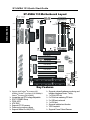
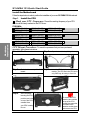
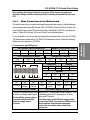
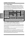
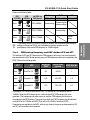
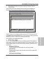
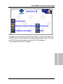
Introduction Quick BIOS Setup Hardware Installation SY-6VBA 133 Motherboard The SOYO CD Quick Start Guide Tested To Comply With FCC Standards FOR HOME OR OFFICE USE C FC 100% POST CONSUMER RECYCLED PAPER SOYO ™ SY-6VBA 133 Motherboard Pentium ® III, Pentium ® II & CeleronTM processors Via Apollo Pro133 AGP/PCI Motherboard 66/100/133 MHz Front Side Bus supported ATX Form Factor Copyright © 1999 bySoyo Computer Inc. Trademarks: Soyo is a registered trademark of Soyo Computer Inc. All trademarks are the property of their owners. Product Rights: Product and corporate names mentioned in this publication are used for identification purposes only and may be registered trademarks or copyrights of their respective companies. Copyright Notice: All rights reserved. This manual is copyrighted by Soyo Computer Inc. You may not reproduce, transmit, transcribe, store in a retrieval system, or translate into any language, in any form or by any means, electronic, mechanical, magnetic, optical, chemical, manual or otherwise, any part of this publication without express written permission of Soyo Computer Inc. Disclaimer: Soyo Computer Inc. makes no representations or warranties regarding the contents of this manual. We reserve the right to revise the manual or make changes in the specifications of the product described within it at any time without notice and without obligation to notify any person of such revision or change. The information contained in this manual is provided for general use by our customers. Our customers should be aware that the personal computer field is the subject of many patents. Our customers should ensure that their use of our products does not infringe upon any patents. It is the policy of Soyo Computer Inc. to respect the valid patent rights of third parties and not to infringe upon or assist others to infringe upon such rights. Restricted Rights Legend: Use, duplication, or disclosure by the Government is subject to restrictions set forth in subparagraph (c)(1)(ii) of the Rights in Technical Data and Computer Software clause at 252.277-7013. About This Guide: This Quick Start Guide is for assisting system manufacturers and end users in setting up and installing the Motherboard. Information in this guide has been carefully checked for reliability; however, no guarantee is given as to the correctness of the contents. The information in this document is subject to change without notice. If you need any further information, please visit our Web Site on the Internet. The address is "http://www.soyo.com.tw". 6VBA 133 Serial - Version 1.2 - Edition: September 1999 * These specifications are subject to change without notice 2 SY-6VBA 133 Quick Start Guide 1 Introduction This guide is designed for all users to provide the basic steps of Motherboard setting and operation. For further information, please refer to SY-6VBA 133 Motherboard User's Guide and Technical Reference online manual included on the CD-ROM packed with your Motherboard. Unpacking When unpacking the Motherboard, check for the following items: u The SY-6VBA 133 Via Apollo Pro133 AGP/PCI Motherboard u This Quick Start Guide u The Installation CD-ROM u SOYO 3-in-1 Bonus Pack CD-ROM (Norton AntiVirus, Ghost and Virtual Drive) u The CPU Retention Set u One IDE Device ATA 66 Flat Cable u One Floppy Disk Drive Flat Cable 3 Introduction Congratulations on your purchase of the SY-6VBA 133 Motherboard. This Quick Start Guide describes the steps for installing and setting up your new Motherboard. SY-6VBA 133 Quick Start Guide SY-6VBA 133 Motherboard Layout PS/2 KB Connector PS/2 Mouse Connector JP10 JP8 1 USB 1 USB 2 DIMM 1 DIMM 2 DIMM 3 DIMM 4 1 Slot 1 CPUFAN ® Introduction LED1 3 PRT FDC COM 1 COM 2 Via ATX Power 11 ® 82C693A JP9 1 AGP Slot PCI Slot #1 3V Lithium Battery ITE 8671 I/O Chipset 1 IR1 5 PCI Slot #2 JP2 JP5 1 PCI Slot #3 Via PCI Slot #4 ® 82C596B Speaker PCI Slot #5 JP7 + ISA Slot #1 828AC ISA Slot #2 Hardware Monitoring Keylock Power LED 1 Key Features Ø Supports Intel Pentium III processor (450® HDD + LED + Turbo LED PWRBT _ Winbond W83782M + Reset CHAFAN Ø Supports onboard hardware monitoring and includes Hardware Doctor ™ utility Ø 1 x 32-bit AGP slot Ø 5 x 32-bit bus mastering PCI slots Ø 2 x USB ports onboard Ø 1 x IrDA port Ø Supports multiple-boot function Ø Y2K Compliant Ø Supports Power Failure Resume 600MHz), Pentium® II processor (233-450MHz) & CeleronTM processor (266-433MHz) Ø Ø Ø Ø Ø Ø Ø _ 1 3 CMOS Clear Jumper _ 3 3 _ WOL Header Flash BIOS 1 JP44 1 IDE 2 IDE 1 Jumperless and CPU voltage Adjustable SOYO COMBO Setup PC98, ACPI ATA 33/66 Supports PC133 memory Power-on by modem or alarm Supports Wake-On-LAN (WOL) 4 SY-6VBA 133 Quick Start Guide 2 Installation l Before handling the Motherboard, ground yourself by grasping an unpainted portion of the system's metal chassis. l Remove the Motherboard from its anti-static packaging. Hold it by the edges and avoid touching its components. l Check the Motherboard for damage. If any chip appears loose, press carefully to seat it firmly in its socket. Follow the directions in this section designed to guide you through a quick and correct installation of your new SY-6VBA 133 Motherboard. For detailed information, please refer to SY-6VBA 133 Motherboard User's guide and Technical Reference online manual included on the CD-ROM packed with your Motherboard. PREPARATIONS Gather and prepare all the necessary hardware equipment to complete the installation successfully: u Slot 1 processor with built-in CPU cooling fan (boxed type) u SDRAM module u Computer case and chassis with adequate power supply unit u Monitor u PS/2 Keyboard u Pointing Device (PS/2 mouse) u VGA Card u Sound Card (optional) u Speaker(s) (optional) u Disk Drives: HDD, CD-ROM, Floppy drive … u External Peripherals: Printer, Plotter, and Modem- (optional) u Internal Peripherals: Modem and LAN cards (optional) 5 Hardware Installation To avoid damage to your Motherboard, follow these simple rules while handling this equipment: SY-6VBA 133 Quick Start Guide Install the Motherboard Follow the steps below in order to perform the installation of your new SY-6VBA 133 Motherboard. Step 1. Install the CPU Mark your CPU Frequency: Record the working frequency of your CPU that should be clearly marked on the CPU cover. FSB 66MHz 266MHz (66 x 4.0) 300MHz (66 x 4.5) 333MHz (66 x 5.0) 366MHz (66 x 5.5) 400MHz (66 x 6.0) 433MHz (66 x 6.5) 450MHz (100 x 4.5) 500MHz (100 x 5.0) 550MHz (100 x 5.5) 600MHz (100 x 6.0) 533MHz (133 x 4.0) 600MHz (133 x 4.5) 666MHz (133 x 5.0) 733MHz (133 x 5.5) FSB 100MHz 350MHz (100 x 3. 5) 400MHz (100 x 4.0) Hardware Installation FSB 133MHz 400MHz (133 x 3.0) 466MHz (133 x 3.5) CPU Mount Procedure: To mount the processor that you have purchased separately, follow these instructions. Retention Module Step 1. Open the two sides by folding them up. Step 2. Push the locks on top of the CPU inward. Step 4. After completely Step 3. Insert the CPU into the retention module. The CPU fits in the CPU slot in only ONE way, do not try to force it in. inserting the CPU, To remove the CPU, press the two notches on top of the CPU inward. Now press the two slides on the retention module down and remove the CPU. push the two locks on top of the CPU outward. Now your CPU is ready for use. 6 SY-6VBA 133 Quick Start Guide Note: Installing a heat sink and cooling fan on top of your CPU is necessary for proper heat dissipation. Failing to install these items may result in overheating and possible burn-out of your CPU. Make Connections to the Motherboard Step 2. This section tells how to connect internal peripherals and power supply to the Motherboard. Internal peripherals include IDE devices (HDD, CD-ROM), Floppy Disk Drive, Chassis Fan, Front Panel Devices (Turbo LED, Internal Speaker, Reset Button, IDE LED, and KeyLock Switch.), Wake-On-LAN card, VGA card, Sound Card, and other devices. Connectors and Plug-ins Pin1 VCC IrDA (Infrared Device Header): IR1 Pin2 Pin3 Pin4 Pin5 None IRRX GND IRTX CPU Cooling Fan: CPUFAN Pin1 Pin2 Pin3 GND 12V SENSOR Speaker Power LED Key Lock + 1 Reset _ _ 1 + 1 + _+ _ PWRBT Turbo LED HDD LED HDD LED Pin1 Pin2 LED LED Anode Cathode Wake-On-LAN Header: JP44 Pin1 Pin2 Pin3 5VSB GND MP-Wakeup Chassis Fan: CHAFAN Pin1 Pin2 Pin3 GND 12V SENSOR Power LED Keylock Pin1 Pin2 Pin1 Pin2 Pin3 GND 5V NC GND Control Pin Speaker Pin1 Pin2 Pin3 Pin4 5V NC NC Speaker out Turbo LED Pin1 Pin2 LED GND Cathode PWRBT RESET Pin1 Pin2 Pin1 Pin2 Power GND Power Good GND On/Off ATX Power Supply: ATX PW ATX Power On/Off: PWRBT Connect your power switch to this Attach the ATX Power cable to this connector. (This header (momentary switch type). motherboard requires an ATX power supply, an AT power To turn off the system, please supply can NOT be used.) press this switch and hold Note: Please make sure the ATX power supply is able to provide at least 720mA of current on the +5VSB lead if you down for longer than 4 seconds. want to enable the advanced power management functions, like power failure resume, Power-On by keyboard, etc. 7 Hardware Installation For more details on how to connect internal and external peripherals to your new SY-6VBA 133 Motherboard, please refer to SY-6VBA 133 Motherboard User's Guide and Technical Reference online manual on CD-ROM. SY-6VBA 133 Quick Start Guide Step 3. Configure Memory Your board comes with four DIMM sockets, providing support for up to 1.5GB of main memory using unbuffered and registered DIMM modules from 8MB to 256/512MB. On this motherboard, DRAM speed can be set independent from the CPU front side bus speed. Depending on the DRAM clock speed setting in the BIOS setup (Chapter 3), appropriate memory modules must be used. For 66MHz DRAM speed, use PC66 memory; for 100MHz DRAM speed, use PC100 memory; for 133MHz DRAM speed, use PC133 memory. Memory Configuration Table Number of Memory Modules DIMM 1 DIMM 2 DIMM 3 1st Hardware Installation 1 2nd 1st 3rd 2nd 1st 3rd 2nd 1st 2 3 4 4th RAM Type Memory Module Size (MB) DIMM 4 SDRAM 8/16/32/64/128/256/512 MB (For DIMM1& DIMM2) 8/16/32/64/128/256 MB (For DIMM3 & DIMM4) Note:Always install memory modules in the order prescribed in this table. Step 4. CPU B21 and A14 Settings: JP8 and JP9 For certain Intel CPUs, the multiplier is not locked such that setting a multiplier higher than specified on the CPU is possible. For technical details read the following: Your PII /III 100/66 MHz FSB CPU has an input pin B21 (100/66# signal) to tell it what FSB frequency it is running at; The PIII 133 MHz FSB CPU has two pins B21and A14 (133/100# signal). JP8 and JP9 are connected to the B21 and A14 input respectively and are used to tell CPU its FSB speed. The actual FSB Frequency is however set through the BIOS and it may therefore differ from the Frequency specified to the CPU through JP8 & JP9. Because some INTEL CPUs have their multipliers limited at a FSB Frequency of 100MHz and higher, telling the CPU that it is running at 66MHz through JP8 & JP9 while setting a different (higher) FSB Frequency in the BIOS may allow the user to set a higher multiplier value. Doing so will however force your CPU to operate out of its specifications, and therefore SOYO can not guarantee the proper functioning of your system. 8 SY-6VBA 133 Quick Start Guide Refer to the following table: JP9 133/100# Short JP8 100/66# Short 1 2 Short Normal setting *Possible higher multiplier setting FSB = 66MHz Open Normal setting FSB = 100MHz 1 2 Open 1 2 PII,PIII PIII 100MHz FSB 133MHz FSB 1 2 1 2 Open PII, Celeron 66MHz FSB tell CPU its FSB Speed Normal setting FSB = 133MHz 1 2 settings on some Intel CPUs, but it will make the system operate out of its specifications if the actual FSB frequency is 100MHz higher. FSB boot-up frequency and AGP divider: JP2 and JP7 Step 5. The settings of JP2 and JP7 determine the FSB frequency at boot-up, and more important, they determine the AGP divider and the group of FSB frequencies that can be selected in the BIOS. Refer to the following table: JP7 Short JP2 Short Pin 1-2 1 2 Open Short pin 1-2 AGP divider 66 66~83 1 100 90~122 1.5 133 124~155 2.0 1 2 3 Short pin 2-3 1 2 BIOS FSB group 1 2 3 1 2 Open Boot-up FSB 1 2 3 As example, if JP7 is set to open and JP2 to (1-2), the boot-up FSB frequency will be 100MHz. When the BIOS takes control, it will write the BIOS FSB setting to the clock generator. This happens shortly after power-up, and the FSB frequency will then be in accordance to the BIOS setting. The group from which the FSB Frequency can be selected in the BIOS is 90~122MHz and AGP Clock will be 60~81MHz. Note that all FSB Frequencies are available in the BIOS, but that only those in the group as determined by JP2 and JP7 will have effect when selected. 9 Hardware Installation * This setting will tell CPU that it is running on 66MHz; this will release more multiplier SY-6VBA 133 Quick Start Guide Step 6. Set the CPU Frequency You do not need to set any jumper for the CPU frequency. Instead, CPU settings are changed through the BIOS [SOYO COMBO SETUP]. Please refer to Chapter 3 - Quick BIOS Setup for details on how to set the Slot 1 processor frequency. Step 7. External Suspend Button (JP1) Some cases come with a suspend button, insert the plug into JP1. In addition to this button, the system can also enter the suspend mode through your OS. Hardware Installation Note: Suspend mode only functions if your Power Management mode is APM. Make sure that the BIOS setting for Power Management is APM. Windows 98 can be installed with ACPI Power Management (default is APM), in this case suspend mode will not function either. Step 8. Enable/Disable Power-On by Keyboard (JP10) You can choose to enable the Power-On by Keyboard function by shorting pin 1-2 on jumper JP10, otherwise, short pin 2-3 to disable this function. Power-On by Keyboard Enable Short pin 1-2 to enable the JP10 Setting Power-On by Keyboard function. Disable 1 2 3 Short pin 2-3 to disable the Power-On by Keyboard function. 1 2 3 Important: When using the Power-On by Keyboard function, please make sure the ATX power supply can take at least 720mA load on the 5V Standby lead (5VSB) to meet the standard ATX specification. Step 9. 5V Stand-by indicator LED (LED 1) This LED is lit whenever the 5V Standby voltage coming from the ATX powersupply is available. If you have connected your ATX powersupply to the mains, LED 1 should be lit. 10 SY-6VBA 133 Quick Start Guide Step 10. Clear CMOS Data (JP5) Clear the CMOS memory by momentarily shorting pin 2-3 on jumper JP5 for at least 5 seconds, and then by shorting pin 1-2 to retain new settings. This jumper can be easily identified by its white colored cap. CMOS Clearing JP5 Setting Clear CMOS Data Short pin 2-3 for at least 5 seconds to clear the CMOS. Retain CMOS Data Short pin 1-2 to retain the new settings. 1 2 3 1 2 3 Note on Over-clocking Capability The SY-6VBA 133 provides over-clocking capability. Due to the over-clocking setting your system may fail to boot up or hang during run time. Please perform the following steps to recover your system from the abnormal situation : 1.Turn off system power (If you use an ATX power supply, and depending on your system, you may have to press the power button for more than 4 seconds to shut down the system.) 2.Set the JP8 and JP9 to short if you use a FSB 66MHz CPU 3.Press and hold down the <Insert> key while turning on the system power. Keep holding down the <Insert> key until you see the message of the CPU type and frequency shown on the screen. 4.Press the <Del> key during the system diagnostic checks to enter the Award BIOS Setup program. 5.Select [SOYO COMBO SETUP] and move the cursor to the [CPU Frequency] field to set the proper working frequency. 6.Select [Save & Exit SETUP] and press <Enter> to save the new configuration to the CMOS memory, and continue the boot sequence. Note: SOYO does not guarantee system stability if the user over clocks the system. Any malfunctions due to over-clocking are not covered by the warranty. 11 Hardware Installation Note: You must unplug the ATX power cable from the ATX power connector when performing the CMOS Clear operation. SY-6VBA 133 Quick Start Guide 3 Quick BIOS Setup This Motherboard does not use any hardware jumpers to set the CPU frequency. Instead, CPU settings are software configurable with the BIOS [SOYO COMBO SETUP]. The [SOYO COMBO SETUP] menu combines the main parameters that you need to configure, all in one menu, for a quick setup in BIOS. After the hardware installation is complete, turn the power switch on, then press the <DEL> key during the system diagnostic checks to enter the Award BIOS Setup program. The CMOS SETUP UTILITY will display on screen. Then, follow these steps to configure the CPU settings. Step 1. Select [STANDARD CMOS SETUP] Set [Date/Time] and [Floppy drive type], then set [Hard Disk Type] to “Auto”. Step 2. Select [LOAD SETUP DEFAULT] Select the “LOAD SETUP DEFAULT”menu and type “Y”at the prompt to load the BIOS optimal setup. Step 3. Select [SOYO COMBO SETUP] Quick BIOS Setup Move the cursor to the [CPU Frequency] field to set the CPU frequency. Available [CPU Frequency] settings on your SY-6VBA 133 Motherboard are detailed in the following table. CPU Frequency (MHz) 500MHz( 66 x 7.5) 750MHz (100 x 7.5) Manual 533MHz ( 66 x 8.0) 800MHz (100 x 8.0) 200MHz (66 x 3.0) 300MHz (100 x 3.0) 400MHz (133 x 3.0) 233MHz (66 x 3.5) 350MHz (100 x 3.5) 466MHz (133 x 3.5) 266MHz (66 x 4.0) 400MHz (100 x 4.0) 533MHz (133 x 4.0) 300MHz (66 x 4.5) 450MHz (100 x 4.5) 600MHz (133 x 4.5) 333MHz (66 x 5.0) 500MHz (100 x 5.0) 666MHz (133 x 5.0) 366MHz (66 x 5.5) 550MHz (100 x 5.5) 733MHz (133 x 5.5) 400MHz (66 x 6.0) 600MHz (100 x 6.0) 800MHz (133 x 6.0) 433MHz (66 x 6.5) 650MHz (100 x 6.5) 866MHz (133 x 6.5) 466MHz ( 66 x 7.0) 700MHz(100 x 7.0) ® 933MHz (133 x 7.0) ® Select the working frequency of your Pentium III, Pentium II, Celeron processor among these preset values. Note: Mark the checkbox that corresponds to the working frequency of your Pentium® III, Pentium® II, Celeron processor in case the CMOS configuration should be lost. 12 SY-6VBA 133 Quick Start Guide If you set this field to [Manual], you are then required to fill in the next two consecutive fields: (1) the CPU Host/PCI Clock, and (2) the CPU Ratio. (1) CPU Host/PCI Clock CPU Host / PCI Clock o66/33 o75/37 o78/39 o81/40 o83/41 o90/30 o95/31 o115/38 o124/41 o140/35 Under this item you find the frequencies your PCI slots run at. o100/33 o117/39 o126/31 o142/35 o105/35 o118/39 o133/33 o144/36 o110/36 o120/40 o135/33 o150/37 o112/37 o122/37 o137/34 o155/38 o113/37 o124/31 o138/34 (2) CPU Ratio After you have selected the CPU Host/ PCI Clock, choose the right multiplier for the CPU. CPU Ratio options are: o x 2.5 o x5 o x 7.5 o x3 o x 5.5 o x8 o x 3.5 o x6 o x4 o x 6.5 The CPU frequency is then defined as [host clock freq.] x [multiplier], and should equal the working frequency of your CPU. (3) DRAM Clock Now select the DRAM clock source. It is derived form the CPU FSB clock and it can, depending on the BIOS setting, be: Ø Equal to the CPU FSB clock Ø CPU FSB clock –PCI clock Ø CPU FSB clock + PCI clock As an example: If the user sets the CPU Host/PCI clock to 105/35 MHz, the options will be: Ø Equal to the CPU FSB clock = 105 MHz Ø CPU FSB clock –PCI clock = 70 MHz Ø CPU FSB clock + PCI clock = 140 MHz Depending on the DRAM speeds, the user can select one of these speeds through the BIOS. 13 Quick BIOS Setup o x2 o x 4.5 o x7 SY-6VBA 133 Quick Start Guide (4) AGP Clock The AGP clock is derived from the CPU FSB frequency. It is divided by 1.0, 1.5 or 2.0 depending on the setting of JP2 and JP7: Please refer to page 9 for the JP2 and JP7 settings. (5) Vcore Voltage Adjust The CPU notifies the board of what core voltage it requires by its VID outputs. The on-board voltage regulator uses the VID code to set the core voltage. If the Vcore Voltage Adjust is set to normal, the Vcore will be exactly what the VID code specifies. If an adjustment percentage is selected the Vcore will be that percentage higher than the VID code specifies. For instance the CPU VID code specifies 2.0V and the Vcore Voltage adjust is set to +10.0% the actual CPU Voltage will be 2.2V. This function should only be used if the CPU is running on FSB Frequencies beyond the CPU specifications, note that SOYO does not guarantee system stability if this item is not set to normal. o Normal Quick BIOS Setup Step 4. o + 2.5 % o + 5.0 % o + 7.5% o +10.0 % Select [SAVE & EXIT SETUP] Press <Enter> to save the new configuration to the CMOS memory, and continue the boot sequence. 14 SY-6VBA 133 Quick Start Guide The SOYO CD 4 The SOYO-CD will NOT autorun if you use it on an Operating System other than Windows 9x or NT. Your SY-6VBA 133 Motherboard comes with a CD-ROM labeled "SOYO CD." The SOYO CD contains the user's manual file for your new Motherboard, the drivers software available for installation, and a database in HTML format with information on SOYO Motherboards and other products. Step 1. Insert the SOYO CD into the CD-ROM drive The SOYO CD The SOYO CD will auto-run, and the SOYO CD Start Up Menu will display as shown below. (SOYO CD Start Up Program Menu) If you use Windows 95/98, the SOYO CD Start Up Program automatically detects which SOYO Motherboard you own and displays the corresponding model name. Step 2. Read SOYO [6VBA 133] Manual Click the Read Manual button to open the user's manual file of your Motherboard. 15 SY-6VBA 133 Quick Start Guide Please note that if the Start Up program was unable to determine which SOYO Motherboard you own, the manual selection menu will pop up, as shown below. Then select the user's manual file that corresponds to your Motherboard model name and click OK. SOYO CD Manuals Please select your manual in the box below and click OK. 686 boards: 586 boards: 6VBA 133 OK Back (Manual Selection Menu) The SOYO CD The user's manual files included on the SOYO CD can be read in PDF (Postscript Document) format. In order to read a PDF file, the appropriate Acrobat Reader software must be installed in your system. Note: The Start Up program automatically detects if the Acrobat Reader utility is already present in your system, and otherwise prompts you on whether or not you want to install it. You must install the Acrobat Reader utility to be able to read the user's manual file. Follow the instructions on your screen during installation, then once the installation is completed, restart your system and re-run the SOYO CD. Step 3. Install Drivers The following describes the best way of installing Windows 95 or Windows 98 on your 6VBA 133 Motherboard: Ø The following BIOS default settings should not be changed: 1. The ‘OnChip USB Controller’item under ‘Chipset features Setup’is set to enabled. 2. The ‘USB Assigned IRQ’item under ‘PnP/PCI Configuration is set to enabled. You MUST have these two items enabled for Windows 95/98 to run properly on your system. Ø Install Windows 95/98 Ø If you installed Windows 95 you will now need to upgrade your USB driver by running the following program on your Windows CD: Win95/OSR2/Usbsupp/USBsupp.exe 16 SY-6VBA 133 Quick Start Guide After installation of windows, you will need to install the VIA drivers. Follow the instructions below. Ø Click the Install drivers button to display the list of drivers that can be installed on your Motherboard. The start-up program displays the drivers available for the 6VBA 133. Driver Installation Please select the driver you want to install and click OK, Yu will have to restart your system after installation. Only the drivers that are relevant to your board are displayed initially. VIA 4 in 1 driver package 6VBA 133 Winbond hardware doctor for win 95/98 Cancel Display all drivers on the SOYO CD OK (Driver Installation Menu) A short description of all available drivers follows: VIA 4in1 driver package Ø The 4 in 1 driver package includes all drivers your motherboard needs. After selecting this driver package, one driver will be installed automatically (the IRQ remapping utility), the other three are installed if selected. By default all three drivers are selected. A description of the 4 drivers follows: Bus Master PCI IDE Driver This driver will speed up the data-transfer rate to and from the harddisk. AGP VxD Driver This driver must be installed in order to be able to make use of the on-board AGP Video functionality. VIA Chipset Functions Registry 17 The SOYO CD However, to display the list of all drivers software available with SOYO Motherboards, click the Display all drivers on the SOYO CD button. Please make sure to install only the drivers adapted to your system, or otherwise this cause system malfunctions. SY-6VBA 133 Quick Start Guide This driver will make the necessary changes to the Windows registry, in order to make sure that Windows has no problems recognizing your VIA chipset. Ø IRQ remapping utility (This driver is installed automatically) This utility will remap the IRQ lines to make sure that everything functions properly under Windows. Winbond hardware doctor for Windows 9x Your motherboard comes with a hardware monitoring IC. By installing this utility Temperature, Fan speed and Voltages can be monitored. It is also possible to set alarms when current system values exceed or fall below pre-set values. This utility comes with a preset monitoring rage for the CPU voltage. However, the core voltage of the processor you purchased may fall out of this preset range, so you may need to adjust the pre-set value. Please refer to the SY-6VBA 133 Motherboard’s CD manual for the details. Select which driver you want to install and click OK, or click Cancel to abort the driver installation and return to the main menu. Note: Once you have selected a driver, the system will automatically exit the SOYO CD to begin the driver installation program. When the installation is complete, most drivers require to restart your system before they can become active. Step 4. Check the Latest Releases Click the 'Check the latest Releases' button to go the SOYO Website to automatically find the latest BIOS, manual and driver releases for your motherboard. This button will only work if your computer is connected to the internet through a network or modem connection. Make sure to get your modem connection up before clicking this button. The SOYO CD Step 5. Enter the SOYO CD Click the Enter SOYO CD button to enter the SOYO HTML database. The Start Up program will activate the default HTML browser installed on your system (for example, Internet Explorer or Netscape) to visualize the contents of the SOYO CD. The SOYO CD contains useful information about your Motherboard and other SOYO products available. For your convenience, this information is available in HTML format, similar to the format widely used on the Internet. 18 SY-6VBA 133 Quick Start Guide The SOYO CD Note: If no HTML browser is installed on your system, the Start Up program will prompt you on whether or not you would like to install the Internet Explorer* browser. Click YES to install the HTML browser. After the installation is complete, please restart your system. Then re-run the SOYO CD and you will be able to browse the SOYO HTML database. (* Internet Explorer is a Microsoft Trademark) 19 SY-6VBA 133 Quick Start Guide How to contact us: n If you are interested in our products, please contact the SOYO sales department in the region you live. n If you require Technical Assistance, please contact our Technical Support in the region you live. SOYO prefers Email as communication medium, remember to always add to the email the country that you live in. SOYO Taiwan No. 21 Wu-Kung 5 Rd., Hsin Chuang City, Taipei Hsien, Taiwan SOYO USA 41484 Christy Street, Fremont, CA 94538 Region Covered: US and Canada Region Covered: Taiwan and AsiaPacific. (Including Australia). Web Site: www.soyo.com.tw Web Site: www.soyousa.com, www.soyo.com Sales: Tel: 510-226-7696 Fax: 510-226-9218 Email : [email protected] Sales: Tel: 886-2-22903300-318 Fax: 886-2-22983322 E-mail: [email protected] Technical Support: Tel: 510-226-7696 Fax: 510-226-9218 Email : [email protected] Technical Support: Fax: 886-2-22983322 E-mail: [email protected] SOYO Europe BV Signaalrood 19, 2718 SH Zoetermeer The Netherlands Region Covered: Europe except Germany, Austria and Switserland Web Site: www.soyo.nl, www.soyoeurope.com Sales: Tel: +31-69-3637500 Fax: +31-79-3637575 Email: [email protected] SOYO (U.K.) LTD. Unit 7, Alice Way, Hounslow Business Park, Hanworth Road, Hounslow, TW3 3UD Region Covered: United Kingdom and Republic of Ireland Web Site: www.soyo.co.uk Sales: Tel : +44 (0)181 569 4111 Fax: +44 (0)181 569 4134 E-mail: [email protected] Technical Support: Tel : +31-79-3637500 Fax: +31-79-3637575 Email: [email protected] Technical Support: Tel : +44 (0)181 569 4111 Fax: +44 (0)181 569 4134 20 SY-6VBA 133 Quick Start Guide E-Mail: [email protected] Sales: tel: 852-27109810 fax: 852-27109078 E-mail: [email protected] SOYO Deutschland GmbH August-Wilhelm-Kuhnholz-Str. 15 D-26135 Oldenburg Technical Support: tel: 852-27109810 fax: 852-27109078 E-mail: [email protected] Region Covered: Germany, Austria and Switzerland. (Zustandig fur Deutschland, Osterreich, Schweiz) Web Site: www.saat.de, www.soyosaat.com, www.soyo-saat.de Vertrieb Mainboards, Notebooks und SoyoCom Produkte: E-Mail: [email protected] Fon: +49-(0)441/20910-31/33 Fax: +49-(0)441/203422 SOYO China (Gin Mei Jei) Region Covered: All of China Sales: Tel: 86-10-62510089 fax: 86-10-62510388 E-mail: [email protected] Technischer Support: E-Mail: [email protected] Fon: +49-(0)441/20910-40 Fax: +49-(0)441/203422 Technical Support: Tel: 86-10-62510089 fax: 86-10-62510388 E-mail: [email protected] SOYO KOREA Region Covered: Korea SOYO Japan Region Covered: Japan Sales: Tel : 82-2-716-2850 Fax : 82-2-704-2619 E-mail : [email protected] Web site: www.soyo.co.jp Sales: Tel: 81-3-33682188 Fax: 81-3-33682199 E-mail: [email protected] Technical Support: tel : 82-2-717-4392 fax : 82-2-712-5853 e-mail : [email protected] Technical Support: Tel: 81-3-33682188 Fax: 81-3-33682199 E-mail: [email protected] SOYO Hong Kong Region Covered: Hong Kong Web Site: www.soyo.com.hk 21 Edition: September 1999 Version 1.2 SY-6VBA 133 SERIAL