1
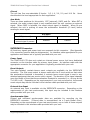
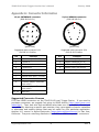
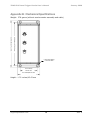
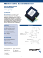
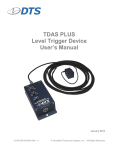
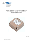
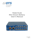
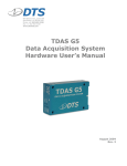
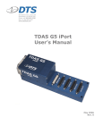
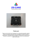
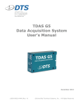
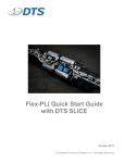
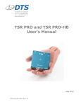
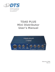
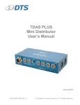
TDAS PLUS
Level Trigger Device
User’s Manual
January 2006
Rev. 0
TDAS PLUS Level Trigger Device User’s Manual
January 2006
Table of Contents
DTS Support .................................................................................................... 3
Introducing the TDAS PLUS Level Trigger Device ............................................ 4
Overview of TDAS PLUS Level Trigger Device Features ................................... 4
Control Panel................................................................................................ 4
Filter (Hz)................................................................................................. 4
G Level .................................................................................................... 5
Arm Mode ................................................................................................ 5
INTERFACE Connector ................................................................................... 5
Power Input.............................................................................................. 5
Event Outputs ........................................................................................... 5
External Arm Input .................................................................................... 5
Accelerometer Data ................................................................................... 5
G SENSOR Connector .................................................................................... 6
External Accelerometer .............................................................................. 6
Basic Care and Handling ................................................................................. 6
Shock Rating ................................................................................................ 6
Mounting Considerations............................................................................. 6
Thermal Considerations ................................................................................. 7
Power Management ........................................................................................ 7
External Power Provisions............................................................................... 7
Power-up and Power-down Procedures ............................................................. 7
Communication Features ................................................................................ 7
LED Indicators .............................................................................................. 7
Appendix A: Connector Information ............................................................... 9
Suggested Connector Sources......................................................................... 9
Appendix B: Mechanical Specifications......................................................... 10
Appendix C: Accelerometer Specifications ................................................... 11
[email protected]
ii
Rev. 0
TDAS PLUS Level Trigger Device User’s Manual
January 2006
DTS Support
TDAS systems are designed to be reliable and simple to operate. Should you need
assistance, DTS has support engineers worldwide with extensive product knowledge
and crash test experience to help via telephone, e-mail or on-site visits.
The best way to contact a DTS support engineer is to e-mail [email protected].
Your e-mail is immediately forwarded to all DTS support engineers worldwide and is
typically the fastest way to get a response, particularly if you need assistance outside
of normal business hours.
For assistance by telephone, please go to
http://www.dtsweb.com/support.html to find the phone number appropriate for your
region of the world.
[email protected]
3
Rev. 0
TDAS PLUS Level Trigger Device User’s Manual
January 2006
Introducing the
TDAS PLUS Level Trigger Device
The TDAS PLUS Level Trigger Device (LTD) is a crashworthy device that provides an
opto-isolated, contact-closure event output when a predetermined acceleration
threshold is exceeded. The TDAS PLUS Level Trigger Device will initiate data collection
or event trigger when used with TDAS PRO, TDAS G5, or TDAS PLUS equipment. The
TDAS PLUS LTD can also be used with any other system or device capable of receiving
a contact-closure event signal.
This manual discusses the features available with the TDAS PLUS Level Trigger Device.
To identify the specific hardware included with your system, please see your packing
list.
Overview of TDAS PLUS Level Trigger Device Features
•
•
•
•
•
•
•
Built and tested for 100+ G dynamic testing environments.
User-selectable filter values, G levels, and arm mode.
Overvoltage protection, overcurrent protection, power input polarity
protection and event overvoltage protection.
User-replaceable external accelerometer in case of accidental damage.
Use with any TDAS PRO rack, TDAS G5 Docking Station, TDAS PLUS Mini
Distributor, fully-featured TDAS PLUS Distributor or any other device capable
of receiving a contact-closure event signal.
Operates on nominal 12 VDC power (11-15 volt range).
Integral mounting flanges.
An interface cable appropriate for your application and feature set is typically provided
with your unit. Please see your interface cable for the specific features included with
your device.
Control Panel
The control panel on the TDAS PLUS LTD allows you to select the operational
parameters for the unit. Keys to change switch position are supplied with the unit,
however a simple flat-head screwdriver can also be used. The keys must be removed
from the unit prior to performing a test.
Filter (Hz)
Five filter options are available: 50, 100, 200, 500, and 1000 Hz. Users should select
the highest value appropriate for their application while keeping in mind that:
•
•
The higher the value, the faster the response time,
The lower the value, the less chance of a false trigger.
[email protected]
4
Rev. 0
TDAS PLUS Level Trigger Device User’s Manual
January 2006
G Level
The unit has five user-selectable G levels: 0.5, 1.0, 2.0, 5.0, and 10.0 Gs.
should select the level appropriate for their application.
Users
Arm Mode
There are three positions for this switch: EXT (external), SAFE, and Gs. When EXT is
selected, the event output signal is only enabled when the unit receives an external
signal. When SAFE is selected, the event output signal is disabled. When Gs are
selected, the unit is waiting to sense the acceleration threshold (G Level) before
sending an event signal.
Arm Mode
EXT (external)
SAFE
Gs
Enabled only when
external signal is present
Disabled
Enabled
INTERFACE Connector
All functions, signals and power input are accessed via this connector. (See Appendix
A for connector specifics and pin assignments.) An interface cable appropriate for your
application and feature set is typically provided with your unit.
Power Input
The TDAS PLUS LTD does not contain an internal power source but has a dedicated
connector on the interface cable for primary input power. An interface cable with the
appropriate connector for your application is typically provided with your unit.
Event Outputs
Two opto-isolated, contact-closure event outputs are available via the INTERFACE
connector. The first event output is always used with the G Level switch so that when
the acceleration threshold is exceeded, a contact-closure event signal is sent to any
attached equipment that can receive such a signal. The duration of the signal depends
upon the length of time that the acceleration threshold is exceeded (i.e., as long as the
T=0 LED is on). Depending on the requirements of your test environment, the second
event output may also be included in the interface cable provided with your unit.
External Arm Input
An external arm input is available via the INTERFACE connector. Depending on the
requirements of your test environment, this input may be included in the interface
cable provided with your unit.
Accelerometer Data
Filtered and unfiltered accelerometer data are available for recording via the
INTERFACE connector. (Filtered data is accomplished via a 2-pole Bessel filter.)
Depending on the requirements of your test environment, one or both of these outputs
may be included in the interface cable provided with your unit.
[email protected]
5
Rev. 0
TDAS PLUS Level Trigger Device User’s Manual
January 2006
G SENSOR Connector
This connector is dedicated for use with the accelerometer provided with the unit. See
Appendix A for connector specifics and pin assignments.
External Accelerometer
Should it be necessary, the external accelerometer can be replaced by the user. See
Appendix C for accelerometer specifics and sourcing information.
Basic Care and Handling
The TDAS PLUS Level Trigger Device is a precision device designed to operate reliably
in dynamic testing environments. Though resistant to many environmental conditions,
care should be taken not to subject the unit to harsh chemicals, submerge it in water,
or drop it onto any hard surface.
WARNING:
Electronic equipment dropped from desk height onto a solid
floor may experience as much as 10,000 Gs. Under these
conditions, damage to the exterior and/or interior of the unit is
likely.
When transporting the unit, treat it as you might a laptop computer and you should
have no problems. When not in use or if shipping is required, we suggest that you
always place the unit in the padded carrying case originally provided with your system.
The TDAS PLUS LTD is not user-serviceable and should be returned to the factory for
service or repair. The external accelerometer, however, can be purchased separately
and replaced by the user. See Appendix C for accelerometer specifics and sourcing
information.
Shock Rating
All crashworthy TDAS PLUS systems are rated for and fully tested to 100+ Gs, 12 msec
duration, in all axes and can be mounted directly on a vehicle, sled or other dynamic
testing device.
Mounting Considerations
The unit should be securely bolted to the vehicle, sled or other dynamic testing device
to provide the best shock protection and facilitate proper grounding. Mounting
methods and mounting bolt selection should be carefully calculated so as to withstand
expected shock loading. (See Appendix B for the unit’s mechanical specifications.)
The external accelerometer should be mounted on the test fixture in the sensitive axis
as indicated on the accelerometer block.
[email protected]
6
Rev. 0
TDAS PLUS Level Trigger Device User’s Manual
January 2006
Thermal Considerations
It is extremely unlikely that excessive heating will ever be an issue in real-world
testing applications using the TDAS PLUS Level Trigger Device. Should you have any
questions about its use in your environment, please contact DTS.
Power Management
A good power source is of paramount importance. Each TDAS PLUS Level Trigger
Device should be powered from a fully-charged 12-volt battery or a high-quality power
supply with a nominal output voltage of 12 volts (11-15 volt range) and a capacity of
at least 50 mA. When assessing power requirements, please consider any voltage
drops that may occur due to cables, connectors, power converters, etc.
External Power Provisions
The TDAS PLUS LTD does not contain an internal power source but has a dedicated
connector on the interface cable for primary input power. The voltage required to
power the unit can be supplied in two ways: 1) directly from a 12-volt battery (e.g.,
TDAS PLUS Crashworthy Battery), or 2) connecting the unit to a TDAS PLUS
Distributor. An interface cable with the appropriate connector for your application is
typically provided with your unit.
Power-up and Power-down Procedures
Whenever the unit is connected to sufficient power, it will power up. Whenever power
is disconnected from the unit, it will power down. Power up and power down is
immediate upon application or removal of the power source.
Communication Features
The TDAS PLUS Level Trigger Device communicates via two LED indicators. The device
does not support direct PC communications.
LED Indicators
The TDAS PLUS LTD has two LED indicators that provide power and acceleration
threshold (G Level) information.
LED Status
PWR (green LED)
T=0 (red LED)*
Off
No power, insufficient power, or
external accelerometer is not
connected
Acceleration threshold
not reached
On
Power OK
Acceleration threshold reached
or exceeded
* Always enabled when unit is powered, regardless of Arm Mode (i.e., non-latching).
[email protected]
7
Rev. 0
TDAS PLUS Level Trigger Device User’s Manual
January 2006
WARNING:
If the GREEN power LED on the TDAS PLUS Level Trigger
Device goes dark unexpectedly during the performance of a
test, the test should be aborted if this can be done in a safe
manner.
[email protected]
8
Rev. 0
TDAS PLUS Level Trigger Device User’s Manual
January 2006
Appendix A: Connector Information
12-pin INTERFACE connector
(EGG.2B.312.CLL)
3
1
8
1
2
5-pin G SENSOR connector
(EGG.1B.305.CLL)
9
12
10
11
4
2
7
3
6
4
5
(panel view)
(panel view)
Suggested cable connector P/N:
FGG.2B.312.CLADxx
Pin
5
Suggested cable connector P/N:
FGG.1B.305.CLADxx
Function
Pin
Function
1
+ Power in (11-15 VDC)
1
- Power out (VDC)
2
- Power in
2
Sensor reference (2.5 V)
3
+ Event out 1
3
+ Power out (VDC)
4
- Event out 1
4
Sensor input (100 mV/G)
5
+ Event out 2
5
Shield (case)
6
- Event out 2
7
External arm input (+5 VDC)
8
Common
9
+ Sensor output, unfiltered
(100 mV/G)
10
11, 12
+ Sensor output, filtered
(100 mV/G)
Reserved
Suggested Connector Sources
DTS uses LEMO connectors on the TDAS PLUS Level Trigger Device. If you need to
purchase connectors, we suggest first going to LEMO directly (http://www.lemo.com/
index.html). Their web site and worldwide sales team are very helpful. Should you
have difficulty obtaining a specific part number, they can suggest connector variations
or alternates and explain options that may be useful for your particular application.
Another U.S. source is Alpine Electronics (www.alpine-electronics.com) in San Jose,
California. They are a stocking distributor for LEMO and LEMO-compatible connectors.
[email protected]
9
Rev. 0
TDAS PLUS Level Trigger Device User’s Manual
January 2006
Appendix B: Mechanical Specifications
Weight: 278 grams (without accelerometer assembly and cable)
4.98 inches/126.49 mm
5.28 inches/134.11 mm
0.25 inches diam/
6.35 mm diam
2.00 inches/
50.80 mm
2.6 inches/66.04 mm
Height: 1.71 inches/43.43 mm
[email protected]
10
Rev. 0
Model 4000 Accelerometer
Piezoresistive MEMS Accelerometer
Signal Conditioned Output
Temperature Calibrated
Low Cost, Light Weight
DESCRIPTION
The Model 4000 is an economical signal
conditioned accelerometer with integral
temperature compensation. The accelerometer
incorporates a 2nd generation piezoresistive
MEMS sensor providing outstanding performance.
The accelerometer is packaged in a light weight
thermoplastic housing ideal for transportation and
instrumentation testing. The signal conditioned
output incorporates a 2.5V reference that offers
the user a differential or single-ended output.
dimensions
FEATURES
✦ ±2g to ±200g Dynamic Range
✦ High Over-Range Protection
✦ Signal Conditioned Output
✦ Low Power Consumption
✦ Light Weight Plastic Housing
✦ Gas Damping
✦ Integral Cable – Connector Options
APPLICATIONS
✦ Low Frequency Monitoring
✦ Transportation
✦ Vibration Sensing
✦ Test & Instrumentation
Measurement Specialties, Inc.
1000 Lucas Way
Hampton, VA 23666 USA
www.meas-spec.com
Customer Service:
Tel: 1-757-766-1500 (Toll Free:
1-800-745-8008)
Fax: 1-757-766-4297
Vibration Sensors Technical
Support:
Tel: 1- 949-716-5377
Fax: 1- 949-916-5677
Email: [email protected]
RevA 1/19/06
-1-
Model 4000 Accelerometer
performance specifications
All values are typical at 25°C, 100Hz and 12Vdc excitation unless otherwise stated. Measurement Specialties reserves the right to update and
change these specifications without notice.
Parameters
DYNAMIC
Range
Sensitivity
Frequency Response
±2
1000
0-250
±5
400
0-400
±10
200
0-500
Range
Sensitivity
Frequency Response
±50
40
0-1000
±100
20
0-1500
Non-Linearity
Transverse Sensitivity (Max)
Zero Acceleration Output
Thermal Zero Shift (-20 to +85°C)
Thermal Sensitivity Shift
(-20 to +85°C)
ELECTRICAL
Excitation Voltage
Excitation Current
Reference Voltage
Output Impedance
Insulation Resistance (@ 50Vdc)
Ground Isolation
PHYSICAL
Housing
Weight (cable not included)
Mounting
ENVIRONMENTAL
Shock Limit
Operating Temperature
Humidity
±20
100
0-800
Units
mV/g
Hz
Notes
±200
10
0-1500
Units
mV/g
Hz
Notes
±1
±3
2.50±.05
±.028
±.028
% FSO
%
V
% FSO/ºC
%/ºC
Maximum
±1% Typical
10 to 24
5.0
2.5
100
100
Isolated
Vdc
mA
Vdc
Ω
MΩ
High Performance Thermoplastic
8
2x #4 or M3 Screws
5,000
-20 to +85
Epoxy Sealed
grams
±5%
±5%
Maximum
Maximum
Typical
Maximum
Minimum
Maximum
3 lb-in mounting torque
g’s
°C
Contact factory for custom temperature compensation options.
electrical schematic
o rd e r i n g i n f o r m a t i o n
4000-100-060
Cable Length (in)
Range (g)
Model
Measurement Specialties, Inc.
1000 Lucas Way
Hampton, VA 23666 USA
www.meas-spec.com
Vibration Sensors Technical
Support:
Tel: 1- 949-716-5377
Fax: 1- 949-916-5677
Email: [email protected]
Customer Service:
Tel: 1-757-766-1500 (Toll Free:
1-800-745-8008)
Fax: 1-757-766-4297
-2-