1
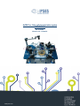
SoCRATes - Solar cell characterization system USER MANUAL Rel. 01.00.0001 (Hardware code: SoCRATes) 1 www.ipses.com SoCRATes USER MANUAL _____________________________ Information provided in this manual is property of IPSES S.r.l. and must be considered and treated as confidential. This publication can only be reproduced, transmitted, transcribed or translated into any human or computer language with the written consent of IPSES S.r.l. Information in this documentation has been carefully checked and is believed to be accurate as of the date of publication; however, no responsibility is assumed of inaccuracies. IPSES will not be liable for any consequential or incidental damages arising from reliance on the accuracy of this documentation. Information contained in this manual is subject to change without notice and does not represent a commitment on the part of IPSES. The design of this instrument is subject to continue development and improvement. Consequently, the equipment associated to this document may incorporate minor changes in detail from the information hereafter provided. All brand or product names are trademarks or registered trademarks of their respective holders. This manual in English is the original version. Printed in Italy Copyright 2009-2015IPSES S.r.l. All rights reserved. 2 IPSES S.r.l. Via Suor Lazzarotto, 10 - 20020 Cesate (MI) - ITALY Tel. (+39) 02 39449519 Fax (+39) 02 700403170 http://www.ipses.com e-mail [email protected] SoCRATes USER MANUAL GUARANTEE IPSES warrants to the end-user in accordance with the following provisions that its branded hardware products, purchased by the end-user from IPSES company or an authorized IPSES distributor will be free from defects in materials, workmanship and design affecting normal use, for a period of one year as of the original purchase date. Products for which proper claims are made will, at IPSES’s option, be repaired or replaced at IPSES’s expense1. Exclusions This Guarantee does not apply to defects resulting from: improper or inadequate installation, use or maintenance; actions or modifications by unauthorized third parties or the end-user; accidental or wilful damage or normal wear and tear. Making a claim Claims must be made by contacting IPSES office within the guarantee period. Please, contact: IPSES S.r.l. - Via Suor Lazzarotto, 10 - 20020 Cesate (MI) Italy Tel. (+39) 02 39449519 – (+39) 02 320629547 Fax (+39) 02 700403170 http://www.ipses.com - e-mail: [email protected] Limitation and Statutory Rights IPSES makes no other warranty, guarantee or like statement other than as explicitly stated above and this Guarantee is given in place of all other guarantees whatsoever, to the fullest extent permitted by law. In the absence of applicable legislation, this Guarantee will be the end-user’s sole and exclusive remedy against IPSES. General Provisions IPSES makes no express warranties or conditions beyond those stated in this warranty statement. IPSES disclaims all other warranties and conditions, express or implied, including without limitation implied warranties and conditions of merchantability and fitness for a particular purpose. IPSES’s responsibility for malfunctions and defects in hardware is limited to repair and replacement as set forth in this warranty statement. IPSES does not accept liability beyond the remedies set forth in this warranty statement or liability for incidental or consequential damages, including without limitation any liability for products not being available for use or for lost data or software. 1 With the exclusion of shipping costs for and from IPSES’s development office. 3 IPSES S.r.l. Via Suor Lazzarotto, 10 - 20020 Cesate (MI) - ITALY Tel. (+39) 02 39449519 Fax (+39) 02 700403170 http://www.ipses.com e-mail [email protected] SoCRATes USER MANUAL WARNING! ELECTRICAL DEVICES COULD DAMAGE EQUIPMENT OR PROPERTY OR CAUSE PERSONAL INJURY This guide contains instructions and technical features of SoCRATes - Solar cell characterization system. Read with attention before attempting to install. It is the responsibility of the technician to undertake all the safety rules provided by the law during the installation and the use of this device. For any information which is not contained in this guide, please contact: IPSES S.r.l. - Via Suor Lazzarotto, 10 - 20020 Cesate (MI) Italy Tel. (+39) 02 39449519 – (+39) 02 320629547 Fax (+39) 02 700403170 http://www.ipses.com - e-mail: [email protected] 4 IPSES S.r.l. Via Suor Lazzarotto, 10 - 20020 Cesate (MI) - ITALY Tel. (+39) 02 39449519 Fax (+39) 02 700403170 http://www.ipses.com e-mail [email protected] SoCRATes USER MANUAL TABLE OF CONTENTS USER MANUAL .............................................................................................................................................................. 1 TABLE OF CONTENTS .................................................................................................................................................. 5 REVISION HISTORY .......................................................................................................................................................... 6 MAIN SYSTEM COMPONENTS ......................................................................................................................................... 7 General features of the system ....................................................................................................................................... 7 Electrical features ........................................................................................................................................................... 9 Mechanical system ....................................................................................................................................................... 11 Wafer chuck .................................................................................................................................................................. 14 wafer alignment ............................................................................................................................................................ 17 Security lock of the system ........................................................................................................................................... 25 Software........................................................................................................................................................................ 26 Software installing .................................................................................................................................................... 27 Software Operation .................................................................................................................................................. 29 Control Unit ................................................................................................................................................................... 44 Connections .................................................................................................................................................................. 46 Technical Specifications ............................................................................................................................................... 48 CONTACTS ...................................................................................................................................................................... 49 SUPPORT INFORMATION ............................................................................................................................................... 50 PROBLEM REPORT......................................................................................................................................................... 50 ENGINEERING PROBLEM REPORT............................................................................................................................... 51 5 IPSES S.r.l. Via Suor Lazzarotto, 10 - 20020 Cesate (MI) - ITALY Tel. (+39) 02 39449519 Fax (+39) 02 700403170 http://www.ipses.com e-mail [email protected] SoCRATes USER MANUAL REVISION HISTORY Manual revision history Revision/ Date 01.00.0000 July 2014 01.00.0001 June, 2015 Change description Author First version Released Mancuso C. Update document layout Bottaccioli M. 6 IPSES S.r.l. Via Suor Lazzarotto, 10 - 20020 Cesate (MI) - ITALY Tel. (+39) 02 39449519 Fax (+39) 02 700403170 http://www.ipses.com e-mail [email protected] SoCRATes USER MANUAL SoCRATes is a test system aimed at measuring solar cells performance and repeatability by acquiring their voltage-current characteristic. The system is able to test and classify the cells contained in wafers of various sizes (up to 4 inches) and to interface with continuous light solar simulators, controlling the relevant shutter. MAIN SYSTEM COMPONENTS SoCRATes solar cell characterization system is composed of four main parts: 1. Active electronic load and I-V measurement unit, for the generation and measurement of electrical values on the solar cell under test; 2. A three-axes staging system, for the movement of the cells and for their contacting through test needles with micrometric adjustment; 3. An electronic unit for motion control of the staging system through the measurement management computer; 4. Quick and user-friendly software working in Windows environment for the management of the measurement For correct operation, the system needs to be complemented by other laboratory equipment, namely: A chiller for temperature stabilization of the water inside the wafer chuck; A rotary vacuum pump or a vacuum line; A solar simulator or appropriate light source, possibly with external control of the shutter. General features of the system SoCRATes consists of: An electronic unit with an active load able to generate the necessary signals to electrically excite the solar cell, then acquire the characteristic current-voltage curve (I-V) of the cell under test. This system allows the generation and acquisition of up to 1000 measurement points for each I-V curve; A Visible-NearInfraRed (NIR) camera imaging the cell under test for the evaluation of the electroluminescence in two ranges of emission wavelength, from 600 to 700 nm and from 800 to 1000 nm, respectively; A -temperature controlled vacuum chuck to support the solar cells wafer during the measurement, equipped with suction holes to keep the wafer in a steady position during the measurement. The temperature control and stabilization of the holderholder is achieved through water circulation operated by an external chiller A XYZ handling system to perform the automatic contacting of the pads of each cell on the wafer using the dedicated needles; A system consisting of 5 needles for the connection of the active load to the cell. Figure 1 shows the position of the 5 needles with their respective functions: o Force1 o Force2 o Sense1 o Sense2 o triple-junction cell diode (when applicable) Provision for an additional needle for future application is available on the system structure; Control software able to communicate and manage the system, provide the operator with a graphical interface to operate the system, and maintain a data base of measurement data.. 7 IPSES S.r.l. Via Suor Lazzarotto, 10 - 20020 Cesate (MI) - ITALY Tel. (+39) 02 39449519 Fax (+39) 02 700403170 http://www.ipses.com e-mail [email protected] SoCRATes USER MANUAL Space for optional support Diode tester Force 1 Sense 2 Force 2 Sense 1 Figure 1 –test needles 8 IPSES S.r.l. Via Suor Lazzarotto, 10 - 20020 Cesate (MI) - ITALY Tel. (+39) 02 39449519 Fax (+39) 02 700403170 http://www.ipses.com e-mail [email protected] SoCRATes USER MANUAL Electrical features The electronic active load and signal acquisition unit performs the digital conversion and processing of the following physical quantities: voltage through the Device Under Test (DUT) terminals between sense1+sense2 needles and the substrate; Sense1+Sense2 are connected together: the redundancy allows averaging out small voltage differences spatially distributed on the cell; current through the DUT between Force1+Force2 needles and the substrate; Force1+Force2 are connected together: the redundancy allows reduction of the cathode resistance and achieving a better current distribution on the cell during the measurement; voltage through the diode in the triple-junction cell between the diode needle and the substrate; current through the diode in the triple-junction cell between the diode needle and the substrate; temperature of the DUT, read by a sensor placed inside the temperature controlled DUT chuck. The analog to digital conversion is achieved using four independent 16 bit-converters. The signal acquisition sampling period ensures up to a 1,000 measurement points for the standard I-V characteristic curve of a normal solar cell with a fill factor greater than 0.83. Before starting the test, the operator defines the voltage or current increment step and the duration of each step. The total overall measurement time can reach few seconds/cell. The built-in electronic load is controlled by a 16 bit digital to analog converter that controls two independent power output stages. The selection on the output stage in use is automatically performed based on the current range defined by the operator for the measurement. The load can manage a maximum peak current of 15A, with a maximum voltage range of 10V. The first power output stage manages current up to 100 mA (either sink or source), while the second one up to 15 A peak (either sink or source). The electronic load operates therefore on all four quadrants of the I-V characteristic. It is then able to force the current into the DUT, both the direct one (e.g. for testing electroluminescence on solar cells both in P and N substrate), and the reverse one. Besides, it can force the voltage either positive and negative (for example, to allow DUT screening based on reverse current at a preset voltage, both for P- and N-substrate solar cells). The DUT is connected to the acquisition unit via six connection points: the pair of needles constituted by Force1 Force2 establishes the connection to one of the terminals of the electronic load, the Sense1 and Sense2 needles are used as the sense terminal of the voltage to be measured, and finally two cables (one for the second terminal of the electronic load and one for the second sense terminal) are connected to the substrate of the wafer through the bulk conducting mass of the wafer chuck. An optional further connection is available for a needle which can be used to contact the bypass diode protecting triple-junction solar cell. In case the voltage is forced on the DUT, the current measurement is performed by measuring the voltage drop across a precision low TC metal film resistor inserted in series to the DUT. A similar configuration allows the current measurement of the reference cell. The protection bypass diode in the triple-junction cells can also be characterized by forcing current and voltage. An embedded 32-bit microcontroller manages the entire unit according to parameters provided by the control computer using the measurement software. The system can perform autonomously the following measurement cycles: 1. Among "force" terminals and the wafer chuck: a voltage (up to a maximum of 10V between N and P of the cell) is applied, then the current delivered by the cell is read (the cell works in the first Cartesian quadrant and the maximum current must not exceed 15A) while the illumination enabled 2. Among "force" terminals and the wafer chuck: a reverse current is applied (up to a maximum of -1A) on a single junction cell, then the voltage is read while illumination is disabled. The cell works in the second Cartesian quadrant and the voltage must not exceed 10V, otherwise the test result will be "FAIL"; 3. Among "force" terminals and the wafer chuck: a direct current (up to a maximum of 2A) is applied on a single or triple junction cell while the illumination is disabled, then the voltage and the relevant electroluminescence image are acquired; 9 IPSES S.r.l. Via Suor Lazzarotto, 10 - 20020 Cesate (MI) - ITALY Tel. (+39) 02 39449519 Fax (+39) 02 700403170 http://www.ipses.com e-mail [email protected] SoCRATes USER MANUAL 4. Among "force" terminals and the wafer chuck: a reverse voltage (up to a maximum of -10V) is applied on a triple junction cell, then the current is acquired (the cell works in the fourth Cartesian quadrant); 5. Between the diode terminal and the wafer chuck: a reverse voltage (up to a maximum of -10V) is applied on the diode of a triple junction, then the current is read; 6. Between the diode terminal and the wafer chuck: a direct current is applied on the diode of a triple junction, then the voltage is read. The substrate of the wafer can be either P-type (typical of triple-junction cells), or N-type (typical of single-junction cells). Therefore during the measurement sessions the terminals will assume the following voltages, according the selected test: 1. A) for type-P substrate cells: Sense1+Sense2 with positive voltage in relation to the substrate; the current will go out from the upper side of the solar cell toward Force1+Force2, then it will go toward the substrate of the cell. B) for type-N substrate cells: Sense1+Sense2 with negative voltage in relation to the substrate; the current will go out from the substrate of the cell toward the wafer chuck, then toward Force1+Force2 and finally toward the upper side of the cell. 2. A) for type-P substrate cells: Sense1+Sense2 with negative voltage in relation to the substrate; the current will go out from the upper side of the solar cell toward Force1+Force2, then it will go toward the substrate of the cell. B) for type-N substrate cells: Sense1+Sense2 with positive voltage in relation to the substrate; the current will go out from the substrate of the cell toward the wafer chuck, then toward Force1+Force2 and finally toward the upper side of the cell. For both cases, the aim is to polarize the cells with direct voltage in order to measure the signal of electroluminescence; 3. A) for type-P substrate cells: Sense1+Sense2 with positive voltage in relation to the substrate; the current will go out from the substrate of the cell toward the wafer chuck, then toward Force1+Force2 and finally toward the upper side of the cell; B) for type-N substrate cells: Sense1+Sense2 with negative voltage in relation to the substrate: the current will go out from the upper side of the solar cell toward Force1+Force2, then it will go toward the substrate of the cell. 4. Fifth needle with negative voltage in relation to the substrate: the current will enter into the diode coming from the substrate, then it will go out from the fifth needle; 5. Fifth needle with positive voltage in relation to the substrate: the current will enter into the fifth needle coming from the upper side of the cell, then it will go out from the diode; While contacting the DUT, the system maintains both force terminals shorted with the wafer holder to prevent any risk to the cell due to extra voltages/currents. The system manages finally a switch SPDT relay used to control the shutter of the external solar simulator. 10 IPSES S.r.l. Via Suor Lazzarotto, 10 - 20020 Cesate (MI) - ITALY Tel. (+39) 02 39449519 Fax (+39) 02 700403170 http://www.ipses.com e-mail [email protected] SoCRATes USER MANUAL Mechanical system The dimensions of the mechanical unit of the instrument are 700 (W) x 600 (D) x 446 (H) mm. The unit should be placed on a stable surface with similar or larger dimensions. SoCRATes is equipped with three separate motor handling systems for X, Y and Z axes (Figure 2). X axis motor Z axis motor Y axis motor Figure 2 – Motors of the device (rear view) The panel on which the wafer chuck is located can move in the horizontal plane thanks to two motors providing respectively the movement on the X and Y axes. Each motor revolution corresponds to a displacement of 2 mm. The total range is ± 70 mm for the X axis and ± 55mm for the Y axis For the vertical Z axis the total range is 25 mm. The wafer chuck can be positioned at a height included between 240 up to 265 mm from the base of the system. Each motor revolution moves the table of 2 mm. The system is equipped with four adjustable feet; a bubble level on the front facilitates the correct levelling of the wafer chuck. Once the wafer is positioned and aligned (see page 17 - Alignment of the wafer), the operator is required to adjust manually every needle on the pads of the first cell of the wafer, using the three adjustment knobs (see Figure 3). The adjustment knobs allow the positioning of the needles to reach any point inside the cell. Each notch on the adjustment knob corresponds to a displacement of 0.01 mm. One revolution of the knob causes a displacement of 0.5 mm. The turrets have a range of 40 mm on the X and Y axes and of 20 mm in the Z axis. Once the needles are placed into the desired position, the turrets can be locked tightening the respective locking knobs (in Figure 3 the locking knobs for the X and Z axes are highlighted). The turrets are placed on a turntable which allows their angle adjustment. Their fastening is secured by Allen head screws. The clamp holding the needle arm allows you to adjust the angle and distance of the needle holder from the wafer. 11 IPSES S.r.l. Via Suor Lazzarotto, 10 - 20020 Cesate (MI) - ITALY Tel. (+39) 02 39449519 Fax (+39) 02 700403170 http://www.ipses.com e-mail [email protected] SoCRATes USER MANUAL Z axis locking knob for Z axis Y axis Rotation plate X axis adjustment knob X axis Figure 3 – Adjustment knobs for needle positioning A Bakelite fitting connects the needle holding head to the end of the arms (Figure 4). Both the head and the fitting are mobile to provide greater flexibility during the positioning of the needles. Figure 4 –needle holder arm and head Once the needles are properly positioned, the XYZ handling system will automatically move the wafer chuck to perform the test on each consecutive cell of the wafer under test. As the wafer is moved during the test sequence, each cell under test will be measured in the same position and with the same needle arrangement, reducing the risk of differences among the cells of the wafer in the illumination or in the electrical contacting during the test. 12 IPSES S.r.l. Via Suor Lazzarotto, 10 - 20020 Cesate (MI) - ITALY Tel. (+39) 02 39449519 Fax (+39) 02 700403170 http://www.ipses.com e-mail [email protected] SoCRATes USER MANUAL The wafer chuck plate movement is managed by the measurement software through the control PC. The precision of the movements of each axis is less than 100μm. He upper part of the unit provides an adjustable mounting fixture for the camera. 13 IPSES S.r.l. Via Suor Lazzarotto, 10 - 20020 Cesate (MI) - ITALY Tel. (+39) 02 39449519 Fax (+39) 02 700403170 http://www.ipses.com e-mail [email protected] SoCRATes USER MANUAL Wafer chuck The circular wafer chuck can be manually extracted to facilitate the loading and removal of the wafer placed on it (see Figure 5). Figure 5 – Position of the wafer chuck The wafer chuck (Figure 7) consists of two concentric stacked discs with 150 mm diameter for a total height of 20 mm. The bottom disc is made in plastic for thermal and electrical insulation, while the upper disc is in gold-plated copper. The plating has a nominal thickness of 0,15 μm, in order to ensure an optimal electrical and thermal connectivity and to prevent oxidation processes. ! Warning: During the use of the system, avoid use of metal tools that could scratch the gold-plated surface to avoid compromising the surface electrical and thermal properties, which may negatively affect the performance of the instrument. Four concentric grooves with a 10mm pitch are carved on the chuck top plate; the outermost groove has a diameter of 80mm. Within each groove there is a hole connected to an external vacuum system (Figure 6). The presence of several vacuum holes allows holding wafers of different sizes (up to a maximum diameter of 4 inches, or about 100 mm). The central vacuum hole, independent from the other 4 ones, is used for single cell measurements. Two plugs on the edge of the copper disc are used to connect the vacuum pump: The left plug is for the central hole (single cell), while the right plug connects to the other four holes (Figure 7). 14 IPSES S.r.l. Via Suor Lazzarotto, 10 - 20020 Cesate (MI) - ITALY Tel. (+39) 02 39449519 Fax (+39) 02 700403170 http://www.ipses.com e-mail [email protected] SoCRATes USER MANUAL concentric grooves and vacuum holes Figure 6 – Detail of the wafer chuck top plate surface Copper gold plated disc Vacuum connection for the 4 external holes Vacuum connection for central hole Water flow inlet (for chiller connection) Water flow outlet (for chiller connection) Plastic disc with heating control Figure 7 – wafer chuck The vacuum suction is controlled by two button valves located on the left side of the mechanical system (Figure 8). When the button valve is switched on, the suction is active, then, when the button valve is released the suction is interrupted and the room air connected, thus allowing the movement of the DUT. The front valve controls the aspiration of the central hole while the rear one manages the outer four holes. 15 IPSES S.r.l. Via Suor Lazzarotto, 10 - 20020 Cesate (MI) - ITALY Tel. (+39) 02 39449519 Fax (+39) 02 700403170 http://www.ipses.com e-mail [email protected] SoCRATes USER MANUAL Figure 8 – Button valves for operating the vacuum system on the wafer chuck. A further hole on the edge of the copper disc holds a 1.5 mm diameter PT100 for accurate measure of the wafer temperature during the test. The lower disc is made out of plastic material for electrical and thermal insulation and provides two plugs for the connection to a chiller. Through the inlet and outlet plugs (Figure 7) the water can flow inside the disc to maintain the wafer chuck temperature controlled, maintaining the DUT at a constant temperature during measure. The wafer chuck, then, performs four functions: electrical insulation toward mechanical structure firm positioning of the wafer or single cell thanks to suction holes (it requires an external vacuum pump or line); heating control through water flow inside the chuck (it requires an external chiller); electrical connection to the DUT substrate. 16 IPSES S.r.l. Via Suor Lazzarotto, 10 - 20020 Cesate (MI) - ITALY Tel. (+39) 02 39449519 Fax (+39) 02 700403170 http://www.ipses.com e-mail [email protected] SoCRATes USER MANUAL wafer alignment Before performing a test, the DUT must be aligned to the system. This procedure is especially critical when the test is performed on a wafer composed of multiple cells as the correct alignment of the wafer allows SoCRATes to perform the automated testing of all the cells of the wafer. The alignment procedure of the wafer is performed by aligning manually any test needle on the first and the last cell to be tested. First of all, it is necessary to allow SoCRATes control unit to know the position of the wafer holder with respect to the whole system: to do this, after connecting the PC to the control unit and launching the software, select the Home Position button on the main panel of the management software (Figure 9). This procedure should be performed only after the unit is power on: once the Home Position is acquired, the absolute position is maintained until the system shuts down. Any software restart does not cause the loss of data relating to the position and will not require repeating the alignment position. Figure 9 - Home Position Button The Home Position is defined as the median position between the X and Y axes of the system. The Home Position research cycle will first move all the axes toward the negative limit switch (to the left for the X axis, to the operator side for the Y axis and downward to the Z axis) and then moves to the median position. Once the Home Position is acquired, the operator can have access to the Set cell and wafer button, on the main panel of the management software. Pressing this button opens the Select cell to test window (see Figure 10), which contains the menu to set the cell parameters. 17 IPSES S.r.l. Via Suor Lazzarotto, 10 - 20020 Cesate (MI) - ITALY Tel. (+39) 02 39449519 Fax (+39) 02 700403170 http://www.ipses.com e-mail [email protected] SoCRATes USER MANUAL Figure 10 – Select cell to test window with the menu to set cell parameters In this menu, you must fill the fields Gross cell Xdimension (mm) and Gross cell Ydimension (mm) (surrounded in red in Figure 10). Choosing Select active cells form the drop down menu in the upper part of the Window (orange framed in Figure 10) the operator can compose the pattern of the wafer to be tested by selecting the the cells within the grid on the left. The cell parameter settings entered can be saved using the Save wafer CFG key and recalled using the Load wafer CFG button (green framed in Figure 10). Once the wafer configuration has been defined, the operator has to set the contact needles on the cell pads.. Move the wafer holder so that the first cell will be in the test position, simply pressing the Move to first cell key. Then start positioning a needle (for convenience, use the Force1 needle on the left) on the pad of the first cell to be tested. Position the needle by using the adjustment knobs on the needle holder turret (Figure 11). ! Warning: make sure that the needle is placed in a well identified position with respect to both axes, because it shall be placed in the same position on the pad of the last cell of the wafer. For instance, if you place the Force1 needle on the left upper corner of the first cell pad (see Figure 11), the needle must be placed on the left upper corner on the last cell pad too. Figure 11 – Alignment of a needle on the pad of the first cell of the wafer 18 IPSES S.r.l. Via Suor Lazzarotto, 10 - 20020 Cesate (MI) - ITALY Tel. (+39) 02 39449519 Fax (+39) 02 700403170 http://www.ipses.com e-mail [email protected] SoCRATes USER MANUAL Once the procedure for setting the needle in the correct position on the pad of the first cell is completed, get the last cell of the wafer in the test position by pressing the Move to last cell button. The needle position will need to be adjusted on the pad of the last cell. As the aim of this procedure is to have the cells in a perpendicular position with respect to the system, do not adjust the needle position by using the knobs on the turret, but first correct as necessary the angle of the wafer by using the angle adjustment knob of the wafer holder (Figure 12) till the required rotation of the cells is achieved. The angle adjustment system is equipped with a locking knob, too. Once the angle is adjusted, you can proceed with a fine adjustment using the knobs on the turret of the needle holder. Then go back to the first cell (Move to first cell key) to verify that the alignment of the needle on the first cell is still satisfactory and in case repeat the steps until the correct alignment is achieved.. locking knob angle adjustment knob Figure 12 – angle adjustment knob of the wafer chuck and locking knob The achievement of a perfect orthogonal calibration of the wafer is done through a process of progressive approximations: calibration procedures on the first and last cell must been repeated until the positions of the needle on their pads will be the same. Once the position is achieved you can lock it using the proper knobs respectively on the needle holder turret and on the wafer chuck. Figure 13 – Alignment of the needle on the pad of the last cell of the wafer 19 IPSES S.r.l. Via Suor Lazzarotto, 10 - 20020 Cesate (MI) - ITALY Tel. (+39) 02 39449519 Fax (+39) 02 700403170 http://www.ipses.com e-mail [email protected] SoCRATes USER MANUAL The software allows the definition of a x-y placement offset: once the wafer is perpendicular, it is not necessary to move the needle by knobs, because it will be possible to fine adjust the x-y position via software. Once the first needle is aligned with the pad of both first and last cell, it will possible to positioning the other required needles (Figure 14) in a very easy and fast way without concerns of the alignment already ensured by the perpendicular position of the wafer. Figure 14 – Alignment of 4 needles on the pads of the first cell of the wafer Through the drop-down menu located on the upper part of Select cell to test window (orange framed in figure 15) it is possible to select two modalities: Select active cell and Move to selected pos. Select active cell, as mentioned before, allows to select the active cells within the grid on the left in order to compose the pattern of the wafer to be tested. Move to selected pos function, allows you to select any cell inside the wafer, then the wafer chuck will move so to align that cell with the needles. By using this function it is possible to verify the correctness of the alignment of the needles with any cell within the grid and to perform a manual test on a specific cell. Figure 15: Select active cell and Move to selected pos modalities 20 IPSES S.r.l. Via Suor Lazzarotto, 10 - 20020 Cesate (MI) - ITALY Tel. (+39) 02 39449519 Fax (+39) 02 700403170 http://www.ipses.com e-mail [email protected] SoCRATes USER MANUAL Camera for electroluminescence image acquisition The acquisition of the electroluminescence image is achieved through a camera with visible and NIR (near infrared) sensitivity. The camera is standard delivered with a 25 mm lens and two interchangeable bandpass filters (Figures 16 and 17). Figure 16 – Camera 25mm less Dark Red Bandpass Filter Dark Red Bandpass Filter Figure 17 – Lens and badpass filters 21 IPSES S.r.l. Via Suor Lazzarotto, 10 - 20020 Cesate (MI) - ITALY Tel. (+39) 02 39449519 Fax (+39) 02 700403170 http://www.ipses.com e-mail [email protected] SoCRATes USER MANUAL The camera is mounted on an adjustable arm to control the field of view and image accurately the wafer (Figure 18). Optionally it is possible to mount a second arm for an additionalIR camera, if imaging with wavelengths higher than 1000 nm is required. camera Figure 18 – holder arm with camera mounted on The camera is connected to the PC using a USB cable. It features a resolution of 1280X1024 pixels. The camera spectral response is shown in the graph below (Figure 19). 22 IPSES S.r.l. Via Suor Lazzarotto, 10 - 20020 Cesate (MI) - ITALY Tel. (+39) 02 39449519 Fax (+39) 02 700403170 http://www.ipses.com e-mail [email protected] SoCRATes USER MANUAL Figure 19 – in violet curve of the spectral response of the camera When electroluminescence imaging of the DUT is required, mount the appropriate bandpass filter onto the lens selecting it between the two provided. The filter is mounted directly in front of the lens without the need of removing the lens from the camera body or the camera from the mounting bracket. The first filter is a dark red bandpass filter optimized for an acquisition of wavelengths between 600 and 700 nm (Figure 20). Typical Transmission is: Passes 635-690nm; Absorbs 200-630nm; Reflects 695-1100nm. This filter will block UV and shorter visible wavelengths but still pass all longer wavelengths. Figure 20 - dark red bandpass filter 23 IPSES S.r.l. Via Suor Lazzarotto, 10 - 20020 Cesate (MI) - ITALY Tel. (+39) 02 39449519 Fax (+39) 02 700403170 http://www.ipses.com e-mail [email protected] SoCRATes USER MANUAL The second one is an IR Bandpass Filter optimized for an acquisition of NIR wavelengths included between 800 and 1000 nm (Figure 21). Typical Transmission is: Passes IR 810-990nm; Absorbs 200-800nm; Reflects 1010nm and above. This filter significantly improves and maximizes contrast when working in the near infrared range. Figure 21 - NIR Bandpass Filter 24 IPSES S.r.l. Via Suor Lazzarotto, 10 - 20020 Cesate (MI) - ITALY Tel. (+39) 02 39449519 Fax (+39) 02 700403170 http://www.ipses.com e-mail [email protected] SoCRATes USER MANUAL Security lock of the system The mechanical system for moving the wafer chuck incorporates an optical barrier for safety purposes. The optical barrier is positioned on the front of the system (Figure 22) and prevents the operator accessing the area dedicated to the movement of the wafer chuck during the movement of the system. Therefore, once a test cycle has been initiated, the operator cannot work on the position of the solar cells, since this would interrupt the movements of the axes and the execution of the test.. When the safety barrier is triggered and the movements blocked, a red Error LED lights on the front panel of the control unit. Figure 22 – Security photocell. 25 IPSES S.r.l. Via Suor Lazzarotto, 10 - 20020 Cesate (MI) - ITALY Tel. (+39) 02 39449519 Fax (+39) 02 700403170 http://www.ipses.com e-mail [email protected] SoCRATes USER MANUAL Software The management software can run under Windows 7 and further versions (either 32 and 64 bit) and allows to: independently and completely manage the characterization of all the cells present on a silicon or germanium wafer once this is manually aligned; manage the manual test of a single cell; manage the handling of the wafer chuck; manage the shutter of the solar simulator and the current reading of the cell during calibration of the emitted beam; manage the electroluminescence image acquisition and save them; manage the saving, loading and graphical presentation of the data that can also be exported in CSV format (Comma Separated Values); define 15 quality classes and associate automatically each tested cell with the relevant class; produce a summary report for a range of cells, saving significant data in rows and columns; and, maintain backward compatibility with data saved by "SCT - Solar Cell Tester" produced by AEDI (code P11MK29150) software: it is therefore possible to open all of the measurements made with that system. 26 IPSES S.r.l. Via Suor Lazzarotto, 10 - 20020 Cesate (MI) - ITALY Tel. (+39) 02 39449519 Fax (+39) 02 700403170 http://www.ipses.com e-mail [email protected] SoCRATes USER MANUAL Software installing For proper operation of SoCRATes control system you must install the software and the drivers on the provided CD. The process of installation consists of three simple steps: driver installation for the camera interfacing; driver installation for control system interfacing; software installation to manage the control unit. The installation CD contains three folders in which the setup files are stored. The IPSES D2XX v2.08.24 directory contains the drivers to manage the control system. You must execute the proper file according to the operating system of the control computer in use: dpinst_amd64 for 64 bit systems or dpinst_x86 for 32 bit systems. The CAM Driver directory allows to install the camera drivers. Also in this case you must execute the appropriate file: Driver64bit - uEye64_42000 for 64 bit systems or Driver32bit - uEye32_42000 for 32 bit systems). The directory labeled as SoCRATes, finally, contains the install kit for the manager software. The software has been developed using National Instruments LabVIEW 2010. Setup will start the installer. In the Destination Directory Window (Figure 23) it is possible to select6 the installation target directory both for the SoCRATes application and the National Instruments runtime engine. Figure 23 – Destination Directory The Next button allows you to move forward to the summary window listing the products that will be installed on the PC (Figure 24). 27 IPSES S.r.l. Via Suor Lazzarotto, 10 - 20020 Cesate (MI) - ITALY Tel. (+39) 02 39449519 Fax (+39) 02 700403170 http://www.ipses.com e-mail [email protected] SoCRATes USER MANUAL Figure 24 – Summary of Installation windows By clicking again on Next button you will start the software installation (Figure 25). Figure 25 –software installation At the end of the process, press Finish. The installation is now successfully completed and the SoCRATes system can be run. ! Warning: for the proper operation of the system, you must install the management software and drivers for interfacing the electronic system, the motors and the camera. Failure to install one of the software and driver components will compromise the proper operation of the system. 28 IPSES S.r.l. Via Suor Lazzarotto, 10 - 20020 Cesate (MI) - ITALY Tel. (+39) 02 39449519 Fax (+39) 02 700403170 http://www.ipses.com e-mail [email protected] SoCRATes USER MANUAL Software Operation By clicking on the relevant icon SoCRATes software starts, then the main control panel opens. From this panel you can access all the functionalities of the device. (Figure 26). Figure 26 – Main control panel of the management software The Connect key (surrounded in red in Figure 26) starts the communication between the PC and the control unit. Once the communication is enabled, it is necessary, as already explained above, identify the position of the wafer chuck with respect to the system: this is performed by using the Home Position button (surrounded in green in Figure 26) and must be done only if the electronic system has just been switched on: it is not necessary to perform this operation when only the software is restarted. Setting the wafer size The Set cell and wafer button (available only after you perform the home position procedure) allows to access the parameter settings of the wafer (Figure 27). Figure 27 – Wafer setting menu 29 IPSES S.r.l. Via Suor Lazzarotto, 10 - 20020 Cesate (MI) - ITALY Tel. (+39) 02 39449519 Fax (+39) 02 700403170 http://www.ipses.com e-mail [email protected] SoCRATes USER MANUAL In the Dimension box, surrounded in red in Figure 27, wafer cell dimensions must be entered: Gross cell Xdimension (mm) represents the width of each cell on the X axis (with values from 2.5 mm to 50 mm); Gross cell Ydimension (mm) represents the width of each cell on the Y axis (with values from 2.5 mm to 50 mm); Net cell area (mm2) is the useful area of the wafer (where there is the photovoltaic junction). Load wafer CFG and Save wafer CFG buttons (surrounded in blue in Figure 27) allow to save the inserted setting and load the previously saved settings respectively. Movement box (surrounded in green in Figure 27) includes several commands for the wafer chuck displacement: Move to the first cell moves the wafer chuck so the first cell is aligned on the center of the system; Move to the last cell moves the wafer chuck so the first celli s aligned on the center of the system; Z to test position: moves the wafer chuck Z axis up on test position; Z down(3mm): moves the wafer chuck Z axis 3 mm down in order to facilitate the manual handling of the test needles. Through the drop-down menu located on the upper part of Select cell to test window (figure 27, surrounded in orange) it is possible to select two modalities: Select active cell and Move to selected pos. Select active cell allows to select the active cells within the grid on the left in order to compose the pattern of the wafer to be tested. Move to selected pos function, allows you to select any cell inside the wafer, then the wafer chuck will move so to align that cell with the needles. the Information box (surrounded in purple in Figure 27) shows the information about wafer chuck coordinates with respect to the home position (the center of the system), the total number of cells that compose the wafers and the gross size of the wafer itself (gross size refers to cell size plus pads dimensions). The grid of cells on the left, once the Select active cell mode is on (see above, surrounded in orange in Figure 27), is used to specify the actual shape of the wafer by selecting the cells to be tested. The selected cells will turn yellow, while the other ones will be dark green. If you want to test only a small number of cells within the wafer, you can select just the cells that you intend to test. CAM Acquire button shows the image taken with the camera, in order to facilitate manual placement of the needles. Figure 28 – Cam live acquire window CAM Acquire button opens a window (Figure 28) allowing the settings of the following image parameters: gain; exposition, freeze and save the image. 30 IPSES S.r.l. Via Suor Lazzarotto, 10 - 20020 Cesate (MI) - ITALY Tel. (+39) 02 39449519 Fax (+39) 02 700403170 http://www.ipses.com e-mail [email protected] SoCRATes USER MANUAL Test preparation Once the wafer size parameters are entered, the Start test button on the main menu is enabled. This button allows the access to setting menu for electrical test parameters (Figure 29). Figure 29 – Setting menu of the electrical parameters The Enable Test Sequence check box, surrounded in red in Figure 29, allows to select the execution of a unique test or a test sequence on the same solar cell. Once this box is checked, it is possible to select the number of tests to be executed on the same cell (up to a maximum of 5 tests) and select the types of tests within the sequence created in this way (Figure 30, surrounded in red). Figure 30 – Selection of a test sequence The Test Manager box (surrounded in green in Figure 29) allows to select the type of test to be executed. If the Enable Test Sequence check box has not been checked (so the creation of a test sequence is disabled), Test Manager box allows to select either the test type and the polarity of the substrate (Figure 31). 31 IPSES S.r.l. Via Suor Lazzarotto, 10 - 20020 Cesate (MI) - ITALY Tel. (+39) 02 39449519 Fax (+39) 02 700403170 http://www.ipses.com e-mail [email protected] SoCRATes USER MANUAL Figure 31 –Test Manager box for a single test: on the left the selection of the test type, on the right the selection of the substrate polarity. If the Enable Test Sequence check box has been checked (so the creation of a test sequence is enabled), from the Test manager box is possible to select the number of test to be modified and the polarity of the substrate (Figure 32). The test types to be executed in the sequence are selected into the Test Sequence box directly operating on the drop-down menu of the specific test. Figure 32– Test Manager box for a test sequence The Test Type drop-down menu (for a the specific test) and the drop-down menus in the test sequence allow the selection among one of the following tests: Illuminated cell: characterization of a cell illuminated by the solar simulator during its normal operations; Reverse cell (current control): test of an inversely polarized cell with respect to normal operation, with current control; Reverse cell (voltage control): test of an inversely polarized cell with respect to normal operation, with voltage control; Direct diode: test on the diode of the triple-junction cell with direct polarization; Reverse diode: test on the diode of the triple-junction cell with reverse polarization. The operation of each test is based on the generation of a voltage or current ramp (depending on the type of test set). The Substrate polarity drop-down menu allows to select the polarity of the cell substrate. In the Test Parameters box (Figure 29, surrounded in blue) it is possible to set the control values of the current/voltage ramp for the test. If you execute a test with voltage control, selectable parameters will be: dV: represents the step to increase the voltage of the ramp; dt: represents the duration of each step; Vmax: represents the maximum voltage value at which the ramp is terminated; Imax: represents the maximum current value, set as the maximum value of security, at which the test is terminated anyway. If you execute a test with current control, selectable parameters will be: dI: represents the step to increase the current of the ramp; dt: represents the duration of each step; Imax: represents the maximum current value at which the ramp is terminated; Vmax: represents the maximum voltage value, set as the maximum value of security, at which the test is terminated anyway. 32 IPSES S.r.l. Via Suor Lazzarotto, 10 - 20020 Cesate (MI) - ITALY Tel. (+39) 02 39449519 Fax (+39) 02 700403170 http://www.ipses.com e-mail [email protected] SoCRATes USER MANUAL In the right Hardware parameters (read only) box (surrounded in orange in Figure 29) displays the values automatically set by the system elaborating those written by the user: Controls mode: displays if the test is performed under voltage or current control. The type of control is defined according to the Test Type selection; Diode Test: the LED lights up if you have selected a test that requires the involvement of the diode in the triple-junction cell and thus the fifth probe of SoCRATes; dG: represents the increment of current/voltage value recalculated with reference to the polarity of the substrate; Ginit: represents the starting value of the current/voltage for the generation of the ramp; Gmax: represents the maximum of current/voltage value recalculated with reference to the polarity of the substrate; HW Lim: represents the limit of the current/voltage (according to the running test) beyond which the limiter hardware activates; Stop Value: represents the limit of current / voltage (according to the test running) after which the test is terminated; The Shutter LED lights up only when you have selected a test involving the use of the shutter (Illuminated cell). Load setup and Save setup buttons (surrounded in yellow in Figure 29) allow you to save the current values and to load previously saved settings. The Advanced setup key opens the window for changing manually the low-level hardware values (Figure 33). Figure 33 – Test Parameters Panel to set low level hardware settings Start test button starts the test, while Close button closes the window returning to the main menu (without starting the test). Test execution Once the wafer size is entered and the voltage/current values to be applied to the solar cell are set, the test can be executed. It will automatically run until all the selected cells will be tested or until the operator will stop it. During the test phase on the PC monitor Test progress window appears (Figure 34). 33 IPSES S.r.l. Via Suor Lazzarotto, 10 - 20020 Cesate (MI) - ITALY Tel. (+39) 02 39449519 Fax (+39) 02 700403170 http://www.ipses.com e-mail [email protected] SoCRATes USER MANUAL Figure 34 – test progress During the progress of the test, cells that give a positive result are colored in green. The one giving a negative results are colored in red. The ones still to be tested are yellow colored. The lower part of Test progress window (red framed in Figure 34) displays information about the position of the cell under test and the overall progress of the test. Revision of test results Once the test execution is completed, the View Test Result button on the main menu panel is enabled. This button allows displaying the summary of the test results (see Figure 35). Button for the display mode selection Figure 35 –Test result window The left side of the window shows the pattern of the tested wafer (red framed in Figure 35). The button below allows you choosing among three display modes View tested cell, Underline class, View all classes (see Figure 36): 34 IPSES S.r.l. Via Suor Lazzarotto, 10 - 20020 Cesate (MI) - ITALY Tel. (+39) 02 39449519 Fax (+39) 02 700403170 http://www.ipses.com e-mail [email protected] SoCRATes USER MANUAL Figure 36 –Selection of the display mode The selection of View tested cell allows displaying test summary results. Solar cells for which the test performed returned a positive result are highlighted in green, while those that were negative in red. It is possible to select any cell within the wafer (the selected cell turns white color) to view the graph associated with. The Show test n. menu (surrounded in red in Figure 36) allows to display the required test: the number of tests that can be selected depends on the number of tests set as test sequence and are shown just behind (surrounded in green in Figure 36). The kind displayed graph depends on the selected test. graph is displayed synthetically in the right part of the window, but you can examine it in detail by activating the zoom function, clicking on the same graph (Figure 37). Figure 37 – Detail of the graph of a tested cell The drop-down View menu to the right side of the graph, allows you to change the display type between 11 possible graphics: voltage as a function of current; voltage as a function of power; voltage as a function of temperature; voltage in function of the current of the reference cell; current as a function of voltage; current as a function of power; current as a function of temperature; DUT current as a function of the current of the reference cell; voltage in function of time; current in function of time; temperature as a function of time. 35 IPSES S.r.l. Via Suor Lazzarotto, 10 - 20020 Cesate (MI) - ITALY Tel. (+39) 02 39449519 Fax (+39) 02 700403170 http://www.ipses.com e-mail [email protected] SoCRATes USER MANUAL Smoothing and Remove smoothing buttons (placed in the lower part of the Zoom window surrounded in red in Figure 37) allow respectively to work on graph noise smoothing spikes and to remove all smoothing operation previously performed. The EXIT button allows to go back to Test result window. The selection of Underline class (Figure 36) allows highlighting in green the cells that correspond to a certain characterization class (Figure 38). Once this feature is enabled, you must select the type of class that you want to highlight and the relevant filtering and limit values. Figure 38 –Underline class dipslay The selection of View class display (Figure 36), finally, allows you to subdivide the tested cells in classes according the correspondence with the range of predefined values. The Edit class button opens the windows for setting the values of each class (Figure 39). It is possible to define up to a maximum of 15 classes. The cells can be divided into classes according to one of the following six parameters: 1) Load current; 2) Fill factor; 3) Isc; 4) Voc 5) Max power; 6) Efficiency. Figure 39– Defining the number of classes and their parameters 36 IPSES S.r.l. Via Suor Lazzarotto, 10 - 20020 Cesate (MI) - ITALY Tel. (+39) 02 39449519 Fax (+39) 02 700403170 http://www.ipses.com e-mail [email protected] SoCRATes USER MANUAL Once class parameters are defined, the software assigns to each cell the value of the corresponding class. The cells for which the test has returned a fail result will be marked with the char F (Figure 40). The sign "-" indicates the solar cells not yet tested (or not present), while the question mark (?) indicates a cell which has been tested, but that does not belong to any of the user-defined classes. Save single test Button Save all test (wafer) Button Figure 40 – Characterization of cells in classes The Save single test and Save all test (wafer) buttons (see Figure 40) allow to save the results for individual cells or for the entire wafer respectively. Image acquisition using the camera On main menu window there are two buttons that allow you to capture images taken by the camera integrated into SoCRATes system (see red- and green-framed buttons in figure 41). Test and archive command group Service command group Figure 41 – Main control panel of the management software: Cam acquire and Electroluminescence buttons 37 IPSES S.r.l. Via Suor Lazzarotto, 10 - 20020 Cesate (MI) - ITALY Tel. (+39) 02 39449519 Fax (+39) 02 700403170 http://www.ipses.com e-mail [email protected] SoCRATes USER MANUAL The CAM Acquire button is located within the Service command group. The selection of this function opens the real-time image acquisition window. This window can be accessed also form Set cell and wafer menu, as described above (pag 28). The Electroluminescence key (located within the Test and archive command group) allows opening the Electroluminescence window from which it is possible to visually assess the integrity of the semiconductor (Figure 42). Adjustment knobs for set current and voltage parameters Boxes to enter current and voltage parameters Figure 42 – Acquisition of an electroluminescence image of a cell In this window, you must set the appropriate current and voltage for the solar cell under test. These parameters can be set either through the regulation knobs, either by entering the values in the boxes below (see Figure 42). The Output Enable button enables the output of the power stage. If the values have been set correctly the cell will light up. It is important to put on the camera lens the appropriate filter according the type of wavelength emitted by the solar cell. The filter can be selected between the dark red bandpass one and the infrared bandpass one provided with. indicators of voltage (V), current (I) and temperature (T) of the CELL STATUS box display the values read back by the system. Manual test Selecting Manual Test button (purple-framed in Figure 41) on main menu it is possible to perform a manual test on a single solar cell. Clicking this key you open a window for setup electrical parameters to be applied to solar cell. This window has been already described above at pages 29-30. When you execute the manual test there is no handling of motors: needles should already be correctly positioned on the pads of the solar cell to be tested so to perform the test correctly. Once the manual test is finished, the window shown in Figure 43 appears. This window is very similar to the window for saving data for single solar cell. Here you can activate the zoom function of the graph and save the results. 38 IPSES S.r.l. Via Suor Lazzarotto, 10 - 20020 Cesate (MI) - ITALY Tel. (+39) 02 39449519 Fax (+39) 02 700403170 http://www.ipses.com e-mail [email protected] SoCRATes USER MANUAL Figure 43 –Result display of manual test The execution of a manual test on a solar cell is particularly suitable if you need to test a wafer composed of a unique cell or large size single cells. Managing saved files The Archive button of the main menu (surrounded in yellow in figure 41) allows accessing the ArchiveManager window. From this window, you can retrieve the previously saved results of the tests on a whole wafer or on a single solar cell (Figure 44). Figure 44 – Display results of a manual test From this menu you can reach the Test result window (described above). It is also possible to export the test data in CSV format (Figure 45). 39 IPSES S.r.l. Via Suor Lazzarotto, 10 - 20020 Cesate (MI) - ITALY Tel. (+39) 02 39449519 Fax (+39) 02 700403170 http://www.ipses.com e-mail [email protected] SoCRATes USER MANUAL Figure 45 – Result display in an Excel 2013 file Beam calibration The Beam calibration button on the main panel allows you to access the window for reviewing the electrical values of the cell for the manual calibration of the solar simulator. In this mode SoCRATes keeps short-circuit the DUT and reads the current delivered by it. The operator must set the value of a typical short-circuit current of the solar cell (ISC) in the Expected Current (A) box (Figure 46). If the current value proofread by SoCRATes exceeds by more than 10% of the value set by the operator, the system limits the circulating current and displays a warning message. The upper box shows the current value re-read by the system. The bottom box shows: the voltage values set by the system for the electronic load of the solar cell used to maintain at 0V the voltage across the cell (Intrernal voltage); rereading the actual voltage at the terminals of the solar cell (Read Voltage); the current value at which the hardware limitation of the current supplied by the solar cell triggers (it is equal to the value set by the operator increased by 10%); the temperature reread by the sensor placed inside the wafer chuck. This window is useful to correctly set the light intensity of the solar simulator (typically by varying the voltage applied to the lamp): using a reference cell whose short-circuit current is well renown (ISC), it is possible to adjusts the intensity of the beam light until the value read is the one expected. 40 IPSES S.r.l. Via Suor Lazzarotto, 10 - 20020 Cesate (MI) - ITALY Tel. (+39) 02 39449519 Fax (+39) 02 700403170 http://www.ipses.com e-mail [email protected] SoCRATes USER MANUAL Expected current box Figure 46 –Beam Calibration window Manual management of all low-level system functions The Service panel button on the main menu allows access to the setup menu of all the low level parameters of the system. ! Warning: the use of the capabilities of Service panel is indicated only for debugging the system in case of failure or malfunction. Normal operation of the system does not require access to this panel. Changing the low-level settings may affect the correct operation of the system and/or damage it. Change parameters in this panel only after contacting IPSES technical service. The Service panel window (Figure 47) is divided in three folders: System; Motors; Camera. folders Figure 47 – Service Panel window: System panel for introducing low-level electrical settings. The System panel window includes all the functionality for low-level electrical settings. Through the knobs or using the associated numerical controls, you can set the desired values of current and voltage. Channel Output allows to switch between Low power (fino a 0,1 A) and High power (da 0,1 A a 15 A) current. 41 IPSES S.r.l. Via Suor Lazzarotto, 10 - 20020 Cesate (MI) - ITALY Tel. (+39) 02 39449519 Fax (+39) 02 700403170 http://www.ipses.com e-mail [email protected] SoCRATes USER MANUAL Force Output selects the type of tests between Direct (using the terminal force) and Diode (that uses the terminal test diode). The Output Enable button activates the outputs of the selected power stage The box at the bottom allows you to monitor the system status and any error message that may occur. The System Status button allows to read the status of the SoCRATes control unit and to reset all error conditions. The Reset button causes the deactivation of ERROR indicator when lit. The ADC data box shows the reread values after the analog conversion: DUT V represents the voltage (between sense or test diode terminals and the ground, according the selection done with the force output button,); DUT I represents the current (between sense or test diode terminals and the ground, according the selection done with force output button); DUT T represents the measured temperature; DUT Ref I represents the measured current produced by a reference solar cell (if present). The Shutter button opens or closes the solar simulator shutter. The Calibration button allows to access setting calibration parameters of the device (Figure 48). Figure 48 – Calibration Panel From System panel window it is possible to start a test by entering test values and by pressing the Start Test. Test parameters can be set by pressing Test Parameters button, which leads to the Test Parameters panel, detailed above). The Motors panel window (Figure 49) allows manually moving the motors and setting their operating values such as speed, duration of the acceleration and deceleration ramps, and so on. 42 IPSES S.r.l. Via Suor Lazzarotto, 10 - 20020 Cesate (MI) - ITALY Tel. (+39) 02 39449519 Fax (+39) 02 700403170 http://www.ipses.com e-mail [email protected] SoCRATes USER MANUAL Figure 49 –Motors Panel Window The Camera panel window (Figure 50), allows capturing individual frames from the camera, and adjusting the exposure time and gain of the camera. Figure 50 – The Camera panel window Manual handling of the wafer chuck From the main menu it is possible to manually handle the wafer chuck by acting directly on the motors that move it, so as to bring the wafer chuck into three functional positions for test preparation stage. The Move out button lowers the wafer chuck, centers its position on the X axis, then move forward the chuck on the Y axis until reaching the end of stroke. This feature facilitates the removal and insertion of the cells to be tested on the chuck. The Central position button moves the wafer chuck to previously acquired home. The Down button moves the chuck of 3 mm downwards. 43 IPSES S.r.l. Via Suor Lazzarotto, 10 - 20020 Cesate (MI) - ITALY Tel. (+39) 02 39449519 Fax (+39) 02 700403170 http://www.ipses.com e-mail [email protected] SoCRATes USER MANUAL Control Unit The control unit includes the electronic active load for the signal generation required to handle the wafer chuck and the electric system for the actuation of the motors. On the front panel (Figure 51) there is the power button of the unit. Besides, indicator LEDs showing either the status of the system and of the DUT are present: Ready: indicates that the system is turned on and operating; Testing: indicates that the test on a solar cell is running; Error: indicates a system error occurred or the movement was stopped by the protection device (interlock); High Current: indicates that it is used the high current active load; Low Current: indicates that it is used the low current active load; Shorted: indicates the force terminals are contacting the wafer chuck. System Status DUT Status Ready High Current Testing Low Current Error Shorted Power Figure 51- Control Unit front panel On the rear panel (Figure 52) there are all the required connectors to interface the unit with the devices. A four-pin connector allows managing the shutter of the solar simulator. Its pin are connected according the following list: Connector on the Unit Pin 1 Pin 2 Pin 3 Pin 4 → → → → Provided cable normally open contact - GREEN central pole - BROWN system ground - BRAIDED SHIELD normally open contact - WHITE Shutter → → → Pin 1 Pin 5 Pin 2 The connector for the temperature probe is a three-pin one connected as listed below: Pin 1: sensor A; Pin 2: sensor B; Pin 3: system ground. The connector for the interlock is a five-pin one (within round brackets the colors of the wires of the cable provided with): 44 IPSES S.r.l. Via Suor Lazzarotto, 10 - 20020 Cesate (MI) - ITALY Tel. (+39) 02 39449519 Fax (+39) 02 700403170 http://www.ipses.com e-mail [email protected] SoCRATes USER MANUAL Pin 1: Positive (Green); Pin 2: Negative (Brown); Pin 3:Unused (White); Pin 4: Signal (Yellow); Pin 5: Unused (braided shield). The connector for the DUT is a ten-pin one (within round brackets the colors of the wires of the cable provided with): Pin A Force 1 (Red); Pin B Sense 1 and 2 (Blue); Pin C triple junction Sense diode (Blue); Pin D triple junction Force diode (Brown); Pin E System ground (yellow/green); Pin F Sense current of the reference cell (Red); Pin G Sense current of the reference cell (brown); Pin H Force 2 (Red); Pin I Sense GND wafer chuck (black); Pin J Force GND wafer chuck (black); On the rear panel there are also available: Power supply connection to the electricity net; Fan; USB interface for PC connection; Connector for motor control and limit switches; Auxiliary connector. Interlock Aux Shutter Temperature DUT Power supply USB Fan Motor control Figure 52 – Control Unit rear panel 45 IPSES S.r.l. Via Suor Lazzarotto, 10 - 20020 Cesate (MI) - ITALY Tel. (+39) 02 39449519 Fax (+39) 02 700403170 http://www.ipses.com e-mail [email protected] SoCRATes USER MANUAL Connections A connector box is present on the base of the mechanical system grouping all the interfaces.. On the front side of that box (Figure 53) there are all the connectors for plugging the resources of the mechanical system: Figure 53 –connections toward resources of the mechanical system The USB connector labeled with number 1 is the connection toward the camera. The round 32 pin connector labeled with number 2 connects all the signals coming from the motors, those of the limit switches, those of the PT100, those of the terminals of the reference cell, the chassis earth and system ground. The connectors labeled with number 3 are the inlet and outlet of the liquid for the temperature control of the wafer chuck (their connection to the wafer chuck is interchangeable because the direction of water flow makes no difference to the proper functioning of the system). The connector 4 is for the interlock connection. The plug 5 is for connecting the vacuum pipe to the wafer chuck. The connector labeled with number 6 is for the connection of the five test probes. The rear side of the box (Figure 54) has all the plugs to connect the mechanical system to the external devices, namely the control unit, the PC, the vacuum pump, and the chiller. 46 IPSES S.r.l. Via Suor Lazzarotto, 10 - 20020 Cesate (MI) - ITALY Tel. (+39) 02 39449519 Fax (+39) 02 700403170 http://www.ipses.com e-mail [email protected] SoCRATes USER MANUAL Figura 54 – Connections toward external devices The 25 pin connector (labeled as 1) is for motors and limit switches management. The 3-pin connector (n. 2) is for the connection of the temperature sensor. The circular 10-pin connector (n. 3) connects the control unit to the 5 test needles, to the terminals of the reference cell, to the chassis earth and system ground The USB connector (n. 4) is for connecting the camera directly to the PC. The plugs labeled as n. 5 are the inlet and outlet of the water from the chiller (the direction of water flow makes no difference). The n. 6 connector is for the vacuum pump. The n. 7 connector is for the interlock. 47 IPSES S.r.l. Via Suor Lazzarotto, 10 - 20020 Cesate (MI) - ITALY Tel. (+39) 02 39449519 Fax (+39) 02 700403170 http://www.ipses.com e-mail [email protected] SoCRATes USER MANUAL Technical Specifications 1 – Motorized sleds Axial displacement per motor revolution: 2 mm. total range X axis: 140 mm total range Y axis: 110 mm total range Z axis: 25 mm 2 – temperature measurement sensor: PT100 range: from 0° up to 80° C Tolerance Class: W0.3 (Class B) 3 – Camera interface: USB resolution: 1280 x 1024 focal length lens: 25mm wavelength dark red bandpass filter: 600 – 700 nm wavelength infrared bandpass filter: 800 – 1000 nm 4 – Probes and receptacles probe max range: 6,35 mm pressure force of the probe: typical 4N (with compression of 2,72 mm) receptacle diameter: 1,68 mm resistance: < 25 mΩ 5 – Generals Power supply: 230 Vac -50-60 Hz absorption max: 200W fuse: 5x20 – 1,5 A Fast Dimesions of SoCRATes mechanical unit: 700 (W) x 600(D) x 446(H) mm Dimesions of SoCRATes control unit: 510(W) x 470(D) x 200(H) mm 48 IPSES S.r.l. Via Suor Lazzarotto, 10 - 20020 Cesate (MI) - ITALY Tel. (+39) 02 39449519 Fax (+39) 02 700403170 http://www.ipses.com e-mail [email protected] SoCRATes USER MANUAL CONTACTS IPSES S.r.l. conceives, projects and markets electronic and scientific instruments. The customized planning of our devices allows us to answer specific necessities for customers asking for embedded systems. IPSES clients enjoy access to a dedicated project engineering team, available as needed. Our pool consists of highly competent professionals whose experience in this field is extremely strong. Thanks to constant updating and technical development, IPSES is a leading company, combining the dynamism of a young group into the competence and reliability of a qualified staff. IPSES S.r.l. Research and development office: Via Suor Lazzarotto, 10 20020 Cesate (MI) Italy tel. (+39) 02 39449519 - (+39) 02 320629547 fax (+39) 02 700403170 e-mail: [email protected] http://www.ipses.com 49 IPSES S.r.l. Via Suor Lazzarotto, 10 - 20020 Cesate (MI) - ITALY Tel. (+39) 02 39449519 Fax (+39) 02 700403170 http://www.ipses.com e-mail [email protected] SoCRATes USER MANUAL __________________________________ SUPPORT INFORMATION The customer is at liberty to contact the relevant engineer at IPSES S.r.l. directly. Telephone : Fax Email : : (+39) 02 39449519 (+39) 02 320629547 (+39) 02 700403170 [email protected] PROBLEM REPORT The next page is a standard template used for reporting system problems. It can be copied and send as a fax. Alternative bugs may be reported by emails, in this case please insure that the mail contains similar information listed in the Engineering Problem Report form. 50 IPSES S.r.l. Via Suor Lazzarotto, 10 - 20020 Cesate (MI) - ITALY Tel. (+39) 02 39449519 Fax (+39) 02 700403170 http://www.ipses.com e-mail [email protected] SoCRATes USER MANUAL ENGINEERING PROBLEM REPORT Problem describer Name Company Date Tel. Fax IPSES s.r.l. Via Suor Lazzarotto, 10 Cesate (MI) Italy Fax (+39) 02 700403170 e-mail [email protected] Product Name Version Serial No. Report Type (bug, change request or technical problem) Major bug Minor bug Change request Technical problem Urgency: High Medium Low Problem Description Reproduction of Problem IPSES s.r.l. Action notes Received by Date Report No. Action 51 IPSES S.r.l. Via Suor Lazzarotto, 10 - 20020 Cesate (MI) - ITALY Tel. (+39) 02 39449519 Fax (+39) 02 700403170 http://www.ipses.com e-mail [email protected] SoCRATes USER MANUAL (Product code SoCRATes Rel. 01.00.0001) IPSES S.r.l. Via Suor Lazzarotto, 10 20020 Cesate (MI) - ITALY Tel. (+39) 02 39449519 – (+39) 02 320629547 Fax (+39) 02 700403170 e-mail: [email protected] [email protected] 52 IPSES S.r.l. Via Suor Lazzarotto, 10 - 20020 Cesate (MI) - ITALY Tel. (+39) 02 39449519 Fax (+39) 02 700403170 http://www.ipses.com e-mail [email protected]