1
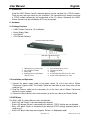
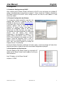
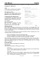
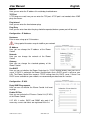
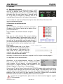
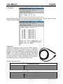
IPower Control 8
User Manual
English
LINDY No. 32652
www.LINDY.com
For Home and Office Use
Tested to Comply with
FCC Standards
© LINDY ELECTRONICS LIMITED & LINDY-ELEKTRONIK GMBH - FIRST EDITION (January 2011)
Contents
Safety Notice ........................................................................................................................ 3
1. Introduction ...................................................................................................................... 4
2. Hardware ......................................................................................................................... 4
2.1 Package Contents ....................................................................................................... 4
2.2 Installation and Operation ........................................................................................... 4
2.3 LED Status .................................................................................................................. 4
3. Configuration................................................................................................................... 5
3.1 Automatic Configuration by DHCP .............................................................................. 5
3.2 Newtwork Configuration by Software .......................................................................... 5
3.3 Configuration by Web Interface ................................................................................... 5
4. Operation ...................................................................................................................... 11
4.1 Operation of the device ............................................................................................. 11
4.2 Operation via the Web Interface ................................................................................ 11
4.3 Operation via the Serial Interface .............................................................................. 11
4.4 Sensor ....................................................................................................................... 12
5.
Features ....................................................................................................................... 13
5.1 Bootloader Mode ..................................................................................................... 133
5.2 Firmware Update ..................................................................................................... 133
5.3 Factory Reset .......................................................................................................... 133
5.4 Technical Data ........................................................................................................ 133
6. Support ......................................................................................................................... 14
User Manual
English
Safety Notice
This device must be only be installed and used by qualified personnel. The manufacturer
assumes no liability for improper use of the equipment, damage or injuries.
This device cannot be repaired by the customer and must only be performed by the
manufacturer. This device contains electrical parts with dangerously high voltages and must
not be opened or disassembled.
The power cables, plugs and sockets used with this device must be in good condition, whilst the
device must only be connected directly to a mains power outlet, with adequate grounding,
which provides power at 230 volts AC (50 or 60 Hz).
This equipment is intended for indoor use only. It should not be used in damp or excessively hot
areas. Please note the safety instructions in this manual. Please note also the safety and
operating instructions of the other equipment that are connected to the device.
This device is not a toy. It must not be kept or operated within the reach of children. Packaging
material can be dangerous, and must also be kept away from children.
LINDY IPower Control 8
www.LINDY.com
3
User Manual
English
1. Introduction
Using the LINDY IPower Control 8 electrical devices can be switched via a TCP/IP network.
There are only two steps necessary for installation: The connection to an electric circuit and
a TCP/IP network followed by the configuration of the IP settings. Afterwards the LINDY
IPower Control 8 can be switched by all PCs on the network.
2. Hardware
2.1 Package Contents
•
•
•
•
LINDY IPower Control for 19" Installations
Power Supply Cable
User Manual
CD-ROM with Software
Front view of the IPower Control
Rear view of the IPower Control
1.
2.
3.
4.
LED indicators for power ports
‘OK’ and ‘Select’ buttons
Status LED
Auxiliary port for serial adapter
cable or sensor
5.
6.
7.
8.
9.
Port for Temperature sensor
Network port (RJ45)
Display
8 Power Out Ports (IEC C13, max. 10A)
Power In Port (IEC C20, max. 16A)
2.2 Installation and Operation
1. Connect the power supply cable to the power socket (9) at the rear side of IPower
Control and a power outlet. The IPower Control will now boot up and shortly after will be
ready for use.
2. Plug the Ethernet cable into the connector (6) on the front side of IPower Control and
connect it to your network.
3. Connect the client devices to the active outlets (8) at the rear side of the IPower Control
2.2 LED Status
The Status LED (3) shows different states of the device:
• Status LED red: Device is not connected to the ethernet
• Status LED orange: Device is connected to the ethernet, TCP/IP settings are not allocated
• Status LED green: Device is connected to the ethernet,TCP/IP settings allocated, device is
ready to use
• Status LED blinks alternately red and green: Device is in Bootloader mode.
4
www.LINDY.com
LINDY IPower Control 8
User Manual
English
3. Configuration
3.1 Automatic Configuration by DHCP
After switching on the IPower Control it will look for a DHCP server and request an available IP
address (for deactivation of that feature on page 7). Please check the IP address allocated to
the IPower Control in the DHCP server settings to make sure that the same address is used
after every reboot.
3.2 Network Configuration by Software
To change the network properties manually, the
program GBL_Conf.exe is required. This tool is
available for free on our website www.lindy.com.
Furthermore GBL_Conf.exe enables you to install
firmware updates and to reset the IPower
Control to its factory settings (see page 14).
Activate the bootloader mode of the IPower
Control and run GBL_Conf.exe (see page 14).
The program will look automatically for connected
devices and will display their network
configuration. If the displayed IP address is the
factory setting (192.168.0.2), there is either no
DHCP server available in the network or no free IP
address could be allocated. Enter a free IP
address and the according netmask in the entry
mask, then save these changes by clicking on
Program Device > SaveConfig.
Restart the IPower Control by switching it off and on again, so that the changes will take effect.
Now click on Search in order to have the new network configuration displayed.
3.3 Configuration by Web Interface
Go to the website of the IPower Control, by entering the IP
address of the IPower Control into the address line of your
internet browser:
http://”IP address of the IPower Control”/
and press “LOGIN”.
LINDY IPower Control 8
www.LINDY.com
5
User Manual
English
To enter the configuration menu, click on “Configuration” on the upper left side of the screen.
Configuration - Power Ports
Label
A name with a maximum of 15 characters
can be entered here for each Power Port.
After power-up switch
The Power Port’s switching state after a
power-on of the IPower Control can be
defined here (on, off, remember last state).
If switching on after power-up, wait ...
A switching delay of a Power Port can be
defined here that is applied after switch on of
the IPower Control. The delay can last up to
8191 seconds.
After turning off, wait….
When this feature is activated, the Power
Port turns on automatically after a
predetermined time since it was disabled.
Watchdog Function
While using the Watchdog, electrical devices can be observed. The Watchdog sends ICMP
pings or TCP pings to the device. If these pings are not answered during a defined delay (time
or pings), the power port will reset. The Watchdog function allows you to restart (e.g. crashed)
servers or NAS systems.
You can check the Watchdog function and other information inside the switching menu. There
are different colours to let you know the status:
• Green text: Watchdog is active and receiving ping replies
• Orange text: Watchdog is activating at the moment, waiting for first ping reply
• Red text: Watchdog is active and does not receive ping replies any longer
When Watchdog is activating it waits for a first ping reply. During this time, the information is
written as an orange text. After the receipt of the first ping reply, it switches to active, written in
green letters. When Watchdog reset a power port, the Watchdog again waits for a first ping
reply, as stated above.
Enable Watchdog
Here you can activate the watchdog for this power port
Watchdog type
Here you can switch between ICMP ping and TCP ping
ICMP Pings:
Uses an Internet Control Message Protocol (ICMP) echo request to the network device,
such as a server or NAS to check access is possible.
TCP Pings:
Using a TCP Ping, you can check whether a specific service on the monitored network
device functions. So you can for example monitor TCP port 25 for a standard SMTP
server, TCP port 80 for a standard HTTP server, etc.
6
www.LINDY.com
LINDY IPower Control 8
User Manual
English
Host IP
Here you can enter the IP address this watchdog should observe
TCP Port
If TCP pings are used, here you can enter the TCP port. A TCP port is not needed, when ICMP
pings are chosen
Ping Interval
Here you can enter the time between pings
Ping Retry
Here you can enter how often the ping should be repeated, before a power port will be reset
Configuration - IP Address
Hostname
Enter a name using up to 15 characters
Using special characters may de-stabilise your network
IP Address
Here you can change the IP address of the IPower
Control
Netmask
Here you can change the netmask of the IPower
Control
Gateway
Here you can change the standard gateway of the
IPower Control
Use DHCP
Here you can set whether the IPower Control get its TCP/IP settings directly from your DHCP
server. If DHCP is activated, the IPower Control checks that a DHCP server is active on your
LAN. The IPower Control then requests TCP/IP settings from this DHCP server. If there is no
DHCP server available on your network, we recommend you deactivate this function.
Configuration - IP ACL
Reply ICMP-Ping requests
Here you can set whether the IPower Control shall react
on pings
Enable IP Filter
Here you can activate the IP Access Control List (IP ACL)
of the IPower Control.
If IP ACL is active, DHCP and SNMP only work if all
necessary servers and clients are registered in this list.
LINDY IPower Control 8
www.LINDY.com
7
User Manual
English
IP Access Control List
The IP Access Control List (ACL IP) is an IP filter for the IPower Control. When the filter is
active, only the hosts and subnets whose IP addresses are registered in the list can contact
the IPower Control to change settings and switch the power ports.
Example:
Entry in the IP ACL
192.168.0.123
192.168.0.1/24
Access
The PC with the IP Address 192.168.0.123 can access the
device
All devices on the subnet 192.168.0.1/24 can access the
device
If you are here locked out by mistake, select the bootloader mode of the IPower Control and
turn off the IP ACL using the GBL_Conf.exe.
Configuration – HTTP
HTTP Port
Here you can enter the HTTP port number, if
necessary. Possible numbers are 1 - 65534
(standard: 80). To get access to the IPower
Control, you have to enter the port number
behind the IP address of the IPower Control,
e.g.: http://192.168.0.2:1720
Enable HTML Auto Refresh
Here you can choose to auto-refresh the web
interface
Require HTTP Password
Password protected access can be activated
here. In this case, a user and an admin
password have to be defined. Passwords have
a maximum length of 15 characters.
Administrators are authorized to switch all ports and to modify the settings of the IPower Control
and of all ports. The username of the admin is “admin”. Users are authorized to switch all ports
but are not allowed to modify the settings of either the IPower Control or the ports. The
username of the user is “user”. If you have forgotten your password, activate the bootloader
mode of the IPower Control, start GBLConf.exe and deactivate the password request.
Check Password on start page
When this feature is activated the password is
checked before displaying the login page. This
prevents unauthorized persons from seeing the
switching status and the labels of the power ports.
Generate Messages
Here you can configure if and at which
Minimum/Maximum Temperature the IPower Control
shall send temperature alerts via SNMP Traps and
Syslog
8
www.LINDY.com
LINDY IPower Control 8
User Manual
English
Configuration - SNMP
Enable SNMPget
Here you can set whether the IPower Control should be
addressed over the SNMPget protocol.
Community public
Define the SNMP Working Group
Enable SNMPset
Here you can set whether the IPower Control should be
addressed over the SNMPset protocol.
Community private
Define the SNMP Working Group
Download SNMP MIB
Here you can download the MIB to query and control the IPower Control with SNMP
SNMP
You can use SNMP to get detailed status information from the IPower Control, via UDP (port
161). In addition you can use SNMP to switch the power ports. Supported SNMP commands:
• SNMPGET: Request status information
• SNMPGETNEXT: Request the next status information
• SNMPSET: Request change of status
You will need a Network Management System, e.g. HP-Open View, OpenNMS, Nagios etc.,
or the command line tools of NET-SNMP to request information of the IPower Control via
SNMP
SNMP Communities
SNMP authenticates requests by communities. The public community has to be added to
SNMP-read-requests and the private community to SNMP write requests. You can see the
SNMP communities like read/write passwords. SNMP v1 and v2 transmit the communities
without encryption. Therefore it is simple to spy out these communities. We recommend
using a DMZ or IP ACL.
MIB
All information, that can be requested or changed, “Managed Objects”, are described in
“Management Information Bases” (MIBs). There are three MIBs, which can be requested from
the IPower Control: “system”, “interface” and “powerports”. “system” and “interface” are
standardised MIBs (MIB-II). “powerports” was created especially for the IPower Control.
These three
sub-structures are called OIDs (Object Identifiers)
subordinate. An OID space
indicates the location of a value within the MIB tree. Each OID can alternatively be denoted
by its symbol name (name subtree).
SNMP Traps
SNMP Traps are system messages that are sent via the SNMP protocol to different
recipients. SNMP traps occur for the following events:
• Switching the power ports
• Exceeded max / min values of the sensors
For the available SNMP options see the section Configuration SNMP
LINDY IPower Control 8
www.LINDY.com
9
User Manual
English
Configuration - SNMP Trap Receiver List
Enable Traps
Here you can activate SNMP Traps. If enabled, the IPower
Control will dispatch SNMP Traps to all of the listed
recipients. Recipients have to be listed as follows: IP
address and, if necessary the HTTP port, e.g.:
192.168.0.2:8000
Trap Version
Here you can choose between SNMP v1 and v2c
standards for the type of SNMP Trap you want to send.
Configuration – Syslog
Enable Syslog
Here you can enable the Syslog function
Syslog Server IP
If Syslog is enabled, enter the IP address of your Syslog
server
Syslog Port
If Syslog is enabled, enter the port number that your
Syslog server uses to receive syslog information
Syslog
Syslog messages are simple text based messages transmitted to a syslog server using UDP.
Linux OS generally have a syslog daemon installed, e.g. syslog-ng. For Windows there are
freeware tools available.
On following events, the IPower Control will send a syslog message:
• Booting up
• Activation/deactivation of syslog
• Switching of Power Ports
10
www.LINDY.com
LINDY IPower Control 8
User Manual
English
4. Operation
4.1 Operation of the device
The IPower Control offers two buttons for control: “select”
and “ok”. By pushing “select”, the LED of Power Port 1
starts blinking which means that it is selected. By pushing
the button again, the next Power Port is selected, and so
on. If you want to change the switching state of the
selected Power Port, push the “ok” button for two seconds
You can check the status of the Power Ports by the colour of the Power Port status LED
(green=enabled/red=disabled)
4.2 Operation via the Web Interface
Switching
Go to the website of the IPower Control by entering the
IP address of the IPower Control into the address line of
your internet browser:
http://”IP address of the IPower Control”/ and press
LOGIN
Now you can switch directly. The current switching
state of the power ports is presented visually (red = off
/ on = green). In the lower part of the switching window,
you can see the current flow, and the peak current. If
you have connected a temperature sensor or a hybrid
sensor, you will see the sensor readings here as well.
Batchmode
Each individual power port of the IPower
Control can be set for a selectable period of
time (1-30 seconds or 1-30 minutes) in the
state "switch on" or "switch off". After the
selected time period it will automatically
switch to the predetermined condition.
Alternately, the device can be switched as required via a Perl script or external programs.
4.3 Operation via the Serial Interface
Alternatively to the ethernet/network interface, the Power
Ports of the IPower Control can be switched through its
serial interface. It only requires a terminal program like
HyperTerminal, a program provided under Windows for free
(found in Programs > Accessories > Communication).
Connect your PC to the IPower Control with the PS2-RS232 adaptor cable and plug the device
into a power outlet. Now you can turn on the IPower Control. The boot process takes a few
seconds longer than by Ethernet. You can access the IPower Control through the terminal
program as soon as the status LED lights up green. Choose the COM port that is connected to
the IPower Control and enter the following values for the serial interface:
If you do not use HyperTerminal, please make sure that the terminal program supports
VT100 commands.
LINDY IPower Control 8
www.LINDY.com
11
User Manual
English
After connecting successfully, the IPower Control answers as shown in figure below. Press
Enter to login.
Now the Power Ports can be switched on and off by number keys. By pressing “c” you can
check the network configuration and by pressing Esc you can log out.
4.4 Sensor
Connect the temperature sensor with the TEMP and AUX
connector at the front of the device. Once it is connected
correctly, the recent temperature is displayed in the login
window, in the switching window and can be requested via
SNMP. The sensors (temperature sensor, and hybrid
sensor for temperature and humidity) can be purchased as
an accessory from us. More information can be found at
www.lindy.com or you can contact our sales team.
Technical Data for Sensors:
Cable Length
Connector
Measurement
Cable Length
Connector
Measurement
12
Temperature Sensor
2m
PS/2
-10°C to +70°C at ±2°C (maximal) and ±1°C (typical)
Temperature/Humidity (Hybrid) Sensor
2m
PS/2
-40°C to +80°C at ±0,5°C , 0 – 100% ±3%
www.LINDY.com
LINDY IPower Control 8
User Manual
English
5. Features
5.1 Bootloader Mode
To activate the bootloader mode of the IPower Control press the “select” button while
restarting the device. In bootloader mode it is possible to disable password protection, to
update the firmware and to restore the default settings by running the program
GBL_Conf.exe. If the device runs already, press and hold the "select" and "ok" buttons for
three seconds. The bootloader mode of the IPower Control is indicated by “BOOT-LDR”
appended to the device name in the program window of GBL_Conf.exe. To restart the firmware,
without toggling the Power Ports, press and hold the "select" and "ok" buttons for three
seconds again.
5.2 Firmware Update
In order to update the firmware GBL_Conf.exe and the latest firmware are needed.
Start the device in bootloader mode and run the program GBL_Conf.exe. On the left side of the
program window all IPower Control devices that are in the network are listed. Select the device,
that should be updated, click on Program Device Firmware
Update and specify the location of the new firmware. Please note that the current version of the
firmware and the program GBL_Conf.exe are available for download from www.lindy.com
5.3 Factory Reset
You can roll back the IPower Control to Factory Default settings at any time using the software
GBL_Conf.exe. To complete the reset, and therefore delete all the settings you have entered,
please take the following steps:
• Enable the boot loader mode of the device
• Select the device in the software GBL_Conf.exe
• Select: Program Device - Reset Settings to Fab
• Disable now the boot loader mode
5.4 Technical Data
Connections:
Network:
Protocols:
Switched Power (total):
Switched Power (per port):
Power supply:
Operating temperature:
Dimensions:
Total weight:
1 x Ethernet (RJ45)
2 x PS2 Connector
8 x Power Ports (IEC C13, max. 10A)
1 x Power supply inlet (IEC C20, max. 16A)
10/100 MBit/s 10baseT Ethernet
TCP/IP, HTTP,
SNMP v1 und v2c, SNMP traps, Syslog
16 A (~ 3600W)
10 A (~ 2000W)
IEC C20 (16A, 230V AC)
0°C-50°C
19’’ / 1 rack unit
1.5 kg
The device can operate at 10Mbps or 100Mbps. By default from the factory it is set to 10Mbps.
It is recommended that you only change this setting if your network requires it. There is no
noticeable performance advantage in switching from 10Mbps to 100Mbps, as amount of data
transferred by the device is very small. By setting the IPower Control to 100Mbps it will use
more power and operate at a higher temperature.
LINDY IPower Control 8
www.LINDY.com
13
User Manual
English
6. Support
On our website, www.lindy.com you have the latest software on our products for free download.
For further questions about installation or operation of the IPower Control please contact our
support team.
14
www.LINDY.com
LINDY IPower Control 8
User Manual
LINDY IPower Control 8
English
www.LINDY.com
15
User Manual
English
CE Certification
This equipment complies with the requirements relating to electromagnetic compatibility, EN55022/EN55024 class B for
IEC/EN61000-4-2/3 the essential protection requirement of Council Directive 89/336/EEC on the approximation of the laws of
the Member States relating to electromagnetic compatibility.
FCC Certification
This equipment has been tested and found to comply with the limits for a Class B digital device, pursuant to part 15 of the FCC
Rules. These limits are designed to provide reasonable protection against harmful interference in a residential installation.
This equipment generates, uses, and can radiate radio frequency energy and, if not installed and used in accordance with the
instructions, may cause harmful interference to radio communications. However, there is no guarantee that interference will not
occur in a particular installation. If this equipment does cause harmful interference to radio or television reception, which can be
determined by turning the equipment off and on, the user is encouraged to try to correct the interference by one or more of the
following measures:
•
Reorient or relocate the receiving antenna
•
Increase the separation between the equipment and receiver
•
Connect the equipment into an outlet on a circuit different from that to which the receiver is connected
•
Consult the dealer or an experienced technician for help
You are cautioned that changes or modification not expressly approved by the party responsible for compliance could void your
authority to operate the equipment.
This device complies with part 15 of the FCC Rules.
Operation is subject to the following two conditions:
1.
This device may not cause harmful interference, and
2.
This device must accept any interference received, including interference that may cause undesired operation.
WEEE (Waste of Electrical and Electronic Equipment),
Recycling of Electronic Products
United Kingdom
In 2006 the European Union introduced regulations (WEEE) for the collection and recycling of all waste electrical and electronic
equipment. It is no longer allowable to simply throw away electrical and electronic equipment. Instead, these products must
enter the recycling process.
Each individual EU member state has implemented the WEEE regulations into national law in slightly different ways. Please
follow your national law when you want to dispose of any electrical or electronic products. More details can be obtained from
your national WEEE recycling agency.
Germany
Die Europäische Union hat mit der WEEE Direktive umfassende Regelungen für die Verschrottung und das Recycling von
Elektro- und Elektronikprodukten geschaffen. Diese wurden von der Bundesregierung im Elektro- und Elektronikgerätegesetz –
ElektroG in deutsches Recht umgesetzt. Dieses Gesetz verbietet vom 24.März 2006 an das Entsorgen von entsprechenden,
auch alten, Elektro- und Elektronikgeräten über die Hausmülltonne! Diese Geräte müssen den lokalen Sammelsystemen bzw.
örtlichen Sammelstellen zugeführt werden! Dort werden sie kostenlos entgegen genommen. Die Kosten für den weiteren
Recyclingprozess übernimmt die Gesamtheit der Gerätehersteller.
France
En 2006, l'union Européenne a introduit la nouvelle réglementation (DEEE) pour le recyclage de tout équipement électrique et
électronique.
Chaque Etat membre de l’ Union Européenne a mis en application la nouvelle réglementation DEEE de manières légèrement
différentes. Veuillez suivre le décret d’application correspondant à l’élimination des déchets électriques ou électroniques de
votre pays.
Italy
Nel 2006 l’unione europea ha introdotto regolamentazioni (WEEE) per la raccolta e il riciclo di apparecchi elettrici ed elettronici.
Non è più consentito semplicemente gettare queste apparecchiature, devono essere riciclate. Ogni stato membro dell’ EU ha
tramutato le direttive WEEE in leggi statali in varie misure. Fare riferimento alle leggi del proprio Stato quando si dispone di un
apparecchio elettrico o elettronico.
Per ulteriori dettagli fare riferimento alla direttiva WEEE sul riciclaggio del proprio Stato.
LINDY No. 32652
1st Edition January 2011
www.lindy.com
16
www.LINDY.com
LINDY IPower Control 8