1
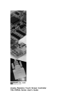
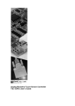
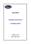
Analog Capacitive Touch Screen Controller Board
CSC-10/USB, RSA4, 5 Setup and User’s Guide
CSC-10/Controller User’s Guide
Table of Contents
1
1. Product appearance
1-1 Dimension
1-2 Static Protection Warning
1-3 Product Description
1-4 Product Number
1-5 Firmware Revision
1-6 Electrical Specification
1-7 Important Document and User Information
2
2
2
2
2
3
3
2 Set up Controller
2-1 Mounting the CSC Controller
Setup Diagram
2-2 Mounting the Capacitive Touch Screen
2-3 Connecting the Touch Screen
2-4 For best performance mount the controller
4
4
4
5
5
3 Connecting the CSC controller
3-1 Communication Protocol
Standard USB Protocol
Standard RS232 Protocol (4byte)
3-2 Status LED Indicator
3-3 Software and Device Drivers
5
5
6
6
6
4 MODIFICATIONS&IMPROVEMENTS
7
5 Warranty
5-1 Warranty Period
5-2 Warranty Target
5-3 Warranty Exceptions
8
8
8
6 PRECAUTIONS FOR USE
6-1 General cautions
6-2 Others
9
9
1
Rev.1.2 © 2008 DMC Co., Ltd.
CSC-10/Controller User’s Guide
Product appearance
1-1 Dimension
RS-232 Communication
USB Communication
CSC-10/RSA4
RS232 - 4Byte
CSC-10/USB
USB
CSC-10/RSA5
RS232 - 5Byte
NOTE: The controller board revision can be found on a label on the back side of your controller board.
The firmware revision may be found on a label or a laser mark located on the microcontroller chip.
1-2 Static Protection Warning:
The CSC controller has internal static protection to +/- 27kV for static discharge from the
touch screen to the controller. This static protection is only effective once the board is
grounded properly. Adequate static precautions must be taken when connecting the CSC
controller to your application. In some applications, it may be necessary to further protect
your controller board from excess transient voltage. Failure to take the necessary
precautions may result in damage to your controller. The board for static voltage
damage is not included in this warranty policy.
1-3 Product Description:
The CSC controller board is a standard capacitive touch screen controller, which supports
Serial and USB communication as well as all DMC capacitive touch screens with or
without back shield.
1-4 Product Number
CSC-10/RSA4:
RS232 - 4Byte, CSC-10/RSA5: RS232 - 5Byte, CSC-10/USB: USB
1-5 Firmware Revision
The latest firmware revision will be supplied with all CSC controller boards ordered.
2
Rev.1.2 © 2008 DMC Co., Ltd.
CSC-10/Controller User’s Guide
1-6 Electrical Specifications:
Touch Screen
Transmission Speed
Communication
Drivers
Power Options
Connector Options
Voltage Regulation
Power Consumption
Resolution
Board Size
Clock Frequency
Baud Rate
Data Output
Environmental
Static Protection
: All DMC Capacitive touch screens with or without back shield.
: 40 – 100 points/sec. (raw data 240 points/sec.)
: RS-232 or USB
: DOS, Win9x, ME, XP, NT, 2K, CE, NET, MAC, Linux,
: 5v – 16vDC or from USB port
: S4B-EH (JST)
on the controller board (RS-232, USB)
: S2B-EH (JST)
on the controller board (RS-232 only)
: SHE-001-P0.6 (JST) on a recommended communication cable
: EHR-4(JST)
(RS-232, USB)
: EHR-2(JST)
on a recommended communication cable
(RS-232 only)
: 5v – 16vDC
: 45mA (typical), 120mA (Max)
: 10-Bit (1,024 X 1.024)
: 66.5mm X 36.0mm
: 16 MHz
: 9600 baud (others available upon request)
: RS-232: 4 and 5 Byte, USB: 5 Byte
: Storage: -40c – 85c Operating: 0c – 70c
: 15kv – 27kv
1-7 IMPORTANT DOCUMENT AND USER INFORMATION
The CSC Series Capacitive Touch Screen Controller is manufactured and sold by DMC
Co., Ltd under a licensing agreement with Hampshire Company.
This document is to be used as a guide only. The information contained in this document
is subject to change without notice.
Due to the vast range of application variables that fall outside of DMC’s expertise and
control, DMC assumes no responsibility for the usability or suitability of CSC controller in
any medical, aviation, military or other life critical applications as well as customer
designed applications.
The DMC standard software products, including but not limited to device driver software,
are provided “as is” and may be used exclusively with an authentic CSC touch screen
controller.
3
Rev.1.2 © 2008 DMC Co., Ltd.
CSC-10/Controller User’s Guide
2 Set Up Controller
2-1 Mounting the CSC Controller
The controller has two 3mm-diameter plated mounting holes. Notice the mounting hole
closest to the touch screen connector H4. THIS STATIC GROUND MOUNT MUST BE
TERMINATED TO A STATIC GROUND. Failure to ground the controller will result in
poor performance and may eliminate the effectiveness of the board static protection.
See the Setup Diagram.
2-2 Mounting the Capacitive Touch Screen
Create appropriate clearance between an LCD display and a screen panel.
The CSC controller collects an environment baseline when powered on. Take special
care to mount the touch screen in such a manner as to eliminate any screen shift or
movement during operation.
4
Rev.1.2 © 2008 DMC Co., Ltd.
CSC-10/Controller User’s Guide
2-3 Connecting the Touch Screen
The CSC capacitive controller supports back shielded, non-back shielded and shielded
tail capacitive touch screen overlays. Check the touch screen tail and verify the pin-out
of the touch screen before connecting the touch screen to the controller. If the touch
screen has a back shield or a shielded tail, a connection must be made to the 3rd pin of
header H4. Failure to connect a shielded touch screen or tail will cause the controller to
malfunction. CSC capacitive touch screen controller can be connected to all DMC
capacitive touch screens directly.
2-4 For best performance mount the controller:
1) Away from high power, EMI and RFI components.
2) In such a way to keep the touch screen tail away from high EMI, RFI and power
sources.
3) In a way to insure that you are using a communication cable with adequate shielding
which is located away from high EMI, RFI radiating system components.
4) To shield the controller and/or the touch screen from EMI/RFI noise in cases where
required. Mounting the controller into a metal box which is shielded might be
necessary.
5) 5VDC – 16VDC power is required to power the CSC Capacitive controller board with
current up to 120mA. Before you power on your CSC controller, check the ground
termination and your power supply to insure proper configuration. The static ground
must be terminated to a static ground before powering on your controller board.
Failure to follow this procedure will bypass the static protection and may damage your
controller and the board may not function properly. See the mechanical/mounting
diagram.
3. Communications with the CSC Controller
The CSC capacitive touch screen controller supports RS-232 and USB (HID compliant,
low speed) communication. While these are DMC’s standard communication formats,
custom communications are available.
The standard controller will dynamically report 40 ->100 verified touch points per second.
These are verified, tested points and are determined by the action of the activator.
3-1 Communication Protocol
Standard USB Protocol
Byte
Bit7
Bit6
1
0
0
2
X7
X6
3
0
0
4
Y7
Y6
5
0
0
Bit5
0
X5
0
Y5
0
Bit4
0
X4
0
Y4
0
Bit3
0
X3
X11
Y3
Y11
5
Bit2
0
X2
X10
Y2
Y10
Bit1
0
X1
X9
Y1
Y9
Bit0
P
X0
X8
Y0
Y8
Rev.1.2 © 2008 DMC Co., Ltd.
CSC-10/Controller User’s Guide
Standard RS-232 Protocol (4 byte)
Byte
Bit7
Bit6
Bit5
1
1
P
X11
2
0
X8
X7
3
0
Y8
Y7
4
0
0
0
Bit4
X10
X6
Y6
0
Bit3
X9
X5
Y5
X1
Bit2
Y11
X4
Y4
X0
Bit1
Y10
X3
Y3
Y1
Bit0
Y9
X2
Y2
Y0
Where P 0 pen-up, 1 pen-down
X11-X0
12 bit X position data
Y11-Y0
12 bit Y position data
PU
0 no pen-up, 1 pen-up
PD
0 no pen-down, 1 pen-down
CK-CK0 – AAH + 55H + Sum of Bytes 2 through 9
3-2 Status LED Indicator
The CSC capacitive controller board is equipped with a status-indicator Light Emitting
Diode (LED). This LED will give you information regarding the functionality of the
controller. The LED indication codes are as follows:
When powered on: The LED blinks in a moment.
Every time the touch screen is touched: It will turn on every time the operator touches the
touch screen.
3-3 Software and Device Drivers
Note: The touch screen must be calibrated using the calibration software utility before the
touch screen will properly function.
The CSC controller is currently supported by DCD-UniWinDriver (Win98se, WinXP, Win2k).
The drivers are also available for DOS, Windows 3.11, NT, ME, XPe, Windows CE, Linux
WindRiver.
Please review the driver user’s manual for instruction for installing the driver.
6
Rev.1.2 © 2008 DMC Co., Ltd.
CSC-10/Controller User’s Guide
4 MODIFICATIONS & IMPROVEMENTS
Version History
Rev1.0 (December.15.2007)
Rev1.1 (December.21.2007)
Rev1.2 (August.12.2008)
First Edition
Connector parts number changes
The board dimensions are revised
7
Rev.1.2 © 2008 DMC Co., Ltd.
CSC-10/Controller User’s Guide
5 Warranty
5-1 Warranty Period
§ The warranty period is limited to 1 year from the date of shipping. The warranty for the
initial defection such as appearance defection is limited to 1 month.
§ Any defected parts under proper use will be examined by the supplier and replaced by
the new parts if the defection is considered to be caused by the supplier.
§ The replacement is subject to be included in the next lot.
5-2 Warranty Target
§ The warranty only covers the product itself and does not cover any damage to others
caused by using this product. Onsite repair or replacement is not supported.
§ We will do our best for delivery problem and product defections but the warranty for the
production line is not covered.
5-3 Warranty Exceptions
Following conditions are not covered with the warranty and subject to charge.
§ Any malfunctions and damages during transportation and transfer by the user.
§ Any malfunctions and damages caused by a natural disaster or a fire.
§ Any malfunctions and damages caused by static electricity.
§ Any malfunctions and damages caused by the failure of the associated equipment.
§ If the product is remodeled, disassembled or repaired by the user.
§ If the product is glued onto the equipment and uninstalled.
§ Any malfunctions and damages caused by an improper usage and handling against the
specifications and notes.
8
Rev.1.2 © 2008 DMC Co., Ltd.
CSC-10/Controller User’s Guide
6 PRECAUTIONS FOR USE
6-1 General cautions
§ Do not place any conductive materials closer to CSC series.
§ Do not touch any metal parts of CSC series as it may be damaged by static electricity.
Use antistatic table in case of touching it by hand.
§ Keep CSC series in a carton box without any other abnormal loading pressure under
storage temperature and humidity environments as below:
Wet (or may wet) environments
Condensation (or likely to occur condensation)
Organic solvent or acidic substance environments
§ Re-modeling or disassemble is your own risk.
6-2 Others
§ This specification is subject to change for improvements without prior notice.
§ DMC is not responsible for any damage or loss caused by use of CSC series.
§ CSC series are designed for general purpose (such as office use , industrial machines,
communication equipments and home appliances). It should NOT be used for the
application where any irregular operation may harm or damage to human or any special
purposes which require higher reliability such as medical, aerospace and equipment.
§ Please pay careful attention to safety guard when designing your products to avoid
accidental death, fire or any social damages.
CSC Controller User’s Guide
Rev 1.1 December 21,2007
© 2007 DMC Co., Ltd.
Reprint of this user guide may be permitted upon request but not allowed to revise this user guide.
DMC Co., Ltd. Tokyo office
http://www.dmccoltd.com
9thfloor, Kanda Sento Building, 1-2-4 Yushima, Bunkyo-ku, Tokyo 113-0034, Japan
Phone : +81-3-5209-7131(Japanese),7135(English) Fax : +81-3-5209-7130
9
Rev.1.2 © 2008 DMC Co., Ltd.