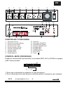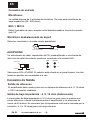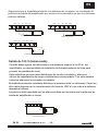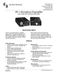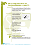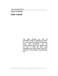
1
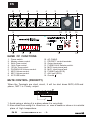
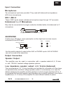
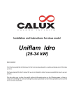
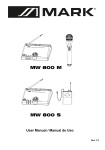
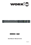
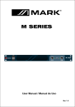
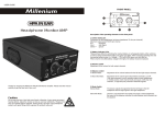
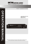
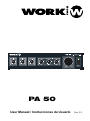
PA 50
User Manual / Instrucciones de Usuario
Rev. 2.0
EN
GENERAL DESCRIPTION:
For greater operational flexibility, two Microphones can be inserted in the amplifier,
on which also have "AUX" inputs, which can provide for the use od radio tuner, CD
player and other high impedance high power input.
“MIC", "AUX", "PHONO" positions are all set on volume controllers, which can
freely adjust the volume needed by users.
CAUTION
You shall hold the plug firmly to avoid the pull-out of power line and risk occurring
when you pull the power line out from AC outlet.
The plug of power line for this unit should be pulled out from the power outlet
to cut down the power supply, when this unit is not used for a long period.
CAUTION
Don't touch the screw around the ventilation holes in the bottom board. When
heat sink working, the screw temperature rises higher.
rises higher
IF Connecting interference takes place in source circuit, THD will be more than 10%.
This broadcast system, main unit should be placed on a solid
surface with a minimum distance of 1m from the back or side plateto the wall and
rot in the following environments of cases:
Moist place;
Under direct radiation of sunlight or other strong heat radiation;
no air ventilation:
To prevent the risk of fire or electrical shock, never expose this equipment
to rain or dampness.
PA 50
User Manual/Manual de uso
-1-
EN
HANDLING THIS UNIT
Check if the power supply is being shut down, the power line is pulled out
from outlet and other lines connecting this unit are also disconnected.
DON'T DISASSEMBLE THIS UNIT
Don't disassemble and repair the unit by yourself, otherwise if may induce electric
shock or fires. If you can't remedy any occurred trouble according to the
methods described in the Last of this manual, you must call a qualified tecnician
or consult with our company. A forced using could cause electric shock or fire.
SPECIFICATIONS:
Microphone Sensitivity: -55dB
AUX Sensitivity: -20dB
2dB
2dB
OUTPUT POWER : 36W at 4W load
FREQUENCY RESPONSES : 100Hz-18KHz 3dB
DISTORTION : less than 1% (at 1KHz 1watts output)
Signal/Noise Ratio : More than-55dB
Hum or Noise level : 50mV
Tone Control Response :150HZ
10dB; 1K
Puncture Voltage at 5mA, 5Sec : 3750V
Speaker outputs : 4, 8, 16ohms 100V
Dimensions : 320 (W) * 190 (D) * 80 (H) mm
Weight : 5Kgs
PA 50
User Manual/Manual de uso
-2-
10dB; 6K
10dB
EN
8
7
6
5
4
3
18
9
10
2
11
12
17 16
13
1
15
14
NAME OF FUNCTIONS
1.
2.
3.
4.
5.
6.
7.
8.
9.
Power switch.
Master volume control.
6kHz Tone control.
1kHz Tone control.
150 Hz Tone control.
PHONO/AUX Volume control.
MIC2 Volume control.
MIC1 Volume control.
AC FUSE holder.
10.
11.
12.
13.
14.
15.
16.
17.
18.
AC CABLE.
PRIORITY control terminals.
Output terminals.
PHONO,AUX Selector switch.
MIC2 Input phone jack.
MIC1 Input phone jack.
PHONO jack (RCA).
AUX jack (RCA).
Ground .
MUTE CONTROL (PRIORITY)
When the Terminals are short circuit, It will be shut down MIC2, AUX and
phono, MIC1 is Priority output.
PRIORITY
COM
4
8
16
100V
1. Avoid using or storing it in a place where it is very dusty.
2. Also refrain from using it in direct sun or near a heater or stove or in a similar
place of high temperature.
PA 50
User Manual/Manual de uso
-3-
EN
Input Connection
Microphones
Two microphone inputs are provided. They used with balanced low impedance
(600 ohm) microphones.
MIC-1, MIC-2
These 2 MIC inputs accept unbalanced microphone type through 1/4" connector.
Unbalanced Lo Z Microphone
May also be connected to the single conductor shielded cable of unbalanced Lo Z
microphone.
MIC
Unbalanced microphone
Single pole phone plug
AUX/PHONO
A radio tuner, CD player, mixer preamplier or other high level sources may be
connected to the AUX input.
AUX
PHONO
SELECTOR SWITCH
L
B
PHONO
AUX/CD
Use the switch selector to select either AUX or PHONO inputs. AUX & PHONO
can not be used at the same time.
Output Connection
Speaker Output
The amplifier may be used in conjunction with a speaker rated at 4, 8, 16 ohm
or with 100-Volt constant-voltage speaker systems.
Low impedance speaker output : 4, 8, 16 ohm (balanced)
The low impedance 4, 8, 16 ohm terminals are provided for connection of a few large
out speakers when constant voltage speaker system is unnecessary or in case the
distance between the amplifier and the speakers is short enough (less than 50 m). It
is requested that the total speaker load impedance be correctly matched to the output
impedance (4, 8, 16 ohm) of the amplifier for most efficient transfer of power.
PA 50
User Manual/Manual de uso
-4-
EN
Be sure that total impedance of speakers and the amplifier is equal, do not raise
amplifier output power to above the permissible input power of speaker if the latter is
smaller then the former. If the amplifier output power should be raised above it, by
mistake, the speakers would be damaged.
COM
4W
8W
16W
100V
COM
8W
8W
4W
8W
16W
8W
16W
100V
16W
Total impedance 4W
COM
4W
16W
Total impedance 8W
100V
8W
8W
Impedancia total 16W
100 V speaker output (balanced)
When it is desired to operate the speakers from the distance over 50 m of the
amplifier, it is recommended that the line matchiong transformer be installed on the
speaker units to prevent excessive line losses. This method of load matchin known
as the cosntant voltage distribution system, eliminates the calculation of load
impedance and series-parallel speaker arrangemetns. In this method, all speakers
are connected in parallel.
These constant voltage outputs are most convenient for distribution of power when a
number of speakers are installed. Each speaker must have 100V line transformer
with a tap that gives the power desired for that speaker.
The total number of power settings for all speakers should be equal to the amplifier
power rating or less.
COM
4W
8W
16W
100V
100V
100V
Total impedance 100V
PA 50
User Manual/Manual de uso
-5-
ES
DESCRIPCION GENERAL:
Para una mayor flexibilidad, este amplificador incorpora dos entradas de micrófono
además de entradas AUX las cuales pueden usarse para dispositivos tales como
reproductores de CD, sintonizadores de radio, etc.
Las posiciones MIC1, MIC 2, AUX y PHONO disponen de controles para configurar
el volumen en el panel frontal.
PRECAUCION
Debe conectar firmemente la clavija de red para evitar su desconexión de la toma.
La clavija de red de la unidad debe ser desconectada de la toma mural si el
aparato no va a usarse durante un largo periodo de tiempo.
PRECAUCION
No toque los tornillos junto a las salidas de ventilación. Cuando la etapa lleva
un rato funcionando, la temperatura en estos puntos es my elevada.
Este sistema de megafonía deber ser instalado sobre una superficie sólida.
Con una distancia mínima de 1 metro entre el panel trasero y la pared, evitando
los siguientes ambientes:
Lugar húmedo;
Radiación solar directa u otra radiación de calor;
Lugar no ventilado;
Para prevenir el riesgo de fuego o descargas eléctricas, nunca exponga este
equipo a la lluvia o humedad.
PA 50
User Manual/Manual de uso
-6-
ES
MANEJANDO ESTA UNIDAD
Compruebe si la unidad está apagada, desconectada de la red y el resto de
líneas también están desconectadas.
NO DESMANTELE ESTA UNIDAD
No desmantele o repara la unidad , podría provocar fuego o descargas
eléctricas. Si no puede solucionar un problema con los métodos descritos en el
manual, contacte con un técnico cualificado o consúltenos. Forzar su uso puede
causar descargas eléctricas o fuego.
ESPECIFICACIONES:
Sensibilidad del Micrófono: -55dB
Sensibilidad AUX: -20dB
2dB
2dB
POTENCIA DE SALIDA : 36W a 4W de carga
RESPUESTA DE FRECUENCIA : 100Hz-18KHz 3dB
DISTORSION : lMenos de 1% (a 1KHz 1W de salida)
Relación S/N : Mayor de -55dB
Nivel de zumbido o ruido : 50mV
Controles de tono :150HZ
10dB; 1K
10dB; 6K
Salidas de altavoz : 4, 8, 16 ohms 100V
Dimensiones : 320 (An) * 190 (Pr) * 80 (Al) mm
Peso : 5Kgs
PA 50
User Manual/Manual de uso
-7-
10dB
ES
8
7
6
5
4
3
18
9
10
2
11
12
17 16
13
1
15
14
CONTROLES Y FUNCIONES
1.
2.
3.
4.
5.
6.
7.
8.
9.
Interruptor de red.
Control de volumen Master.
Control de tono 6kHz .
Control de tono 1kHz
Control de tono 150 Hz
Volumen PHONO/AUX
Volumen MIC2
Volumen MIC1
Portafusible AC
10.
11.
12.
13.
14.
15.
16.
17.
18.
Cable AC
Terminales PRIORITY
Terminales de Salida
Selector PHONO,AUX
Entrada MIC2
Entrada MIC1
PHONO (RCA).
AUX (RCA).
Tierra .
CONTROL MUTE (PRIORIDAD)
Cuando se cortocircuitan los terminales, las entradas MIC2, AUX y PHONO se apagan
y MIC1 tiene prioridad.
PRIORITY
COM
4
8
16
100V
1. Evite usar o almacenar la unidad en un lugar polvoriento.
2. No lo utilice bajo la luz solar directa o cerca de estufas o fuentes de calor similares.
PA 50
User Manual/Manual de uso
-8-
ES
Conexión de entrada
Micrófonos
La unidad dispone de 2 entradas de micrófono. Se usan para micrófonos de
baja impedancia (30 - 600 ohms).
MIC-1, MIC-2
Estas 2 entradas de micro aceptan señal desbalanceada a través de conector
jack 1/4"
Micrófono desbalanceado de baja Z
Debe ser conectado a un cable simple apantallado
MIC
Micro desbalanceado
Conector unipolar
AUX/PHONO
Un sintonizador de radio, reproductor de CD, preamplificador u otra fuente de
alto nivel de señal de entrada, puede ser conectado a la entrada AUX
AUX
PHONO
SELECTOR
L
B
PHONO
AUX/CD
Seleccione AUX o PHONO. El selector está situado en el panel trasero. Las dos
tomas no pueden ser conectadas a la vez.
Conexión de Salida
Salida de altavoces
El amplificador debe usarse junto con un sistema de altavoces de 4, 8, 16 ohms
o 100 V de tensión constante.
Salida de baja impedancia : 4, 8, 16 ohm (balanceado)
Lo terminales de baja impedancia 4, 8 16 ohms se usan para un sistema con
pocos altavoces o donde la distancia entre el amplificador y los altavoces se
menor de 50 metros. Es necesario que la impedancia total sea la marcada por la
conexión ( 4, 8 o 16 ohms) para una mejor eficacia.
PA 50
User Manual/Manual de uso
-9-
ES
Asegúrese que la impedancia total de los altavoces es la misma, no incremente la
potencia de salida del amplificador por encima de lo permisible ya que los altavoces
podrían dañarse.
COM
4W
8W
16W
COM
100V
8W
8W
4W
8W
16W
8W
16W
100V
16W
Impedancia Total 4W
COM
4W
16W
Impedancia Total 8W
100V
8W
8W
Impedancia total 16W
Salida de 100 V (balanceada)
Cuando desea operar con altavoces a una distancia superior a los 50 m. del
amplificador, es recomendable la instalación de transformadores de línea para
prevenir las pérdidas de nivel.
Este método se conoce como distribución de tensión constante y elimina el
cálculo de impedancias de carga e instalaciones serie-paralelo. Con este sistema
todos los altavoces se conectan en paralelo.
Esta salida de tensión constante distribuye la potencia entre los altavoces. Cada uno
ellos debe disponer de un transformador de línea de 100V el cual marca la potencia
deseada al altavoz.
La potencia total soportada por los altavoces debe ser la misma que la potencia de
salida del amplificador o menor.
COM
4W
8W
16W
100V
100V
100V
Impedancia total 100V
PA 50
User Manual/Manual de uso
- 10 -
Manufactured by
EQUIPSON, S.A.
http://www.equipson.es