1
XT30/XT50
USER GUIDE
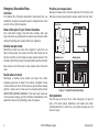
Silencing an Alarm
When the alarm bell or siren is sounding, enter your user code or present your
card to a keypad or reader during the Status List display.
All/Perimeter or Home/Sleep/Away System
IS THIS A FALSE ALARM? or CANCEL VERIFY displays.
• If a burglar alarm is valid, press NO or VERIFY to send a verification
message to the Central Station.
• If a valid alarm has not occurred, press YES or CANCEL to cancel the
alarm and send an Abort or Cancel message to the Central Station.
The keypad displays ALARM CANCELLED and the security system will
be disarmed.
What to do when a trouble tone is sounding
You can silence the trouble tone by pressing any key. This only silences the
keypad and does not correct the condition that originally caused the problem.
© 2013 Digital Monitoring Products, Inc.
Information furnished by DMP is believed to be accurate and reliable.
This information is subject to change without notice.
XT Series™ User Guide
for XT30/XT50 Series Panels
Table of Contents
SectionPage
Introduction...............................................................1
About Your Security System.............................................. 1
Emergency Evacuation Plans............................................. 2
Keypads.......................................................................... 3
Common Keys on All Keypads........................................... 6
Keypad User Options........................................................ 6
Special Keypad Tones....................................................... 7
1100 Series Wireless........................................................ 8
Special Wireless Displays.................................................. 8
Special Keypad Displays.................................................... 9
Email/Cell Phone Messages............................................. 10
MyAccess™ Text Messaging Commands........................... 10
Understanding Security System Terms............................. 10
Arming and Disarming..............................................12
How Your System Operates............................................. 12
Arming Functions........................................................... 12
Key Fob Arming.............................................................. 13
Key Fob Disarming......................................................... 13
Area System Arming....................................................... 13
Area System Disarming................................................... 14
All/Perimeter System Arming........................................... 15
All/Perimeter System Disarming....................................... 16
Home/Away System Arming............................................ 17
Home/Away System Disarming........................................ 18
SectionPage
Keypad Shortcut Keys..................................................... 19
User Menu................................................................22
Accessing the User Menu................................................ 22
User Menu Options......................................................... 22
User Check-in................................................................. 23
Zone Activity Check........................................................ 23
Sensor Reset.................................................................. 24
Outputs On/Off.............................................................. 24
Favorite......................................................................... 25
Z-Wave Setup................................................................ 25
Bypass Zones................................................................. 31
Zone Monitor................................................................. 31
Using the Zone Monitor Function..................................... 32
System Test................................................................... 32
User Codes.................................................................... 33
Schedules...................................................................... 36
Permanent Schedules..................................................... 36
Extending Schedules...................................................... 37
Output Schedules........................................................... 37
Favorite Schedules......................................................... 38
Date and Time............................................................... 38
Display Events............................................................... 39
Request Service?............................................................ 39
XT30/XT50 User Guide
i
System Setup...........................................................40
System Setup Record..................................................... 40
Protection Areas............................................................. 40
Output Record............................................................... 40
Z-Wave Device Name...................................................... 41
Favorite List................................................................... 42
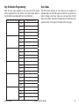
Key Fob Button Programming.......................................... 43
User Codes.................................................................... 43
Appendix D...............................................................52
Email/Cell Phone Message User’s Guide........................... 52
MyAccess™ Text Messaging Commands........................... 53
PhoneAccess™ User’s Guide............................................ 56
Common Keypad Displays............................................... 57
Quick Reference Wallet Cards..................................61
Appendix A...............................................................45
About the Display Events Section.................................... 45
Zone Activity Check Event Display................................... 45
Zone Bypass Event Displays............................................ 45
Zone Event Displays....................................................... 46
Arming and Disarming Event Displays.............................. 46
User Check-in Event Displays.......................................... 46
User Code Change Event Displays................................... 46
Supervisory Event Displays............................................. 47
System Monitor Event Displays........................................ 47
Wireless Jamming Event Displays.................................... 47
Wireless Trouble Event Displays....................................... 47
Appendix B...............................................................48
1100 Series Wireless Description .................................... 48
Appendix C...............................................................49
User’s Guide.................................................................. 49
Entering User Names ..................................................... 51
ii
XT30/XT50 User Guide
Introduction
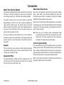
About Your Security System
A Note About False Alarms
Your system is designed with your safety and comfort in mind. It uses
the latest in computer technology to create the most advanced,
user friendly, security, fire, and access control system available.
The system combines ease of use with a simple to understand
keypad display to offer the full range of features requested by
today’s security system owners. Your security system can protect
both the interior and perimeter of your home or business while you
are away or just the perimeter when you are inside, giving you a
wall of security and peace of mind.
You can turn portions of your protection on or off at any time by
pressing a few keys. You can add, delete, and change personal user
codes at any time or check the status of all protection devices in
the system.
Keypads
This is the device we have placed at certain locations throughout
the premises that allows you to turn the system protection on and
off using your personal user code.
Keypad User Menu
The keypad provides a simple User Menu containing all of the
functions you need to fully operate your system such as changing
the time of day or a personal user code.
Introduction
One of the most important concerns facing the security industry
today is false alarms. The accidental dispatching of police and
fire agencies places others in jeopardy by limiting the response
capability of those emergency service units.
As part of our commitment to reducing false alarms, we would like
to encourage you to read this guide thoroughly. All the information
contained here can help you quickly, and comfortably, learn the XT
Series™ system operation.
Note: There may be a 30-second alarm communication delay
pre‑programmed at installation to allow disarming if a false
alarm occurs. This delay is optional and can be removed or
increased to 45 seconds by your alarm dealer.
Test Your System Weekly
It is recommended that you test the burglary portion of your system
at least once each week. Testing should involve an active test of all
doors, windows, and motion detectors connected to your system. If
your system also has fire protection, call the service department to
find out how this portion of your system should be tested.
Refer to the System Test section of this guide for instructions on
testing the burglary portion of your system.
XT30/XT50 User Guide
1
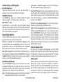
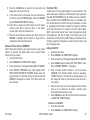
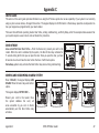
Emergency Evacuation Plans
Practice your escape plans
Overview
The National Fire Protection Association recommends that you
establish an emergency evacuation plan to safeguard lives in the
event of a fire or other emergency.
Devising an escape plan is only the beginning. For the plan to be
effective everyone should practice escape routes from each room.
First Floor
Second Floor
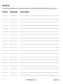
Draw a floor plan of your home or business
On a clean sheet of paper, draw the walls, windows, doors, and
stairs. Also draw any obstacles that a person may encounter while
exiting the building such as large furniture or appliances.
Fire Escape
Develop escape routes
Window Ladder
Determine at least two routes the occupants in each room can
take to safely escape. One route can be the most obvious such as
the door. Another can be through an easily opened window. If the
window is high off the ground, an escape ladder should be provided.
Building Front
Building Back
Draw arrows on the floor plan to show escape routes from each
room.
Decide where to meet
Prearrange a meeting place outside and away from where
emergency personnel are likely to be working. A neighbor’s house
or across the street in front of the house are good locations. Always
perform a head count to make sure all occupants safely exited.
NEVER ENTER A BURNING BUILDING. If the head count shows one
or more persons missing, give this information immediately to the
authorities. Never enter a building to look for someone.
2
Figure 1: Sample Escape Route Map
Early detection
The best way to survive a fire or other emergency is to get out
early. A fire alarm system installation, with smoke and carbon
monoxide detectors in each room, can greatly decrease your risk
of loss or injury.
XT30/XT50 User Guide
Introduction
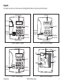
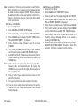
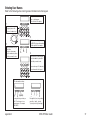
Keypads
Your system may have one or more easy to use LCD keypads that allow you to properly operate the system.
32-Character Display
Power LED
Icon Display
ABC PRINTING
F R I 2 : 51 AM
Armed LED
Backlit Logo
and Proximity
Antenna
Select Keys
1
2
3
4
5
6
7
8
9
0
CMD
COMMAND Key
Select Keys
Backlit Logo
and Proximity
Antenna
COMMAND Key
Back Arrow Key
Back Arrow Key
Data Entry Digit keys
Shortcut and Digit keys
Thinline™/Aqualite™ Keypad
Thinline™ Series Icon Keypad
32-Character Display
Interactive Shield
Proximity Card
Reader
Dealer
Logo
SMITH RESIDENCE
FRI
12:51 PM
MON 5:35 AM
Panic
Select Keys
CURRENT
Chime
HI LO
Check-In
82
TODAY
Local Weather
Conditions
98 77
HI
80
DISARMED
Reset
Micro SD
Card Slot
Carousel
Menu
LO
WEDNESDAY 74
Backlit Logo
and Proximity
Antenna
COMMAND Key
Back Arrow Key
Data Entry Digit keys
Thinline™ Wireless Keypad
Introduction
Graphic Touchscreen Keypad
XT30/XT50 User Guide
3
The Select keys
Power/Armed LED
Thinline™, Aqualite™, Icon and Wireless Keypads:
There are four keys under the display called the Select keys. These
keys are one of the features that make your system so easy to
operate. They allow you to make selections by pressing the Select
key under a choice shown in the display.
Thinline™, and Aqualite™ Keypads:
The Power LED indicates the panel Power status. It is recommended
you contact the service department when the Power LED is off or
blinks.
Note: F
or the purposes of this guide, when instructed to press the
first Select key, press the far left Select key; the second
Select key is the second from the left; third Select key is
second from the right; and the fourth Select key is the far
right key.
Clear Touch™ and Graphic Touchscreen Keypads:
There are four Select Areas in the display. These Select Areas are
one of the features that make your system so easy to operate.
They allow you to make selections by touching the area to choose
the item in the display.
Select Area 2
Select Area 1
Select Area 3
Select Area 4
LED Operation
AC
Battery
ON (Steady)
OK
OK
OFF
Trouble
N/A
BLINKS
OK
Trouble
The Armed LED is ON steady anytime any burglary protection area
is armed and is OFF when ALL areas are disarmed.
Clear Touch™ and Graphic Touchsreen Keypads:
The LED indicates the Power and Armed status of the panel.
Depending on the operation, the LED displays in Red or Blue as
listed in the table.
Color and Activity
Blue Steady
Blue Blinking
No Light
Red Steady
Red/Blue Alternate
Red Blinking
32-Character Display
Touch Select Areas
LED Operation
Panel Disarmed, AC Power OK, Battery OK
Panel Disarmed, AC Power OK, Battery Fault
Panel Disarmed, AC Power Fault, Battery OK
Panel Armed, AC Power OK, Battery OK
Panel Armed, AC Power OK, Battery Fault
Panel Armed, AC Power Fault, Battery OK
Note: For the purposes of this guide when using Clear Touch™ or
Graphic Touchscreen Keypads, when instructed to press the first
Select key, touch Select Area 1; the second Select key touch Select
Area 2; third Select key touch Select Area 3; and the fourth Select
key touch Select Area 4.
4
XT30/XT50 User Guide
Introduction
Power/Armed Logo
Thinline™ Wireless Keypads:
The backlit logo on the keypad indicates the keypad Power status
and Armed status of the panel. Depending on the operation, the
logo displays Red or Green as listed in the table.
Color and Activity
Green Steady
Green Blinking
No Light
Red Steady
Red/Green Alternate
Red Blinking
Armed Status
Panel Disarmed
Panel Disarmed
Panel Disarmed
Panel Armed
Panel Armed
Panel Armed
Keypad Power Status
AC Power OK, Battery OK
AC Power OK, Battery Fault
AC Power Fault, Battery OK
AC Power OK, Battery OK
AC Power OK, Battery Fault
AC Power Fault, Battery OK
Panic Functions
Your keypad may be set up to send a Panic, Emergency, or Fire
report to the central station. This function is optional. If this option
is programmed for your keypad, icons display below the top row
Select keys/areas.
Thinline™, Aqualite™, Icon and Wireless Keypads:
Press and hold the two Select keys adjacent to the desired icon for
2 seconds, until a beep from the keypad is heard.
Clear Touch™ and Graphic Touchscreen Keypads:
Touch the icon for 2 seconds until a beep is heard.
PRESS AND HOLD BUTTON TO SEND
PANIC OPTIONS
Touch Select Areas
POLICE
Police
Emergency
EMERGENCY
FIRE
Fire
Clear Touch™ Keypad Panic Icons Graphic Touchscreen Panic Icons
7/0 Panic Function
Thinline™, and Aqualite™ Keypads:
Security Command™, Thinline™, and Aqualite™ Keypads may also be
programmed at installation to allow the user to initiate an optional
Panic alarm by simultaneously pressing and holding the 7 and 0
(zero) keys. When the 7 and 0 keys are pressed for a short time, the
keypad sends a Panic alarm report to the central station.
Note: N
ote: The 7/0 Panic Function is not available on Clear
Touch™, Thinline™ Icon, Wireless, or Graphic Touchscreen
keypads.
Top Row Select Keys
Police
Emergency
Fire
Thinline™/Aqualite™/Thinline™ Icon Keypad Panic Keys
With Shaded Buttons To Indicate Police Panic Keys
Introduction
XT30/XT50 User Guide
5
Common Keys on All Keypads
Data Entry Digit keys
These keys allow you to enter your user code when arming or
disarming or enter other information into the system.
COMMAND (CMD) key
The COMMAND key allows you to advance through the keypad
displays, User Menu, or complete a data entry function.
Back Arrow (<—) key
The Back Arrow (<—) key is used to go back through the keypad
displays while operating your system. You can press the Back Arrow
key to back up through the list of functions in the User Menu or to
erase the last character you entered.
Keypad User Options
The User Options menu allows you to make adjustments to your
keypad to best fit your environment and needs.
Thinline™, Aqualite™, Icon and Wireless Keypads: Press
and hold the Back Arrow and COMMAND keys for two seconds. The
keypad display changes to SET BRIGHTNESS. Press the COMMAND
key to display the next option or the Back Arrow key to exit.
Clear Touch™ Keypads: Touch and hold the center of the logo icon
for two seconds. The display changes to SET BRIGHTNESS. Touch the
COMMAND (CMD) key to display the next option or touch the Back
Arrow (<—) to exit the User Options function.
Backlighting Brightness
At the SET BRIGHTNESS display, use the left Select key to lower
the keypad brightness. Use the right Select key to increase the
brightness. On Thinline™ Icon Series keypads, enter the desired
brightness from the range of off (0) to maximum (8).
Note: If the brightness level is lowered, it temporarily reverts back
to maximum intensity whenever a key is pressed.
6
XT30/XT50
On Thinline™, or Aqualite™ Keypads: This sets the LCD display, AC
LED, and keyboard backlighting brightness level.
Clear Touch™ Keypads: The user selected brightness may be set to
off which allows the backlighting to turn off (clear glass). Simply
touch the glass anywhere and the backlight illuminates for data
entry. When the speaker is sounding, the backlight illuminates at
one-half (1/2) brightness.
Thinline™ Icon and Wireless Keypads: This sets the LCD display,
keyboard, and logo backlighting brightness level.
Graphic Touchscreen Keypads: Set the backlight illumination and
AC Power/Armed LED brightness level. In the touchscreen display
below SET BRIGHTNESS, press the left < to lower and the right > to
raise the backlight brightness. If the brightness level is lowered,
it reverts to maximum intensity whenever the screen is pressed
during normal operation. If the screen is not pressed, and the
speaker has not sounded for 30 seconds, the user-selected standby
brightness level restores.
Internal Speaker Tone
Set the tone of the keypad internal speaker. At the SET TONE
display, use the top left Select key to make the tone lower. Use the
right Select key to make the tone higher. On Thinline™ Icon Series
keypads, enter the desired speaker tone from the range of 1-8.
Volume level
Set the volume level of the keypad internal speaker for key presses.
During alarm, trouble, and prewarn conditions, the volume is
always at maximum level. At SET VOLUME LEVEL, use the left Select
key to lower the keypad volume. Use the right Select key to raise
the volume. On Thinline™ Icon Series keypads, enter the desired
speaker volume level from the range of off (0) to maximum (8).
User Guide
Introduction
Model Number
Serial Number
open an entry delay door on a system that is armed (turned on)
reminding you to disarm the burglary protection.
Your system will silence the tone as soon as the first user code
digit key is pressed. If a valid user code is not entered within 5
seconds or an invalid user code is entered, the prewarn tone begins
sounding again.
Thinline™ Wireless Keypads:
The serial number assigned to the keypad displays. Press the Back
Arrow key to exit the User Options function.
Keypad Address
Exit tone: When fully arming your system to leave, a continuous
pulsing tone sounds during the exit countdown just after arming to
remind you to exit the premise. At ten seconds prior to the end of
the countdown, the rate of pulsing increases.
The current address assigned to the keypad displays, but cannot
be changed. Press the Back Arrow key to exit the User Options
function.
Monitor tone: A pulsed tone that sounds one time for one second
each time a door or window is opened while you are using the zone
monitor function from the User Menu. See Zone Monitor.
Thinline™, Aqualite™, Wireless, Clear Touch, and Graphic
Touchscreen Keypads:
The keypad model number, firmware version, and date display, but
cannot be changed.
Special Keypad Tones
Your keypad also contains a small speaker that alerts you about
events as they occur on your system. For burglary alarms, the tone
will silence as soon as the first user code digit key is pressed. If a
valid user code is not entered within 5 seconds or an invalid user
code is entered, the tone begins sounding again.
Below are brief descriptions of the different tones you hear from
the keypad.
Trouble tone: A steady tone indicating a trouble condition on your
system. Press any key to silence the trouble tone.
What to do when the trouble tone sounds
You can silence the trouble tone by pressing any key.
This only silences the keypad and does not correct the
condition that originally caused the trouble.
Fire alert: An intermittent sweeping siren from LCD keypads only
that continuously repeats until the fire alarm is silenced. This is in
addition to the bell output from the alarm panel.
Burglary alert: A siren tone from LCD keypads only that continues
until the alarm is silenced. This is in addition to the bell output
from the alarm panel.
Key press tone: A short beep as you press a key on the keypad.
Prewarn tone: A continuous pulsed tone that sounds when you
Introduction
XT30/XT50 User Guide
7
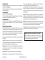
Special Wireless Displays
1100 Series Wireless
Your system may include wireless devices such as key fob(s). There
are three types of wireless key fobs available:
4-Button Model 1145-4 Key Fob
2-Button Model 1145-2 Key Fob
4-Button Layout
LED
1-Button Model 1145-1 Key Fob
The drawing shows the button
layout for all three models for your
reference. Each button on the key
TOP
fob is programmed to perform a
specific action. The button names
LFT
RGT
are listed for your reference.
TOP = the Key Fob Top button
BTM
BTM = the Key Fob Bottom button
LFT = the Key Fob Left button
RGT = the Key Fob Right button
The button programming list for the
key fob(s) connected to your system
is located in the System Setup section
of this guide. Refer to Appendix B for
LED Status operation information.
Specific function labels can be added
to each button to indicate button
operation.
For best operation, allow the LED
to turn on and then turn off before
pressing another button. The key
fob may not complete sending the
signal for the button press if another
button is pressed too soon.
8
Connect Keyring or Lanyard Here
2-Button Layout
Your system may use wireless transmitters to send alarm and
trouble information from the protection devices to the panel.
Wireless systems have a few unique keypad displays.
BACK DOOR -LOBAT - (Low Battery) The battery in a wireless
transmitter is low. (BACK DOOR is used as an example only.)
BACK DOOR -MISNG - (Missing) The panel is not receiving the
wireless transmitter periodic test report.
WIRELESS -TRBL - (Trouble) Some part of your wireless system is
operating improperly. Call the service department for assistance.
WIRELESS RECEIVER JAMMED -ALARM - Your system may be
programmed for wireless interference detection and, if displayed,
your wireless receiver has detected an interfering signal while the
system is armed.
WIRELESS RECEIVER JAMMED -TRBL - (Trouble) Your system may be
programmed for wireless interference detection and, if displayed,
your wireless receiver has detected an interfering signal while the
system is disarmed.
1-Button Layout
TOP
TOP
BTM
Key Fob Examples and
Button Names
XT30/XT50 User Guide
Introduction
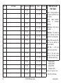
Special Keypad Displays
TRY AGAIN or INVALID CODE
As you use your system, you may occasionally see a keypad display
that asks you to enter a user code or describes a condition on the
system. Below are some examples of the displays you may see.
TRBL (TROUBLE)
ALARM
A 24-hour zone, such as a fire or panic zone, or an armed burglary
zone is faulted. Your system may sound bells or sirens.
The code entered is not recognized by the system. Check the user
code and try again.
There is a problem with a protection device or system component.
This display is accompanied by a description of the problem.
ALARM NOT SENT
SYSTEM TROUBLE or SERVICE REQUIRED
The alarm signal was aborted and was not sent to the central station
because a user code was entered to disarm the system before the
alarm signal was sent to the central station. Also, your system may
be pre-programmed at installation to send an Abort signal to the
Central Station. Refer to the Introduction section.
TEST IN PROGRESS
There is an electronic failure in your system. Contact the service
department as soon as possible.
The system is currently being tested by an installation or service
technician.
ALARM CANCELLED
An Alarm signal just sent to the central station was cancelled
because a user code was entered after the alarm was sent. Also, an
Alarm Cancel signal is sent to the Central Station.
ALARM VERIFIED
A valid burglar alarm has occurred and has been manually verified
by the user. The alarm system also transmits a VERIFY message to
the Central Station.
ENTER CODE
The system requires you to enter a personal user code. User codes
can be used for turning your system on (arming), turning your
system off (disarming), and other system options.
As you enter your user code, the keypad display shows an asterisk
(*) in place of each digit pressed. This prevents others from seeing
your user code on the display as you enter it.
Introduction
XT30/XT50 User Guide
9
Email/Cell Phone Messages
Disarming
Your system may be programmed at installation to send a variety of
messages to your personal email, and cell phone.
The message option uses your security system’s reporting capability
to send reports using an email address or cell phone number in
much the same way as someone sending an email would do. You
can receive reports of alarms, troubles, or system armings and
disarmings and know at a glance your system status. See Appendix
D for more information.
MyAccess™ Text Messaging Commands
Your system may be programmed to allow simple text messages to
be sent to the security system and perform basic user operations.
By texting a message from your cell phone or PDA, the following
actions can be performed: Arm/Disarm, check Armed Status, Cancel
Alarm, and turn Outputs On/Off. Other operations that may be
programmed from your cell phone or PDA include: Turning on and
off lights, Locking and unlocking doors, and Setting the thermostat.
See Appendix D for more information.
This means turning off one or more areas of the system. When
disarmed, the system does NOT sound alarms or send alarm reports
to a central station when a burglary zone faults.
Zone
A zone refers to one or more protected openings or protection
devices assigned the same zone number. Each door or window,
motion detector, smoke detector, or other device has a zone
number and a name.
Often, similar devices in the same general area share the same
zone. For example, the windows on the east side of the premises
can all be grouped together in a zone named E. WINDOWS.
Entry or Exit Zone
Throughout this guide, and in some displays on your keypad, you
may see certain words or phrases that might be unfamiliar.
Below are some terms you will see here and on the keypad display.
Almost all systems have one or more doors through which you can
enter or exit the premises. These doors are programmed with a
delay time to allow you to enter or exit while the system is armed
without setting off the alarm.
When you arm the system, activity on all burglary zones is ignored
until the programmed exit delay time expires. Once that time has
expired and the system is fully armed, opening the door causes the
panel to start the entry delay time. During the entry delay time,
enter a valid user code to disarm the system or an alarm occurs.
Arming
Instant Zone
This is the term used for turning on the burglary protection in one
or more areas of the system. Your system may require you to enter
a user code. When armed, the system can sound alarm bells or
sirens and, if monitored, send alarm reports to a central station
when a burglary zone is faulted.
Fire, panic, and other 24-hour devices are always turned on and do
not need to be armed.
Exterior windows and non-entry doors, or interior protection
devices, are typically not programmed with delay times. If these
zones fault while the system is armed, an alarm occurs instantly.
Understanding Security System Terms
10
24-Hour Zone
A 24-hour zone is not turned on or off by arming or disarming your
system. Some examples of 24-hour zones are fire zones, panic
zones, and temperature control zones.
XT30/XT50 User Guide
Introduction
Areas
An area is made up of burglary zones that can be armed or disarmed
together. The Perimeter area, for example, consists of all the doors
and windows on the outside of the building. When you arm the
Perimeter, these zones sound an alarm if tripped.
Central Station Monitoring
Your system can also be programmed to automatically send alarm,
trouble, and arming and disarming reports to a central station.
Operators at the central station can then dispatch the appropriate
authorities or contact you with the specific event information.
Status
Status is a feature that automatically displays the system armed
or disarmed status on the keypads. Alarm or trouble conditions on
a zone or a system monitor such as AC or battery trouble can also
display. There are two types of status information available: Status
List and Armed Status.
Status List
The keypad Status List displays any alarm or trouble condition on
a zone and any trouble condition that occurs with the AC power or
battery power. If your system contains any Panic zones, these do
not display on the keypad for security reasons.
If an alarm occurs on a non-fire, 24-hour zone or a system monitor,
it remains in the Status List until it restores. If one or more armed
burglary zones trips, the last one to trip remains in the Status List.
The burglary zone alarm remains in the Status List until it is cleared
by disarming the system.
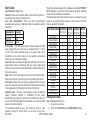
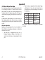
Armed Status
With Armed Status, the keypad displays the current armed condition
of areas within your security system.
The keypad displays
HOME SYSTEM ON
When
The perimeter areas is armed in a
Home/Away system.
PERIMETER ON
The perimeter is armed in an All/
Perimeter system.
ALL SYSTEM ON
All areas are on.
SLEEP SYSTEM ON
The perimeter and interior areas are on
but the bedroom area is off.
Also, for keypads that include an Armed LED, the Armed LED is ON
steady anytime a burglary protection area is armed and OFF when
ALL areas are disarmed.
Exit Error
This is an automatic panel function that occurs if an exit door does
not close all the way after the system is armed.
For example, if the front door is left ajar upon exit and the exit delay
time expires, the system attempts to arm the front door zone but
recognizes the open condition. The system sounds the alarm sirens
and starts the entry delay. If the open condition is not corrected, an
alarm and exit error is reported to the central station.
The Exit Error feature allows the central station to acknowledge
the arming error without dispatching the police on a false alarm.
Zone Status
To display the status of a particular zone, enter the zone number
followed by the COMMAND key when the keypad displays the Status
List.
Introduction
XT30/XT50 User Guide
11
Arming and Disarming
How Your System Operates
Your system has been programmed to operate in one of three
modes: Area, All/Perimeter or Home/Sleep/Away.
• Area — Your burglary protection is divided into up to six
areas. Each area can have a custom name, be turned on or off
independently of other areas, and limit access to only those
users with proper authority.
• All/Perimeter — Your burglary protection is divided into two
areas: Interior and Perimeter.
Perimeter arming is for when you are staying inside but want
the comfort of knowing the exterior doors and windows are
armed. Perimeter arming allows you to move freely about inside
without setting off any interior alarms.
All arms both the Perimeter and the Interior of the system. You
want to arm both of these areas when leaving the building and
no one is left inside.
• Home/Sleep/Away — Your burglary protection is divided into
two or three areas: Perimeter, Interior, and Bedrooms.
Home (Perimeter) arming is for when you are staying inside but
want the comfort of knowing the exterior doors and windows are
armed.
Sleep (Perimeter and Interior) arms all areas except those near
bedrooms and nighttime areas.
Away (Perimeter, Interior, and Bedrooms) arms all three areas
for when you leave the building and no one is left inside.
Arming Functions
Arming: During arming, the system verifies that all doors, windows,
and other protection devices to be armed are in normal condition.
If everything is normal, the system arms. If there is a problem on
one or more burglary zones, the keypad displays the problem and
allows you to correct the problem or bypass those zones.
If the problem can be corrected by closing a door or window, do
not bypass the zone. Instead, correct the problem and try arming
again. If the problem cannot be corrected, you can bypass the zone
or wait until the zone can be repaired by a service technician. A
bypassed zone is ignored by the system during the armed period.
In some cases the keypad might display FRONT DOOR - FAULT.
The keypad may then display PRIORITY ZONE, which is a zone that
cannot be bypassed. The problem on the zone must be corrected
before the system can be armed.
After making your arming selection, the keypad displays any zones
that are currently bypassed. These zones remain bypassed until the
system is armed and then disarmed. Any 24-hour zones in a faulted
condition also display.
Armed Message: After completing all bypasses or correcting zone
faults, the areas selected are armed.
For All/Perimeter systems the keypad briefly displays ALL SYSTEM
ON if all areas in the system are arming or PERIMETER ON if only
selected areas are arming.
For Home/Away or Home/Sleep/Away systems the keypad displays
ALL SYSTEM ON if all areas in the system are arming, HOME SYSTEM
ON or SLEEP SYSTEM ON if only selected areas are arming.
Regardless of which mode is programmed, much of the operation
is similar. Throughout this guide, any differences between the
systems are noted for your convenience.
12
XT30/XT50 User Guide
Arming and Disarming
Exit Delay: The keypad then displays the exit delay time as it counts
down. If the entire system has been armed, your system beeps the
exit delay tone at eight-second intervals until the last 10 seconds
when the keypad beeps at three‑second intervals. After exiting the
building, if you re-enter during the countdown the exit countdown
restarts, allowing additional time to then disarm or again exit the
building during the countdown. This restart can occur only one
time. When the exit delay time expires, all disarmed zones are
armed. If your system uses a keyswitch to arm an area, the exit
delay time does NOT count down on the keypad display.
Key Fob Arming
When you arm both the Perimeter and Interior to leave the building
but then you do not exit by the time the exit delay ends, the system
automatically arms but the interior area(s) will remain disarmed
because you have not exited.
Area System Arming
Should you exit the building and the door does not close properly,
your system may be programmed so that when the exit delay
countdown ends, then the entry delay starts and the bell will sound
to alert you to the situation. Enter your user code to stop the bell
and disarm the system. Rearm the system, exit the building, and
make sure the door is securely closed.
Arming or Disarming: You can arm and disarm all areas at one time
or each area individually. You can only arm or disarm areas authorized
for your user code.
ONE MOMENT . . . Message: If your system is monitored, it
may be programmed to wait for the arming report to be sent to
the monitoring station before displaying the armed message. (See
Arming Report below.) This verifies that the arming message was
received by your monitoring station. While the system waits, the
display reads ONE MOMENT.... If the report is received, the keypad
buzzes for one second and displays the armed message. If the
report is not received, the keypad displays LOCAL ALARM ONLY
before displaying the armed message.
Arming Report: Your system may be pre-programmed at installation
to send arming or zone bypass reports to a central station.
Arming and Disarming
Press the key fob button programmed for Arming or Toggle (Arm/
Disarm) button. A Red LED two-second acknowledgement indicates
All System On. A Green/Red two‑second acknowledgement indicates
System On with some areas armed.
Key Fob Disarming
Press the key fob button programmed for Disarming or Toggle
(Arm/Disarm) button. A Green LED two-second acknowledgement
indicates All System Off.
Area Assignment: Your security system is programmed into separate
areas. The number of areas and their names are listed in the back
of this guide.
All or Selective Arming: After entering your user code, the system
allows you to arm either all of the areas to which you have access
or one or more selected areas. If you choose to arm all areas, the
system begins verifying that all zones in those areas are in a good
condition. If you choose to arm selected areas, the system prompts
you to choose the areas you want to arm.
Arming the System
1. Press the COMMAND key until ARM DISARM displays.
2.Select ARM to turn on all protection.
3. Enter your user code if required. The display reads
ALL? NO YES.
4.Select NO to arm only selected areas. Go to step 5. Select
YES to arm all areas authorized for your user code.
XT30/XT50 User Guide
13
5.If NO is selected in step 4, the display begins to list each
area to which you have access followed by NO YES.
Example: OFFICE NO YES.
5a.Select YES for each area you want to arm.
5b.Select NO for each area you do NOT want to arm.
Note: You can also simply press the area numbers you want
to arm while ALL? NO YES displays. This changes the
display to AREAS:. The numbers you select appear
in the display. For example: AREAS: 2
4. Press
COMMAND when done.
6. The system displays any faulted and bypassed zones in the
following order: faulted burglary zones, bypassed burglary
zones, faulted 24-hour zones, and bypassed 24-hour zones.
7. At this point you can force arm or bypass any faulted
burglary zones. A zone that is force armed is restored into the
system if it later returns to normal. A zone that is bypassed
remains bypassed until the system is disarmed. See steps 7a
through 7d.
7a. If a problem exists on any zones, the zone name and
problem are shown followed by: OKAY BYPASS STOP.
7b.Select OKAY to force arm the zone(s) before arming.
7c.Select BYPASS to bypass the zone(s) before arming.
Note: 24-hour zones cannot be bypassed.
7d.Select STOP to stop the system from arming. Correct
the zone problem(s) and return to step 1.
8. The display reads SYSTEM ON if at least one area in the
system is armed, and ALL SYSTEM ON if all areas in the
system are armed.
9. The keypad then displays the exit time in seconds and
counts down the remaining time: EXIT: # # (# # = seconds
remaining). When the entire system is armed, the keypad
sounds the exit delay alert and when the delay expires, all
zones are armed.
14
Area System Disarming
Disarming: While the system is armed, you can only enter the premises
through an exit/entry delay door without causing an alarm. After
opening the door, the keypad sounds a prewarn tone to remind you
to disarm the system. You must disarm the system before the delay
time expires or an alarm on the door zone occurs.
During the prewarn tone, the keypad displays ENTER CODE: Enter
your user code to disarm the system. Only those areas authorized
for your user code disarm.
Note: Your system will silence the tone as soon as the first user code
digit key is pressed. If a valid user code is not entered within
5 seconds or an invalid user code is entered, the prewarn tone
begins sounding again.
All or Selective Disarming: After entering your user code, the system
allows you to disarm either all of the areas to which you have access
or just selected areas. If you choose to disarm all areas, the system
automatically disarms them. If you choose to disarm selected areas,
the names of those areas display on the keypad.
Z-Wave Lock Disarming: If your system is installed with a Z-Wave
compatible lock, a valid user code entered at the lock will unlock
the door and disarm the areas to which you have access.
Alarm Display: After disarming, the keypad displays any zones that
went into alarm or any communication problems that occurred
during the armed period. All burglary zones are then disarmed and
any bypassed zones are automatically reset.
Disarmed Message: The keypad displays ALL SYSTEM OFF after the
system disarms.
Central Station Report: Your system may be pre-programmed at
installation to send a report of the disarming to the central station.
XT30/XT50 User Guide
Arming and Disarming
Disarming an Area System
1. Press the COMMAND key until ARM DISARM displays. During
entry delay this process starts at step 3 below.
2.Select DISARM to disarm areas.
3. The keypad displays ENTER CODE: . Enter your user code
and press COMMAND. The keypad displays ALL? NO YES.
4.Select YES to disarm all areas authorized for your user
code.
4a.Select NO to disarm only certain areas individually. The
keypad then displays the name of each area authorized for
your code followed by the NO YES display.
4b.Select YES to disarm the area displayed.
4c.Select NO to not disarm and to display the next area.
Note: You can also just press the area numbers you want to
disarm while at the ALL? NO YES display. This changes the
display to AREAS: . The area numbers you select appear in
the display. For example: AREAS: 2 4.
To remove an area number from the display, press its
corresponding number on the keypad. Press COMMAND
when done.
5. After all areas have displayed, any alarms or communication
problems that occurred during the armed period are shown.
6.If all areas are
ALL SYSTEM OFF.
disarmed,
the
keypad
displays
All/Perimeter System Arming
Area Assignment: Your security system is divided into two separate
areas. Motion detectors, inside doors, and other interior protection
devices are assigned to the Interior area while windows and exterior
doors are assigned to the Perimeter area.
Perimeter or All: When arming an All/Perimeter system, the keypad
displays PERIM ALL. If you select ALL, you arm both the Perimeter
and the Interior of the system. You want to arm both of these areas
when leaving with nobody left inside. Selecting PERIM arms only
the Perimeter of the system. Perimeter arming is for when you are
staying inside but want the comfort of knowing the exterior doors
and windows are armed. Perimeter arming allows you to move freely
about inside without setting off any interior alarms.
System Ready/System Not Ready Keypad Displays
When all zones in the system are in a normal condition, the keypad
displays SYSTEM READY. If there are one or more zones that are
not in a normal condition, the keypad displays SYSTEM NOT READY.
Pressing any Select key during this display shows the zone name
allowing you to investigate the problem.
Instant Arming
Instant: During the exit delay time, you can cancel the exit and
entry delays and cause all zones to be instant zones. Select INSTNT
while the exit delay displays. This immediately arms the exit zones.
However, no entry delay is provided and an alarm immediately
occurs should an entry door be opened.
All/Perimeter Shortcut Key Arming
Arm Perimeter — Press 6 for 2 seconds.
Arm All— Press 1 for 2 seconds.
Arming and Disarming
XT30/XT50 User Guide
15
Arming an All/Perimeter System
1. Enter your code. The keypad displays PERIM ALL.
2.Select PERIM to arm the Perimeter area only.
3.Select ALL to arm both the Perimeter and Interior areas.
4. The system displays any faulted and bypassed zones in the
following order: faulted burglary zones, bypassed burglary
zones, faulted 24-hour zones, and bypassed 24-hour zones.
5. At this point you can force arm or bypass any faulted
burglary zones. A zone that is force armed is restored into
the system if it later returns to normal. A bypassed zone
remains bypassed until the system is disarmed. See steps 5a
through 5d.
5a. If a problem exists on any zones, the zone name and problem
display followed by: OKAY BYPASS STOP.
5b.Select OKAY to force arm the zone(s) before arming.
5c.Select BYPASS to bypass the zone(s) before arming.
5d.Select STOP to stop the system from arming. Correct the
zone problem(s) and return to step 1.
6. The keypad displays PERIMETER ON if only the perimeter is
being armed and ALL SYSTEM ON if both the perimeter and
interior are being armed.
7. The keypad next displays EXIT: ## INSTNT and begins to
count down the number of seconds remaining for you to
exit. If the entire system is armed, the keypad sounds the
exit delay alert and when the delay expires, all zones are
armed.
8. You can select INSTNT while EXIT: ## INSTNT displays to
immediately arm all zones and make them instant. The
keypad displays INSTANT. When you select INSTANT, any
entry/exit zone that trips immediately activates an alarm
and the exit delay countdown immediately stops.
16
XT30/XT50
9. When the system is armed, the keypad displays PERIMETER
ON for perimeter arming and ALL SYSTEM ON for perimeter
and interior arming.
All/Perimeter System Disarming
Disarming: While the system is armed, you can only enter the
premises through an entry/exit delay door without causing an
alarm. After opening the door, the keypad sounds a prewarn tone
to remind you to disarm the system. You must disarm the system
before the prewarn tone expires or an alarm on the door zone
occurs.
During the prewarn tone, the keypad displays ENTER CODE:. Enter
your user code to disarm the system.
Note: Your system will silence the tone as soon as the first user
code digit key is pressed. If a valid user code is not entered within 5
seconds or an invalid user code is entered, the prewarn tone begins
sounding again.
Alarm Display: After disarming, the keypad displays any zones
that tripped or any transmission problems that occurred during the
armed period. All burglary zones are then disarmed and any by
passed zones automatically reset.
Disarmed Message: The keypad displays ALL SYSTEM OFF after the
system disarms.
Central Station Report: Your system may be pre-programmed at
installation to send a report of the system disarming to the central
station.
Z-Wave Lock Disarming: If your system is installed with a Z-Wave
compatible lock, a valid user code entered at the lock will unlock
the door and disarm the system.
User Guide
Arming and Disarming
Disarming an All/Perimeter System
1. During the entry delay time, the keypad displays ENTER
CODE:. Enter your user code.
2. The keypad displays any zones that went into alarm and any
communication problems that occurred during the armed
period.
3. The keypad next displays ALL SYSTEM OFF to confirm the
system is disarmed.
Disarming During an Alarm
1. While the alarm bell or siren sounds, you may choose to
enter your user code to silence the alarm sounder.
Home/Away System Arming
Area Assignment: Your security system is divided into two or three
separate areas. Motion detectors, inside doors, and other interior
devices are assigned to an Interior and possibly Bedroom area while
windows and exterior doors, are assigned to a Perimeter area.
Arming the system: When arming a Home/Away system, the keypad
displays HOME AWAY or HOME SLEEP AWAY. If you select AWAY,
you arm all areas of the system. You want to arm all areas when
leaving with nobody staying inside.
Selecting HOME arms only the system Perimeter. Perimeter arming
is for when you are staying inside but want the comfort of knowing
the exterior doors and windows are armed.
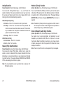
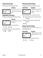
For a burglary alarm, the keypad displays
IS THIS A FALSE ALARM? or CANCEL VERIFY
and after the pre-programmed alarm communication
delay, the alarm is sent to the Central Station.
Selecting SLEEP arms the Perimeter and Interior devices but leaves
devices near bedrooms and other nighttime areas off.
This allows you to investigate the alarm prior to disarming
the system. This display remains on the keypad until a
selection is made, the Back Arrow is pressed, or the internal
system bell cutoff timer expires.
When all system zones are in a normal condition and can be armed
without bypassing, the keypad displays SYSTEM READY. If there are
one or more zones that are not in a normal condition, the keypad
displays SYSTEM NOT READY. Pressing any Select key during this
display shows the faulted zone name.
2. If a valid alarm has not occurred, Select YES or CANCEL to
disarm the system and cancel the alarm.
The keypad displays ALARM CANCELLED then ALL SYSTEM
OFF to confirm the system is disarmed.
OR
If the alarm is valid, select NO or VERIFY to send a verify
message to the Central Station.
Arming and Disarming
System Ready/System Not Ready Keypad Displays
Home/Sleep/Away Shortcut Key Arming
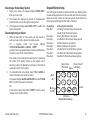
Arm Home — Press 3 for 2 seconds to arm the perimeter.
Arm Sleep — Press 7 for 2 seconds to arm the perimeter and interior
areas and leave the bedroom area off.
Arm Away — Press 1 for 2 seconds.
XT30/XT50 User Guide
17
Arming a Home/Away System
1. Enter your user code. The keypad displays HOME AWAY or
HOME SLEEP AWAY (you may have three areas).
2.Select HOME to arm the Perimeter only.
3.Select SLEEP to arm the Perimeter and Interior.
4.Select AWAY to arm the Perimeter, Interior, and Bedroom.
5. The system displays any faulted and bypassed zones in the
following order: faulted burglary zones, bypassed burglary
zones, faulted 24-hour zones, and bypassed 24-hour zones.
6. At this point you can force arm or bypass any faulted burglary
zones. A zone that is force armed is restored into the system
if it later returns to normal. A zone that is bypassed remains
bypassed until the system is disarmed. See steps 6a through
6d.
6a. If a problem exists on any zones, the zone name and problem
display followed by: OKAY BYPASS STOP.
6b.Select OKAY to force arm the zone(s) before arming.
6c.Select BYPASS to bypass the zone(s) before arming.
6d.Select STOP to stop the system from arming. Correct the
zone problem(s) and return to step 1.
7. The keypad displays HOME SYSTEM ON if you selected
HOME, or SLEEP SYSTEM ON if you selected SLEEP, or ALL
SYSTEM ON if you selected AWAY.
8. The keypad next displays EXIT: ## INSTNT and begins to
count down the number of seconds remaining for you to
exit. The keypad sounds the exit delay alert and when the
delay expires, all zones are armed.
9. You can select INSTNT while EXIT: ## INSTNT displays to
immediately arm all zones and make them instant. The
keypad displays INSTANT. When you select INSTANT, any
entry/exit zone that trips immediately activates an alarm
and the exit delay countdown immediately stops.
18
XT30/XT50
10.When the system is armed, the keypad displays HOME
SYSTEM ON for Perimeter arming, SLEEP SYSTEM ON for
Perimeter and Interior arming, and ALL SYSTEM ON for all
areas armed.
Home/Away System Disarming
Disarming: While the system is armed, you can only enter the
premises through an entry/exit delay door without causing an
alarm. After opening the door, the keypad sounds a prewarn tone
to remind you to disarm the system. You must disarm the system
before the prewarn tone expires or an alarm on the door occurs.
During the prewarn tone, the keypad displays ENTER CODE:. Enter
your code to disarm the system.
Note: Your system will silence the tone as soon as the first user
code digit key is pressed. If a valid user code is not entered within 5
seconds or an invalid user code is entered, the prewarn tone begins
sounding again.
Alarm Display: After disarming, the keypad displays any zones that
tripped or any communication problems that occurred during the
armed period. All burglary zones are then disarmed and any by
passed zones automatically reset.
Disarmed Message: The keypad displays ALL SYSTEM OFF after the
system disarms.
Central Station Report: Your system may be pre-programmed at
installation to send a report of the system disarming to the central
station and/or to your email address or cell phone.
Z-Wave Lock Disarming: If your system is installed with a Z-Wave
compatible lock, a valid user code entered at the lock will unlock
the door and disarm the system.
User Guide
Arming and Disarming
Disarming a Home/Away System
1. During entry delay, the keypad displays ENTER CODE:.
Enter your user code.
2. The keypad then displays any alarms or communication
problems that occurred during the armed period.
3. The keypad next displays ALL SYSTEM OFF to confirm the
system is disarmed.
Disarming During an Alarm
1. While the alarm bell or siren sounds, you may choose to
enter your user code to silence the alarm sounder.
For
a
burglary
alarm,
the
keypad
displays
IS THIS A FALSE ALARM? or CANCEL VERIFY
and after the pre-programmed alarm communication delay,
the alarm is sent to the Central Station.
This allows you to investigate the alarm prior to disarming
the system. This display remains on the keypad until a
selection is made, the Back Arrow is pressed, or the internal
system bell cutoff timer expires.
2. If a valid alarm has not occurred, Select YES or CANCEL to
disarm the system and cancel the alarm.
The keypad displays ALARM CANCELLED then ALL SYSTEM
OFF to confirm the system is disarmed.
OR
If the alarm is valid, select NO or VERIFY to send a verify
message to the Central Station.
Arming and Disarming
Keypad Shortcut Keys
Your LCD keypad provides one‑button shortcut keys. Holding down
the selected keypad button for two seconds until the tone re-sounds
allows you to arm, monitor, or reset your system. These options can
still be accessed through the User Menu if desired.
Keypad Key
Arming System Operation
Press Key 1
Arm Away for Home/Sleep/Away systems
Arm All for All/Perimeter systems
Press Key 2
Sensor (Fire) Reset on all systems
Press Key 3
Arm Home for Home/Sleep/Away systems
Press Key 4
Check-in Report on all systems
Press Key 5
Monitor (Chime) on all systems
Press Key 6
Arm Perimeter for All/Perimeter systems
Press Key 7
Arm Sleep for Home/Sleep/Away systems
Press Key 8
Easy Exit for Home/Sleep/Away systems
Sensor Reset
Check-in Report
(Fire Reset) Home (Latch Key)
Away
All
Monitor
(Chime)
XT30/XT50 User Guide
1
AB
5
9
C
O
MN
YZ
2
DE
F
PQ
R
6
3
GH
7
ST
I
U
0
Perimeter
Keypad Shortcut Keys
4
L
JK
8
VW
X
CMD
Easy Exit
Sleep
19
Arming Function
System Operation: Home/Sleep/Away, or All/Perimeter.
You can use the Arming shortcut keys, 1, 3, 6, and 7 when the
system is disarmed. You may be prompted to enter your user code.
If any zones are faulted, select force arm or bypass. Refer to the
Arming Section for detailed arming operation.
Home/Sleep/Away Arming
Arm Home — Press 3 for 2 seconds to arm the perimeter.
Arm Sleep — Press 7 for 2 seconds to arm the perimeter and
interior areas and leave the bedroom area off. This shortcut
key is available when the system is disarmed and when the
system is armed for Home mode.
Arm Away — Press 1 for 2 seconds.
All/Perimeter Arming
Arm Perimeter — Press 6 for 2 seconds.
Arm All— Press 1 for 2 seconds.
Sensor (Fire) Reset Function
System Operation: Area, Home/Sleep/Away, or All/Perimeter.
You can use the Sensor (Fire) Reset, shortcut key 2, when the
system is armed or disarmed. When pressed, detectors that have
latched due to an alarm condition are now restored and returned
to normal function. The keypad displays SENSORS ON and SENSORS
OFF to acknowledge the shortcut key press.
Monitor (Chime) Function
System Operation: Area, Home/Sleep/Away, or All/Perimeter.
You can use the Monitor (Chime), shortcut key 5, when the system
is disarmed. When pressed, the Zone Monitor operation is initiated.
As needed, refer to the Zone Monitor section. The keypad displays
MONITOR ON and chimes or displays MONITOR OFF and no tone is
sounded.
Note: The Monitor (Chime) shortcut key applies to all Exit zones in
an Area system and to all zones assigned to the perimeter in
a Home/Sleep/Away or All/Perimeter system.
Check-in Report (Latch Key) Function
System Operation: Area, Home/Sleep/Away, or All/Perimeter.
Your system may be pre-programmed at installation to send
messages to your personal email, PDA, or cell phone. You can use
the Check-in Report (Latch Key), shortcut key 4, to have a Checkin Report message sent. Refer to Appendix D for Email/Cell phone
message information.
Note: Check-in report function is not supported by Icon keypads.
Note: You are prompted to enter your User Code on Area or All/
Perimeter systems.
20
XT30/XT50 User Guide
Arming and Disarming
Easy Exit™ Function
System Operation: Home/Sleep/Away.
You can use the Easy Exit, shortcut key 8, when the system is
armed, to restart the exit delay allowing you to exit the premises
without disarming the system. For example, to let a pet out or
retrieve the newspaper. After the exit delay time expires, the
system automatically rearms.
You can also press the Easy Exit, shortcut key 8 again, to cancel
the exit delay countdown. For example, the telephone rings before
you retrieve the newspaper so you press shortcut key 8 to rearm
the system.
Arming and Disarming
XT30/XT50 User Guide
21
User Menu
BYPASS ZONES
Many of your system features have been put into a User Menu that
you can access from a 32-character keypad. The menu requires you
to enter your user code. Only those functions to which you have
access display.
Accessing the User Menu
1. Press the COMMAND key until MENU? NO YES displays.
2.Select YES. The keypad displays ENTER CODE: — . Enter
your user code. You can now scroll down through the list of
system features available to you.
User Menu Options
The following list shows the User Menu options in order:
Menu Option
Description
USER CHECKIN
Allows check-in with the system to
indicate arrival on premises.
Allows you to monitor a zone for nonactivity.
Resets smoke or glassbreak detectors
that have latched during an alarm
condition.
Allows you to turn on or off any of the
outputs described in the System Setup
section of this guide.
Allows you to activate any of the
Favorites described in the System Setup
section of this guide.
Allows you to Add, List, Remove,
Transfer, and Rediscover Z-Wave
devices in your system. You can create
Z-Wave Favorites, Add, Edit, and
Remove Z-Wave devices in Favorites.
ZONE ACTIVITY CHECK
SENSOR RESET
OUTPUTS ON/OFF
FAVORITES
Z-WAVE SETUP
22
Allows you to Bypass a zone or reset an
already bypassed zone.
ZONE MONITOR
Allows you to add or remove a zone from
the monitor mode.
SYSTEM TEST
Tests the system siren, communication
to the central station, and backup
battery.
USER CODES
Allows you to add, delete, or change
user codes and authority levels.
SCHEDULES
Allows you to add, remove, or change
system schedules.
DATE AND TIME
Allows you change the Day, Date, or
Time that is currently in the system.
DISPLAY EVENTS
Allows you to view the last 100 events
on the XT30 and 200 events on the XT50
that occurred on your system.
SERVICE REQUEST
Allows you to send a message to the
Central Station requesting service on
the alarm system.
The following pages detail each User Menu item and provide
instructions on when and how to use them properly.
XT30/XT50 User Guide
User Menu
User Check-in
Zone Activity Check
Function: This feature allows you to monitor the arrival of children
from school or employees to work by having a special Check-in
Report sent to your email address or cell phone if programmed.
Function: Your security system may be pre-programmed at
installation for the Zone Activity Check feature allowing you to
monitor a person for non-activity.
Note: Check-in report function does not work with Icon keypads.
Appendix D describes the Email/Cell Phone option.
When no activity is detected for the programmed time period, your
keypad sounds a steady tone for a set period of time and displays
PRESS ANY KEY. Pressing any key on the keypad, before the steady
tone stops, prevents your system from sending a “User Activity
Not Detected” report to the central station. Pressing the key also
restarts the zone activity timer.
User Code Level: Master, Standard, Limited, or Scheduled.
Sending a Check-in Report
1. After disarming the system, access the User Menu.
2. At the USER CHECKIN? display, press any Select key. The
keypad displays USER CHECKIN: 22 (22 = user number).
3. The panel sends the Check-in Report containing your
account number and user number to the email address or
cell phone number.
Check-in (Latch Key) Report Shortcut Key
All Systems (except Icon keypads) — Press 4 for 2 seconds, then
enter your user code to send a Check-in Report.
User Code Level: Master, Standard, Limited, or Scheduled.
This could be used for a person living alone to detect when they
have not moved about to trip a disarmed zone within a programmed
period of time. This feature is optional.
Note: The Zone Activity Check is disabled when a schedule is
entered to allow for sleeping hours and is automatically
enabled when an area is disarmed.
Selecting Zone Activity Check
1. At the ACTIVITY CHECK? display, press any Select key. The
keypad displays ENABLE? YES NO. The default is YES.
2.When NO is selected, the keypad displays CHECK DISABLED
for four seconds and then sends the Activity Check Disabled
message to the central station.
3.When YES is selected, the keypad displays CHECK ENABLED
for four seconds and then sends the Activity Check Enabled
message to the central station.
User Menu
XT30/XT50 User Guide
23
Sensor Reset
Outputs On/Off
Function: Resets smoke or glassbreak detectors. Also clears Fire
and Supervisory zone alarms and trouble keypad displays. Sensor
Reset also clears low battery displays if your system is using
wireless sensors.
Function: Allows you to turn the system outputs on and off.
Once smoke or glassbreak detectors trip, they must be reset before
they can detect any additional alarm conditions. When Sensor
Reset is selected, power to the detectors is temporarily removed
by the system allowing them to reset.
The system output names and numbers are located in the System
Setup section at the back of this guide.
User Code Level: Master, Standard, Limited, or Scheduled.
Make sure all smoke is cleared from around the area of the smoke
detectors before performing a Sensor Reset to prevent the alarm
from occurring again.
Resetting the Sensors
2.When SENSOR RESET? displays, press any Select key. The
keypad displays SENSORS OFF for five seconds followed by
SENSORS ON.
3. The keypad returns to the status display.
All Systems — Press 2 for 2 seconds, then enter your user code if
required, to reset the system.
24
This function is used to individually turn your system relay outputs
on and off. Your system may use these outputs to control interior and
exterior lighting, or heating, air conditioning, or other appliances.
Turning the Outputs On/Off
1. Access the User Menu.
2. Press the COMMAND key until OUTPUTS ON/OFF? displays.
3. Press any Select key.
4. The keypad displays OUTPUT: - ON OFF.
1. Access the User Menu.
Sensor (Fire) Reset Shortcut Key
User Code Level: Master, Standard, or Limited.
5. Enter the output number you want to turn on or off. The
output number appears in the display.
6. With the output number displayed, Select ON or OFF. The
output is then turned on or off, depending on your selection,
and remains in that state until you change it.
7. The system automatically removes the output number and a
new output number can be entered. Refer back to step 5.
To exit the Output menu option, press the Back Arrow key until you
return to the keypad Status List.
XT30/XT50 User Guide
User Menu
Favorite
Z-Wave Setup
User Code Level: Master, Standard, or Limited.
Allows you to activate a Z-Wave Favorite. Z-Wave devices can
be grouped together to create Favorites. Favorites can only be
activated, or turned on. A separate Favorite must be created to
change the conditions set by the first Favorite. For a complete
description on how to add a Favorite to activate, see Adding a
FAVORITE in Z-Wave Setup.
1. When FAVORITES? displays, press any Select key. The keypad
displays FAVORITE: -.
2. Enter a Favorite number from 1-20. Pressing COMMAND
activates the Favorite.
User Menu
User Code Level: Master.
Your system may include a DMP Z-Wave controller module attached
at installation. The Z-Wave controller module allows short range
radio control of Z-Wave devices that you or your installation
company may provide such as lighting control modules, thermostat
controls, and door locks. Z-Wave Setup allows you to program the
system to control the Z-Wave devices. You may control your Z-Wave
devices from your iPhone/iPad or Android device using the DMP
Virtual Keypad App or from your keypad by activating a Favorite
from the Favorites User Menu. The available setup options are:
Add, List, Remove, Favorites, Transfer and Rediscover.
•
Select ADD to add a Z-Wave device to your system.
•
Select LIST to display a list of Z-Wave devices already added
and stored in your system.
•
Select REMOVE to completely remove a Z-Wave device from
your system.
•
Select FAV to Add, Edit or Remove a Favorite.
•
Select XFER to transfer Z-Wave device information from
another manufacturer’s portable Z-Wave controller to your
system.
•
Select REDISC to require your system to rediscover and
confirm radio communication with all of the added Z-Wave
devices.
XT30/XT50 User Guide
25
Add Z-Wave Devices (ADD)
This option allows you to ADD a Z-Wave device to your system. Once
added, a Z-Wave device may be assigned to a Favorite.
1. Access the User Menu.
2.Press COMMAND until ZWAVE SETUP? displays.
3. Press any Select key. The keypad displays ADD LIST REMOVE.
4. Select ADD. PROCESSING may briefly display. When PRESS
BUTTON ON DEVICE TO ADD displays press the program button
on the Z-Wave device. See the Z-Wave device’s documentation
for more information.
5. When the device information is received by the system, the
keypad beeps once and displays DEVICE FOUND.
6. Once added, the keypad displays the type of device and the
default device name. Press COMMAND.
7. Press any top row Select key and enter up to a 16 character
custom name for the device. See Entering Names in
Appendix D.
8. Press the COMMAND key to store the new name.
Note: A maximum of 232 Z-Wave devices can be added to the
system. When the maximum number of devices have been
added, the keypad displays ZWAVE TABLE FULL and no
additional Z-Wave devices may be added without removing
some existing devices.
List Z-Wave Devices (LIST)
This option allows you to edit the name of a Z-Wave device or
confirm radio communication with the Z-Wave device. When LIST is
selected, the first Z-Wave device stored in the system is displayed.
Remaining devices can be viewed by pressing the COMMAND key.
Lighting control modules, are displayed first, followed by door locks
and then thermostat controls.
26
The available LIST options are: Rename and Status.
• Select RENAME to enter up to 16 characters for a new device
name.
• Select STATUS to confirm radio communication with the
Z-Wave device.
RENAME Z-Wave Devices
1. Access the User Menu.
2.Press COMMAND until ZWAVE SETUP? displays.
3. Press any Select key. The keypad displays ADD LIST REMOVE.
4. Select LIST to display DEVICE LIST and the first Z-Wave
device stored. Press the COMMAND key to advance through
the list of Z-Wave devices.
5. Press any Select key to display DEVICE RENAME STATUS.
6. Select RENAME and enter up to 16 characters for a new
device name. See Entering Names in Appendix D.
7.Press COMMAND to save the new Z-Wave device name and
return to the DEVICE LIST.
STATUS of Z-Wave Devices
1. Access the User Menu.
2.Press COMMAND until ZWAVE SETUP? displays.
3. Press any Select key. The keypad displays ADD LIST REMOVE.
4. Select LIST to display DEVICE LIST and the first Z-Wave
device stored. Press the COMMAND key to advance through
the list of Z-Wave devices.
5. Press any Select key to display DEVICE RENAME STATUS.
6. Select STATUS to confirm radio communication with the
Z-Wave device.
7. The device name and OKAY displays when the device stored
in the system communicates.
XT30/XT50 User Guide
User Menu
8. Press the COMMAND key to return to the device list and
display the next device in the list.
9. If the device stored in the system does not communicate,
the device name and FAILED displays. Press the COMMAND
key and REMOVE FAILED DEVICE displays.
10.Select YES to remove the failed device from the system
memory. Select NO to leave the device in the system
memory and to return to the device list.
11. When the device has been removed, the device name and
REMOVED is displayed and the system no longer tries to
communicate with the Z-Wave device.
Remove Z-Wave Devices (REMOVE)
Each Z-Wave device added to your system remains in your system
unless it is removed. This option allows you to remove Z-Wave
devices from your system.
1. Access the User Menu.
2.Press COMMAND until ZWAVE SETUP? displays.
3. Press any Select key. The keypad displays ADD LIST REMOVE.
4. Select REMOVE. PROCESSING may briefly display. When
PRESS BUTTON ON DEVICE TO REMOVE displays press the
program button on the Z-Wave device, the device name and
REMOVED is displayed to indicate the Z-Wave device has
been removed.
Favorites (FAV)
Z-Wave devices can be grouped together to create a Favorite. This
option allows you to program up to 20 Favorites in your system and
then ADD, EDIT OR REMOVE up to 25 Z-Wave devices in a Favorite.
When activated from the FAVORITE user menu, a command is sent
to its Z-Wave Devices. A Favorite can only be activated, or turned
on. A separate Favorite must be created to change the conditions
set by the first Favorite. For example, a Favorite called “Movie
Night” could lock the exterior doors, close the garage door, adjust
the temperature, and dim the lights in the family room to the
desired level. Another Favorite called “Wakeup” could then turn on
the lights, adjust the temperature, unlock the exterior doors, and
raise the garage doors.
Adding a FAVORITE
1. Access the User Menu.
2. Press COMMAND until ZWAVE SETUP? displays.
3. Press any Select key. The keypad displays ADD LIST REMOVE.
4. Press COMMAND again to display FAV XFER REDISC. Select
FAV and FAVORITE NUMBER: - is displayed.
5. Enter a Favorite number between 1 and 20 and press
COMMAND. If the Favorite number entered is unassigned,
*UNUSED* displays. If the Favorite is already assigned, you
may change the name or press the back arrow and enter a
new number.
6. Press any Select key and a cursor displays. Enter a Favorite
name up to 16 characters. To remove a Favorite, press
Command without entering a name.
7.Press COMMAND to save the Favorite and the Favorite name
and ADD EDIT REMOVE displays.
ADD Devices to FAVORITES
1. Access the User Menu.
2.Press COMMAND until ZWAVE SETUP? displays.
User Menu
XT30/XT50 User Guide
27
3. Press any Select key. The keypad displays ADD LIST REMOVE.
4.Press COMMAND again to display FAV XFER REDISC. Select
FAV and FAVORITE NUMBER: - is displayed.
5. Enter a Favorite number between 1 and 20 and press
COMMAND.
6.The Favorite number and name displays. Press COMMAND
and the Favorite Name and ADD EDIT REMOVE displays.
7. Select ADD and the first Z-Wave device stored in the
system that has not already been added to this Favorite is
displayed. Remaining devices can be viewed by pressing the
COMMAND key.
8. Press any Select key to assign the displayed device to the
Favorite. The device name and the current device settings
display. When added to a Favorite, a Z-Wave device can be
programmed to respond to various ON/OFF/LOCK/UNLOCK/
HEAT/COOL commands based on your desired settings. To
change a device setting, See Device Settings in Favorites.
Device Settings in FAVORITES
Lights
1. Press any Select key at SETTING: and ON OFF DIM
displays. Press the Select key under the desired setting.
2. For ON or OFF setting, when selected, the Favorite
name and the next Z-Wave device stored in the system
displays.
3. For DIM setting, DIM LEVEL: with the current setting
displays. To change the setting, press any Select key
and enter the new level (1 - 10) and Press COMMAND.
4.The Favorite name and the next Z-Wave device stored
in the system displays.
28
Locks
1. P
ress any Select key at SETTING: and LOCK UNLOCK
displays. To change the setting, press the Select key
under the new setting.
2.The Favorite name and the next Z-Wave device stored
in the system displays.
Thermostats
1. Press any Select key at SYSTEM: and OFF CL HT displays.
To change the setting of OFF, COOL or HEAT, press the
Select key under the new setting.
2. Select OFF to display FAN SETTING:.
3. Press any Select key and ON AUTO displays. Press the
Select key under the desired new setting to change.
4. Select CL to display COOL.
5. To change the setting, press any Select key, enter the
new temperature and press COMMAND.
6.Press any Select key and the keypad displays
FAN SETTING:.
7. Press any Select key and ON AUTO displays. Press the
Select key under the desired new setting to change.
8. Select HT to display HEAT.
9. To change the setting, press any Select key and enter
the new temperature and Press COMMAND.
10.
Press any Select key and the keypad displays
FAN SETTING:.
11. Press any Select key and ON AUTO displays. Press the
Select key under the desired new setting to change.
12.The Favorite name and the next Z-Wave device stored
in the system displays.
XT30/XT50 User Guide
User Menu
Note: A maximum of 25 devices can be assigned to each Favorite.
When attempting to add a device and the maximum number
of devices has been assigned, FAVORITE FULL is displayed.
No additional Z-Wave devices may be added to this Favorite,
however a new Favorite may be created and devices added
to the new Favorite.
EDIT Devices in FAVORITES
1. Access the User Menu.
2.Press COMMAND until ZWAVE SETUP? displays.
3. Press any Select key. The keypad displays ADD LIST REMOVE.
4.Press COMMAND again to display FAV XFER REDISC. Select
FAV and FAVORITE NUMBER: - is displayed.
5. Enter a Favorite number between 1 and 20 and press
COMMAND.
6.The Favorite number and name displays. Press COMMAND
and the Favorite Name and ADD EDIT REMOVE displays.
7. Select EDIT and the first Z-Wave device stored in the Favorite
displays. Remaining devices can be viewed by pressing the
COMMAND key.
Note: Z-Wave devices are displayed by device type; Lights first,
followed Locks, and Thermostats last. By pressing the
COMMAND key you can scroll through the devices assigned to
the selected Favorite.
8. Press any Select key to display the device name and the
setting for the device.
9. To change the setting, See Device Settings in Favorites.
10. Once the device settings have been entered, the Favorite
name and the next Z-Wave device stored in the selected
Favorite displays.
User Menu
REMOVE Devices from FAVORITES
1. Access the User Menu.
2.Press COMMAND until ZWAVE SETUP? displays.
3. Press any Select key. The keypad displaysADD LIST REMOVE.
4.Press COMMAND again to display FAV XFER REDISC. Select
FAV and FAVORITE NUMBER: - is displayed.
5. Enter a Favorite number between 1 and 20, press COMMAND.
6.The Favorite number and name displays. Press COMMAND
and the Favorite Name and ADD EDIT REMOVE displays.
7. Select REMOVE and the first Z-Wave device stored in the
Favorite displays. Remaining devices can be viewed by
pressing the COMMAND key.
8. Press any Select key to remove the device from the Favorite.
REMOVE DEVICE FROM FAV? NO YES displays. When YES is
selected, the device is removed from the Favorite.
XT30/XT50 User Guide
29
Transfer Controller (XFER)
This option allows the transfer of all existing Z-Wave devices that
are currently programmed in another manufacturer’s Z-Wave
portable controller to your system.
T
his operation will overwrite all Z-Wave devices that are
programmed in your system. This option typically occurs at
the time your DMP Z-Wave controller is installed.
Initiate the transfer at the other manufacturer’s Z-Wave portable
controller after starting the transfer on the DMP keypad. Z-Wave
devices are NOT overwritten until the transfer has been initiated at
the other manufacturer’s Z-Wave portable controller. The transfer
should not be stopped once the process has been initiated from the
other manufacturer’s Z-Wave portable controller.
Transfer Operation:
1. Access the User Menu.
2.Press COMMAND until ZWAVE SETUP? displays.
3.
Press
any
Select
key.
The
keypad
displays
ADD LIST REMOVE.
4.Press COMMAND again to display FAV XFER REDISC. Select
XFER. The keypad displays XFER WILL DELETE EXISTING
DEVICES then displays XFER CNTRL SURE? YES NO.
5. Select YES to to allow receipt of Z-Wave devices to your
system. The keypad displays TRANSFERRING Z-WAVE
DEVICES. Pressing the Back Arrow key cancels the transfer.
Select NO to exit the XFER menu and return to ZWAVE
SETUP?. All programming will still be intact on the DMP
Z-Wave controller and will cancel the transfer.
30
6. Initiate the transfer at the other manufacturer’s Z-Wave
portable controller. All Z-Wave devices are added to the
system with a default name (device type and number). A
16-character name may be assigned to the Z-Wave devices
after the transfer is complete. When the transfer is
complete the screen will display ZWAVE SETUP?.
Note: If TRANSMISSION FAILED displays on the screen, your
system memory is cleared of all prior Z-Wave devices
programming and will need to add each Z-Wave device
individually.
Rediscover (REDISC)
This option allows your system to search for and re-establish
communication with Z-Wave devices that may have failed to
communicate. Only Z-Wave devices already programmed into your
system are included in the rediscovery search. Any programmed
Z-Wave device that is not found during rediscovery will be deleted
from your system.
1. Access the User Menu.
2.Press COMMAND until ZWAVE SETUP? displays.
3. Press any Select key. The keypad displays ADD LIST REMOVE.
4.Press COMMAND again to display FAV XFER REDISC.
5. Select REDISC, the keypad displays REDISCOVERING ZWAVE
DEVICES while the system is searching for Z-Wave devices.
6. When the rediscovery is complete, the keypad returns to
ZWAVE SETUP?
XT30/XT50 User Guide
User Menu
Bypass Zones
User Code Level: Master or Standard.
Function: Allows you to bypass a zone prior to arming the system.
Bypassing is usually done when a zone cannot be restored to normal
and you want to arm the system. Once bypassed, the system does
not respond to any activity on the zone.
A zone can be bypassed only while it is disarmed. Since Fire, Panic,
Emergency, and Supervisory zones are always armed, they can
never be bypassed.
The Bypass Zones function can also be used to restore a bypassed
zone back into the system. This can only be done while the zone is
disarmed. Disarming always resets a bypassed zone.
Your system may be pre-programmed at installation to send a bypass
report to your central station when Bypass Zones is selected.
Using the Bypass Zones Function
1. Access the User Menu.
2. Press the COMMAND key until BYPASS ZONES? displays.
3. Press any Select key. The keypad displays ZONE - RST
BYPS.
4. To reset a zone, enter the zone number and Select RST.
5. To Bypass a zone, enter the zone number and Select BYPS.
Zone Monitor
User Code Level: Master, Standard, or Limited.
Function: Allows the system to monitor selected disarmed zones
(doors, windows, or motion detectors). When a monitored zone
trips, the keypad sounds a tone and displays the zone name. This
is an ideal feature for monitoring door zones to tell when someone
comes in or goes out and for system testing.
You can place any combination of disarmed zones in Zone Monitor
but only the most recently tripped zone displays. The displayed
zone name clears automatically after a short time or when the zone
is armed. Zone Monitor does not function while the system is armed
but a zone placed into the Zone Monitor is still monitored when the
system is disarmed.
Using Zone Monitor as part of your weekly system test: After
using the System Test function, place all zones in Zone Monitor.
Starting at the front door, walk around and open and then close
each door and window. You should hear the keypad beep each time.
The keypad also displays the name of each zone as its device is
opened.
Once all protected doors and windows are tested, walk in front of
each motion detector and trip any other protection devices on the
system. The keypad should beep to confirm their operation. If at
any time during your weekly testing a device does not cause the
keypad to beep, call the service department for assistance.
Monitor (Chime) Shortcut Key
All Systems — Press 5 for 2 seconds when the system is disarmed.
This initiates the Zone Monitor operation for all Exit zones in an
Area system or all zones assigned to the perimeter in a Home/
Sleep/Away or All/Perimeter system. The keypad displays MONITOR
ON and chimes or displays MONITOR OFF and no tone is sounded.
User Menu
XT30/XT50 User Guide
31
Using the Zone Monitor Function
1. Access the User Menu.
2. Press the COMMAND key until ZONE MONITOR? displays.
3. Press any Select key.
The keypad displays PERIM ALL NBR.
4.Select PERIM to place all disarmed perimeter zones into
Zone Monitor.
4a. The keypad dis`plays PERIM? ADD RMV.
4b.Select ADD to add all perimeter zones to Zone Monitor.
4c.Select RMV to remove all perimeter zones.
5.Select ALL to place all disarmed zones into Zone Monitor.
5a. The keypad displays ALL? ADD RMV.
5b.Select ADD to add all disarmed zones to Zone Monitor.
5c.Select RMV to remove all disarmed zones.
6.Select NBR to enter a specific zone number for zone monitor.
7.If NBR is selected, the keypad displays ZONE : - ADD RMV.
7a. Enter any zone number and select ADD to add this zone.
7b. Enter any zone number and select RMV to remove the zone.
8. The zone number automatically disappears and a new zone
number can then be entered. See step 7.
System Test
User Code Level: Master, Standard, or Limited.
Function: System Test is used to test the battery, alarm bell or
siren, and central station communication. The System Test function
begins automatically as soon as you select it.
Using the System Test Function
1. Access the User Menu.
2. Press the COMMAND key until SYSTEM TEST? displays.
3. Press any Select key. The system test begins automatically
and the keypad displays:
1) BELL SOUNDING during a two second bell test, then:
2) KEYPAD SOUNDING during a two second keypad test,
then:
3) BATTERY - OKAY or BATTERY
battery condition, then:
- TRBL to indicate the
4) TRANSMIT TEST * and ATTEMPT
transmit test, then:
NO : 1 during the
5) TRANSMIT OKAY or TRANSMIT FAILED to show the
transmit test results, then:
6) TEST END to indicate the System Test is complete.
7) Press the Back Arrow key to end the system test.
* The transmit test does not occur on local systems.
Testing your system burglary protection: The System Test function
should be part of your weekly testing and should be followed by
placing the interior and perimeter burglary devices in Zone Monitor
mode. This allows you to open and then close each protected door
and window while listening for the keypad to beep confirming its
operation. See Zone Monitor.
32
XT30/XT50 User Guide
User Menu
User Codes
User Code Level: Master only.
Function: Allows you to add or delete a user from the system or
change their user code or authority level.
User code characteristics: There are three characteristics
associated with each user code that define its capabilities within
the system.
Characteristic
User Number
User Code
Authority Level
Example
22
3848
Master
Disarming is allowed outside of a schedule, but an UNAUTHORIZED
ENTRY message is sent to the central station. All other authority
levels function regardless of schedules.
The table below lists system functions users are allowed to access
based on the authority level assigned to their codes at the time
they are added to the system.
User Menu Option Scheduled Limited Standard
(XT50 Only)
Door Access
Arm and Disarm
Alarm Silence
User Checkin
Zone Activity Check
Sensor Reset
Outputs On/Off
Favorites
ZWave Setup
Bypass Zones
Zone Monitor
System Test
User Codes
Schedules
Extend
Set Time
Display Events
Service Request?
Y
Y
Y
Y
Y
Y
Master
(XT50 Only) (XT30/XT50) (XT30/XT50)
User Number - The XT30 panel supports 30 users while the XT50
panel supports 99 users. Each user is numbered from 1 to 30 or
1 to 99. This number identifies them to the system and can be
transmitted to the central station (if your system is monitored)
when they arm or disarm the system.
User Code - Users also have a 4-digit user code they enter into the
keypad when arming or disarming. This user code is kept secret
from other users and is not transmitted to the central station when
Y
they arm or disarm.
Note: A User Code cannot begin with zero and cannot be left blank.
Users enter only their own user code when operating the system.
User Names - Each code may also be programmed with the user
name. You may enter up to 16 characters for the name. As needed,
refer to Appendix C for Entering User Names information.
Y
Authority Level - The user is also assigned a level of authority
(Master, Standard, Limited, or Scheduled) by the person
administrating the system to determine the functions the user can Adding User codes
access. The XT30 allows Master and Standard users while the XT50 User Code Level: Master only.
1. Access the User Menu.
allows all levels of authority.
2. Press the COMMAND key until
The Scheduled authority level only functions during a valid
schedule, except for arming which can be done at any time.
User Menu
XT30/XT50 User Guide
Y
Y
Y
Y
Y
Y
Y
Y
Y
Y
Y
Y
Y
Y
Y
Y
Y
Y
Y
Y
Y
Y
Y
Y
Y
Y
Y
Y
Y
Y
Y
Y
Y
Y
Y
Y
Y
Y
Y
Y
Y
Y
USER CODES? displays.
33
3. Press any Select key.
(1 to 250) that the temporary use code can operate.
Default is seven days. Temporary users are deleted
The keypad displays ADD DEL CHG BAT.
from the system at 12:00 AM on the last day. You can
4.Select ADD to add a new user code.
delete a Temporary user code at any time before the
5. At the USER NUMBER: — prompt, enter a user number and
programmed period ends.
press COMMAND.
10b.AREAS:
(Displays in Area systems only).
6. The displays changes to CODE NO:. Enter the four-digit user
Enter
the
area numbers where this user is to have
code and press COMMAND.
access. For example: if you want this user to only have
This is the number the user enters each time they arm,
access to areas 1 and 2, enter the numbers 1 and 2.
disarm, or make changes to the system.
Once the correct area numbers display, press COMMAND.
If the code you entered is already in use, or is a code used
10c.ARM
ONLY NO YES.
internally by the system, the keypad displays ALREADY IN
Select
NO to allow this user to arm and disarm the
USE. You must enter a different 4-digit user code.
system and access all Standard level functions in the
7. A 16-character name may be entered to identify the user.
User Menu.
Press any top row key to clear the current text “user name”.
Select
YES to restrict this user to arming only.
You may then enter the new name. After entering the name
The Arm Only user code can bypass zones not in a
press COMMAND. See Entering Names in Appendix C.
normal condition at the time of arming.
FOR XT30 Panels:
11.After you complete your selections, the keypad displays
8. The display changes to MASTER? NO YES. Select YES to
USER # ADDED.
make this a Master user level with the authority to access
12. Press the Back Arrow key once to add another user or twice
all User Menu functions.
to exit the User Menu.
Select NO to make this a Standard user level. Default is set
Changing
Own User Code
to NO. Proceed to step 10a.
1.
Access
the User Menu.
FOR XT50 Panels:
2. Press the COMMAND key until USER CODES? displays. Press
8. The display changes to LEVEL: STANDARD
any Select key.
9.
Press
any
Select
key.
The
keypad
displays
3. The display changes to USER CODE? CODE NO: ******.
SCH LTD STD MSTR.
Press any Select key.
10.Select the authority level to assign to the user code. The
4. The user code is erased and display changes to CODE NO: following user code options can then be selected:
Type your new user code. Press Command.
10a.TEMP CODE NO YES.
5. Display will show USER XXXX CHNGD to confirm the change.
Select NO to make this a permanent user code.
Select YES to make this a temporary code. The keypad
displays TEMP DAYS: - . Enter the number of days
34
XT30/XT50 User Guide
System Setup
Changing User codes
User Code Level: Master only.
1. Access the User Menu.
2. Press the COMMAND key until USER CODES? displays.
3. Press any Select key.
The keypad displays ADD DEL CHG SEND.
4.Select CHG to change a user code.
5. At the USER NUMBER: — prompt, enter the user number to
change and press COMMAND.
6. The display changes to CODE NO: * * * *. Enter the new
user code.
If the code you entered is already in use, or is a code used
internally by the system, the keypad displays ALREADY IN
USE. You must enter a different 4-digit user code.
7. The display then shows the current user name. Press any
top row key to clear. See Entering Names in Appendix C to
enter a new name.
8. If you are changing a code other than your own, the keypad
next displays LEVEL?.
9. Press any Select key. The keypad displays
SCH LTD STD MSTR.
Refer to item number 10 in the Adding User Codes section
on the previous page.
Note: Changing a user code does not change the user number.
User number 2 may have their user code changed from
1234 to 5678 but they are still user number 2.
System Setup
Deleting User codes
User Code Level: Master only.
1. Access the User Menu.
2. Press the COMMAND key until USER CODES? displays.
3. Press any Select key.
The keypad displays ADD DEL CHG SEND.
4.Select DEL to delete a user code from the system.
5. At the USER NUMBER: — prompt, enter the user number you
want to delete and press COMMAND. The display changes to
USER # DELETED.
6. The display then changes back to USER NUMBER: — for you
to delete another user. Press the Back Arrow key twice to
exit the User Menu.
Sending User codes to Z-Wave locks
User Code Level: Master only.
Your system may be pre-programmed at installation to support ZWave door locks. This option allows you to send user codes for
user numbers 2-20 (Master and Standard) to all compatible Z-Wave
locks. Once codes have been received by the lock, a valid user
code entered at the lock (by user number 2-20) will lock the door
or unlock and disarm the system according to the user’s privileges.
1. Access the User Menu.
2. Press the COMMAND key until USER CODES? displays.
3. Press any Select key. The keypad displays ADD DEL CHG
SEND.
4.Select SEND to send user codes of user numbers 2-20
(Master and Standard) to all compatible Z-Wave locks on
your system.
The keypad displays the progress of user codes being sent.
The process may take several minutes.
5. If all locks receive the user codes, the display will return to
the Status List.
6. If a lock does not receive the user codes, the keypad displays
CODES NOT SENT TO ALL LOCKS.
XT30/XT50 User Guide
35
Schedules
User Code Level: Master only.
Function: The Schedules function allows you to program the times
at which you normally turn your burglary protection on and off
each day of the week. This information can then be used by the
system to automatically arm or disarm the burglary protection.
Your system may be pre-programmed at installation to allow
automatic arming and disarming. When programmed, you can
enter a schedule for the arming and disarming times.
You can also use the Closing Check/Extend feature with Schedules
to ensure your system is armed by an authorized user at a specific
time. This option sounds the keypad buzzer and displays CLOSING
TIME! when a schedule expires. Users still on the premises are
required to arm the system or extend the schedule. If the system
is not armed, or the schedule not extended, a report can be sent
to the central station and/or an email address or cell phone.
When a schedule expires and CLOSING TIME! displays, the keypad
next displays ENTER CODE: -. To silence the keypad buzzer and
extend the schedule for one hour, a user must either enter a valid
user code or present a card to the card reader.
Also, when a closing schedule expires, your system may turn on
the Late to Close Output. This output turns off anytime your
system is armed, or a schedule is extended or changed. See
System Setup for Output information.
Your system provides you with three different types of schedules:
Permanent schedules are used for automatic arming and
disarming and always occur at the same time until you change or
delete them.
Extend schedules allow an authorized user to extend the present
day's permanent scheduled closing time.
36
XT50 Series Panels Only:
Output schedules are used for automatically turning your system
outputs ON and OFF and always occur at the same time until you
change or delete them. See System Setup for Output information.
Favorite schedules are used for automatically activating the
devices in a Favorite and always occur at the same time until
you change or delete them. See System Setup for Favorite
information.
Permanent Schedules
User Code Level: Master only.
1. Access the User Menu.
2. Press the COMMAND key until SCHEDULES? displays. Press
any Select key. The keypad displays PRM EXT OUT FAV.
Select PRM.
3. The keypad next displays the day of the week you want
the schedule to start as SUN MON TUE WED. Press the
COMMAND key to show the remaining days of the week and
then Select the start day.
4. The keypad displays OPENING TIME?. Press COMMAND. The
keypad now displays MON – : AM PM. Enter the time you
want the burglary protection to be turned off. Use a 12 hour
clock only (12:00 to 11:59). Select AM or PM.
5. The keypad then displays CLOSING TIME?. Press the
COMMAND key. The keypad then displays MON – :
AM
PM. If you want the schedule to be for consecutive days,
Select MON to increment the days of the week. When the
correct day is shown, enter the time you want the burglary
protection to turn on.
6. To clear a schedule, press DELETE and then AM when the
opening time is requested. Press the Back Arrow key to exit
the User Menu.
XT30/XT50 User Guide
System Setup
Extending Schedules
User Code Level: Master only
Function: This option allows users to extend today's programmed
closing time schedule.
Extending a Closing Schedule
1. Access the User Menu.
2. Press the COMMAND key until SCHEDULES? displays. Press
any Select key.
3. The keypad displays PRM EXT OUT FAV. Select EXT.
The keypad displays – : AM PM. Enter in the new time
for the closing schedule to expire.
Output Schedules
User Code Level: Master only.
Setting Output (OUT) schedules
The Schedules function allows you to set up a schedule for each
of the four outputs connected to your system to turn ON and OFF
automatically.
1. Access the User Menu.
2.Press COMMAND until SCHEDULES? displays. Press any Select
key.
3. The keypad displays PRM EXT OUT FAV. Select OUT.
4. At the OUTPUT NO: – display, enter the output number you
want to program. Press the COMMAND key.
5. The keypad displays SUN MON TUE WED. Press the COMMAND
key to display THU FRI SAT.
6. Select the day you want to program.
System Setup
Note: After selecting the day of the week for the schedule to
occur, the keypad displays any currently programmed ON
OFF times previously set for that day. This feature allows
you to review programmed schedules at any time.
7.If ON OFF times display, the keypad then displays DELETE
KEEP. Select DELETE to enter new times.
8. The keypad then displays ON TIME?. This is followed by the
display – : AM PM.
Enter a new output ON time and select AM or PM.
The display changes to OFF TIME?. This is followed by the
display – : AM PM.
Enter a new OFF time for the output.
Enter all schedule times using a 12 hour clock. For example,
to enter 6 AM you would enter a 0 + 6 + 0 + 0 and Select AM.
For 11 PM you would enter a 1 + 1 + 0 + 0 and Select PM.
9. The keypad returns to the day of the week display allowing
you to enter another Output schedule. To exit the user
menu or to go back to the SCHEDULES? display, press the
Back Arrow key.
10.To clear a schedule press DELETE and then AM when the
opening time is requested.
XT30/XT50 User Guide
37
Favorite Schedules
Date and Time
Setting Favorite (FAV) schedules
Function: Allows you to change the current date and time displayed
on the keypad and used by the system for schedules and Display
Events.
User Code Level: Master only.
User Code Level: Master only.
The Schedules function allows you to set up a schedule for the
Favorites programmed in your system. The Favorite will activate at
the scheduled time.
1. Access the User Menu.
2.Press COMMAND until SCHEDULES? displays. Press any Select
key.
3. The keypad displays PRM EXT OUT FAV. Select FAV.
4. At the FAVORITE: – display, enter the Favorite number (120) you want to schedule. Press the COMMAND key.
5. The keypad displays SUN MON TUE WED. Press the COMMAND
key to display THU FRI SAT.
6. Select the day you want to program.
7a. If a time has not been set for the day selected, the keypad
then displays ACTIVATE TIME. This is followed by the display
MON – : AM PM.
Enter the activate time and select AM or PM.
Enter all schedule times using a 12 hour clock. For example,
to enter 6 AM you would enter a 0 + 6 + 0 + 0 and Select AM.
For 11 PM you would enter a 1 + 1 + 0 + 0 and Select PM.
7b.If a time has been set for the day selected, the keypad
displays Act Time with the time programmed. Press a Select
key to display the DELETE and KEEP options. Select DELETE
to enter a new time. Select KEEP to keep the current time
setting.
8. The keypad returns to the day of the week display allowing
you to enter another Favorite schedule. To exit the user
menu or to go back to the SCHEDULES? display, press the
Back Arrow key.
38
Setting the Date and Time
1. Access the User Menu.
2.Press COMMAND until TIME? displays. Press any Select key.
3. The keypad displays the current day and time. Press
the COMMAND key to display the current date. Press the
COMMAND key again to make any changes.
4. The keypad displays TIME DAY DATE. Select TIME to
change the time. The keypad displays – : AM PM. Enter
the current time and select AM or PM.
5. The display changes back to TIME DAY DATE.
6.Select DAY to change the day of the week. The keypad
displays SUN MON TUE WED. If the current day does not
display, press the COMMAND key. Select the correct day.
7.Select DATE to change the date. The keypad displays:
MONTH: - Enter up to two digits for the month.
Press COMMAND.
DAY: - Enter up to two digits for the day.
Press COMMAND.
YEAR: - Enter up to two digits for the year.
Press COMMAND.
The display returns to TIME DAY DATE. Press the Back Arrow
key to exit the User Menu.
XT30/XT50 User Guide
User Menu
Display Events
Request Service?
User Code Level: Master, Standard, Limited, or Scheduled.
Function: Allows you to view up to 100 (XT30) or 200 (XT50) past
events that occurred on your system from any keypad. Any event
older than 45 days automatically clears from the system memory.
Once the full 100 or 200 events are reached, any new event
received clears the oldest event from the list.
Refer to Appendix A for detailed Display Events information.
User Code Level: Master only.
Function: Allows you to send a Request for Service message to the
central station when there is a problem on your system.
After the Display Events option in the keypad User Menu, the
REQUEST SERVICE? option displays if a master code was used to
enter the menu. This feature does not display if it is not enabled
on your system.
If your system is monitored by a central station and you need to send
a Request for Service report to the central station, press any Select
key while REQUEST SERVICE? displays. After the Request for Service
report is sent, the keypad displays REQUEST MADE for four seconds.
If there is a problem with the telephone line connected to the
system, you must contact our service department directly for
assistance.
User Menu
XT30/XT50 User Guide
39
System Setup Record
System Setup
Protection Areas
This System Setup section is provided to allow you to track the
current status of programmable options on your XT Series™
system. If you make changes to the system, you should update the
information contained on these pages.
Your system may be divided into six separate areas, each area can
have a name or description that displays at the keypad. This can help
you easily track events when they occur elsewhere in your system.
Your system is monitored by a central station.
Yes No
1
________________________________________
2
________________________________________
C/S Name: _________________________________________
3
________________________________________
4
________________________________________
5
________________________________________
6
________________________________________
Address: ___________________________________________
City/State: ________________________________________
Area #
What it Controls
Emergency Phone: __________________________________
Output Record
Service Phone: _____________________________________
Your system has outputs that can be used for various functions. The
list below identifies the output numbers and device names.
Service Manager: ___________________________________
Output #
What it Controls
Your system sends Opening and Closing reports.
Yes No
___________
________________________________________
___________
________________________________________
Your system sends Zone Bypass reports.
Yes No
___________
________________________________________
___________
________________________________________
Your system sends Ambush reports.
Yes No
___________
________________________________________
___________
________________________________________
___________
________________________________________
Use the Output number in the User Menu when using the Outputs
On Off option to manually operate the relays.
40
XT30/XT50 User Guide
System Setup
Z-Wave Device Name
1
____________________________________________________
21 ____________________________________________________
2
____________________________________________________
22 ____________________________________________________
3
____________________________________________________
23 ____________________________________________________
4
____________________________________________________
24 ____________________________________________________
5
____________________________________________________
25 ____________________________________________________
6
____________________________________________________
26 ____________________________________________________
7
____________________________________________________
27 ____________________________________________________
8
____________________________________________________
28 ____________________________________________________
9
____________________________________________________
29 ____________________________________________________
10 ____________________________________________________
30 ____________________________________________________
11 ____________________________________________________
31 ____________________________________________________
12 ____________________________________________________
32 ____________________________________________________
13 ____________________________________________________
33 ____________________________________________________
14 ____________________________________________________
34 ____________________________________________________
15 ____________________________________________________
35 ____________________________________________________
16 ____________________________________________________
36 ____________________________________________________
17 ____________________________________________________
37 ____________________________________________________
18 ____________________________________________________
38 ____________________________________________________
19 ____________________________________________________
39 ____________________________________________________
20 ____________________________________________________
40 ____________________________________________________
System Setup
XT30/XT50 User Guide
41
Favorite List
Your system has Favorites that can be used for various functions. The list below identifies the Favorite number, name, and devices.
Favorite #
Favorite Name
___________
_________________
_________________________________________________________________________________
___________
_________________
_________________________________________________________________________________
___________
_________________
_________________________________________________________________________________
___________
_________________
_________________________________________________________________________________
___________
_________________
_________________________________________________________________________________
___________
_________________
_________________________________________________________________________________
___________
_________________
_________________________________________________________________________________
___________
_________________
_________________________________________________________________________________
___________
_________________
_________________________________________________________________________________
___________
_________________
_________________________________________________________________________________
___________
_________________
_________________________________________________________________________________
___________
_________________
_________________________________________________________________________________
___________
_________________
_________________________________________________________________________________
___________
_________________
_________________________________________________________________________________
___________
_________________
_________________________________________________________________________________
___________
_________________
_________________________________________________________________________________
___________
_________________
_________________________________________________________________________________
___________
_________________
_________________________________________________________________________________
___________
_________________
_________________________________________________________________________________
___________
_________________
_________________________________________________________________________________
42
Devices included
XT30/XT50 User Guide
System Setup
Key Fob Button Programming
User Codes
Enter the user name assigned to each key fob and the button
action programmed for each button in the table below. Refer to
the Introduction and Appendix B for more information.
The XT30 system provides 32 user codes you can program for
individual users and the XT50 system provides 99. As you add new
users or change current user codes, you can keep track of their
name, user number, and other information here in this section. Use
a pencil to allow for changes in the table on the next page.
Key Fob User Name
Button
TOP
BTM
LFT
RGT
TOP
BTM
LFT
RGT
TOP
BTM
LFT
RGT
TOP
BTM
LFT
RGT
TOP
BTM
LFT
RGT
TOP
BTM
LFT
RGT
System Setup
Programmed Action
XT30/XT50 User Guide
43
User #
44
User Name
Level* Temp Code Temp Days
HOW TO FILL IN
THIS TABLE
Areas
Arm Only
Y N
1 2 3 4 5 6
Y N
Y N
1 2 3 4 5 6
Y N
Y N
1 2 3 4 5 6
Y N
Y N
1 2 3 4 5 6
Y N
Y N
1 2 3 4 5 6
Y N
Temp Code - Is this code set
to expire?
Y N
1 2 3 4 5 6
Y N
Y N
1 2 3 4 5 6
Y N
Temp Days - The number of
days a temporary user has
authority to use the system.
Y N
1 2 3 4 5 6
Y N
Y N
1 2 3 4 5 6
Y N
Areas - What areas does this
user have the authority to
arm and disarm?
Y N
1 2 3 4 5 6
Y N
Arm Only - Is this user
restricted to just arming?
Y N
1 2 3 4 5 6
Y N
Y N
1 2 3 4 5 6
Y N
Y N
1 2 3 4 5 6
Y N
Y N
1 2 3 4 5 6
Y N
Y N
1 2 3 4 5 6
Y N
Y N
1 2 3 4 5 6
Y N
XT30/XT50 User Guide
User # - The User Number of
the person authorized to use
the system.
Level* - Master, Standard,
Limited,
or
Scheduled
authority.
Refer to the User Codes
section of this User’s Guide
for additional information.
* Master (MST)
Standard (STD)
Limited (LTD)
Scheduled (SCH)
(Photocopy this page before using.)
Circle Your Selections
System Setup
About the Display Events Section
Appendix A
Zone Activity Check Event Display
User Code Level: Master, Standard, Limited, or Scheduled.
While in the Display Events function, use the COMMAND and Back
Arrow keys to move forward or backward through the list of events.
To view more information about each display, press the Select key
as directed in the explanations below.
Note: This section shows the User’s Guide Display Events items for
32-character keypad displays.
Using the Display Events Function
1. Access the User Menu.
2. Press the COMMAND key until DISPLAY EVENTS? displays.
Press any Select key.
3. The keypad displays FIRST LAST.
Select FIRST to view events starting from the oldest to the
newest. If you select FIRST, use the COMMAND key to scroll
up through the events displays.
Select LAST to view events starting from the newest to the
oldest. If you select LAST, use the Back Arrow key to scroll
down through the event displays.
Display Events allows you to view up to 100 (XT30) or 200 (XT50)
past events that occurred on your system from any keypad. Any
event older than 45 days automatically clears from the system
memory. Once the full 100 or 200 events are reached, any new
event received clears the oldest event from the list.
Appendix A
This displays the date and time the Zone Activity Check was enabled
or disabled.
Description
MSG 5:18P10/17
ACT DISABLED
The Zone Activity Check was
disabled at 5:18 PM on October 17.
Activity Check Event Types - There are three event types:
ACT DISABLED
ACT ENABLED
NO ZONE ACTIVITY
Zone Bypass Event Displays
This displays the system zones bypassed.
Description
Byp 5:18P10/17
East window
The east window zone was
bypassed. Press any Select key for
the zone number and user number.
Bypass Event Types - There are three event types:
BYP - Bypass
RST - Restore FRC - Force Arm
Note: You may sometimes see the user as SWG. This is short for
Swinger Bypass which is an automatic function that allows the
system to bypass a zone.
XT30/XT50 User Guide
45
Zone Event Displays
Arming and Disarming Event Displays
This section displays alarms, troubles, and other events that could
occur on your protection zones.
This displays any system areas arming or disarming.
Description
ALR 10:23P 10/17
Basement door
An alarm occurred at 10:23 PM on
October 17. Press any Select key
to see the zone number and zone
type.
Zone Type - There are seven possible zone types you may see here.
FIRE - Fire
PANC - Panic
BURG - Burglary
EMRG - Emergency
SUPV - Supervisory
AUX1 - Auxiliary 1
AUX2 - Auxiliary 2
Description
ARM 5:10P10/17
WAREHOUSE
The warehouse area was armed at
5:10 PM. Press any Select key to
display the area number and user
number.
Arming Event Types - There are two event types you may see here:
ARM - User armed the system DIS - User disarmed the system
User Check-in Event Displays
Event Types - There are seven event types you may see here:
ALR - Alarm
TBL - Trouble
RST - Restore
FLT - Zone Fault
SVC - Service Smoke Detector
LOW - Low battery MIS - Missing wireless transmitter
Note: LOW and MIS are for wireless systems only.
This shows when a user selected the email Check-in feature from
the User Menu. See page 16 for more information.
Description
MSG 3: 31P 10/17
CHECKIN USER: 16
User 16 selected the Check-in
feature at 3:31 PM on Oct. 17.
User Code Change Event Displays
This displays any user code additions, deletions, or changes.
Description
Add 11:41A10/17
US:19byuS:12
At 11:41 AM user 12 added user 19.
User Code Event Types - There are three event types you may see here:
ADD - User added
DEL - User deleted
CHG - User code or authority level was changed.
46
XT30/XT50 User Guide
Appendix A
Supervisory Event Displays
Wireless Jamming Event Displays
This displays the automatic test report date and time.
This displays wireless interference events that have occurred.
Description
Keypad Display
Description
The DMP wireless receiver detected
interference on October 17 at
11:41 AM.
MSG 11:58P10/17
Auto recall
The test report was sent to the
central station at the date and time
shown.
Wireless Jamming Event Types - There are three event types:
System Monitor Event Displays
This displays any problems with the system AC power or battery.
Description
Tbl 11:41A10/17
AC Power
An AC failure occurred at 11:41 AM
on October 17.
System Monitor Event Types - There are two event types:
TBL - Trouble
RST - Restore
System Monitor Event Names - There are two system monitors:
AC POWER BATTERY
ALR 11:41A10/17
WIRELESS
TBL - Trouble (an interference event occurred when the panel
was disarmed)
ALR - Alarm (an interference event occurred when any area
was armed)
RST - Restore
Wireless Trouble Event Displays
This displays events when the wireless receiver was not
communicating with the panel.
Keypad Display
tbl 11:41A10/17
WIRELESS
Description
A DMP wireless receiver trouble
occurred on October 17 at 11:41
AM.
Wireless Trouble Event Types - There are two event types:
TBL - Trouble
RST - Restore
Appendix A
XT30/XT50 User Guide
47
1100 Series Wireless Description
Appendix B
•
If your system uses wireless devices and includes key fob(s), refer
to the following information. The wireless section includes a
brief discussion of key fob(s) and a drawing identifying the key
fob buttons. Refer to the System Setup section of this guide to
check the button programming list for key fob(s) connected to your
system.
For best operation, allow the LED to turn on and then turn off
before pressing another button. The key fob may not complete
sending the signal for the button press if another button is pressed
too soon.
LED Status Operation
Depending on the programmed action of a key fob button, the
Status LED lights to acknowledge a button press or to indicate the
armed state of the system.
•
48
When the button is programmed for Arm, Disarm, Toggle
(Arm/Disarm), or Status, the system armed status is
received by the key fob and the LED lights once as shown in
the table below.
LED Color
Duration
Description
Red
2.0 Seconds All System On
Green
2.0 Seconds All System Off
Green/Red
2.0 Seconds
System On
(Some Areas Armed)
When a button is pressed that is not programmed, the LED does
not operate.
When the button is programmed for Panic, Panic 2,
Emergency, Emergency 2, Output, or Sensor Reset, a 1/2
second Green light displays to acknowledge the button
press.
XT30/XT50 User Guide
Appendix B
Appendix C
User’s Guide
This section of the user’s guide provides information on using the XT Series™ system door access capability. If your system is not currently
using any door access devices, disregard this section. The keypad displays for All/Perimeter or Home/Away operation are dependent on
how your keypad was programmed by your alarm dealer.
There are three different operating modes: Door Strike, Arming and Disarming, and Entry Delay. All of the examples below assume that
your system requires a user code to arm and disarm the protection.
DOOR STRIKE
Area and All/Perimeter Door Strike — From the Status List, present your card to the
reader. When the card is validated by the system, the Door Strike relay activates for
5 seconds during which time you can open the door. Once you open the door, you have
40 seconds to exit and close the door before the Zone 2 Soft-Shunt expires.
ABC SECURITY
MON
10:20 AM
Home/Away systems only activate the Door Strike relay when arming and disarming.
ARMING AND DISARMING AN AREA SYSTEM
Press COMMAND, the keypad displays ARM
DISARM?. Press the Select key under either
option.
ABC SECURITY
ARM
DISARM
ABC SECURITY
ENTER CODE: –
ABC SECURITY
ALL?
NO YES
The keypad displays ENTER CODE: -.
Present your card to the reader. Once
the system validates the card, all
areas accessible by you arm or disarm
automatically and the Door Strike relay
activates.
Appendix C
XT30/XT50 User Guide
49
ARMING AND DISARMING AN ALL/PERIMETER SYSTEM
PERIM
Press COMMAND. The keypad displays PERIM ALL (when arming) or DISARM?. Press the Select key
under the desired option. The keypad displays ENTER CODE: -.
or
DISARM?
ALL
Present your card to the reader. Once the system validates the card, if you choose PERIM, only the
perimeter arms. If you choose ALL, both areas arm. If programmed on a 32-character keypad, ALL
is automatically chosen for you after a short delay. All armed areas disarm automatically.
ARMING AND DISARMING A HOME/AWAY SYSTEM
Present your card to the reader. If the system is armed, once the system validates the
card, all areas are disarmed and the keypad displays ALL SYSTEM OFF.
ABC SECURITY
HOME SLEEP AWAY
If the system is disarmed when you present your card, once the system validates the
card, HOME SLEEP AWAY displays. You can manually press the Select key under the
desired option or after short time all areas automatically arm in the AWAY mode.
ENTRY DELAY
All Systems - Once the protected door is opened and the entry
delay starts, the keypad displays ENTER CODE: - . Present your
card to the reader and, once validated, the system disarms all areas
and activates the Door Strike relay. The top line of 32‑character
keypads displays the zone name. Area systems provide a delay to
allow selected areas only to be disarmed. See Arming and Disarming
above and on the previous page.
ABC SECURITY
ENTER CODE: –
Using the access reader for user menu access
You can also use a card reader to access the User Menu when
MENU? NO YES displays.
50
XT30/XT50 User Guide
Appendix C
Entering User Names
Refer to the following when entering names information into the keypad.
Once you've cleared the default
name, a dash appears
on the left side of the display.
-
1
{
To enter a custom name into
the keypad, you use the
three rows of number keys.
1
2
3
4
5
6
7
8
9
0
CMD
3
1
With the number displayed, press
the SELECT key/area that matches
the letter position. See example.
1
2
Under each number key are
three letters.
To enter a custom name,
press the number key above
the letter you want to enter.
B
A
C
4
Once the letter you want displays,
press the number key above the
next letter you want to enter.
A
1
2
3
5
6
7
9
0
4
You can enter up to 16 characters
for each name into the keypad.
8
CMD
The nine and zero keys . .
9
Y
0
Z (space)
Pressing the 9 key provides you
with Y, Z, and a space to use
between names. For example:
BOB SMITH.
Appendix C
–
.
*
#
Pressing the 0 (zero) key provides
you with a – (dash), . (period),
* (asterisk), and a # (pound sign).
XT30/XT50 User Guide
51
Appendix D
Email/Cell Phone Message User’s Guide
Your security system’s reporting capability can be used to send
reports to an email address or cell phone number in much the same
way as someone sending you an email would do. You can receive
reports of alarms, troubles, or system armings and disarmings and
know at a glance your system status.
From: John's Home System (mailto: [email protected])
Sent: Wednesday, June 04, 2008 8:33 AM
To: [email protected]
Subject: Fire Alarm Message
The following are types of messages that can be sent:
The John's Home System has a **Fire Alarm** on the Hall Smoke Alarm.
* Zone Alarms by Zone Name
* Zone Troubles by Zone Name
* Zone Bypass by User
* Armings (Closings) by User
From: John's Home System (mailto: [email protected])
Sent: Wednesday, June 04, 2008 9:01 AM
To: [email protected]
Subject: Check-in Message
* Disarming (Openings) by User
* Late to Close
* Late to Open
* Early to Close
Cindy H has checked in at the John's Home System.
* AC Power (and restoral) * System Low Battery
* Ambush
* Abort & Cancel by User
* Check-in by User
From: John's Home System (mailto: [email protected])
Sent: Wednesday, June 04, 2008 10:05 AM
To: [email protected]
Subject: System Message
* Alarm Verified by User
* In-Activity
John's Home System has an AC Power Failure.
For alarm messages, the message provides the system name, zone
name, zone number, and message type.
Examples of email messages
Each alarm message will be detailed in the following way:
52
* Fire = Fire Alarm
* Burglary = Burglary Alarm
* Panic = Panic Alarm
* All other types = Alarm
XT30/XT50 User Guide
Appendix D
MyAccess™ Text Messaging Commands
Your system may be programmed to allow simple text messages to
be sent to the security system and perform basic user operations.
By texting a message from your cell phone or PDA, the following
actions can be performed: Arm/Disarm, Cancel Alarm, turn Outputs
On/Off, check Armed Status, Turn on and off lights, Lock and unlock
doors, and Set the thermostat. .
The user that is texting commands to the system must have the
authority to perform the commands as if it occurred at the keypad. The
cell phone number and user numbers are setup during programming.
After programming is completed, you will receive a welcome message
text from the panel. Write down the phone number that the message
comes from. This will be the number you use to text user operations
to the system.
Note: When texting commands listed below, the commands can be
either upper or lowercase.
A list of text commands can be obtained by texting “help” to the
system phone number. Store this number in your cell phone and
write the number on the Quick Reference Wallet Card located at
the back of this manual.
Arming Partial Areas with Text Commands
1. Text message your system panel with the following
command:
• SLEEP: To arm the perimeter and interior of a Home/
Sleep/Away system.
• HOME: To arm just the perimeter of a Home/Away/
Sleep system.
• PERIM: To arm the perimeter of an All/Perimeter system.
• ARM “Area Number” or ARM “Area Name”: To arm specific
areas of an Area system.
The NAME should identify the area name. The NUMBER should
identify the area number. Names and numbers can be mixed, and a
comma should separate the areas. If ARM is sent without any other
words, all areas are armed.
If the system is already armed, you can arm it again only if you are
arming more areas than were originally armed.
Disarming All Areas with Text Message Commands
1. Text message your system panel with the following
command:
• DISARM: To disarm all areas.
Disarming Partial Areas with Text Message Commands
1. Text message your area system panel with the following
command:
1. Text message your system panel with the following
• DISARM “Area Number” or DISARM “Area Name”: To
command:
disarm specific areas of an Area system.
• ARM, AWAY, or ALL: To arm all areas, depending on your The NAME should identify the area name. The NUMBER should
identify the area number. Names and numbers can be mixed, and
system
a comma should separate the areas. If DISARM is sent without any
other words, all areas will be disarmed.
If the system is already disarmed, you will receive a message saying
that the system is already disarmed.
Appendix D
XT30/XT50 User Guide
53
Arming All Areas with Text Message Commands
Cancelling an Alarm with Text Messaging
Locking/Unlocking Door Locks with Text Messaging
While the alarm bell or siren sounds, you may choose to cancel the
alarm via text messaging.
1. If a valid alarm has not occurred, text CANCEL to disarm
the system and cancel the alarm.
Allows you to lock/unlock Z-Wave compatible door locks.
1. To lock a specific lock, text LOCK followed by the lock
name. For example, to lock the Front Door, you would text:
LOCK FRONT DOOR.
2. To unlock a specific lock, text UNLOCK followed by the lock
name. For example, to unlock the Front Door, you would
text: UNLOCK FRONT DOOR.
Turning Outputs On/Off/Momentary with Text
Messaging
Allows you to set the state of any output to on, off, or momentary.
1. To set the Output to ON Steady, text ON followed by the
Output name or number. For example, to turn Output 3 on,
you would text: ON Lights or ON 3.
2. To turn the Output to OFF, text OFF followed by the Output
name or number. For example, to turn Output 3 off, you
would text: OFF 3 or OFF LIGHTS.
3. To turn the Output to ON MOMENTARY (the output turns on
for one second, and then off), text MOMENTARY followed by
the Output name or number. For example, to turn Output 3 to
momentary, you would text: MOMENTARY 3.
Turning Lights On/Off with Text Messaging
Allows you to turn Z-Wave compatible lights on or off.
1. To turn a specific light on, text TURN ON followed by the
light name. For example, to turn Bedroom Light on, you
would text: TURN ON BEDROOM LIGHT.
2. To turn a specific dimmer light on to a certain level, text
TURN ON followed by the light name and the dimmer level
(1-10). For example, to turn Front Dimmer Light on to level
8, you would text: TURN ON FRONT DIMMER 8.
3. To turn a specific light off, text TURN OFF followed by the
light name. For example, to turn Bedroom Light off, you
would text: TURN OFF BEDROOM LIGHT.
54
Setting Thermostat with Text Messaging
Allows you to set Z-Wave compatible thermostats with specific
temperatures.
1. To set the thermostat to Cool or Heat with a specific
temperature, text SET followed by the thermostat name
followed by HEAT or COOL followed by the temperature.
For example, to turn Main Thermostat on to COOL and 65°,
you would text: SET MAIN THERMOSTAT COOL 65.
2. To set the thermostat to Auto with specific heat and cool
temperatures, text SET followed by the thermostat name
followed by AUTO followed by the high temperature and the
cool temperature. For example, to turn Main Thermostat on
to AUTO with temperatures of 80° and 60°, you would text:
SET MAIN THERMOSTAT AUTO 80 60.
3. To set the thermostat fan to Auto or On, text SET followed
by the thermostat name followed by FAN followed by ON or
AUTO. For example, to turn the Main Thermostat fan on,
you would text: SET MAIN THERMOSTAT FAN ON.
Activating Favorites with Text Messaging
Allows you to activate a Favorite of Z-Wave compatible devices.
1. To activate a Favorite, text ACTIVATE followed by the Favorite
name. For example, to activate the Favorite named House
Lights, you would text: ACTIVATE HOUSE LIGHTS.
XT30/XT50 User Guide
Appendix D
Check Armed Status Text Command
Subscribe to Text Messages
Allows you to check the system armed status. If armed, the system
will send a message stating the type of system you have followed by
ON, such as ALL SYSTEM ON or HOME SYSTEM ON. If disarmed and no
open zones, the system will send SYSTEM READY. If disarmed with
open zones, it will send SYSTEM NOT READY followed by any open
zones. A message of AC POWER TROUBLE will indicate when a power
failure occurs. If in alarm or trouble, the system will send ALARM ON
or TROUBLE ON followed by up to 3 zone names that are in alarm
or trouble.
1. To receive the Armed Status, text: STATUS.
Allows you to set which text messages you receive from the panel.
When your system is programmed to allow text messages, you will
not be subscribed. To change your subscription status, follow the
instructions below for desired messages.
1. Text the words SUBSCRIBE STATUS ALL to receive a text
message for all arming and disarming occurrences in
addition to any alarm.
2. Text the words SUBSCRIBE STATUS NONE to not receive a
text message for arming and disarming occurrences, but
still receive a text message for any alarm.
3. Text the words SUBSCRIBE STATUS OTHERS to receive a
text message for all arming and disarming occurrences
originating from other users, in addition to any alarm. This
option will send a text message for all arming and disarming
occurrences except for the ones you initiate at a keypad.
4. Text the word SUBSCRIBE to show the current subscription
status and the available subscription options.
Check Status of Lights, Locks, and Thermostats Text
Command
Allows you to check the status of Z-Wave compatible lights, locks,
and thermostats. The status shows which devices are currently on
and any devices that are not responding.
1. To receive the Status of Z-Wave compatible lights, text:
STATUS LIGHTS.
2. To receive the Status of Z-Wave compatible locks, text:
STATUS LOCKS.
3. To receive the Status of Z-Wave compatible thermostats,
text: STATUS THERMOSTATS.
Appendix D
XT30/XT50 User Guide
55
PhoneAccess™ User’s Guide
For your reference a PhoneAccess™ pocket guide is provided on the
last page of this User’s Guide.
This exciting feature allows you to call your XT30/XT50 system
from any outside touch-tone phone to arm and disarm protection
areas or turn panel relay outputs on or off. Faulted zones force arm
when the area arms.
How it works
Note: If your telephone system shares the phone line with a fax
machine or answering machine, call and let the phone ring once,
then hang up, and redial. The panel seizes the phone line so you
can check system status and arm or disarm the system.
1. From a touch tone phone, call the system phone number.
The XT30/XT50 answers and sounds a short ready tone.
2. You now have eight seconds to enter a valid Master user
code. If the panel accepts the user code, you hear one or
more beeps indicating the system current armed status.
The following table identifies the beeps and what they
represent.
If
You will hear
All areas are armed
3 short beeps
Area 1 (Perimeter) is armed 1 short beep
Any area is armed
2 short beeps
All areas are disarmed
1 long beep
Note: You can also find out the system armed status by pressing
the * key at any time.
56
3. If the user code is not accepted by the panel, you hear four
short beeps. Check the user code and try again. After three
unsuccessful attempts to enter the code, the panel locks
out PhoneAccess™ until a valid user code is entered at a
keypad.
4. Once the user code is accepted by the panel and the
armed status is given, you can enter arming and disarming
commands.
Press
# then
# then
# then
# then
You will hear
3 short beeps
1 short beep
2 short beeps
1 long beep
1 short beep = on
#, 5, 4, 0, n* Toggles the output
1 long beep = off
4 short beeps = restricted
* Use outputs 1, 2, 3 or 4 in place of n. Enter output descriptions
below.
1
2
3
0
For this action
Arm all
Arm Perimeter
Arm Perimeter/Interior
Disarm all areas
Note: Zones in a faulted condition are force armed when the area
arms.
1. _________________________ 3. __________________________
2. _________________________ 4. __________________________
XT30/XT50 User Guide
Appendix D
Common Keypad Displays
Listed below are several keypad messages you may see on the display. Follow the instructions in the Possible Solutions column to
correct the problem. In many cases, you need to call a service person to correct the problem. Displays not discussed here indicate your
service representative should be called.
Message
Tone at
Keypad
Invalid Code
No
The user code you entered is not recognized by the system.
Check the user code and try again.
Closing Time
Yes
The schedule has expired but the system has not been armed.
Users still on the premises are reminded to arm the system or
extend the schedule to a later time.
AC Trouble
Yes
The system is not getting proper AC power.
Contact your service person if other electrical devices in your home
are working.
Meaning
Possible Solutions
Battery Trouble
Yes
The battery is either low or missing.
Contact your service person.
System Trouble or
Service Required
Yes
There is a problem with one or more components in the system.
Contact your service person.
System Busy
No
The system is performing another task with a higher priority.
Wait a few moments for the system to complete the task.
Contact your service person if the problem remains.
4-Wire Bus Trouble
No
There is not a supervised device on the bus.
The voltage is low or there is an open yellow wire.
Contact your service person.
Two devices share the same address.
Transmit Fail
Yes
The panel has attempted to communicate with the central
station ten times and has not succeeded.
Make sure your telephone line is working properly.
Contact your service person if the problem remains.
Non-Polled Address
No
Keypad is set to an invalid address.
Contact your service person.
WIRELESS TROUBLE
Yes
The panel is unable to communicate with the wireless receiver.
The wireless receiver is missing.
Verify the receiver is properly connected to the panel.
Verify the correct House Code is programmed in System Options.
LOBAT
Yes
The Z-Wave Lock device has a low battery
Contact your service person.
No
Only one keypad at a time can access Z-Wave Setup. If a
user attempts to access the menu from a second keypad
Z-WAVE BUSY will be displayed.
The user must exit Z-Wave Setup in one keypad before
accessing it in a second keypad.
ZWAVE BUSY
Appendix D
XT30/XT50 User Guide
57
Index
A
Alarm Cancel 17, 19
ALARM display 9
Alarm Silence b, 7, 17, 19
Alarm Verify 17, 19
All/Perimeter System 15
Alarm Silence b
Arming 15
Disarming 17, 19
Shortcut Keys 15, 20
Aqualite™ Keypad 3
Panic Keys 5
Area System
Alarm Silence b
Arming 13
Disarming 14
Schedules 36
Arming 12
All/Perimeter 15, 49, 50
Area 13
Home/Away 17, 50
Instant 15
Key Fob 13
Shortcut Keys 15, 17, 20
Arming/Disarming Event Display 46
B
Back Arrow (<—) Key 6
Backlighting 6
Bypassing zones 12, 18, 22, 25
C
Cancel Alarm b, 17, 19, 54
Central Station Monitoring 11
Changing User codes 34
58
Check-in Report to Pager 20, 23
Clear Touch™ Keypad
Panic Icons 5
COMMAND 6, 11, 13, 14, 15, 22, 24, 25, 26,
27, 28, 29, 30, 31, 32, 33, 34, 35, 36,
37, 38, 45, 49, 50
Common Keypad Displays 53
D
Data Entry Keys 6
Date and Time 38
Disarming 14
All/Perimeter 16, 50
Area 14
During an Alarm 17, 19
Home/Away 19, 50
Key Fob 13
Display Events 39, 45
Arming and Disarming 46
Supervisory 47
System Monitor 47
User Events 46, 47
Wireless Events 47
Zone Events 45, 46
E
Easy Entry™ User’s Guide 49
Easy Exit™ Shortcut Key 21
Emergency Evacuation Plans 2
ENTER CODE display 9
Entering User Names 51
Entry Delay 50
Entry or Exit Zone 10
Event Displays 45
Arming and Disarming 46
XT30/XT50 User Guide
Supervisory 47
System Monitor 47
User Check-In 46
User Code Change 46
Wireless Jamming 47
Wireless Trouble 47
Zone Activity check 45
Zone Bypass 45
Zone Events 46
Exit Error 11
Extending Schedules 37
F
False Alarms 1
Favorite 25, 26, 27, 28, 29, 36, 38, 41, 42,
54, 62
H
Home/Away System 17
Alarm Silence b
Arming 17
Disarming 18
Easy Exit™ Shortcut Key 19
Shortcut Keys 17, 20
How Your System Operates 12
I
Instant Arming 16
Instant Zone 10
K
Keypad
2-Button Panic Keys 5
Alarm 9
Backlighting 6
Displays 57
Index
Key Definitions 6
LEDs 4
Select Keys 4
Shortcut Keys 19
SYSTEM TROUBLE 9
Tones 7
Types 3
User Menu 1
User Options 6
Volume 6
Wireless Displays 8
Key Fob 8, 43, 48
Arming 13
Button Layout 8
Button Programming 43
Disarming 13
LED Operation 48
Status Table 48
User Record 41
L
LED Operation 4, 5, 48
O
Outputs On Off 24
P
Pager Direct™ 52
Permanent Schedules 36
PhoneAccess™ 61
Power LED 4, 5
S
Schedules
Extending 37
Permanent 36
Security System Terms 10
Select Keys 4
Sensor Reset 24
Setting the Date and Time 38
Shortcut Keys 15, 17, 19, 23, 24, 31
Arming Function 15, 17, 20
Check-in (Latch Key) Report Function 20, 23
Easy Exit™ Function 20
Monitor (Chime) Function 20, 31
Sensor (Fire) Reset Function 20, 24
Silencing an Alarm b, 7
Status List 11
Supervisory Event Display 47
System Monitor Event Display 47
System Ready/System Not Ready 15, 17
System Setup Record 40
System Test 32
T
Test Your System Weekly 1
Thinline™ Keypad 4, 5, 6, 7
LEDs 3
Panic Keys 5
TROUBLE display 9
Trouble Tone Response b, 7
U
User Check-In Event Display 46
User Codes 33
Authority Levels 33
Change Event Display 46
Changing 34
Deleting 34
Names 33, 51
Table 44
User Menu Options 22, 33
V
Verify Alarm b, 19
W
Wireless 8, 48
Event Displays 47
Z
Zone 10
Zone Activity Check 23
Zone Event Display 46
Z-Wave 14, 16, 18, 25, 26, 27, 28, 29, 30, 35,
54, 55, 57, 62
Z-Wave devices 22, 25, 26, 27, 29, 30
Z-Wave Favorite 25
Z-Wave Setup 25, 57
R
Request Service? 39
Resetting the Sensors 20, 24
Index
XT30/XT50 User Guide
59
60
XT30/XT50 User Guide
Index
Quick Reference Wallet Cards
Quick Reference Wallet Cards
PhoneAccess™ Quick Commands
MyAccess™ Text Messaging Quick Commands
Press
# then 1
# then 2
# then 3
# then 0
For this action
Arm all
Arm Perimeter
Arm Perimeter/Interior
Disarm all areas
You will hear
3 short beeps
1 short beep
2 short beeps
1 long beep
1 short beep = on
1 long beep = off
4 short beeps = restricted
Note: Zones
in a faulted
condition
are force
armed
#, 5, 4, 0, n* Toggles the output
when the
* Use outputs 1, 2, 3, or 4 in place of n. Enter output descriptions below. area arms.
1. _________________________ 3. __________________________
2. _________________________ 4. __________________________
MyAccess™ Text Messaging Quick Commands
Panel Phone Number: _______________________
Text
HELP
ARM, AWAY, ALL
SLEEP
HOME
PERIM
ARM NAME, #
DISARM
DISARM NAME, #
Status
Cancel
ON (Output name or #)
OFF (Output name or #)
For this action
List of text commands
Arm all areas of your system
Arm Perimeter and interior of a Home/Sleep/Away System
Arm perimeter of a Home/Sleep/Away System
Arm perimeter of an All/Perimeter System
Arm specific areas (enter area NAME or #) of an Area System
Disarm all areas of your system
Disarm specific areas (enter area NAME or #) of an Area System
To receive a status update
Cancel alarm while the alarm bell or siren sounds
Turns the Output specified to ON Steady
Turns the Output specified to OFF
Cut along dotted lines.
Panel Phone Number: _______________________
Text
HELP
ARM, AWAY, ALL
SLEEP
HOME
PERIM
ARM NAME, #
DISARM
DISARM NAME, #
STATUS
CANCEL
ON (Output name or #)
OFF (Output name or #)
For this action
List of text commands
Arm all areas of your system
Arm Perimeter and interior of a Home/Sleep/Away System
Arm perimeter of a Home/Sleep/Away System
Arm perimeter of an All/Perimeter System
Arm specific areas (enter area NAME or #) of an Area System
Disarm all areas of your system
Disarm specific areas (enter area NAME or #) of an Area System
To receive a status update
Cancel alarm while the alarm bell or siren sounds
Turns the Output specified to ON Steady
Turns the Output specified to OFF
MyAccess™ Text Messaging Quick Commands
Panel Phone Number: ________________________
Area Names:
1. _________________________ 2. __________________________
3. _________________________ 4. __________________________
5. _________________________ 6. __________________________
Output Names:
1. _________________________ 2. __________________________
3. _________________________ 4. __________________________
31. _______________________ 32. __________________________
33. _______________________ 34. __________________________
41. _______________________ 42. __________________________
43. _______________________ 44. __________________________
Cut along dotted lines.
Text
OFF (Output name or #)
MOMENTARY (Output name or #)
Z-WAVE HELP
STAUS LIGHTS
TURN ON (Light name)
TURN ON (Light name) (Dimmer level)
TURN OFF (Light name)
STATUS LOCKS
LOCK (Lock name)
UNLOCK (Lock name)
STATUS THERMOSTAT
SET (thermometer name) COOL (Temp)
SET (thermometer name) HEAT (Temp)
SET (therm name) AUTO (Hi & Lo Temp)
ACTIVATE (Favorite name)
For this action
Turns the Output specified to OFF
Turns the Output specified to MOMENTARY
List of Z-Wave compatible text commands
To receive a status update for all light devices
Turns the specified light to ON
Turns dimmer light on to a specific temp
Turns the specified light to OFF
To receive a status update for all lock devices
Locks the specified door lock
Unlocks the specified door lock
To receive a status update for the thermostat
Set thermostat to Cool with specific temp
Set thermostat to Heat with specific temp
Set thermostat to Auto with specific temps
Activate the devices in the Favorite
Z-Wave Device Names:
Device #
Z-Wave Device Name
Cut along dotted lines.
1. Call the panel phone number. The panel answers and sounds one
short tone.
2. Enter your code within eight seconds. One beep means the code is
good. Four short beeps means enter it again. You have three tries.
3. You have 30 seconds to enter the first command (see other side)
and 30 seconds for each additional command.
If
All areas are armed
Area 1 (Perimeter) is armed
Any area is armed
All areas are disarmed
Text
OFF (Output name or #)
MOMENTARY (Output name or #)
Z-WAVE HELP
STAUS LIGHTS
TURN ON (Light name)
TURN ON (Light name) (Dimmer level)
TURN OFF (Light name)
STATUS LOCKS
LOCK (Lock name)
UNLOCK (Lock name)
STATUS THERMOSTAT
SET (thermometer name) COOL (Temp)
SET (thermometer name) HEAT (Temp)
SET (therm name) AUTO (Hi & Lo Temp)
ACTIVATE (Favorite name)
You will hear
3 short beeps
1 short beep
2 short beeps
1 long beep
For this action
Turns the Output specified to OFF
Turns the Output specified to MOMENTARY
List of Z-Wave compatible text commands
To receive a status update for all light devices
Turns the specified light to ON
Turns dimmer light on to a specific temp
Turns the specified light to OFF
To receive a status update for all lock devices
Locks the specified door lock
Unlocks the specified door lock
To receive a status update for the thermostat
Set thermostat to Cool with specific temp
Set thermostat to Heat with specific temp
Set thermostat to Auto with specific temps
Activate the devices in the Favorite
Cut along dotted lines.
LT-0982 1.05
13515