1
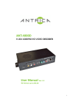
TECHNICAL MANUAL FOR
DVC-4000D CAMERAS
Manual Number: 86-4000-22
Release Date: June 23, 2009
1.
INTRODUCTION ...............................................................................................................4
2.
RECEIVING AND UNPACKING.....................................................................................5
3.
EQUIPMENT SUPPLIED..................................................................................................5
3.1.
3.2.
4.
IMPORTANT SAFETY INFORMATION REGARDING THE POWER SUPPLY ...............................5
OPTIONAL ITEMS ................................................................................................................5
INSTALLATION ................................................................................................................5
4.1. HOST COMPUTER REQUIREMENTS ......................................................................................5
4.1.1. Operating system:.......................................................................................................5
4.1.2. Hardware, Camera Link and Gigabit Ethernet configurations: ................................5
4.2. INSTALLING THE GIGABIT ETHERNET OR CAMERA LINK HOST INTERFACE BOARD ..........6
4.3. INSTALLING THE SOFTWARE ..............................................................................................6
4.4. INSTALLING THE CAMERA HARDWARE ..............................................................................6
5.
CAMERA FUNCTIONS.....................................................................................................6
5.1. OPERATING SPEED AND SINGLE/DUAL PORT OPTION .........................................................7
5.1.1. 20 MHz operation.......................................................................................................7
5.1.2. 40 MHz operation.......................................................................................................7
5.1.3. Single-port and dual-port options ..............................................................................7
5.2. OPERATIONAL MODES ........................................................................................................7
5.2.1. Continuous, overlapped exposure mode with electronic shuttering...........................7
5.2.2. Continuous, overlapped, extended-exposure mode ....................................................8
5.2.3. Edge-triggered exposure (single frame capture) mode ..............................................8
5.2.4. Bulb (pulse-width exposure) mode .............................................................................9
5.3. BINNING .............................................................................................................................9
5.4. REGION OF INTEREST .......................................................................................................10
6.
CCD PHENOMENA .........................................................................................................10
6.1.
6.2.
7.
BLOOMING .......................................................................................................................10
SMEAR ..............................................................................................................................10
MAINTENANCE ..............................................................................................................11
IMPORTANT WARRANTY INFORMATION .......................................................................11
7.1. CLEANING GUIDELINES....................................................................................................11
7.1.1. Cleaning the lens or optical assembly ......................................................................11
7.1.2. Standard (non-cooled) camera precautions .............................................................11
7.1.3. TE-Cooled camera precautions................................................................................11
7.1.4. Cleaning the infra-red filter (Standard and TE-Cooled Cameras) .........................12
7.1.5. Infra-red filter removal and installation...................................................................13
7.1.6. How to remove the IR filter ......................................................................................13
7.1.7. Cleaning the CCD faceplate.....................................................................................15
WARRANTY AND AFTER-SALE SERVICE .........................................................................16
8.
COPYRIGHT INFORMATION......................................................................................17
APPENDIX A: EXPOSURE TIMING DIAGRAMS................................................................18
2
APPENDIX B: DESCRIPTION OF DVC-4000D AUXILIARY AND POWER SUPPLY
CONNECTORS............................................................................................................................23
AUXILIARY CONNECTOR .............................................................................................................23
Auxiliary Connector Pin Signal list: .......................................................................................23
Pin 1, ENL...............................................................................................................................23
Pin 2, DIFF_RESET_OUT......................................................................................................23
Pin 3, TTL_RESET..................................................................................................................24
Pin 4, GND..............................................................................................................................24
Pin 5, ENF...............................................................................................................................24
Pin 6, STROBE (and programmable output) ..........................................................................24
POWER SUPPLY CONNECTOR PIN ASSIGNMENTS .........................................................................24
3
1.
Introduction
The DVC-4000D cameras are based on the Kodak KAI-04022 interline CCD, which provides
2048x2048 pixel resolution and 7.4 µm square pixels with high quantum efficiency and low noise. The
DVC-4000D is offered in both standard and cooled configurations, with a choice of Gigabit Ethernet or
Camera Link interface.
Additionally, the DVC-4000D is bundled with the full complement of DVC software. For developers,
DVC offers an intuitive and highly-functional software developer’s kit, which includes a comprehensive
API to streamline the integration of any DVC camera into your system. After software installation, the
SDK can be found in the /dvcco/docs directory.
For end-users, the DVCView imaging application provides full control of up to 8 cameras
simultaneously through an intuitive user interface, and it allows the user to acquire, pan, zoom, analyze,
and save imagery and metadata. DVCView also provides direct-to-disk video streaming, time-lapse
capture, image averaging, image background subtraction, and flat-fielding.
This manual is a functional overview of the camera, and it is intended to be a companion to the
DVCView User Manual and/or the SDK.
4
2.
Receiving and Unpacking
Your DVC-4000D camera was thoroughly tested and carefully packed at the factory. Once the camera
shipment is accepted for delivery, the carrier assumes full responsibility for its safe arrival. Should you
receive your shipment with any damage—concealed or apparent—please contact the carrier at once. The
carrier will instruct you on how to initiate a damage claim. If a visual inspection reveals damage upon
receipt, it must be noted on the freight bill or express receipt and the notation signed by the carrier’s
agent. Failure to do so can result in the carrier refusing to honor the claim.
To return your camera to DVC for service, you must first contact the DVC Customer Service
Department in the United States at 512-301-9564 and request a Return Material Authorization (RMA).
Returns will not be accepted without an RMA. See Section 0 for details.
3.
Equipment Supplied
The following is a list of equipment that may be supplied with the DVC-4000D camera, depending on
your order configuration:
•
•
•
•
•
•
DVC-4000D camera
Camera Link or Gigabit Ethernet host interface board
Camera Link or Gigabit Ethernet cable
Regulated power supply
Line cord with plug for country of service
DVC software CD
3.1.
Important safety information regarding the power supply
Dangerous voltage exists within the power supply. Do not tamper with or open the supply under
any circumstances. Doing so may expose lethal voltage to personnel and will void the warranty.
3.2.
Optional items
The following items may be ordered from authorized DVC dealers and are not typically supplied
with the camera:
• Lenses or other optical elements
• Third-party image analysis software.
4.
Installation
4.1.
Host computer requirements
4.1.1. Operating system:
Windows XP or Windows Vista
4.1.2. Hardware, Camera Link and Gigabit Ethernet configurations:
At least a 2 GHz Pentium 4 processor or equivalent, 2 GB RAM, 1 GB of free hard drive
space, an available slot for the interface board, and a graphics card with at least 128 MB
of video RAM and OpenGL ™ hardware support.
5
4.2.
Installing the Gigabit Ethernet or Camera Link host interface board
Follow the instructions included with the board
This host interface board contains sensitive electronic devices that can be damaged by static
discharge. Use appropriate static control methods when removing the board from the
antistatic shipping bag and when installing it into the host computer.
4.3.
Installing the Software
Place the DVC Software installation CD in the CD or DVD drive. Launch the installer, which
will guide each installation step.
4.4.
Installing the camera hardware
This camera contains sensitive electronic devices that can be damaged by static discharge.
Use appropriate static control methods when handling the camera. Avoid contact with
connector pins when cables and plugs are removed.
•
Mount the camera in the desired location
IMPORTANT: To avoid dust accumulation on the CCD sensor, do not remove the
protective lens mount cap until ready to mount the camera to the optical system. The
cap should be replaced whenever the camera is removed from the optical system
5.
•
Connect the 9-pin power supply connector to the back of the camera and secure it
with the thumbscrews, finger-tight
•
Connect the camera to the host with the supplied interface cable and secure it at both
ends.
•
Connect the power supply line cord to the mains
•
Switch on the power supply
Camera Functions
The DVC-4000D is a versatile, high-performance digital camera with functions tailored to scientific and
industrial markets. It is capable of both high-speed readout (40 MHz pixel rate) and low-noise readout
(20 MHz pixel rate), both at 12-bits. Readout can be configured for single-channel or dual-channel
operation. In the dual-channel mode, the KAI-04022 is split into two halves, which are read
simultaneously. This approximately doubles the frame rate of single-channel readout at a given
frequency.
The DVC-4000D has five basic operating modes described in detail below. Each mode can be operated
at either 20 or 40 MHz and can support binning and region of interest.
All operational modes are initiated by a trigger signal. In the case of continuous modes, the trigger
initiates the stream and the camera continues to run in streaming mode until explicitly disabled. The
edge-triggered, single-frame mode produces one exposure in response to the leading (default: falling)
edge of the trigger signal. Finally, in bulb mode, the camera exposes for the duration of the trigger pulse,
beginning on the leading (default: falling) edge and ending on the trailing edge. Readout occurs
immediately after the trailing edge.
The trigger signal can have three different sources: the external, TTL trigger via the auxiliary connector
(see appendix B), the software-controlled trigger via a hard-wired Camera Link camera control line, or
6
the software-controlled through camera trigger command, via the Camera Link serial port. Developers
should consult the DVC Camera API documentation for further information on the software-controlled
triggers.
If the TTL, external trigger is used, the trigger signal must be active-low. The trigger point is the high-tolow (leading edge) of the trigger signal.
5.1.
Operating speed and single/dual port option
The DVC-4000D is capable of operating at pixel rates of 20MHz and 40MHz and with single or
dual-port options as described above. All camera functions (e.g. exposure mode, binning, ROI,
etc.) are operational at either speed, subject to the limitations below.
5.1.1. 20 MHz operation
20MHz operation gives the user the maximum dynamic range, minimum noise floor,
and lowest-power operation. Dynamic range refers to the maximum signal swing under
which the camera meets performance specifications, and it is expressed in the maximum
number of captured electrons on the CCD. At 20MHz, the DVC-4000D is capable of
approximately 35,000 electrons dynamic range.
5.1.2. 40 MHz operation
40MHz operating speed provides the user with the highest capture frame rates at the
expense of slightly higher noise and power dissipation. Because of amplifier limitations
on the KAI-04022 CCD, the DVC-4000D is capable of approximately 20,000 electrons
dynamic range at 40 MHz.
5.1.3. Single-port and dual-port options
The DVC-4000D is capable of readout via a single port (all four million pixels read out
through a single 12-bit channel) or dual-port in which the image is split down the middle
in the “slow scan” direction and each half is read out simultaneously, using two 12-bit
channels. The port options are available in both 20 MHz and 40 MHz, and for all
operational modes. Dual-port operation can result in slight signal mismatch between the
two image halves, due to differences in the signal path components. This can be easily
compensated in most applications.
5.2.
Operational modes
The following section describes the distinct operating modes of the DVC-4000D cameras. Users
of DVCView software will find many of these modes seamlessly integrated together to make
operation of the camera as easy as possible. However, developers have full control of these
modes via the DVC camera API.
Refer to Appendix A for exposure timing diagrams.
5.2.1. Continuous, overlapped exposure mode with electronic shuttering
This mode operates the CCD in a “video” mode, in which the previous exposure is being
read out while the current exposure is underway. Once initiated via trigger, the camera
operates continuously in this fashion until halted by the host computer.
Exposure is controlled using “electronic shuttering.” Depending on the exposure setting,
electronic shuttering inhibits the CCD exposure during a specific portion of the readout
interval. Referring to the first figure in appendix A, the shorter the desired exposure, the
7
longer the inhibition of exposure during the readout of the previous frame. Regardless of
exposure time, frame rate remains constant. The maximum exposure time in this mode is
the time required to read out one frame, and that frame time depends on the pixel rate,
ROI, and binning settings.
Exposure range (full-resolution—without binning or Region-of Interest):
20MHz Single-Tap Readout: Increments of 111.5 microseconds, ranging from 111.5
microseconds to 230 milliseconds.
20MHz Dual-Tap Readout: Increments of 60 microseconds, ranging from 60
microseconds to 123 milliseconds.
40MHz Single-Tap Readout: Increments of 58.5 microseconds, ranging from 58.5
microseconds to 121 milliseconds.
40MHz Dual-Tap Readout: Increments of 33 microseconds, ranging from 33
microseconds to 67 milliseconds.
5.2.2. Continuous, overlapped, extended-exposure mode
In this mode, exposure and readout are overlapped, but the exposure ranges from one
frame-time (time taken to read out entire frame) to many seconds. This mode is typically
used if intermediate exposure times are desired but with the fastest frame rate possible.
Once initiated via trigger, the camera operates continuously in this fashion until it is
halted by the host computer.
Exposure range (full-resolution— without binning or Region-of Interest):
20MHz Single-Tap Readout: Increments of 111.5 microseconds, ranging from 230
milliseconds to 2 hours.
20MHz Dual-Tap Readout: Increments of 60 microseconds, ranging from 123
milliseconds to 1 hour.
40MHz Single-Tap Readout: Increments of 58.5 microseconds, ranging from 121
milliseconds to 1 hour.
40MHz Dual-Tap Readout: Increments of 33 microseconds, ranging from 67
milliseconds to 35 minutes.
5.2.3. Edge-triggered exposure (single frame capture) mode
Edge-triggered exposure mode enables the camera to initiate an exposure immediately
upon the leading (falling) edge of the external or Camera Link control lines, with an
exposure time set by software. Alternatively, the exposure can be initiated by the host
via the DVC API. The exposure and readout sequence is the same as the nonoverlapped, continuous mode and has the same exposure range, except only one frame is
generated. Once the readout of that frame has finished, the camera returns to the armed
state, awaiting the next trigger edge.
8
If subsequent trigger pulses occur faster than the combined exposure and readout time,
any trigger received during the exposure or readout time will be ignored, as illustrated in
appendix A.
Exposure range (full-resolution— without binning or Region-of Interest):
20MHz Single-Tap Readout: Increments of 111.5 microseconds, ranging from 111.5
microseconds to 2 hours.
20MHz Dual-Tap Readout: Increments of 60 microseconds, ranging from 60
microseconds to 1 hour.
40MHz Single-Tap Readout: Increments of 58.5 microseconds, ranging from 58.5
microseconds to 1 hour.
40MHz Dual-Tap Readout: Increments of 33 microseconds, ranging from 33
microseconds to 35 minutes.
5.2.4. Bulb (pulse-width exposure) mode
The term “bulb” mode is borrowed from photography, denoting a camera setting in
which the shutter stays open as long as the shutter button is depressed. Bulb mode in the
DVC-4000D is analogous in that the CCD exposes as long as the trigger signal is
asserted (a low logic level on the external trigger or a low command on the Camera Link
CC1 control line). Upon the rising edge of the trigger signal, readout of the exposure is
initiated. Maximum exposure time is indefinite, although dark current will set the
practical exposure time limit, depending on the operating temperature and the tolerance
of the application to dark current pattern noise.
Exposure range:
20MHz or 40MHz Readout: 5 microseconds minimum. Maximum limited by dark
current and particular application.
5.3.
Binning
Binning is the process of summing adjacent lines and/or pixels in order to increase dynamic
range, sensitivity, or both. Binning can either be accomplished on the CCD itself by summing
the collected charge (on-chip binning) or in software, after A/D conversion. On-chip binning can
result in slightly lower noise relative to software binning, under certain circumstances. Because
fewer lines are actually read out when binning vertically, on-chip binning in the vertical
direction can produce a significant increase in frame rate with increasing binning ratios.
However, because the clocking cannot be accelerated in the horizontal direction, horizontal
binning provides no such speed increase.
In all modes of operation, the DVC-4000D is capable of arbitrary on-chip binning (2x, 3x, 4x,
5x…21x,…) in the vertical direction, and 2x, 3x, and 4x on-chip binning in the horizontal
direction. As vertical binning increases, anti-blooming control decreases, so the user must
control image illumination more carefully while binning. However, blooming does not cause any
damage to the camera.
As the binning factor increases, the CCD vertical registers are driven faster. This naturally
causes more heating of the CCD and driving electronics. Since dark current generation increases
9
with CCD die temperature, a noticeable increase in CCD dark current can occur at very high
binning factors.
5.4.
Region of Interest
Arbitrary, on-chip vertical Region of Interest (ROI) is fully supported on the DVC-4000D
cameras. When ROI is enabled, the regions above and below the region of interest are “dumped”
as fast as the CCD allows. The region of interest itself is read out normally. Dumping unwanted
lines outside the ROI can significantly increase the readout rate of the camera. DVCView
software provides interactive, graphical ROI selection, and the DVC camera API provides
developers with full ROI control. On-chip horizontal ROI is not available. Simultaneous binning
and ROI is fully supported.
As in binning, the CCD vertical registers are driven faster when the region of interest is reduced.
Dark current can increase during operation with small regions of interest.
6.
CCD phenomena
The Kodak KAI-04022 CCD is a high-performance image sensor with very good characteristics over a
wide operating range. To be as versatile as possible, the DVC-4000D camera exploits as much of the
CCD capability as possible and provides the user a great degree of control over the CCD functions. As a
result, it is possible to observe some interesting, low-level CCD phenomena under certain extreme
conditions.
6.1.
Blooming
Blooming is the result of charge spillover in the vertical transfer regions when the signal greatly
exceeds saturation. The DVC-4000D provides anti-blooming control, which suppresses
blooming under most imaging conditions. If signal levels are extreme and such high signal levels
cover a large percentage of the field of view, blooming may occur. The result is jagged, vertical
bright streaks running below such regions. In general, anti-blooming performance decreases with
increasing binning ratios.
6.2.
Smear
Smear is inherent to interline CCD sensors such as the KAI-04022. It is the result of transferring
image charge out of the pixels and into the adjacent vertical charge-transfer registers while
photons strike the CCD. Though the vertical charge-transfer registers are covered with a light
shield, unwanted signal can be introduced into them either by small amounts of light leaking
under the light shield or by signal electrons diffusing into the transfer region from the adjacent
pixels.
Smear is typically noticed during very short exposure times, when an extremely high light
intensity is incident on the CCD. The result is regions of elevated signal level extending above
and below very bright regions. Kodak interline CCDs exhibit very low smear levels, and smear
should not be noticeable under normal operating conditions.
10
7.
Maintenance
IMPORTANT WARRANTY INFORMATION
There are no user-serviceable parts inside the camera. Removing the rear cover of the camera
without express authorization from DVC Company will void the camera warranty.
DVC professional cameras are manufactured in a clean environment. Before shipping, each camera is
tested to assure that it meets stringent specifications for cleanliness and quality.
7.1.
Cleaning Guidelines
Frequent lens changes, especially without careful attention to contaminants, can allow debris to
accumulate on the infra-red blocking filter and lens surfaces. Therefore, DVC Company
provides the following guidelines for cleaning those components.
To minimize the need to clean the optical surfaces, do not remove the protective lens mount cap
shipped with the DVC-4000A camera until you are ready to mount the camera to the optical
system.
7.1.1. Cleaning the lens or optical assembly
Please follow the lens manufacturer’s recommendations for cleaning. DVC Company is
not responsible for any damage caused to a lens or optical assembly caused by customer
cleaning or misuse.
To ensure optimum image quality with any DVC camera, do not remove the protective
lens-mount cap until ready to mount the camera on the application. If the camera is
removed from the application, immediately replace the cap. Doing so will keep dust and
other contaminants from accumulating on the optical surfaces. In addition, please note
the following model-specific guidelines.
7.1.2. Standard (non-cooled) camera precautions
While the lens mounting ring and locking flange allow the user some lens back-focus
adjustment, complete removal of the ring will expose the CCD faceplate and will likely
cause debris to accumulate on its surface. Extreme care should be taken to avoid
completely removing the lens mounting ring and exposing the CCD faceplate unless
absolutely necessary. Fingerprints or other evidence of contact with the CCD
faceplate may void the warranty.
7.1.3. TE-Cooled camera precautions
The DVC Thermoelectrically-cooled cameras contain the CCD in a sealed, gas-filled
chamber having an anti-reflective glass window. Do not, under any circumstances,
loosen or remove the inner glass window from a cooled camera. Doing so will void
the warranty. If it is suspected that the seal has been broken or if the window breaks, call
DVC Customer Service. Do not apply power to the camera. Moisture will have been
introduced into the chamber, and cooling in the presence of moisture will cause
condensation and frost on the CCD, which can damage the entire cooling unit.
11
7.1.4. Cleaning the infra-red filter (Standard and TE-Cooled Cameras)
The infra-red filter is visible when the lens is removed, mounted inside the lens
mounting ring. This filter blocks invisible, near-infra-red light from reaching the CCD
sensor. This is desirable in most applications where the camera is imaging in the visible
spectrum.
7.1.4.1. What must I do before cleaning the infra-red filter?
Do not remove the filter from the camera.
First, remove the lens and carefully examine the filter in a clean location
under a strong, direct light. Try to determine if the contaminants are a few
dust particles, oily smudge (such as fingerprints) or both.
7.1.4.2. What if the contamination is only a few dust particles?
Use a CLEAN, DRY (preferably brand-new), camel hair lens cleaning brush
(such as those used by photographers) to gently wipe the particles off of the
filter.
7.1.4.3. What if the contamination includes a smudge?
The filter is a high-quality, coated optical component and should be treated
with extreme care. Scratches, chemical contamination, or other damage due to
improper cleaning may void the warranty.
•
Remove the camera from the optical assembly and bring the camera to a clean,
dry location where it is safe to use flammable solvents (please see caution
below)
•
Carefully loosen the lens mount lock ring using the supplied DVC lock ring
wrench.
•
Orient the camera so that the lens mount is pointing downward and carefully
unscrew the lens mounting ring and integral filter.
•
Place the camera face down on a clean, dry surface to prevent particles from
accumulating on the CCD faceplate.
•
Once the filter is removed, Use a CLEAN, DRY (preferably brand-new), camel
hair lens cleaning brush (such as those used by photographers) to gently wipe
the particles off of the filter.
•
Re-examine the filter after removing the dust. If a smudge is still visible,
proceed by dipping a clean, lint-free cotton swab in ethyl or isopropyl alcohol.
The swab should be saturated, but not dripping.
•
Carefully draw the swab once across the surface, then rotate the swab 180
degrees to expose the fresh surface and draw it across the filter surface again. Be
careful not to pool alcohol on the glass surface.
•
Re-examine once again and repeat the process once, if necessary.
12
If contamination continues to be a problem, please call DVC Customer
Service for assistance.
Caution: ethyl and isopropyl alcohols are highly flammable! Do not use
near extreme heat, arcing electrical equipment (such as space heaters) or
open flame! Use only with proper ventilation. Follow all safety
instructions provided by the manufacturer of the alcohol product.
7.1.5. Infra-red filter removal and installation
If greater near-infra-red sensitivity is desired, the infra-red filter can be removed. It is
important to note that removal of the IR filter can allow debris to collect on the CCD
faceplate. Please use every precaution to avoid contact with the CCD faceplate and to
keep the camera securely mounted to the optical system or capped when not in use.
7.1.6.
How to remove the IR filter
Caution: This procedure will cause the focus calibration to be lost. Readjustment of the
lens back-focus will be required after reassembly
Loosen the lens mount lock ring with the wrench supplied by DVC
Unscrew the lens mount/filter assembly ring from the camera body and remove the lock
ring from the lens mount ring
Hold the lens cap with the pins sticking upward in one hand
Lower the lens filter assembly on to the pins with the other hand
13
Hold the lens cap and rotate the lens ring anti-clockwise and then remove the lens ring.
Remove the filter from the filter ring with lens tissue and store in a protective container
Replace the lens ring on to the filter ring and screw on clockwise
Remove the lens ring from the lens cap
14
Screw the lock ring back onto the lens mount ring and screw both back onto the camera.
Adjust focus by loosening the lock ring and rotating the lens mount ring to adjust the
lens-to-CCD distance.
To re-install the IR filter or other filters, reverse the above procedure.
7.1.7.
Cleaning the CCD faceplate
CAUTION: The CCD faceplate is a high-quality, coated optical surface and
should only be cleaned by authorized, DVC personnel.
If contamination of the CCD faceplate is suspected, DVC strongly
recommends returning the camera to the factory for professional cleaning.
Scratches, chemical contamination, or other damage due to improper
cleaning may void the camera warranty.
15
Warranty and After-Sale Service
DVC Company warrants equipment manufactured to be free from defects of material and workmanship.
Any part or parts will be repaired or replaced when proven by DVC examination to have been defective
within two years from the date of shipment to the original purchaser. Any warranty repairs will be
performed at the factory or as otherwise authorized by DVC, in writing. Transportation charges to DVC
shall be pre-paid by purchaser.
This warranty does not extend to DVC manufactured equipment subjected to misuse, accident, neglect or
improper application. Nor does the warranty extend to DVC manufactured equipment that is repaired or
altered by anyone other than DVC or those authorized by DVC, in writing. Products manufactured by
other companies, but re-sold by DVC such as lenses, optical and electro-optical assemblies, power
supplies, cables, image processor boards and software are warranted by the original manufacturer.
This warranty is in lieu of all other warranties expressed or implied. DVC shall not be liable for any
collateral or consequential damages.
A Return Material Authorization (RMA) Number must be obtained from DVC prior to returning any
item for warranty repair or replacement.
16
8.
Copyright Information
Copyright © 2008 DVC Company. All rights reserved.
Copyright on this document is owned by DVC Company, 10200 Highway 290 West, Austin, Texas
78736
The information contained in this document is proprietary to DVC Company. Information in this
document may be used for non-commercial, personal and educational information purposes only, and
may be viewed, copied, printed and distributed only in accordance with these terms and conditions of
use. This information may not be copied nor duplicated in any form, in whole or in part, for use for profit
or another business. All printouts, copies or reproductions of all or any part of the information contained
in this document must include all patent, copyright and/or trademark notices originally included with the
information. User obtains no rights in the information or in any product, process, technology or
trademark which it includes or describes, and is expressly prohibited from modifying the information or
creating derivative works without the express written consent of DVC Company. DVC models
represented in photographs may differ slightly from products shipped due to continuing product
improvements and variations. DVC reserves the right to make changes to product specifications and
documentation at any time without notice. The information in, or references from, this document are
believed to be accurate and reliable, however, no responsibility is assumed by DVC for its use. DVC
reserves the right to change, modify or correct the information contained in this document at any time
without notice. While DVC has used all reasonable efforts to indicate and to supply information
regarding trademarks used in this publication, the absence of a trademark identifier is not a
representation that a particular mark is not a trademark. All non-DVC products, brand names, company
names are trademarks or registered trademarks of their respective owners, and appear in this document
for reference only.
Disclaimer: The information in this document is provided "as is." DVC expressly disclaims all
representations and warranties of any kind regarding the contents or use of the information including, but
not limited to, express and implied warranties of accuracy, completeness, merchantability, fitness for a
particular use, or non-infringement. In no event will DVC be liable for any direct, indirect, special,
incidental or consequential damages, including lost profits, lost business, or lost data, resulting from the
use or reliance upon the information, whether or not DVC has been advised of the possibility of such
damages.
17
Appendix A: Exposure Timing Diagrams
Continuous, overlapped exposure mode with electronic shutter
In the continuous, overlapped exposure mode, the camera remains in an idle state until the falling edge
of the trigger. A first exposure is made, followed by the typical, interline CCD overlapped
exposure/readout cycle. Electronic shuttering allows the exposure to be adjusted via software control
without altering the frame rate of the readout. Any further triggers while the camera is operating
continuously are ignored. The camera will remain in this continuous operation until disabled through
software command. It can then be re-armed for another trigger event.
trigger ignored until camera operation halted
software
command
or
external trigger
(TTL_RESET)
exposure
exposure
texp
exposure
Treadout
exposure
Treadout
strobe
(output)
ENF
(output)
image data
(output)
Pixel clock runs continuously
Continuous, overlapped exposure mode with electronic shutter. Strobe pulse occurs only if enabled.
18
Continuous, overlapped, extended-exposure mode
This mode is similar to the overlapped, electronic-shuttered exposure mode except that the electronic
shutter is not enabled and the exposure times are greater than one readout cycle (frame time). As a result,
readout frame rate will decrease as exposure time is increased, but the overlapping exposure and readout
provide the maximum frame rate for a given exposure time. This mode also offers much longer
integration times than overlapped, electronic-shuttered exposure mode.
Any further triggers while the camera is operating continuously are ignored. The camera will remain in
this continuous operation until disabled through software command. It can then be re-armed for another
trigger event.
trigger ignored until camera operation halted
software
command
or
external trigger
(TTL_RESET)
exposure
exposure
exposure
texp
texp
exposure
texp
Treadout
strobe
(output)
ENF
(output)
image data
(output)
Pixel clock runs continuously
Continuous, overlapped, extended exposure mode. Strobe pulse is disabled due to continuous nature of exposure
19
Continuous, non-overlapped exposure mode
This mode is similar to the overlapped exposure mode except that the exposure and readout periods are
separate and do not overlap. As a result, for a given exposure time, readout frame rates will be lower
than that of overlapped exposure and will also decrease as exposure time is increased. Any further
triggers while the camera is operating continuously are ignored. The camera will remain in this
continuous operation until disabled through software command. It can then be re-armed for another
trigger event.
trigger ignored until camera operation halted
software
command
or
external trigger
(TTL_RESET)
exposure
exposure
exposure
texp
Treadout
strobe
(output)
ENF
(output)
image data
(output)
Pixel clock runs continuously
Continuous, non-overlapped exposure mode. Strobe pulse occurs only if enabled.
20
Edge-triggered exposure (single frame capture) mode
Edge-triggered exposure mode operates almost identically to the first frame of the non-overlapped
continuous mode except that instead of continuing to run, the camera returns to the armed state, waiting
for another trigger. Exposure is controlled by software.
trigger ignored during exposure and readout
software
command
or
external trigger
(TTL_RESET)
exposure
exposure
exposure
texp
Treadout
strobe
(output)
ENF
(output)
readout
image data
(output)
Pixel clock runs continuously
Edge-triggered exposure mode. Strobe pulse occurs only if enabled.
21
Bulb (pulse-width exposure) mode
Bulb mode allows the camera exposure to be controlled by the external trigger signal. The leading edge
of the trigger signal initiates the exposure, and the camera will continue to expose until the trailing edge
of the trigger, as shown. The readout sequence begins immediately after the trigger signal trailing edge,
and at the end of readout, the camera returns to the armed state, awaiting the next trigger. Any trigger
activity during the readout sequence is ignored.
trigger ignored until readout complete
software
command
or
external trigger
(TTL_RESET)
exposure
exposure
exposure
texp
Treadout
strobe
(output)
ENF
(output)
image data
(output)
Pixel clock runs continuously
Bulb (pulse-width exposure) mode. Strobe pulse occurs only if enabled.
22
Appendix B: description of DVC-4000D auxiliary and power supply
connectors
Auxiliary connector
The auxiliary connector on the DVC-4000D camera allows the user access certain camera
control and internal status signals. The following section describes each signal.
Illustration of the auxiliary connector on the rear of the DVC-4000D camera
Auxiliary Connector Pin Signal list:
Pin #
Signal
-----------------1
ENL (Output)
2
DIFF_RESET_OUT (Output)
3
TTL_RESET (Input)
4
GND
5
ENF (Output)
6
STROBE/INT-PULSE (Output)
Pin 1, ENL
ENL refers to “Enable Line.” It is an active-high TTL signal and is asserted during the
valid pixel period on each line, as shown in the diagrams in Appendix A. It returns low
during the inter-line period between each line and during the inter-frame period between
each frame.
Pin 2, DIFF_RESET_OUT
This pin is an active-low TTL signal that is the buffered version of the Camera Link
CC1 signal. The CC1 signal, driven from the host, is one of the software-controlled
23
trigger signals for the camera as described in Appendix A. The CC1 signal is brought
out of the camera as DIFF_RESET_OUT to allow users to trigger other devices.
DIFF_RESET_OUT is labeled INPUT_1 on older DVC cameras and on the Mini-DINto-BNC cable accessory sold by DVC.
Pin 3, TTL_RESET
TTL_RESET is a TTL input used to trigger exposures. It functions identically to the
Camera Link CC1 signal. TTL_RESET is also labeled VRST_INT on older DVC
cameras and on the Mini-DIN-to-BNC cable accessory sold by DVC.
Pin 4, GND
This is the electrical ground for the camera.
Pin 5, ENF
ENF refers to Enable Frame and is a TTL output that is high during active readout lines.
EN_FRAME remains high throughout the active readout and returns low between
frames.
Pin 6, STROBE (and programmable output)
STROBE is a TTL output that, if enabled, is high during the actual sensor exposure time
in certain modes. Refer to the diagrams in Appendix A for details on STROBE operation
with respect to the exposure interval in each mode. STROBE is typically used to
synchronize an external flash lamp or other device with the camera.. The STROBE
signal can also be configured as a programmable output that can be set high or low from
the host computer. Refer to the DVC API documentation for details.
Power supply connector pin assignments
The power supply connector is a standard, DB-9 male connector with the following pin
assignments:
Pin No.
6
7
8
9
Signal Name
GND
Reserved
GND
Reserved
24
Signal Name
+5 VDC, 250mA
+5 VDC, 1250mA
-15 VDC, 250mA
Reserved
+15 VDC, 250mA
Pin No.
1
2
3
4
5