1
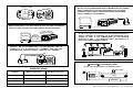
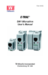
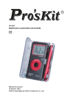
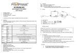
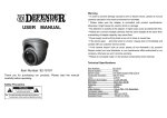
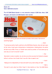
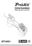
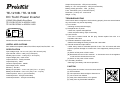
TE-1210B / TE-1410B
DC To AC Power Inverter
1000W 50Hz Modify Sine Wave
TE-1210B: DC12V to AC220V~240V
TE-1410B: DC24V to AC220V~240V
AC OUTPUT
LOW
NORMAL BATTERY
REMOTE
CONTROL
ON
AC
OUTLET
OVER
LOAD
OVER
TEMP
OFF
LOAD
Instruction Manual
Please read user manual before use.
USEFUL APPLICATIONS
Run notebook computers,radios,TVs,VCRs,Lamps,Fans,Fax,Drill….etc.
SPECIFICATION
Input voltage range : DC 10~15V (12V) // DC 20~30V (24V)
Input full load current : 100A (12V) // 50A (24V)
Standby input current : <0.6A (12V) // <0.5A (24V)
Output voltage (AC) : 220V~240V
Output waveform : modify sinewave
Output frequency : 50Hz
Continue output power : 1000W
Peak output power : 2400W
Efficiency : 85~90%
Battery low pre-alarm : 10.5 ± 0.5V (12V) // 21 ± 1V (24V)
Battery low shutdown : 9.5 ± 0.5V (12V) // 19 ± 1V (24V)
Thermal protect : 60 ± 5℃(microcontroller)
Overload protect : YES (microcontroller)
Overload protection : YES (microcontroller)
Output short protection : YES (microcontroller)
Battery ex. 12V / 24V protection : YES (microcontroller )
Battery polarity protection : YES (by fuse )
Fuse : 20A*6PCS (12V) // 10A*6PCS (24V)
Dimension ( L*W*H) mm : 340*135*79
Weight : 2.5 kg
TROUBLESHOOTING
If the inverter does not appear to be functioning properly, there are several reasons
why the inverter may not be responding.
1) Poor contact
*Cleaning contact parts thoroughly.
2) Receptacle has no power
*check fuse, replace damaged fuse.
*check receptacle wiring. repair if necessary
3) Fuse is blown
*The fuse is located inside the DC plug. Please replace fuse with a new
equivalent value fuse.
4) Overload caused AC output reduce
*Reduce the wattage of loading to lower than 1000 watts.
5) Thermal caused AC output reduce
*Under heavy loads for extended periods of time. The AC inverter will reduce
output to prevent damage to excess heat. If this happened, please proceed as
below:
(A) Switch off the power of this inverter.
(B) Decreases the load of this machine i. e. disconnect some of the appliances
or wait until this inverter become cool.
(C) Switch on the power of this inverter.
6) Low-battery shutdown
*Recharge your battery and resume operation.
CAUTION
Always place the inverter in an environment which is:
(A) well ventilated
(B) not exposed to direct sunlight or heat source
(C) out of reach from children
(D) away from water/moisture, oil or grease
(E) away from any flammable substance
AC OUTPUT SOCKET
FAN
AC OUTPUT
FAN
WARNING:DC INPUT
DO NOT REVERSE INPUT
LOW
NORMAL BATTERY
REMOTE
CONTROL
ON
AC
OUTLET
OVER
LOAD
DO NOT USE THE INVERTER BEYOND ITS MAXIMUM OUTPUT POWER.
WHEN CONNECTED TO ANY APPLIANCE MAKE SURE THE TOTAL
STARTING POWER CAPACITY DOES NOT EXCEED THE MAXIMUM
OUTPUT POWER OF THE INVERTER.
OVER
TEMP
OFF
LOAD
(+)
(-)
POWER SWITCH
AC OUTPUT
TERMINAL
TERMINAL
LOW
NORMAL BATTERY
REMOTE
CONTROL
ON
OVER
LOAD
OVER
TEMP
BATTERY
OFF
WHEN CONNECTED TO ANY APPLIANCE, BE SURE TO TURN ON INVERTER
FIRST. AND THEN TURN ON THE POWER SWITCH OF THE APPLIANCE.
TURN ON FIRSTLY
TELEVISION
AC OUTPUT
TURN ON
SECONDLY
LOW
NORMAL BATTERY
REMOTE
CONTROL
ON
OVER
LOAD
OVER
TEMP
OFF
IF THE TOTAL WATTS OF ELECTRICAL APPLIANCES EXCEEDS THE
OUTPUT CAPACITY OF INVERTER. OR AFTER OPERATING FOR A
PERIOD OF TIME. IF THE TEMPERATURE OF THE INVERTER
REACHES 60 DEG C, THE INVERTER SHALL BE REDUCED AC
OUTPUT BY THE PROTECTION CIRCUIT.
0
60 C
CAUTION : DO NOT REVERSE INPUT. USE RED BATTERY CORD TO
CONNECT (+) OF A DC BATTERY TO (+) TERMINAL. AND THEN, USE
BLACK BATTERY CORD TO CONNECT (-) BATTERY TO (-) TERMINAL.
.
RED
BLACK
BATTERY
※WARNING※FLUORESCENT LAMP
DO NOT USE THIS DEVICE WITH FLUORESCENT LAMPS.
WARNING SIGNAL
Glow switch
Condition
Warning signal cycle
Shutdown signal cycle
a
AC IN
Low battery alarm:
BI BI BI (pause)
BEE BEE BEE (pause)
Over heating alarm:
BI BI (pause)
BEE BEE (pause)
Over load alarm:
BI BI BI BI BI BI
Continuous tone
b
Lamp
Power Factor
Capacitor
BALLASTS
Note: BI is a short beep, and BEE is a longer beep.
©2014 Copyright by Prokit’s Industries Co., Ltd. All right reserved.