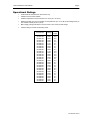
1
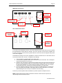
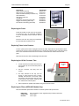
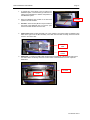
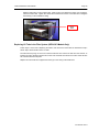
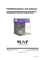
PCR Workstations and Cabinets Installation and User Instructions UVP, LLC 2066 W 11th Street, Upland, CA 91786 Tel: (800) 452-6788 / (909) 946-3197 Fax: (909) 946-3597 Ultra-Violet Products Ltd. Unit 1, Trinity Hall Farm Estate Nuffield Road Cambridge CB4 1TG UK Tel: +44(0)1223-420022 / Fax: +44(0)1223-420561 Web Site: www.uvp.com 81-0357-01 Rev A PCR Workstations and Cabinets Page 2 Introduction The UV1 and UV2 PCR Hoods create an ideal environment for preparing PCR and other samples by reducing the chance of contamination. The built-in high intensity shortwave (254nm) UV provides a source for inactivation of DNA between experiments. Additional contamination control is provided by the specially-coated stainless steel and aluminum design that maintains antimicrobial ® efficacy. The surface resists growth of destructive bacteria, molds and fungi. The Makrolon panel assembly blocks UV below 400nm. In addition to the UV1/UV2 PCR Hood features, HEPA/UV3 PCR Hoods provide additional protection by blowing filtered air, treated by the HEPA/UV system, into the PCR chamber. The UV/Air Circulator, included as standard on UV2 and HEPA/UV3 PCR Hoods and optional on the UV1 PCR Workstation (95-0367-xx only), eliminates amplicons of DNA or genomic DNA from a previously-dispensed experiment. For ordering information, refer to the “Maintenance and Replacement Parts/Accessories” section. Safety Information The PCR Hoods are designed with functionality, reliability and safety in mind. The Hoods provide shortwave (254nm) UV which is a powerful source of UV radiation that will cause damage to unprotected eyes and skin. Before operating, ensure that all personnel are properly protected and that the instructions for the use of this equipment are followed. A safety shut-off switch automatically turns ® off the UV light when the door is open, protecting users from UV exposure. In addition, the Makrolon panels are specially formulated to block UV wavelengths below 400nm. Disconnect the power supply before assembling or servicing the PCR Hoods. Specifications STANDARD UV (UV1 and UV2) PCR MODELS UV1 PCR Cabinet 95-0437-01 (115V) 95-0437-02 (230V UK) 95-0437-04 (230V Euro) 95-0437-03 (100V) 95-0437-05 (230V Denmark) Light Sources: 254nm 8-watt UV: Chamber White 8-watt Chamber UV2 PCR Cabinet 95-0436-01 (115V) 95-0436-02 (230V UK) 95-0436-04 (230V Euro) 95-0436-03 (100V) 95-0436-05 (230V Denmark) Light Sources: 254nm 8-watt UV: Chamber UV/air circulator White 8-watt: Chamber UV1 PCR Workstation 95-0367-01 (115V) 95-0367-02 (230V UK) 95-0367-04 (230V Euro) 95-0367-03 (100V) 95-0367-05 (230V Denmark) Light Sources: 254nm 25-watt UV: Chamber White 15-watt: Chamber Features include: Two power outlets Two small shelves UV Timer Antimicrobial coated stainless steel (work surface) & aluminum ® Makrolon panels block below 400nm Features include: Two power outlets Two small shelves UV Timer Antimicrobial coated stainless steel (work surface) & aluminum ® Makrolon panels block below 400nm UV/Air Circulator Dimensions: Exterior: 28.7H x 21.4W x 24D in. (729 x 544 x 610 mm) Interior: 19.7W x 21.4D in. (500 x 544 mm) Features include: Four power outlets Two shelves UV Timer Antimicrobial coated stainless steel (work surface) & aluminum ® Makrolon panels block below 400nm Optional: UV/Air Circulator Dimensions: Exterior: 28.7H x 29W x 24D in. (729 x 737 x 610 mm) Interior: 27.8W x 21.4D in. (706 x 544 mm) Dimensions: Exterior: 28.7H x 21.4W x 24D in. (729 x 544 x 610 mm) Interior: 19.7W x 21.4D in. (500 x 544 mm) UV2 PCR Workstation 95-0439-01 (115V) 95-0439-02 (230V UK) 95-0439-04 (230V Euro) 95-0439-03 (100V) 95-0439-05 (230V Denmark) Light Sources: 254nm 25-watt UV: Chamber 254nm 8-watt UV: UV/air circulator White 15-watt: Chamber Features include: Four power outlets Two shelves UV Timer Antimicrobial coated stainless steel (work surface) & aluminum ® Makrolon panels block below 400nm UV/Air Circulator Dimensions: Exterior: 28.7H x 29W x 24D in. (729 x 737 x 610 mm) Interior: 27.8W x 21.4D in. (706 x 544 mm) 81-0357-01 Rev A PCR Workstations and Cabinets Page 3 HEPA/UV3 PCR MODELS HEPA UV3 PCR Cabinet HEPA UV3 PCR Workstation 95-0434-01 (115V) 95-0434-02 (230V UK) 95-0434-04 (230V Euro) 95-0434-03 (100V) 95-0434-05 (230V Denmark) Light Sources: 254nm 8-watt UV: Filter area Chamber UV/air circulator White – 8-watt: Chamber Three stage filters: Pre-filter Carbon filter HEPA filter Features include: Two power outlets Two small shelves UV Timer Antimicrobial coated stainless steel (work surface) and aluminum ® Makrolon panels block below 400nm UV/Air Circulator 95-0438-01 (115V) 95-0438-02 (230V UK) 95-0438-04 (230V Euro) 95-0438-03 (100V) 95-0438-05 (230V Denmark) Light Sources: 254nm UV: Filter area 8-watt Chamber 25-watt UV/air circulator 8-watt White – 8-watt: Chamber Three stage filters: Pre-filter Carbon filter HEPA filter Features include: Four power outlets Two shelves UV Timer Antimicrobial coated stainless steel (work surface) and aluminum ® Makrolon panels block below 400nm UV/Air Circulator Dimensions: Exterior: 32.5H x 21.4W x 24D in. (826 x 544 x 610 mm) Interior: 19.7W x 21.4D in. (500 x 544 mm) Dimensions: Exterior: 32.5H x 29W x 24D in. (826 x 737 x 610 mm) Interior: 27.8W x 21.4D in. (706 x 544 mm) Shelves Construction Dimensions (Workstation) Dimensions (Cabinet) Two - Formed antimicrobial-coated aluminum 13”W x 4.2”D (330 x 107mm) 8.75” x 4”D (222 x 102mm) Construction Interior Exterior Door and Side Panels Antimicrobial coated stainless steel (horizontal work surface) and aluminum Aluminum powder coated ® Makrolon panel assembly Blocks UV under 400nm Electrical 115V - 60 Hz, 230V - 50 Hz, 100V - 50/60Hz 81-0357-01 Rev A PCR Workstations and Cabinets Page 4 Operational Ratings • PCR Hoods are intended to be used indoors only • Altitude must not exceed 2,000m • Ambient temperature must not exceed 5°C to 40°C (41°F to 104°F) • Relative humidity must not exceed 80% for temperatures up to 31°C (88°F) decreasing linearly to 50% relative humidity at 40°C (104°F) • Mains supply voltage fluctuations must not exceed ±10% of the nominal voltage • Pollution rating 2 or better for laboratory areas Part Number Voltage Max Amps 95-0437-01 95-0437-02 95-0437-04 95-0437-03 95-0437-05 95-0436-01 95-0436-02 95-0436-04 95-0436-03 95-0436-05 95-0367-01 95-0367-02 95-0367-04 95-0367-03 95-0367-05 95-0439-01 95-0439-02 95-0439-04 95-0439-03 95-0439-05 95-0434-01 95-0434-02 95-0434-04 95-0434-03 95-0434-05 95-0438-01 95-0438-02 95-0438-04 95-0438-03 95-0438-05 115V 230V 230V 100V 230V 115V 230V 230V 100V 230V 115V 230V 230V 100V 230V 115V 230V 230V 100V 230V 115V 230V 230V 100V 230V 115V 230V 230V 100V 230V 9.1 8.8 8.8 9.1 8.8 9.1 8.7 8.7 9.1 8.7 8.8 8.6 8.6 8.8 8.6 9.1 8.7 8.7 9.1 8.7 9.1 8.7 8.7 9.1 8.7 9.1 8.7 8.7 9.1 8.7 81-0357-01 Rev A PCR Workstations and Cabinets Page 5 Assembling the PCR System Carefully remove the PCR Hood components from the packaging. CAUTION: Use care when unboxing the PCR Hood, as staples with sharp ends may have been used in packaging. Follow the assembly instructions provided in this manual. NOTE: Place the PCR Hood Base on a level surface large enough to accommodate the entire Base. The surface must be level to ensure ® proper alignment of the Makrolon panels. Required Tools • Philips head screwdriver (motorized, if available) • Flathead screwdriver (motorized, if available) • Gloves, to reduce transfer of fingerprints to PCR Hood components • Two people for assembly and lifting of the equipment NOTE: Assembly drawings show the 95-0436-01 UV2 PCR Cabinet. However, these instructions apply for all PCR models. Outer Back Panel 1. Separate the Inner and Outer Back Panels by removing the 4 screws, as shown: NOTE: The Outer and Inner Back Panels and Shelf Bracket are assembled at the factory for shipping purposes. 81-0357-01 Rev A PCR Workstations and Cabinets 2. Page 6 Loosen the two screws on the Base Assembly, as shown: NOTE: It is advised to use the remaining bubble wrap to protect the antibacterial-coated surfaces during assembly. 3. Attach the Outer Back Panel to the Base Assembly with two screws, as shown below. Leave the screws loose (do not fully tighten at this time). Outer Back Panel. Note the notch in the top of the panel allows room for the wires. Screw Screw Base 81-0357-01 Rev A PCR Workstations and Cabinets Page 7 Inner Back Panel 1. Position the Inner Back Panel so that the screw holes align with the Outer Back Panel. Attach the Inner Back Panel to the Outer Back Panel with two (2) screws, as shown. Make sure the wires come out of the cutout in the back panel, as shown by the red circle below, for later connection to the Top Assembly. 2. Secure the Shelf Bracket to the front of the Inner Back Panel using: a. b. Eight (8) screws in the Workstation or Six (6) screws in the Cabinet NOTE: Two people are required to hold the panels in place and insert the screws. Leave the screws loose (do not fully tighten at this time). Cutout for wires Inner Back Panel Screw Inner Back Panel Screw Inner Back Panel Shelf Bracket Shelf Bracket Screws (8 Shown) Position the Inner Back Panel so that the edge of the frame rests against the stainless steel base Makrolon® Panel Assembly ® ® 1. Slide the Makrolon Panel Frames for the Makrolon Panels under the screws on the Inner Back Panel so that the Frames are under the Shelf Bracket. Note that the Panel Frames are oriented so that the left Frame cannot be used on the right side and vice versa. See illustrations below. 2. Remove the protective film from the Makrolon Panels. 3. Slide the Panels into position between the Frames and the lips on the sides of the Inner Back ® Panel. Ensure that the Makrolon Panels are pushed all the way against the Inner Back Panel. 4. Press the Frames tightly against the Makrolon Panels. ® ® 81-0357-01 Rev A PCR Workstations and Cabinets 5. Page 8 ® Tighten all Frame screws to secure the Makrolon Panels in place. ® Makrolon Panel Frames ® Makrolon Panels Shelf Bracket Top Assembly and Shelf Assembly 1. Unwrap the Top Assembly. 2. Rest the Assembly on top of the Back Panel Assembly and side Makrolon Panels. ® CAUTION: Top is heavy! WARNING: Ensure that the unit is not plugged in. 3. Pull all of the colored wires out of the Top Assembly. 4. Connect the bottom and Top Assembly wires together according to their labels, matching wire “A” with wire “A,” wire “B” with wire “B” and so forth, until all labeled wires are connected. Connect the wires by joining the male and female red connectors located on the ends of each wire. Then, connect the two unlabeled green/yellow ground wires together using the red connectors. After all connections are made, slightly pull each connection to ensure that all connectors are seated together securely. 81-0357-01 Rev A PCR Workstations and Cabinets Page 9 5. Tuck all of the connected wires between the Inner and Outer Back Panels. 6. Slide the Top Assembly down so that the side Makrolon Panels are inside the Top Assembly channels. Make sure that the back flange of the Top Assembly is positioned between the Inner Back Panel and Outer Back Panel. 7. Secure and tighten the Top Assembly to the Back Panel Assembly with screws, pushing from the back to ensure that the screws are secure. 8. Slide the Shelves into the Shelf Bracket. ® Top Assembly Screw locations Flange Shelf Bracket 81-0357-01 Rev A PCR Workstations and Cabinets Page 10 Door Assembly ® 1. Remove the protective film from the Makrolon panels. 2. Slide the upper panel of the Door Assembly into slotted area in the Top Assembly. Holding the door in position, use the black thumb screws (qty. 3) to attach the upper door panel to the Top Assembly. NOTE: To help the screw holes align, slide the Door Assembly fully up into the Top Assembly, then slightly lower the Door Assembly. 3. Ensure that the Side Panels are pushed as far back into the Back Panel as possible. Then, secure the upper panel of the Door Assembly to the left and right side panels with the two side brackets. If the brackets and holes don’t align, it may help to push up on the bottom of the Door Assembly until the holes align. NOTE: The brackets are side-specific, meaning that each bracket will only fit on one side of the panels. 4. A magnet is attached to the bottom right bracket on the door. The purpose of the magnet is to shut off the overhead UV light when the door is open. Note: Some systems may have a single large bracket running along the width of the entire lower door, rather than the two small brackets shown below. Thumb Knobs Top Assembly Side Brackets Door Hinges Door Assembly Door Brackets Magnet When the PCR Hood is assembled, plug the power cord into the back of the unit and then into a wall outlet in the laboratory. WARNING: The PCR Hood is for laboratory use and cannot be connected to a public power supply. 81-0357-01 Rev A PCR Workstations and Cabinets Page 11 Operating the PCR Hood The PCR Hoods feature: • • • • • • • • • Three-stage HEPA filtration system with pre filter, carbon filter and HEPA filter (UV3 models only) Overhead UV for decontamination of the chamber or PCR equipment UV safety switch and keylock for preventing exposure to UV Antimicrobial coated stainless steel and aluminum for reducing bacterial growth Easy-access door Overhead white light Shelves for placement of tools Power outlets built into the chamber interior Built-in UV/Air Circulator (standard on UV2 and UV3 models; optional for UV1 PCR Workstation) Use of PCR Equipment in the Chamber Shelves are provided for placement of small tools for decontamination. The Shelves slide into the Bracket on back of the unit. Power outlets built into the chamber allow for use of shakers, rockers and other equipment for PCR experiments. Equipment can be decontaminated between uses. To operate equipment within the chamber, plug the equipment into the power plug. Specific power plugs are installed as shown in the illustrations below. 115V 230V UK 230V Euro NOTE: When operating equipment plugged into the outlets, the combined amperage total is not to exceed 8 amps. Operating the Overhead UV and Fluorescent White Lights UV Keylock The UV PCR Hoods provide an automated process for eliminating contamination by utilizing the germicidal properties of shortwave 254nm ultraviolet light. The UV light is typically operated when no samples are inside the chamber. The chamber is decontaminated, eliminating viable fungi, bacteria, and yeast. An optional UV/Air Circulator can be mounted into the UV1 PCR Workstation chamber for elimination of amplicons of DNA or genomic DNA from a previously dispensed experiment. 81-0357-01 Rev A PCR Workstations and Cabinets Page 12 HEPA/UV3 Control Panel: 30-Minute UV Timer Timer Calibration Button Hole Power Switch for UV/Air Circulator Overhead White Light UV Keylock UV1 and UV2 Control Panel: Overhead White Light Power Switch for UV/Air Circulator 30-Minute UV Timer Timer Calibration Button Hole To use the UV decontamination function, turn the UV Keylock ON, then press the UV Timer to operate the germicidal lamp housed within the chamber. The Timer may take a few seconds to initialize once the Timer has power. The Timer will only operate when the door is shut and the magnetic safety switch on the door is engaged. The default timer setting is 30 minutes, adjustable at 5 minute increments from 5 to 60 minutes, then at 15 minute increments up to 12 hours. To adjust the timer settings: 1. 2. 3. 4. Turn the system on and wait until the timer reads “OFF”. Locate the Timer Calibration Button in the small hole to the left of the timer. Use a small paper clip to press the button for one second. Press the main timer button to adjust the timer settings. Each press will increase the amount of time by 5 minutes (eg 35:00, 40:00, etc.) until one hour is reached. After one hour is reached, the time will be adjusted in 15-minute increments and will read without a colon. For example, one hour will read “1 00,” one hour and 15 minutes will read “1 15” and so forth. Once the desired time setting is reached, do not press any additional buttons. The timer will then cycle through the remainder of its settings. When the timer reads “OFF” for 5 seconds without blinking, the timer is ready to use with the new time setting. Turn the key to the Off position after UV irradiation to prevent exposure of samples to the UV NOTE: A safety switch sensor is built into the bottom of the door. When the door is opened, the ultraviolet lights will automatically shut off. 81-0357-01 Rev A PCR Workstations and Cabinets Page 13 WARNING: Exposure to UV light is harmful. ® The Makrolon door is UV blocking and will not allow UV radiation to pass through the door. The germicidal tubes will shut off if the door is opened. The PCR Workstation contains a powerful source of UV radiation that will cause damage to unprotected eyes and skin. Before operating any unit, be sure all personnel in the area are properly protected. Even though the unit shuts the UV off when the door is open, UV Blocking Eyewear should be worn as well. UVP has a complete line of UV Blocking Eyewear, including Spectacles, Goggles and Faceshield, designed for this purpose. Extended periods of UV exposure can be used to disinfect the interior chamber by the destruction of organisms. Refer to the Maintenance section for information on measuring the intensity of the UV tubes with a UV meter. NOTE: Do not attempt to perform PCR procedures with the germicidal lamp on. The germicidal lamp is used to decontaminate the internal chamber in between experiments. Overhead White Light The overhead white light can remain lit at any time throughout experiment procedures or the decontamination process. The fluorescent white light provides a bright light within the PCR Hood. To use the white light, press the ON button located on the top panel. Operating the UV/Air Circulator The UV/Air Circulator is built into the UV2 and HEPA/UV3 PCR Hoods. To operate the Circulator, press the UV/Air Circulator switch to the ON position. The Circulator will pull air from inside the chamber through the Circulator, decontaminating the air with shortwave UV and blowing the air back into the chamber. NOTE: Do not place equipment in front of the air vents, as this will block air flow. An optional UV/Air Circulator module can be mounted into the top of the UV1 PCR Workstation (95-00367-XX only) for elimination of amplicons of DNA or genomic DNA from a previously dispensed experiment. The power switch, outlet, and mounting brackets for the Circulator are pre-installed at the factory if users purchase the Circulator at a later time. Decontaminated UV airflow into and out of the chamber Operating the HEPA/UV System (HEPA/UV3 Models Only) Push the HEPA/UV power switch ON to operate the HEPA/UV filter system. The airflow fan setting can be adjusted from Low to High, circulating anywhere from 22 to 50 feet per minute (FPM) of air. The filter system consists of: • Pre-Filter to preserve the life of other filters by capturing large dust particles • Carbon Filter to remove ozone, gases, odor • HEPA Filter to provide a barrier (99.99%) against dust, bacteria and mold down to 0.3 micron particles (NOTE: The HEPA filter does not prevent particulates from entering the workstation when ® the Makrolon door is open). 81-0357-01 Rev A PCR Workstations and Cabinets Page 14 Care and Cleaning The PCR Hoods are built to provide trouble-free operation. ® NOTE: The door and side panels are made of Makrolon and are subject to scuffing and scratches if improperly cleaned. ® NOTE: Crazing is a normal process for Makrolon panels exposed to UV light. Crazing will occur over a period of time. Reduce crazing by keeping UV exposure to a minimum. Crazing may occur within the warranty period and is regarded as normal wear which is not covered by the warranty. If ® crazing of the Makrolon panel occurs, the panel can be replaced. Refer to Replacement Parts for part numbers. The stainless steel and aluminum surfaces are manufactured with an antimicrobial coating to reduce bacterial growth. Care in cleaning and use of the equipment is recommended to reduce wear of the coating. To clean the unit: • Wipe excess water from inside the unit and outside the unit with an absorbent soft cloth or sponge. • Use mild soap and a damp, soft cloth or damp sponge to clean the exterior of the unit. • Use a mild detergent on the interior surfaces. • Warning: Unplug the unit before cleaning around the UV tube contacts and internal plug outlets. • Clean the Makrolon panels with a mild detergent; never use organic-based compounds or cleaners containing alcohol or ammonia. • Surface decontaminants such as RNase AWAY (used to eliminate RNase and DNA from laboratory surfaces) and DNA AWAY™ (used to remove DNase and DNA contamination) are safe to use on PCR Hood panels. • For general cleaning of the Makrolon panels, a plastic cleaner solution is recommended and is available from local plastic supply distributors. • Do not use abrasive pads or cleansers. ® ® ® 81-0357-01 Rev A PCR Workstations and Cabinets Page 15 Maintenance and Replacement Parts/Accessories Replacement Parts and Accessories Replacement parts are listed below. Only authorized UVP service personnel should perform repairs or replacements other than specified in the procedures within this user manual. Replacement Parts Fuse (2 required) Shelf, small 8.8”W (for cabinets) Shelf, large 13”W (for workstations) Key, replacement Pre-filter (HEPA/UV3 Models Only) Carbon-filter (HEPA/UV3 Models Only) HEPA filter (HEPA/UV3 Models Only) Part Number Contact UVP 20-1209-01 20-0970-02 53-0178-04 38-0314-01 76-0352-01 17-0113-01 ® Makrolon Panels Side Panels (2 Required) 10-0618-01 Upper Door Panel (Workstation) Lower Door Panel (Workstation) 10-0619-01 10-0620-01 Upper Door Panel (Cabinet) Lower Door Panel (Cabinet) 10-0621-01 10-0622-01 Replacement Tubes System/Part Number Replacement Tube Tube Description Qty. UV PCR Cabinet 95-0437-xx 34-0007-01 34-0056-01 8W 254nm UV 8W White 4 2 UV PCR Workstation 95-0367-xx 34-0073-01 34-0087-01 25W 254nm UV 15w White 2 1 UV2 PCR Cabinet 95-0436-xx 34-0007-01 34-0056-01 8W 254nm UV 8W White 5 2 UV2 PCR Workstation 95-0439-xx 34-0007-01 34-0073-01 34-0087-01 8W 254nm UV 25W 254nm UV 15w White 1 2 1 UV3 HEPA PCR Cabinet 95-0434-xx 34-0007-01 34-0056-01 8 Watt 254nm UV 8 Watt White 6 2 UV3 HEPA PCR Workstation 95-0438-XX 34-0007-01 34-0056-01 34-0073-01 8 Watt 254nm UV 8 Watt White 25 Watt 254nm UV 2 2 2 81-0357-01 Rev A PCR Workstations and Cabinets Page 16 Accessories Table, stainless steel top Shelf, long 27” (for Workstations) UV/Air Circulator Module (for 95-0367-xx) UVX Radiometer UVX Sensor (UVX-25) J-225 Meter Spectacles, UV blocking (UVC-303) Goggles, UV blocking (UVC-503) Face Shield, UV blocking (UVC-803) Part Number 98-0077-01 20-0970-01 97-0157-xx 97-0015-02 97-0016-01 97-0004-01 98-0002-01 98-0002-02 98-0002-04 PCR Table Replacing the Fuses Fuses are located on lower corner of the system. To remove the fuse, use a flathead screwdriver to turn the fuseholder counter-clockwise. Pull the fuse out. Insert the new fuse and, using the screwdriver, turn the fuseholder clockwise to lock. Replacing Tubes in the Chamber Turn the system power off and unplug the unit from the outlet. Open the Door and locate the tubes. Tube has two prongs on each end that first fit into a socket then rotate into place. Carefully hold the tube on the end and insert the tube into the socket. Twist the tube 90° until the tube locks into place. Note that UV tubes are clear and white light tubes are white. Replacing the UV/Air Circulator Tube 1. Locate and remove the two thumb screws on the Circulator cap on the outer back panel of the system. 2. Pull the Circulator cap away from the system. 3. The tube, attached to the cap, has two prongs on each end that fit into a socket. Carefully hold the tube on the ends, rotate the tube 90° and remove from the cap. Insert a new tube into the sockets. Twist the tube 90° until the tube locks into place. 4. Place cap back into position and reattach using the two thumb screws. UV/Air Circulator Cap Replacing the Filters (HEPA/UV3 Models Only) Recommended filter replacement schedule to maintain optimum filter performance: HEPA filter: Carbon filter: Pre-filter: Every 6 months or when significant drop in airflow is observed Once a year Once a year 81-0357-01 Rev A PCR Workstations and Cabinets Page 17 1. To replace any of the filters or the UV tube in the HEPA/UV system, unscrew knobs (2) located on the ceiling of the workstation to release compression in the HEPA/UV system. 2. Open the HEPA/UV door located on the left of the system to access the filters. 3. Pre-Filter: The Pre-Filter (38-0314-01) is located on the inside of the HEPA/UV door. To remove, open the door and slide the filter off of the door. 4. Carbon Filter: Slide the filter assembly out of the chamber. The Carbon Filter (76-0352-01) then slides to the right out of the filter assembly. If the filter does not slide out easily, loosen the thumb screws in front of the filter. Pre-Filter Carbon Filter Thumb Screws 5. HEPA Filter: To replace the HEPA filter, slide the filter assembly out of the chamber and remove the carbon filter if not already removed. Turn the knobs counterclockwise to loosen. Open the HEPA door. UV Tube Knobs 81-0357-01 Rev A PCR Workstations and Cabinets Page 18 Slide the HEPA filter out and replace filter. Close the door and tighten the knobs (turn clockwise). Insert the carbon filter. Tighten the carbon filter thumbscrews if loose. Close filter door. Retighten the knobs (2) on the workstation ceiling. HEPA Filter Replacing UV Tube in the Filter System (HEPA/UV3 Models Only) Follow steps 1 and 2 under “Replacing the Filters” and remove the carbon filter as described in step 4 above. Step 5 shows location of the UV tube. The tube has two prongs on each end. Twist the tube 90° then remove the tube from the sockets. To install a new tube, carefully hold the tube on each end and insert the tube into the socket. Twist the tube 90° until the tube locks into place. Replace the carbon filter and retighten the knobs (2) on the ceiling of the PCR Hood. 81-0357-01 Rev A PCR Workstations and Cabinets Page 19 Measuring the UV Tube Intensity As the ultraviolet tubes age, the intensity and germicidal destruction rate decreases. It is important to monitor the efficiency of the tubes to ensure that the germicidal requirements are met. The germicidal destruction rate is a function of the UV intensity at a wavelength of 254nm and the exposure time. The lower the tube intensity, the longer the lamps must be on to accomplish the same objective. The UVX Radiometer with a 254nm sensor will allow the user to measure the 254nm emission from the tubes. When it is time to measure the UV intensity inside the PCR Hood (recommended weekly or as needed), the sensor can be placed on the floor of the Hood. Close the Hood and turn on the UV tubes. Wait 3 minutes to record the measurement on the UV meter. It is recommended that the user record an initial value upon receipt and assembly of the PCR unit for later comparison purposes. The germicidal destruction rate calculation: 2 2 Microwatt seconds/cm = microwatts/cm x seconds of exposure For ordering information on the UVX Radiometer, J-225 meter and sensors, refer to the Replacement Parts and Accessories section in this manual. Bacterial Destruction Chart: The bacterial destruction chart below indicates the amount of shortwave (254nm) UV energy required for the complete destruction of various organisms. Bacterial Organisms Bacillus anthracis S. enteritidis B. Megatherium sp. (veg.) B. Megatherium sp. (spores) B. parathyphosus B. subtilis B. subtilis spores Clostridium tetani Corynebacterium diptheriae Eberthella typosa Escherichlia coli Micrococcus cadidus Micrococcus sphaeroides Mycobacterium tuberculosis Neisseria catarrhalis Phytomonas tumefaciens Proteus vulgaris Pseudomonas aeruginosa Pseudomonas fluorescens S. typhimusium Salmonella Sarcina lutea Sarratia marcescens Dysentery bacilli Shigella paradyseneriae Spirillum rubrum Staphlococcus albus Staphylococcus aereus Streptococcus hemolyticus Streptococcus lactis Streptococcus viridans Microwatt 2 seconds/cm 8700 7600 2500 5200 6100 11000 22000 22000 6500 4100 6600 12300 15400 1000 8500 8500 6600 10500 6600 15200 10000 26400 6160 4200 3200 6160 5720 6600 5500 8800 3800 Additional Organisms Microwatt 2 seconds/cm YEAST Saccharomyces ellipsoideus Saccharomyces sp. Saccharomyces cerevisiae Brewer’s yeast Baker’s yeast Common yeast cake 13200 17600 13200 6600 8800 13200 MOLD SPORES Penicillium roqueforti Penicillium expansum Penicillium digitatus Aspergillus glaucus Aspergillus flavus Aspergillus niger Rhisopus nigricans Mucor racemosus A Mucor racemosus B Oospora lactis 26400 22000 88000 88000 99000 330000 220000 35200 35200 11000 VIRUS Bacteriophasge (E. coli) Tobacco mosaic Influenza 6600 44000 6600 PROTOZOA Paramecium Nematode eggs Chlorella vulgaris (algae) 200000 9200 22000 81-0357-01 Rev A PCR Workstations and Cabinets Page 20 Technical Assistance Note: A Returned Goods Authorization (RGA) number must be obtained from UVP Customer Service before returning any product. UVP offers free lifetime technical support on all of its products and software. Should you have any questions regarding the product’s use, operation or repair, contact UVP’s offices at the locations below, or visit www.uvp.com. If you are in North America, South America, East Asia or Australia: If you are in Europe, Africa, the Middle East of Western Asia: Call (800) 452-6788 or (909) 9463197, and ask for Customer Service during regular business days, between 7:00 am and 5:00 pm, PST. Call +44(0) 1223-420022, and ask for Customer Service during regular business days between 9:00 am and 5:30 pm. E-mail your message to: [email protected] E-mail your message to: [email protected] Fax Customer Service, and send it to (909) 946-3597 Fax Customer Service, and send it to: +44(0) 1223-420561 Write to: UVP, LLC 2066 W. 11 Street, Upland, CA 91786 USA th Write to: Ultra-Violet Products Ltd Unit 1, Trinity Hall Farm Estate, Nuffield Road, Cambridge CB4 1TG UK Warranty UVP, LLC warrants its products to be free of detects in materials and workmanship for a period of two (2) years from the date of purchase. The foregoing warranty of UVP shall be of no force and effect if buyer has modified or damaged the product. Tubes and filters are warranted for 90 days. ® NOTE: “Crazing” (cracking and/or yellowing) of the Makrolon panels may occur within the warranty period. This is regarded as normal wear and tear and is not covered by the warranty. All warranties or merchantability and fitness for any purpose and all other warranties, expressed or implied, except those expressly set forth herein, are deemed waived and excluded. UVP’s duty under the warranty is limited to replacement and/or repair of the defective part at the option of UVP, LLC. UVP shall not be liable for any expenses or damages incurred by the purchaser except as expressly set forth herein, and in no event shall UVP be liable for any special, incidental or consequential damages of any kind. This warranty does not supersede any statutory rights that may be available in certain countries. Makrolon is a registered trademark of Bayer AG. RNase AWAY is a registered trademark of Molecular Bio-Products, Inc. DNA AWAY is a trademark of Molecular BioProducts, Inc. 81-0357-01 Rev A