1
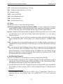
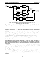
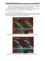
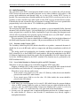
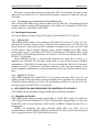
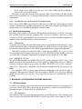
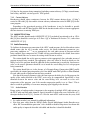
ATSC Recommended Practice:
Conversion of ATSC Signals for Distribution
to NTSC Viewers
Document A/79, 12 December 2008
Advanced Television Systems Committee, Inc.
1750 K Street, N.W., Suite 1200
Washington, D.C. 20006
Advanced Television Systems Committee
Document A/79
The Advanced Television Systems Committee, Inc., is an international, non-profit organization
developing voluntary standards for digital television. The ATSC member organizations represent
the broadcast, broadcast equipment, motion picture, consumer electronics, computer, cable,
satellite, and semiconductor industries.
Specifically, ATSC is working to coordinate television standards among different
communications media focusing on digital television, interactive systems, and broadband
multimedia communications. ATSC is also developing digital television implementation
strategies and presenting educational seminars on the ATSC standards.
ATSC was formed in 1982 by the member organizations of the Joint Committee on
InterSociety Coordination (JCIC): the Electronic Industries Association (EIA), the Institute of
Electrical and Electronic Engineers (IEEE), the National Association of Broadcasters (NAB), the
National Cable Telecommunications Association (NCTA), and the Society of Motion Picture and
Television Engineers (SMPTE). Currently, there are approximately 140 members representing the
broadcast, broadcast equipment, motion picture, consumer electronics, computer, cable, satellite,
and semiconductor industries.
ATSC Digital TV Standards include digital high definition television (HDTV), standard
definition television (SDTV), data broadcasting, multichannel surround-sound audio, and satellite
direct-to-home broadcasting. Contact information is given below.
Mailing address
Telephone
Web site
E-mail
Advanced Television Systems Commmittee, Inc.
1750 K Street, N.W., Suite 1200
Washington, D.C. 20006
202-872-9160 (voice)
202-872-9161 (fax)
http://www.atsc.org
[email protected]
Note: The user's attention is called to the possibility that compliance with this recommended
practice may require use of an invention covered by patent rights. By publication of this
document, no position is taken with respect to the validity of this claim or of any patent rights in
connection therewith. One or more patent holders may have filed a statement regarding the terms
on which such patent holder(s) may be willing to grant a license under these rights to individuals
or entities desiring to obtain such a license. The ATSC Patent Policy and Patent Statements are
available at http://www.atsc.org.
The revision history of this document is given below.
A/79 Revision History
A/79 approved
12 December 2008
2
Conversion of ATSC Signals for Distribution to NTSC Viewers, Table of Contents
12 December 2008
Table of Contents
1. SCOPE
7
1.1 Introduction and Background
7
2. REFERENCES
8
3. DEFINITIONS
10
3.1 Compliance Notation
3.2 Treatment of Syntactic Elements
3.3 Symbols, Abbreviations, and Mathematical Operators
3.4 Acronyms and Abbreviations
3.5 Terms
10
10
10
10
12
4. SYSTEM FUNCTIONALITY
12
5. ATSC RECEPTION AND PROCESSING FOR CONVERSION TO ANALOG (NTSC)
14
5.1 Reception and Decode
5.2 Video Processing
5.2.1 Conversion of Compressed Formats
5.2.1.1 Horizontal Dimension
5.2.1.2 Vertical Dimension
5.2.2 Aspect Ratio control
5.2.3 Color Space Conversions from HD to SD
5.3 Audio Processing
5.3.1 Main Program Audio
5.3.2 Secondary Audio Program (SAP)
5.3.3 Use of Audio Metadata for Determining Main and SAP Placement
5.3.4 Considerations for Continued Use of Existing Equipment
5.4 Data Signals Processing
5.4.1 CEA-608 Data
5.4.2 ANSI/SCTE 127 Data
6. ATSC RECEPTION AND PROCESSING FOR CONVERSION TO SD DIGITAL
14
14
15
15
15
15
16
17
17
17
17
18
18
18
18
18
6.1 Reception and Decode
18
6.2 Video Processing
19
6.2.1 Conversion of Compressed Formats
19
6.2.2 Aspect Ratio Control
19
6.2.3 Color Space Conversions from HD to SD
19
6.3 Audio Processing
19
6.3.1 Main Program Audio
19
6.3.2 Second Program Audio
19
6.3.3 Use of Audio Metadata for Determining Main and Second Audio Placement 19
6.3.4 Considerations for Continued Use of Existing Equipment
20
6.4 Data Signals Processing
20
6.4.1 CEA-608 Data
20
6.4.2 ANSI/SCTE 127 Data
20
7. BROADCAST STATION INFRASTRUCTURE GUIDELINES
7.1 AFD Infrastructure
20
20
3
Advanced Television Systems Committee
Document A/79
7.1.1 AFD Generation
7.1.2 Image Processing Considerations
7.1.3 VANC Data Considerations
7.1.4 AFD Insertion in the ATSC Encoder
7.2 ATSC Encoding Video Alignment
7.3 Closed Captioning and CEA-608 Data Infrastructure
7.3.1 CEA-608 Data
7.3.2 Content Advisory
7.4 ANSI/SCTE 127 Data
7.5 Audio Processing
7.5.1 Audio Metadata
7.6 PSIP Considerations
20
21
21
21
22
22
22
23
23
23
23
24
Annex A: Active Format Description
25
A1. INTRODUCTION
25
4
Conversion of ATSC Signals for Distribution to NTSC Viewers, Table of Contents
12 December 2008
Index of Tables and Figures
Table A.1 AFD Format Conversion Illustrations
26
Figure 4.1 Conceptual block diagram: ATSC bitstream conversion to analog NTSC
video, audio, and data.
Figure 4.2 Conceptual block diagram: ATSC bitstream conversion to digital SD SDI
video with audio and data.
Figure 4.3 Correct color matrix conversion; luminance portion of the color bar signal.
Figure 4.4 Incorrect color matrix conversion; luminance portion of the color bar signal.
5
13
14
16
16
ATSC Recommended Practice:
Conversion of ATSC Signals for Distribution
to NTSC Viewers
1. SCOPE
This Recommended Practice (RP) provides guidance to broadcasters and other creators of ATSC
high-definition (HD) or standard-definition (SD) content and to the operators of Multichannel
Video Programming Distributor (MVPD) systems (such as cable or direct to home satellite). It
recommends the equipment capabilities needed to provide the highest quality programming to
viewers who only receive NTSC services.
In case of any uncertainty about whether ATSC Transport Streams conform to the relevant
standards or to the recommendations in this document, then local coordination should occur to
resolve any ambiguous or omitted signaling.
This RP covers professional equipment and excludes any recommendations for design or
implementation of consumer equipment. Delivery to the home is not addressed by this
Recommendation.
1.1 Introduction and Background
In preparation for the 2009 digital transition, broadcasters, cable systems, and satellite providers
will need to arrange for distribution of broadcast channels to their standard definition viewers.
Many markets will not have direct access to NTSC or serial digital interface (SDI) SD versions of
broadcast services, but will be limited to direct reception of ATSC digital television (DTV)
signals. These DTV signals may contain HD or SD formats. This recommendation provides
guidance for the creation of the replacement NTSC signal. Two cases are explicitly covered and
one case is implicitly covered. The first case is direct delivery via NTSC on a RF channel. The
second case is for head-end facilities that have SDI interconnections from the broadcast station
signal receive rack to the multi-channel system transmit rack holding NTSC modulators or other
suitable transmission equipment, which may require different techniques than those used for
direct conversion to NTSC. These guidelines cover equipment capabilities needed to support both
scenarios. The implicit case is for multi-channel systems that do not have the ability to deliver an
analog signal (except at the output of the consumer’s STB), such as IPTV or DBS. In the implicit
case, the distribution system is treated as a “black box” with this recommendation only addressing
how to replicate the NTSC or baseband digital input to the IPTV or DBS head-end.
This document provides basic technical recommendations and guidelines for equipment
capabilities supporting distribution of HD originated broadcasts, SD 16:9, and all other ATSC
standard coding formats, with provision for either direct down-conversion to analog, or an
intermediary down-conversion to SDI, which then is converted to analog for rendering on
consumers’ NTSC sets.
When generating an NTSC or SDI signal, with associated audio and data, from the ATSC
transmitted format, the following capabilities should be considered:
1) Format conversion under control of AFD
Page 7
Advanced Television Systems Committee
Document A/79
2) Extraction of CEA-608 data
3) Preservation and distribution of content advisories
4) Preservation and distribution of ANSI/SCTE 127 data
5) Identification and proper AC-3 5.1 down-mix to Lt/Rt for main audio
6) Identification and proper AC-3 5.1 down-mix for second audio program (SAP)
7) Proper choice of AC-3 Dynamic Range Compression (DRC) profile
This recommendation does not include processing of ATSC signals for delivery to SCTE 54
or SCTE 128 compliant receivers. It is noted that the SCTE Standards for delivery of digital
transport streams using QAM signals, and the associated reception/decode for display via many
combinations of equipment are well documented by the cable industry.
2. REFERENCES
At the time of publication, the editions indicated below were valid. All documents are subject to
revision, and parties to agreement based on this RP are encouraged to investigate the possibility of
applying the most recent editions of the documents listed below.
[1] ATSC: “ATSC Digital Television Standard, Part 1 – Digital Television System,” Doc. A/53
Part 1:2007, Advanced Television Systems Committee, Washington, D.C., 3 January 2007.
[2] ATSC: “Recommended Practice – Transport Stream Verification,” Doc. A/78A, Advanced
Television Systems Committee, Washington, D.C., 9 May 2007.
[3] SMPTE: SMPTE 292 (2006), “1.5 Gb/s Signal/Data Serial Interface,” Society of Motion
Picture and Television Engineers, White Plains, N.Y.
[4] SMPTE: SMPTE 259M (2006), “SDTV Digital Signal/Data – Serial Digital Interface,”
Society of Motion Picture and Television Engineers, White Plains, N.Y.
[5] SMPTE: SMPTE 170M (2004), “Composite Analog Video Signal – NTSC for Studio
Applications,” Society of Motion Picture and Television Engineers, White Plains, N.Y.
[6] ATSC: “ATSC Digital Television Standard, Part 4 – MPEG-2 Video System Characteristics
with Amendment No. 1,” Doc. A/53 Part 4:2007, Advanced Television Systems Committee,
Washington, D.C., 24 December 2007 (Amendment No. 1 dated 24 December 2007).
[7] SMPTE: SMPTE 125M (1995), “Component Video Signal 4:2:2 – Bit-Parallel Digital
Interface,” Society of Motion Picture and Television Engineers, White Plains, N.Y.
[8] SMPTE: RP202 (2008), “Video Alignment for Compression Coding,” Society of Motion
Picture and Television Engineers, White Plains, N.Y.
[9] CEA: CEB16, “Active Format Description (AFD) and Bar Data Recommended Practice,”
Consumer Electronics Association, Arlington, VA, 31 July 2006.
[10] ITU: ITU-R BT.709-5 (2002), “Parameter Values for the HDTV Standards for Production
and International Programme Exchange”.
[11] ITU: ITU-R BT.601-5 (1995), “Studio Encoding Parameters of Digital Television for
Standard 4:3 and Wide-Screen 16:9 Aspect Ratios”.
8
Conversion of ATSC Signals for Distribution to NTSC Viewers
12 December 2008
[12] FCC: OET Bulletin No. 60, Revision A (1986), “Multichannel Television Sound
Transmission and Audio Processing Requirements for the BTSC System.”
[13] ATSC: “Digital Audio Compression Standard (AC-3, E-AC-3),” Doc. A/52B, Advanced
Television Systems Committee, Washington, D.C., 14 June 2005.
[14] CEA: CEA-608-D, “Line 21 Data Services,” Consumer Electronics Association, Arlington,
VA, May 2007.
[15] SCTE: ANSI/SCTE 127-2007, “Carriage of Vertical Blanking Interval (VBI) Data in North
American Digital Television Bitstreams,” Society of Cable Telecommunications Engineers,
Exton, PA.
[16] CEA: CEA-708-D, “Digital Television (DTV) Closed Captioning,” Consumer Electronics
Association, Arlington, VA, August 2008.
[17] ATSC: “Carriage of Legacy TV Data Services,” Doc. A/99, Advanced Television Systems
Committee, Washington, D.C., 23 July 2008.
[18] SMPTE: SMPTE 334-1-2007, “Vertical Ancillary Data Mapping of Caption Data and Other
Related Data,” Society of Motion Picture and Television Engineers, White Plains, N.Y.
[19] SMPTE: SMPTE 2031 (2007), “Carriage of DVB/SCTE VBI Data in VANC,” Society of
Motion Picture and Television Engineers, White Plains, N.Y.
[20] SMPTE: SMPTE 2016-1 (2007), “Format for Active Format Description and Bar Data,”
Society of Motion Picture and Television Engineers, White Plains, N.Y.
[21] SMPTE: SMPTE 2016-3 (2007), “Vertical Ancillary Data Mapping of Active Format
Description and Bar Data,” Society of Motion Picture and Television Engineers, White
Plains, N.Y.
[22] SMPTE: SMPTE 333-2008, “DTV Closed-Caption Server to Encoder Interface,” Society of
Motion Picture and Television Engineers, White Plains, N.Y.
[23] SMPTE: EG43-2004, “System Implementation of CEA-708-B and CEA-608-B Closed
Captioning,” Society of Motion Picture and Television Engineers, White Plains, N.Y.
[24] SMPTE: SMPTE 334-2 (2007), “Caption Distribution Packet (CDP) Definition,” Society of
Motion Picture and Television Engineers, White Plains, N.Y.
[25] ATSC: “Program and System Information Protocol for Terrestrial Broadcast and Cable
(Revision C) With Amendment No. 1,” Doc. A/65C, Advanced Television Systems
Committee, Washington, D.C., 9 May 2006.
[26] ATSC: “ATSC Digital Television Standard, Part 3 – Service Multiplex and Transport
Subsystem Characteristics,” Doc. A/53 Part 3:2007, Advanced Television Systems
Committee, Washington, D.C., 3 January 2007.
[27] CEA: CEA-2020:2006, “Other VBI Waveforms,” Consumer Electronics Association,
Arlington, VA, August 2006.
[28] DVB/ETSI: ETSI TS 101 154 V1.8.1, Digital Video Broadcasting (DVB): “Implementation
Guidelines for the use of MPEG-2 Systems, Video and Audio in Satellite, Cable and
Terrestrial Broadcasting Applications,” Annex B, June 2007.
9
Advanced Television Systems Committee
Document A/79
[29] SCTE: ANSI/SCTE 54-2004, “Digital Video Service Multiplex and Transport System
Standard for Cable Television,” Society of Cable Telecommunications Engineers, Exton, PA.
[30] SCTE: ANSI/SCTE 128 2007, “AVC Video Systems and Transport Constraints for Cable
Television,” Society of Cable Telecommunications Engineers, Exton, PA.
3. DEFINITIONS
3.1 Compliance Notation
This RP contains no normative references or mandatory requirements.
3.2 Treatment of Syntactic Elements
This document contains symbolic references to syntactic elements used in the audio, video, and
transport coding subsystems. These references are typographically distinguished by the use of a
different font (e.g., restricted), may contain the underscore character (e.g., sequence_end_code) and
may consist of character strings that are not English words (e.g., dynrng).
3.3 Symbols, Abbreviations, and Mathematical Operators
The symbols, abbreviations, and mathematical operators used herein are as found in Section 3.4
of ATSC A/53 Part 1 [1] and as herein specified. Numbers preceded by 0x are to be interpreted as
hexadecimal values and numbers within single quotes (e.g., ‘10010100’) are to be interpreted as a
string of binary digits.
3.4 Acronyms and Abbreviations
The following acronyms and abbreviations are used within this specification.
AC-3 – ATSC Digital Audio Compression Standard (see A/52 [13])
AFD – Active Format Description
AMOL – Automated Measurement of Lineups
ANSI – American National Standards Institute
ASI – Asynchronous Serial Interface
ATSC – Advanced Television Systems Committee
BTSC – Broadcast Television Systems Committee
CEA – Consumer Electronics Association
CDP – Caption Distribution Packet
CM – Component Missing (see A/78 [2])
compr
– DRC variable
dBFS – deciBels Full Scale
DBS – Direct Broadcast Satellite
DRC – Dynamic Range Compression
DTV – Digital Television
10
Conversion of ATSC Signals for Distribution to NTSC Viewers
12 December 2008
DVB – Digital Video Broadcasting
dynrng
– DRC variable
EIT – Event Information Table
ETSI – European Telecommunications Standards Institute
FCC – Federal Communications Commission
FM – Frequency Modulation
IPTV – Internet Protocol (IP) Television
IRD – Integrated Receiver/Decoder (sometimes termed Receiver/Descrambler, but not in these
systems. ATSC content is always in the “clear”)
ITU – International Telecommunication Union
HANC – Horizontal ANCillary
HD – High-Definition
HDTV – High-Definition Television
HD-SDI – High-Definition Serial Digital Interface (compliant with SMPTE 292 [3])
MPEG – Moving Picture Experts Group
MVPD – Multichannel Video Programming Distributor
NTSC – National Television System Committee
PCM – Pulse Code Modulation
PID – Packet IDentifier
PIRD – Professional Integrated Receiver/Decoder (see IRD above)
POA – Program Off Air (see A/78 [2])
PSIP – Program and System Information Protocol
QAM – Quadrature Amplitude Modulation
QOS – Quality of Service (see A/78 [2])
RF – Radio Frequency
RP – Recommended Practice
SAP – Secondary Audio Program
SCTE – Society of Cable Telecommunications Engineers
SD – Standard Definition
SDI – Serial Digital Interface (compliant with SMPTE 259M [4])
SDTV – Standard Definition Television
SMPTE – Society of Motion Picture and Television Engineers
STB – Set-Top Box
11
Advanced Television Systems Committee
Document A/79
TNC – Technically Non-Conformant (see A/78 [2])
TOA – Transport-stream Off-Air (see A/78 [2])
TS – Transport Stream
VANC – Vertical ANCillary
VBI – Vertical Blanking Interval
VSB – Vestigial Sideband
XDS – eXtended Data Services
3.5 Terms
The following terms are used within this specification.
ATSC Professional Integrated Receiver/Decoder (PIRD) – A device employed in a broadcast
station, MVPD headend or similar professional location, which has the capability to produce
NTSC or SDI video, with associated audio and data, from all ATSC standard formats.
Bar data – Additional information which accompanies AFD data providing exact sizes of either
top and bottom bars or side bars for image aspect ratios other than 4:3 or 16:9 such as
widescreen movies.
Line – A specification of a given television scanning line number, defined in different image
format standards. For NTSC, the line numbers are as defined by Figure 7 of SMPTE 170M
[5]1.
VANC – An acronym for Vertical ANCillary (data space). In a broadcast facility, in uncompressed
SDI/HD-SDI, the Vertical ANCillary (VANC) data space is used for VBI and other non-video
signals.
VBI – An acronym for Vertical Blanking Interval, which is composed of the first 20 horizontal
lines in each NTSC field (see definition of Line, above). These lines are not intended to be
directly displayed by a receiver. In digital systems, the VBI does not exist, although the line
numbers are allocated as if it does. Frequently, lines 21 and 22 are considered a part of VBI,
but such classification is technically incorrect.
4. SYSTEM FUNCTIONALITY
There are several different system architectures that may be deployed by MVPDs.
1) Systems which pass through the ATSC Transport Stream with minor modifications (such as
changing the Terrestrial Virtual Channel Table in the PSIP for a Cable Virtual Channel Table).
This document will not discuss this system architecture further.
2) Systems which convert the ATSC Transport Stream into an analog NTSC signal and modulate
that for delivery to their customers. Such a system is outlined in Figure 4.1 and discussed in
Section 5.
1. Note that SMPTE 170M [5] does not use “Field x, Line y” nomenclature, rather lines are
numbered from the start of Fields 1 and 3. See ANSI/SCTE 127 § 7.1.4 for a conversion
formula.
12
Conversion of ATSC Signals for Distribution to NTSC Viewers
ATSC
transport
stream
MPEG-2 TS
DEMUX
Video PES
Video PES
708 caption
extractor
12 December 2008
608 compatibility
bytes extraction
608 Data
Video decoder
525 line
video
Video PES
AFD
extractor
SCTE 127
data
extractor
Video
format
conversion
AFD
formatting
information
Data
insertion
525 line
video
with
data
NTSC
composite
video
NTSC
Encoder
AMOL and other data
Main audio
program
select
Main audio
program
decoder
Audio
downmix to
stereo/LtRt
Second audio
program
select
Second audio
program
decoder
Audio
downmix to
mono
Stereo/LtRt
program
audio
To BTSC
encoder
and RF
modulator
Mono
SAP audio
NOTE: Care must be taken to ensure the proper synchronization of video, audio, and
associated data at the output of this system
Figure 4.1 Conceptual block diagram: ATSC bitstream conversion to analog NTSC video, audio,
and data.
3) Systems which convert the ATSC Transport Stream into a digital 4:3 SD signal and then send
that digitized signal to the MVPD transmit rack. Such a system is outlined in Figure 4.2 and
discussed in Section 6. Note that in this case the transmit rack may hold NTSC modulators or
suitable transmission equipment for digital systems such as IPTV or DBS. The possible
further compression stage during distribution should be kept in mind during the discussion in
Section 6.
Some MVPDs currently convert the legacy NTSC input signal to digital form (or accept a predigitized signal) and use a digital infrastructure to deliver the digital signal to NTSC generators2
at points remote from the input. The other directly provided digital signals that may use this same
infrastructure are private by nature and are out of scope of this RP.
This RP does not address delivery of digital signals to residences and is silent on the
requirements that exist for MVPD owned and/or consumer owned devices in residences which
include providing NTSC signals with certain characteristics.
While legal and regulatory advice for such devices is out of scope of this document, the
reader’s attention is drawn to the FCC Rules dealing with digital conversion of ATSC signals by
consumer devices with NTSC outputs if the delivery system does not provide NTSC signals
directly to consumer devices.
Figures 4.1 and 4.2 are conceptual block diagrams showing the steps that must be taken to
properly recover the video, audio, and data signals but not necessarily in the precise order required
2. These generators may be found in home STBs or other locations. Such NTSC generation
processes are out of scope of this RP.
13
Advanced Television Systems Committee
ATSC
transport
stream
MPEG-2 TS
DEMUX
Video PES
Video PES
Document A/79
608
compatibility
bytes
extraction
708 caption
extractor
Video decoder
608 Data
Digital
video
Digital 525 line
video with
VANC or VBI
data
525 line
video
Video PES
AFD
extractor
SCTE 127
data
extractor
Video
format
conversion
AFD
formatting
information
VANC/VBI data
formatter
Main audio
program
select
SMPTE 337
HANC data
formatter
Second audio
program
select
SMPTE 337
HANC data
formatter
VANC/
VBI
insertion
HANC
insertion
SD SDI
To MVPD
transport
rack
AMOL and
other data
Main
program
audio
Second
audio
NOTE: Care must be taken to ensure the proper synchronization of video, audio, and
associated data at the output of this system
Figure 4.2 Conceptual block diagram: ATSC bitstream conversion to digital SD SDI video with
audio and data.
to build an implementation. It is out of scope for this document to supply implementation
specifics.
MVPD system operators should understand these block diagrams as outlining functionality
which should be included in equipment they deploy; again, with the understanding that different
devices may process steps differently.
5. ATSC RECEPTION AND PROCESSING FOR CONVERSION TO ANALOG (NTSC)
ATSC PIRDs with analog NTSC outputs should have the following capabilities.
5.1 Reception and Decode
ATSC PIRDs should support reception and decoding of 8-VSB ATSC signals that conform to
ATSC Digital Television Standard A/53 [1]. The conceptual block diagram (Figure 4.1) does not
include RF or other electrical interfaces, rather assumes an MPEG-2 Transport Stream (TS) as a
starting point.
MPEG-2 TS monitoring and alarm generation should follow the ATSC A/78 [2]
recommendations. Default alarming should be restricted to TOA, POA, and CM, with selection of
QOS at operator discretion. TNC errors should be ignored.
5.2 Video Processing
When an NTSC analog video signal with associated audio and data is not directly available from a
broadcast station, the MVPD may derive this signal from the available ATSC signal. To ensure
proper formatting and delivery of the converted signal, ATSC PIRDs should have the following
capabilities.
14
Conversion of ATSC Signals for Distribution to NTSC Viewers
5.2.1
12 December 2008
Conversion of Compressed Formats
ATSC PIRDs should support format conversion of any A/53 Part 4 [6] Table 6.2 video format, as
well as the 720x480 video format, to NTSC analog format in accordance with SMPTE 170M [5].
5.2.1.1
Horizontal Dimension
1080-line and 720-line HD video formats should be downconverted to fill an active line with 720
pixels as defined in SMPTE 125M [7].
480-line SD video may be coded as lines of 720, 704, or 640 pixels. If coded as 720 pixels, the
reconstructed video will map directly into an active line as defined in SMPTE 125M [7].
If the coded video lines are 704 pixels long, the reconstructed video should be centered on the
line as defined in SMPTE 125M [7], with the first eight and last eight pixels of the full 720-pixel
active line set at black.
Video coded as 640x480 should be scaled horizontally to fill the full active line as defined in
SMPTE 125M [7].
SMPTE 125M [7] defines the relationship between the 525-line digital pixel samples and the
equivalent analog video signal required for the output of the conversion process.
5.2.1.2
Vertical Dimension
In analog NTSC services, the first line of the picture is line 23; the preceding lines (even those
defined as “active video” in the FCC Rules) typically contain data services (including captions) or
test signals. It is therefore recommended that PIRDs with downconversion capabilities should
convert all incoming HD or SD signals to 480 lines, which should include any bars inserted as
part of the aspect ratio conversion (see Section 5.2.2). The first line of converted video (including
such bars, if present) should be placed on line 23 of the analog video output. This arrangement
allows for new line 21 data to be added to the NTSC output signal (see Section 5.4.1). It should be
noted that for letterbox output video, the first line of the active image will typically start at line 53.
Although ATSC A/53 Part 4 [6] Table 6.2 SD formats all specify a vertical size value of 480
lines, SMPTE 170M [5] and SMPTE 125M [7] (both of which predate the widespread use of
video compression) stipulate 486 lines for the image size. Some existing baseband downconverter
units may produce image sizes with more than 480 lines, typically in the range 484 to 487 lines.
This variation from the recommendation for 480 lines should be recognized if such format
converters are used in a MVPD facility.
Implementers should consult SMPTE RP202 [8] for additional guidance on format
conversions.
5.2.2
Aspect Ratio control
In conversion to a 4:3 SD raster, ATSC PIRDs should support aspect ratio control with the
following configurable options for 16:9 source conversion to the 4:3 aspect ratio:
• “Center-Cut” – forced aspect ratio conversion to center-cut, ignoring AFD
• “Letterbox” – forced aspect ratio conversion to letterbox, ignoring AFD
• “Auto” – automatic selection of center-cut or letterbox as activated by the ATSC AFD data
decoded from input. (See Annex A for details).
When in Auto, ATSC PIRDs should support control of picture aspect ratio through AFD with
the following additional capabilities
• Switch between aspect ratio modes should be frame accurate following AFD data.
15
Advanced Television Systems Committee
Document A/79
•
When valid AFD data is no longer present, ATSC PIRDs should be able to automatically
switch to a user programmable setting (center-cut or letterbox). This is intentionally
different from the consumer equipment advice given in CEA-CEB16 [9].
If the incoming signal has a 4:3 coded frame, under all circumstances the full frame should be
used and the output signal should be 4:3. Any AFD present should be ignored.
5.2.3
Color Space Conversions from HD to SD
When the HDTV signal is downconverted the ITU-R BT.709 [10] color space should be converted
to NTSC (SMPTE 170M [5] / SMPTE 125M [7] / BT.601 [11]) color space. Figure 4.3 shows a
correct downconversion, while Figure 4.4 shows a color matrix error.
Figure 4.3 Correct color matrix conversion; luminance portion of the color bar signal.
Figure 4.4 Incorrect color matrix conversion; luminance portion of the color bar signal.
16
Conversion of ATSC Signals for Distribution to NTSC Viewers
12 December 2008
5.3 Audio Processing
The conversion of the ATSC sound program should be done in a manner that will present the
NTSC listener with main and secondary program services whose loudness (with respect to 100
percent aural modulation) and dynamic range are as close to the existing NTSC services as
possible. The conversion process should consider the fact that NTSC receivers may not be able to
reproduce as wide a dynamic range audio signal as some ATSC receivers or home theater systems.
It should also take into account that the gain structure of existing NTSC receivers is optimized for
program dialog levels in the order of 17 to 20 dB below peak FM modulation.
5.3.1
Main Program Audio
The main program audio decoder should be set to produce a stereo-compatible Dolby Surround
downmix (also called Pro Logic®, Left-total/Right-total, or Lt/Rt downmix) of the multichannel
source program that is suitable for Dolby Surround Pro Logic® decoding (this downmix mode
will not affect an incoming stereo program signal). It should also be set to RF Mode3, and have
compression and dialog normalization enabled at all times.
The gain structure of the converter should allow a 0 dBFS signal level in the digital domain of
the Main Audio Program decoder to produce 100 percent modulation of the NTSC aural carrier.
5.3.2
Secondary Audio Program (SAP)
The Secondary Audio Program (SAP) decoder should be set to produce a monaural4 downmix. It
should also be set to the RF mode, and have compression and dialog normalization enabled at all
times.
The analog signal levels produced by the Secondary Audio Program decoder (or associated
DACs) should be set so that 0 dBFS SAP signal produces 100 percent modulation in the BTSC
[12] domain. Implementers should also ensure that the bandwidth of the SAP channel does not
exceed the 10 kHz mandated by the BTSC standard. (This function may be performed by the
BTSC modulator itself.)
5.3.3
Use of Audio Metadata for Determining Main and SAP Placement
When there is only one audio stream, it should be mapped to NTSC main audio.
Mapping of multiple ATSC audio streams to the NTSC main and SAP audio channels should
be based on the priority field of the AC-3 descriptor defined in A/52 [13], Section A.3.4.
When there is more than one audio stream:
• If one stream’s priority field is set to the value ‘01’ (Primary Audio) that stream should be
placed on the main BTSC audio channel.
• If one stream’s priority field is set to the value ‘10’ (Other Audio) that stream should be
placed on the SAP channel.
3. In RF Mode, the overall program level is raised 11 dB (which brings the program loudness
closer to NTSC practice) while the peaks are limited to prevent signal overload in the D/A
converter. Also see ATSC Digital Audio Compression Standard (AC-3, E-AC-3) A/52 [13]
Sections 7.7.2 and 7.7.2.1 for details of the compr gain word used in the RF Mode.
4. In some cases, the monaural sum is implemented downstream from the 2-channel output of
the audio decoder IC. However, some decoder IC manufacturers may directly support a
monophonic downmix.
17
Advanced Television Systems Committee
Document A/79
When three or more audio streams are present in the ATSC Virtual Channel, all audio streams
that have the priority field set to ‘11’ (Not specified) should be assumed to be neither the main nor
SAP audio.
5.3.4
Considerations for Continued Use of Existing Equipment
Some existing ATSC PIRDs select and route audio services by PID value. The broadcaster should
attempt to maintain consistent PID assignments for the audio service intended for NTSC Main
and the audio service intended for NTSC SAP.
5.4 Data Signals Processing
This section addresses the processing of CEA-608 [14] and ANSI/SCTE 127 [15] data.
5.4.1
CEA-608 Data
ATSC PIRDs should conform to the guidelines of CEA-708 [16], Sections 9.23, 9.24, 9.25, 10.1,
and Annex B regarding the processing of CEA-608 [14] datastream bytes. All CEA-608 [14]
datastream bytes are expected to be present, including all 4 caption services, all 4 text services and
all XDS packets. Special attention should be paid to decoder handling of the XDS content
advisory packet (type=5) according to CEA-708 [16]. When present, CEA-608 [14] data carried
per A/53 Part 4 [6] should take precedence over any line 21 (or line 284) data present in ANSI/
SCTE 127 [15] payloads.
Where CEA-608 [14] data is recovered and reinserted into analog line 21 format, it is
important that CEA-608 [14] null pairs (0x80, 0x80) are not inserted between redundant
transmissions of CEA-608 [14] control pairs. It has been found that CEA-608 [14] decoders
compliant with FCC specifications will display anomalies if this null code insertion occurs
between redundant transmissions of certain command pairs and all special and extended character
pairs.
5.4.2
ANSI/SCTE 127 Data
ATSC PIRDs should decode ANSI/SCTE 127 [15] payloads carried per ATSC A/99 [17] and
should re-encode all the payload data as analog waveforms on the appropriate line. When present,
CEA-608 [14] data carried per A/53 Part 4 [6] should take precedence over any line 21 (or line
284) data present in ANSI/SCTE 127 [14] payloads.
6. ATSC RECEPTION AND PROCESSING FOR CONVERSION TO SD DIGITAL
ATSC PIRDs with baseband digital outputs should have the following capabilities.
6.1 Reception and Decode
ATSC PIRDs should support reception and decoding of 8-VSB ATSC signals that conform to
ATSC Digital Television Standard A/53 [1]. The conceptual block diagram (Figure 4.2) does not
include RF or other electrical interfaces, rather assumes an MPEG-2 Transport Stream (TS) as a
starting point.
MPEG-2 TS monitoring and alarm generation should follow the ATSC A/78 [2]
recommendations. Default alarming should be restricted to TOA, POA, and CM, with selection of
QOS at operator discretion. TNC errors should be ignored.
18
Conversion of ATSC Signals for Distribution to NTSC Viewers
12 December 2008
6.2 Video Processing
When a 4:3 SD digital SDI video signal with associated audio and data is not directly available
from a broadcast station, the MVPD may derive this signal from the available ATSC signal. To
ensure proper formatting and delivery of the converted signals, ATSC PIRDs should have the
following capabilities.
6.2.1
Conversion of Compressed Formats
The considerations detailed in Section 5.2.1 apply except that the output video format should be
SDI (SMPTE 259M [4] compliant).
6.2.2
Aspect Ratio Control
The considerations detailed in Section 5.2.2 apply except that the output video format is SDI.
6.2.3
Color Space Conversions from HD to SD
The considerations detailed in Section 5.2.3 apply except that the output video format is SDI.
6.3 Audio Processing
The ATSC PIRD should produce PCM or a passed-through AC-3 stream. Depending on the
system architecture, the digital audio signals from the ATSC PIRD may be either embedded in the
video SDI signal (as shown in Figure 4.2) or provided as separate non-embedded outputs.
In all cases, care must be taken to preserve audio/video synchronization. Audio may be
embedded with its associated video or routed directly.
6.3.1
Main Program Audio
If the downstream equipment being fed directly by the PIRD supports PCM, then the ATSC
Professional PIRD should output left and right channel PCM for the SDI transport. If the
downstream equipment supports AC-3 inputs, then that should be output. The advantage of using
AC-3 is the associated AC-3 metadata can then reach other equipment downstream. In any case
the audio processing recommendations of Section 5.3 should be followed.
6.3.2
Second Program Audio
If the downstream equipment being fed directly by the PIRD supports PCM, then the ATSC
Professional PIRD should output monaural PCM for the SDI transport. If the downstream
equipment supports AC-3 inputs, then that is also an option. The advantage of using AC-3 is the
associated AC-3 metadata can then reach other equipment downstream. In any case the audio
processing recommendations of Section 5.3 should be followed.
6.3.3
Use of Audio Metadata for Determining Main and Second Audio Placement
When there is only one audio stream, it should be mapped to main audio.
Mapping of multiple ATSC audio streams to the main and second audio channels should be
based on the priority field of the AC-3 descriptor defined in A/52 [13], Section A.3.4.
When there is more than one audio stream:
• If one stream’s priority field is set to the value ‘01’ (Primary Audio) that stream should be
placed on the main audio channel.
19
Advanced Television Systems Committee
Document A/79
•
If one stream’s priority field is set to the value ‘10’ (Other Audio) that stream should be
placed on the second audio channel.
When three or more audio streams are present in the ATSC Virtual Channel, all audio streams
that have the priority field set to ‘11’ (Not specified) should be assumed to be neither the main nor
second audio.
6.3.4
Considerations for Continued Use of Existing Equipment
Some existing ATSC PIRDs select and route audio services by PID value. The broadcaster should
attempt to maintain consistent PID assignments for the audio service intended for SD digital main
and the audio service intended for SD digital secondary audio.
6.4 Data Signals Processing
Processing of data signals is of necessity different from their handling in an NTSC conversion.
The metadata associated with the incoming ATSC TS that is needed to control the eventual
creation of an NTSC signal (including data) as described in see Section 5 should be mapped into a
suitable carriage method for delivery to the transmit rack.
6.4.1
CEA-608 Data
To provide a data service consistent with current practices for distribution of broadcasters’ analog
signals, CEA-608 [14] data, as detailed in Section 5.4.1, should be delivered to the digital system
for eventual insertion into line 21 of the NTSC output signal in other equipment downstream.
CEA-608 [14] data may be inserted in SDI as VANC data per SMPTE 334-1 [18] or as VBI
data consisting of digital samples of the analog waveform. CEA-608 [14] data should be conveyed
in a format that is compatible with downstream equipment being fed directly by the PIRD.
6.4.2
ANSI/SCTE 127 Data
The ATSC PIRD should decode ANSI/SCTE 127 [15] payloads carried per ATSC A/99 [17] and
should either insert all the payload data as VANC packets per SMPTE 2031 [19] or as VBI data
consisting of digital samples of the analog waveform. ANSI/SCTE 127 [15] data should be
conveyed in a format that is compatible with downstream equipment being fed directly by the
PIRD.
Care should be taken to ensure proper timing in relationship to the associated video is
maintained. When present, CEA-608 [14] data carried per SMPTE 334-1 [18] or as VBI data
should take precedence over any line 21 (or line 284) data present in ANSI/SCTE 127 [15]
payloads.
7. BROADCAST STATION INFRASTRUCTURE GUIDELINES
7.1 AFD Infrastructure
In order for the automatic aspect ratio control function described in Section 5 to work correctly, it
is necessary for the ATSC video signal from the broadcaster to include associated AFD data as
described in Annex A. Points to note are described below.
7.1.1
AFD Generation
How and where AFD is generated will depend on the operational practices of the broadcaster but
in most cases the data defined in SMPTE 2016-1 [20] is expected to be inserted into the VANC in
20
Conversion of ATSC Signals for Distribution to NTSC Viewers
12 December 2008
baseband SDI or HD-SDI signals as described in SMPTE 2016-3 [21]. AFD insertion may occur
in various places, such as during production or postproduction of programs and advertisements, at
network facilities, at the syndicator, and at local broadcast stations. Specifics are out of scope of
this RP.
In all cases, the AFD should correctly describe the image characteristics of the associated
video signal. Full AFD information always includes the aspect ratio of the coded frame, as well as
the four-bit AFD code.
During insertion of commercial advertisements, care should be taken to ensure the correct
AFD information describing the advertisement’s image characteristics is signaled.
AFD codes may also be set as part of the ATSC encoding process under automation control,
see Section 7.1.4.
SMPTE 2016-1 [20] and ATSC A/53 Part 4 [6] also define bar data that may be associated
with AFD. The use of bar data is not covered in this RP.
7.1.2
Image Processing Considerations
Various video processes that signals pass through during the broadcast production and distribution
chain may change the aspect ratio of the active image area and/or coded frame. These include: up
and down format converters, aspect ratio converters, video switchers, and digital video effects
units. Whenever such video processing and conversion occurs, the equipment should process the
associated incoming AFD such that the AFD data on the output correctly describe the associated
output video signal, as described in SMPTE 2016-1 [20], Section 7.
It should be noted that while AFD signaling helps to eliminate the “postage stamp” affect that
can occur when receivers show bars all around a small active image, broadcasters still need to
ensure that signals coded for transmission do not lead to this effect. In particular, AFD cannot
signal the presence of “letterbox” and “pillarbox” bars simultaneously, so such picture formats
should never be broadcast.
7.1.3
VANC Data Considerations
Many devices in the studio processing chain (e.g., production switchers, digital effects units,
recorders, and video servers) may pass data on only a small subset of lines in the VANC space and
some devices may not pass VANC packets at all. Care should therefore be taken in selecting the
location of AFD data packets to be carried in VANC and in designing video systems to ensure that
the integrity of the VANC data path is maintained. Guidance on this is provided in Annex B of
SMPTE 2016-3 [21].
Contribution and network distribution systems often carry video in compressed form where
VANC data is not included. In this case, other arrangements should be made to enable the data to
be distributed to the destination along with the video.
7.1.4
AFD Insertion in the ATSC Encoder
Irrespective of where it is originally generated, for over-the-air transmission the AFD data is
inserted into video user data by the ATSC station encoder.
Many current generation encoders are capable of extracting the AFD data placed in VANC
and inserting it into the MPEG-2 video user data. Some encoders are also capable of setting AFD
codes based on user presets or external commands.
21
Advanced Television Systems Committee
Document A/79
Station output bitstreams using AFD should at all times contain valid AFD data consistent
with the associated video. The intermittent presence of AFD is highly undesirable as it may result
in unknown operation of equipment downstream.
7.2 ATSC Encoding Video Alignment
It is recommended that the spatial alignment of pixels and lines set out in SMPTE RP202 [8]
should be used for the ATSC encoding of video signals for broadcast. This will help ensure that
signal decoding and conversion occurring downstream will result in output signals with optimum
video images. This is especially important for SD signals where the vertical placement of the
coded 480 lines can vary if not correctly specified. It is also noted that the inclusion of line 21 and
line 22 in broadcast DTV programming may result in very visible and undesirable visual artifacts
at the top of the picture on many DTV receiver displays and this should be avoided.
7.3 Closed Captioning and CEA-608 Data Infrastructure
ATSC transmissions must conform to the requirements of A/53 Part 4 [6] regarding the carriage
of CEA-708 [16] closed caption data. Such caption data may be supplied to the ATSC encoder via
mechanisms defined in SMPTE 334-1 [18] or SMPTE 333 [22] (and possibly others).
Guidance on the implementation of systems for DTV closed captioning is provided in SMPTE
EG43 [23]. Typically such systems use caption distribution packets (CDPs), now defined in
SMPTE 334-2 [24], which include CEA-708 [16] caption data, CEA-608 [14] data, and caption
service information.
As occurred with NTSC program distribution, insertion of closed captioning data may occur
at the network release facility and some captioning may occur at the local broadcast station.
Current generation CEA 708 [16] caption equipment allows for CDPs distributed with a video
signal from a network to be modified if necessary downstream at the local station so that captions
may be added or modified for the program being transmitted.
7.3.1
CEA-608 Data
In accordance with the requirements of A/53 Part 4 [6] as well as the guidelines of CEA-708 [16],
the closed captioning data carried in the ATSC bitstream from the broadcaster should include
CEA-608 [14] data as well as CEA-708 [16] captioning data.
It is important to note that the CEA-608 [14] data should include all the data that would
normally have carried in the broadcaster’s previous NTSC service, including all 4 caption
services, all 4 text services and all XDS bytes.
Where the CEA-608 [14] data is generated and inserted into the CDPs depends on the
operational practices of the broadcaster. If an NTSC signal chain including CEA-608 [14] line 21
data is maintained within the broadcast facility, then the CEA-608 [14] data may be simply
bridged to the CEA-708 [16] caption generator device that inserts the CDPs into the SDI or HDSDI video signal. Where the line 21 infrastructure is no longer present, then alternative paths
should be established to provide this data to the CEA-708 [16] caption generator.
As occurred with NTSC program distribution, some CEA-608 [14] data may originate at the
network release facility and some or all at the local broadcast station. Current generation CEA708 [16] caption equipment allows for CDPs distributed with a video signal from a network to be
modified if necessary downstream at the local station so they include valid and current CEA-608
22
Conversion of ATSC Signals for Distribution to NTSC Viewers
12 December 2008
[14] data for the program being transmitted, including content advisory (V-Chip), network name,
time-of-day, and other “air time specific” XDS packets.
7.3.2
Content Advisory
Broadcasters should ensure consistency between the XDS content advisory bytes (“V-chip”)
carried in CEA-608 [14] data and the content advisory information carried in PSIP [25] for the
same program.
Depending on the operational practices of the broadcaster, it may be desirable to provide
equipment that reads EIT data from the PSIP for the broadcast and verifies or inserts appropriate
data into incorrect or missing XDS bytes.
7.4 ANSI/SCTE 127 Data
The ATSC encoder should encode ANSI/SCTE 127 [15] payloads if provisioned to do so. CEA608 [14] data should be carried per A/53 Part 4 [6] as mentioned in Section 7.2.1, rather than
ANSI/SCTE 127 [15].
7.5 Audio Processing
To facilitate the downstream conversion of the ATSC sound program, the local broadcast station
should ensure that the AC-3 encoder audio service, bit stream information parameters, preprocessing conditions etc.5 6, are set appropriately for each audio stream of program material
being encoded. If pre-compressed AC-3 audio is being passed-through at the station, then station
personnel should take care to ensure the settings in the stream are correct.
The station should also set the dialnorm parameter value appropriately for each audio stream of
program material being encoded. The appropriate value may either be fixed, in which case the
dialog level of the program should be adjusted (before transmission) to match the fixed dialnorm
value, or the dialnorm parameter should be set to match the actual dialog level of each program
being transmitted.
The station should also set, in the absence of a Dynamic Range Compression (DRC) profile
specified by the original program producer, the Line and RF mode DRC profiles to Film Standard,
for each audio stream of program material being encoded.
Note that if the dialnorm parameter value does not represent the dialog level of the program, the
quality of the audio delivered to the NTSC service may be compromised. Specifically, a large
mismatch between the dialnorm value and the actual dialog level can result in severe overcompression of the program, even if the encoder compression profile is set to “None”. This is
done to avoid the possibility of even more annoying signal clipping in the decoder.
7.5.1
Audio Metadata
Proper setting of audio metadata is important to the mapping of multiple ATSC audio streams to
the NTSC main and SAP audio channels. Special attention is called to the priority field of the AC-3
descriptor defined in A/52 [13], Section A.3.4. For the main ATSC audio stream, the priority field
5. See audio encoder’s user manual for additional information.
6. Note that some older (than the DP569) Dolby Digital Multichannel Audio Encoders may
allow “RF Overmodulation protection” to be enabled or disabled. Experience has shown that
audio quality is improved when this is disabled and therefore it should be disabled.
23
Advanced Television Systems Committee
Document A/79
should be set to the value ‘01’ (Primary Audio). For an ATSC audio stream intended to be mapped
to the NTSC SAP audio, the priority field should be set to ‘10’ (Other Audio).
When three or more audio streams are present in the ATSC Virtual Channel, for all audio
streams that are neither the main nor SAP audio, the priority field should be set to ‘11’ (Not
specified) for each.
Although not needed for audio mapping, encoders should also ensure the language field is
properly set according to A/53 Part 3 [26], and, when more than one audio service has the same
language, the component_name_descriptor is required to be added according to A/65 [25].
7.6 PSIP Considerations
Station personnel need to understand that per ATSC A/65 [25] and the FCC Rules, they will
continue to use their pre-transition major channel number, which in all cases was an NTSC
broadcast channel assignment. This applies to those few stations which surrendered their analog
channels pre-transition. Failure to use their analog channel number as their major channel number
will result in confusing both their viewing audience (who are accustomed to thinking of channel
‘N’) and the relevant MVPDs (who are also accustomed to thinking of the station as channel ‘N’).
24
Annex A:
Active Format Description
1. INTRODUCTION
Active Format Description (AFD) is industry standard metadata that can be used to describe
active picture information about a video signal. This metadata enables video processing devices to
make automatic adjustments according to aspect ratio and other picture information signaled by
the AFD, either for presentation on a video display or during conversion from one video format to
another.
The AFD code and bar data values are carried in the video user data of the MPEG-2
Elementary Stream in accordance with ATSC Digital Television Standard A/53 Part 4 [6]. AFD
and bar data are also carried in the VANC space of baseband digital video signals in accordance
with SMPTE 2016-3 [21]. The use of bar data is not covered in this RP.
The AFD specifications provide for a variety of active format scenarios. The codes listed in
Table A.1 are those that may legally be present in 16:9 digital video signals intended for
transmission in the USA (excluding codes ‘0010’ and ‘0011’ which, although legal, are “not
recommended” in the ATSC standard). Codes marked in Table A.1 as “Recommended” are those
considered most likely to be in common use.
The table illustrates various configurations for 16:9 frames that may be signaled with AFD
and shows the format of the resulting 4:3 frames after down-conversion and/or aspect ratio
conversion. With the exception of codes ‘1011’ and ‘1110’, all aspect ratio conversions shown are
effectively a 4:3 “center cut” or a 16:9 “letterbox” operation.
“Alternative center” as mentioned in some format descriptions refers to an area of essential
picture information, in which case other parts of the picture may be cropped without significant
loss to the viewer. The cross hatch areas in some converted frame illustrations show the extent of
the letterbox bars that should be added by the video processing equipment. These bars are
recommended to be black.
AFD ‘0000’ indicates that image format information is not available and is undefined. Unless
bar data is available, DTV receivers and video equipment should interpret the active image area as
being the same as the coded frame. This code should be used with caution.
For further information on AFD codes and the bar data that may be associated with AFD, see
ATSC A/53 Part 4 [6] and SMPTE 2016-1 [20]. CEA-CEB16 [9] provides comprehensive
Page 25
Advanced Television Systems Committee
Document A/79
guidance on how consumer devices should respond to AFD and bar data; in some cases this is
different from that shown here for professional equipment.
Table A.1 AFD Format Conversion Illustrations
AFD Code
Aspect
Ratio
Description
0000
16:9
Undefined
0100
16:9
Letter box image with an aspect
ratio greater than 16:9, vertically
centered in the coded frame
1000
Recommended
16:9
Full frame 16:9
image, the same as the coded
frame
1001
Recommended
16:9
Pillarbox 4:3 image, horizontally
centered in the coded frame
1010
Recommended
16:9
Full frame 16:9 image, with no
cropping permitted
1011
16:9
Pillarbox 14:9 image,
horizontally centered in the
coded frame
1101
16:9
Pillarbox 4:3 image, with 14:9
alternative center
Original 16:9 Frame
26
Converted 4:3
Frame
Conversion of ATSC Signals for Distribution to NTSC Viewers, Annex A
Table A.1 AFD Format Conversion Illustrations
1110
16:9
Full frame 16:9
image, with 14:9 alternative
center
1111
Recommended
16:9
Full frame 16:9 image, with 4:3
alternative center
27
12 December 2008
Advanced Television Systems Committee, Inc.
1750 K Street, N.W., Suite 1200
Washington, D.C. 20006