1
United States Patent {191
in]
4,033,883
Zinsmeyer et al.
[45]
July 5,1977
[54]
CONTROL AND DATA SYSTEM
[75]
Inventors: Herbert G. Zinsmeyer; Rodney L.
Johnson, both of Austin; Ralph H.
Genz, Leander; James E. Setlift,
Austin. all of Tex,
[73] Assignee: Dresser Industries, Inc., Dallas, Tex.
[22)
Filed:
lated in a counter. The dispenser may then be reset for
the next sale. Upon reset the counter is returned to
zero, and the previous sale is stored in a temporary
Division of Ser. No. 434.!96. Jan. l7. I974, which is
a continuation-in-part of Ser. No. 398,987, Sept. 20,
1973, abandoned
US. Cl. ...................... r, 250/231 SE; 73/194 E
[5i]
Int. Cl.2 ........................................ .. GtllD 5/34
[58]
Field of Search ..................... .. 340/l90, 201 P;
[56]
250/231 R, 23] SE, 237 R, 234; 324/175;
73/l94 E
References Cited
UNITED STATES PATENTS
3,098,152
7/l963
3,534,36l
l0/l970
3,729,996
3,758,949
5/l973
9/l973
Von Mathes .............. .. 250/23l SE
Foley
et al.
storage functions and communication functions. The
station has a dispenser control mode and data entry
mode. in the dispenser control mode a dispenser may
resulting in the production of pulses which are accumu~
Related US. Application Data
[52}
ing a central office and a plurality of local stations,
each station having dispenser control functions, data
be set to dispense gasoline, such dispensing of gasoline
Oct. 9, 1975
[2!] Appl. No.: 62l,259
[60]
[57)
ABSTRACT
A gasoline dispenser control and data system compris
..... ..
. . . , . . . 4 ..
324/175
Metz ....................... .i 73/l94 E
Fausel et al. ............... .. 250/23] SE
memory for recall and display, also being stored in two
separate permanent memories, one of which is accessi
ble to the station operator and the other of which is not
accessible to the station operator. in the data entry
mode the station operator can enter data into some but
not all permanent memories. The station data system
may be telephoned by the central office and each mem
ory interrogated. The central office may also enter new
data in the station data system. Means are provided for
interrupting transmission for a limited time for opera
tion of dispensers on a limited basis. Means are also
provided for automatically entering data such as the
amount of gasoline in storage tanks in the station mem
ory, for “in use" and "ready" signals for each dis
penser, and for an emergency off function.
Primary Examiner-David C. Nelms
Attorney, Agent. or Firm-Daniel Rubin
6 Claims, 9 Drawing Figures
U.S. Patent
July 5, 1977
mEN !w»
Sheet 1 of7
4,033,883
US. Patent
July 5, 1977
Sheet 2 of 7
4,033,883
\w
'
'
'
'
'
'
'
Will/Mf/V/JJ
any
raww/x 71/1!
US. Patent
July 5, 1977
Sheet 3 of 7
4,033,883
U.S. Patent
July 5, 1977
Sheet 5 of7
4,033,883
U.S. Patent
July 5, 1977
Sheet 6 of 7
w
g.i.
a
r
y
a
a
w
2
w
.J
Z
a a
aI,
z
_
7
4,033,883
US. Patent
July 5, 1977
Sheet 7 of 7
4,033,883
1
4,033,883
2
operations of the stations. it is desirable for planning to
be fully advised of sales and marketing conditions at all
locations, and to be able to promptly advise station
CONTROL AND DATA SYSTEM
attendants of changes in prices and other marketing
This is a continuation, division, of application Ser.
No. 434,196 ?led Jan. 17, l974entitled Control and 5 practices. Previously such information was obtainable
only by time consuming methods, such as mail or tele
Data System, which is a continuation-in-part of appli
phone transmissions, and the accuracy of information
cation Ser. No. 398,987 filed Sept. 20, l973,now aban
obtained from station attendants was difficult to check.
doned.
Systems have been devised for providing various
CROSS REFERENCES TO RELATED
APPLICATIONS
control and monitoring functions between a central
office and a plurality of service stations or other dis
This application is part discloses subject matter
which is described in greater detail in co-pending Ap
plication Ser. No. 388,593, entitled “Level Sensor"
?led on Aug. 15, 1973, by Herbert G. Zinsmeyer, Rod
ney L. Johnson and Ralph HI Genz, and assigned to the
pensing locations. For example, the U.S. Pat. to Jacket
No. 3,1 30,8 67 discloses a pipeline metering and product
delivery control system by which the central office can
preset amounts of liquid to be delivered to various loca
tions and can interrogate counters located at delivery
same assignee as the present application.
locations to determine amounts delivered . A capability
of monitoring and controlling a number of stations is
BACKGROUND OF THE INVENTION
provided. Means are provided at the central office for
l. Field of the Invention
20 displaying the amounts of sales.
However, no system has heretofore been devised by
This invention relates to control and data storage
which a control office can fully and promptly monitor
systems, and more particularly to such systems as are
the operations of a number of local self-service gasoline
suitable for controlling the dispensing of liquids and
storing and retrieving data relating to the amounts of
stations, including sales from each dispenser, inven
such liquids which are dispensed.
25 tory, and other data important in planning future oper
2. Description of the Prior Art
ations, and can at the same time be assured of the
accuracy of the information obtained. Nor has any such
Retail gasoline service stations commonly are pro
system been devised which allows a single station oper
vided with several, e.g. four, gasoline storage tanks,
ator to monitor sales on a plurality of dispensers, in
each of which contains a suction or submerged pump to
pump gasoline to a plurality, e.g. 16 or more, dispens 30 cluding temporarily storing data on a previous sale and
recalling the previous sale which a further sale is con
ers for the gasoline. Each dispenser has a hose and
tinuing, and at the same time give the operator the
nozzle with a hand-operated valve, and a manual switch
capability of instantly determining fuel inventories and
to turn the dispenser on and off. Counters are provided
levels of water in each of a plurality of storage tanks.
at the dispenser to create visual displays of the quantity
of gasoline dispensed and the total amount of each sale 35
in dollars. Cumulative totals of gallons and dollars are
also displayed.
,
SUMMARY OF THE INVENTION
it is the object of the present invention to provide a
In the retail dispensing of gasoline, self-service sta
control and data system for controlling the dispensing
tions have become more and more desirable because of
of liquids, monitoring dispensed amounts, accumulat
ing totals of dispensed amounts, and transmitting‘ data
the savings in cost of operation. In many such stations 40
to a central of?ce.
the gasoline dispensing device counter drives a pulse
More particularly it is an object of this invention to
generator, the pulses from which are fed to a central
provide a control and data system for a self-service
monitoring console to produce a remote indication of
gasoline station in which a plurality of gasoline dispens
the amount of gasoline and dollar amount of each sale.
Thus a single operator may monitor sales of a number 45 ers may be controlled and monitored, utilizing a digital
computer which is programmed for temporary and
of gasoline dispensers and collect payment for each
permanent storage of data from each pump and for
sales.
recall and display of sales, as well as for storing contin~
To meet the demand for monitoring and control
uously updated data on the amount of gasoline remain
systems for use in such self-service stations, a number
of systems have been devised. One of such systems is 50 ing in storage tanks. Additionally, means are provided
for insertion of additional data by the operator or from
that disclosed in U.S. Pat. No. 3,598,283 to Krutz, et al
a remote central of?ce location, and for interrogation
which provides means for presetting the sale amount on
of the memory of the computer from the remote cen
the pump. A pulse generator at the pump provides
tral office location.
pulses which are counted and accumulated at the atten~
Another object of this invention is to provide a pump
dant's console, and a display is provided so that the
control and data system which will allow resetting of a
attendant may view the amount of the sale.
pump for operation by a second customer and will
U.S. Pat. No. 3,437,240 to Keeler discloses another
allow the amount to be added to permanent memory,
system for providing the total of the gasoline sale to a
while allowing the previous sale to be stored in a tem
remote location, as does U.S. Pat. No. 3,402,851.
Most of the prior art systems utilize a separate display 60 porary memory which can be displayed when selected
by the operator.
for each pump, but the system of U.S. Pat. No.
3,632,988 to Tamawaki, et al provides for storing sig
Still another object of this invention is to provide a
system by which certain permanent memory locations
nals from a plurality of pumps in a memory and selec
may be entered by the local attendant while others are
tively addressing the memory to provide a display for a
65 secluded from him and accessible only from a central
selected pump.
of?ce location, the accessible and inaccessible memory
ln the case of a gasoline retailer who owns a number
locations including redundant data for verification pur
of stations, particularly stations which are scattered
over a wide area, it is often dif?cult to fully monitor the
poses.
3
4,033,883
4
Another object is to provide for operation of gasoline
most service stations submerged pumps are used to
dispensers on a limited basis during transmission of
data from the service station to the central of?ce,
pump gasoline to a plurality of dispensers, and the
dispensers themselves do not contain individual pumps.
The usual gasoline dispenser is provided with a flow
whereby data transmission periods do not interrupt
meter which drives a counter having two outputs, one
operation of the service station.
These and other objects of the invention will become
more apparent upon consideration of the following
description of a preferred embodiment and of the
in gallons and the other in dollars. These outputs are
transmitted to separate registers, where they are dis
played as they are generated in a visual display, and are
acompanying drawings.
also added to a cumulative total display. In some cases
such registers are mechanically driven from the ?ow
BRIEF DESCRIPTION OF THE DRAWINGS
meter, whereas in other cases a pulse generator, as for
example a magnet and a reed switch attached to the
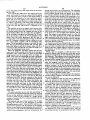
FIG. I is an isometric, somewhat simpli?ed view of
apparatus for the practice of one embodiment of this
shaft of the flow meter, is used to generate signals for
the counters. In either event, the counter and register
invention;
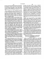
FIG. 2 is a block diagram of the major components of
one embodiment of the apparatus of this invention;
FIG. 3 is a block diagram of electrical circuitry asso
ciated with each dispenser according to one embodi
ment of this invention;
FIG. 4 is a block diagram of apparatus for receiving,
apparatus includes two shaft outputs, one of which
rotates at a speed proportional to the gallons register
and the other of which rotates at a speed proportional
to the dollars register.
According to the present invention, the functions
described hereinbefore are accomplished by apparatus
which includes pulse generators driven by the propor
tional dispenser register counter shafts, one pulse gen
erator producing pulses in proportion to the gallons
storing, processing, displaying and transmitting data
from the dispensers;
FIG. 5 is a perspective view of apparatus included at
the dispensers at a self-service station for converting
dispensed and the other producing pulses in proportion
rotary motion of the counting mechanism at the dis 25 to the number of dollars registered and displayed at the
pensers into electrical signals for transmission to a
dispenser. These pulses are transmitted to counters. A
central position at the station;
console is provided which includes a keyboard and
FIG. 6 is a sectional view of the apparatus shown in
various displays. The keyboard and displays are con
FIG. 5; and is taken substantially on the line 6-6 of
nected through a central processor unit, which forms a
30
FIG. 5;
part of a digital micro-computer, to various memory
FIG. 7 is a circuit diagram of’ certain stages shown on
storage locations. The operator may create a display of
a somewhat schematic basis in FIG. 3;
the number of gallons and the dollar amount of a sale
FIG. 8 is a circuit diagram of still other stages shown
which is in process or which has just concluded at any
on a somewhat schematic basis in FIG. 3; and
FIG. 9 is a circuit diagram of further stages shown on .
a somewhat schematic basis in FIG. 3.
DESCRIPTION OF THE PREFERRED
EMBODIMENTS
For the sake of simplicity and ease of understanding,
the preferred embodiments of this invention will be
described in terms of application of the invention to
selected dispenser by merely pressing the numbered
keys of the keyboard corresponding to the number of
the dispenser. The operator may also create a display of
the preceding sale for that dispenser by pressing a re
call key. The operator may also reset the dispenser for
another sale. Upon reset, both the pulse counters are
returned to zero, and the previous sale is stored in a
temporary memory for recall and display on the cosole.
Upon reset, the amount of the sale is also added to a
cumulative
total of sales stored in two separate memory
ent to those skilled in the art that the invention has
applicability to dispensing and sale of other liquid prod 45 locations, one of which is accessible to the station oper
ator and the other of which is accessible only to the
ucts and also of gas and solid products.
central of?ce. Means are provided by which the total
The description will also refer to an arrangement
amount in the first of these memory locations may be
involving a central of?ce and plurality of local service
read and written in a third memory location, as for
stations to which data is sent from a central office and
example at the end of each shift, so that the home
from which data is received upon interrogation by the
office can interrogate the station data system at any
central office. However, such various combinations
time during the succeeding shift and determine the
and sub-combinations of this invention are applicable
self-service gasoline stations, although it will be appar
to the individual service stations, where no central
of?ce is involved, therefore the invention should not be
considered to be limited to service stations which com
total of sales during the preceding shift.
The station data system also has a data entry mode in
55 which the station operator can enter data into some of
municate with the central of?ce.
the memory locations. For example, it may be desired
by the central of?ce that the station operator enter data
GENERAL DESCRIPTION
In the preferred embodiment of the invention which
will hereinafter be described in detail, apparatus is
reflecting a competitor’s selling prices, weather infor
mation, maintenance difficulties, personnel problems,
etc.
provided at a local station for controlling one or more
Means are provided for automatically entering data
gasoline dispensers, for receiving, displaying and stor
in selected memory locations re?ecting the amount of
gasoline in storage tanks at the station. such data being
provided, for example. by apparatus such as that dis
ing data on inventory of gasoline in storage tanks, for
transmitting this data and other data inserted by the
station operator to a central of?ce, and for transmitting 65 closed in the aforesaid co-pending application.
In the event of a power failure means is provided for
data from the central of?ce to the service station. The
term “gasoline dispenser" is used herein in preference
automatically protecting memory. In addition. the ap
to the term “gasoline pumpH because of the fact that in
paratus has an emergency shut-off function, whereby
4,033,883
5
6
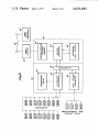
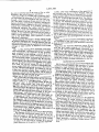
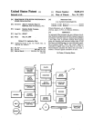
in H0. 2 the major components of the apparatus of
the station operator can, in the event of fire or other
this invention are shown in block diagram. Thus 16
emergency, shut off all dispenser operations.
different dispensers are shown, numbered 24-1 through
24-16, and four different level sensors and transmitters
are shown, numbered 25-] through 25-4. The dispens
The central office is provided with a computer which
can interrogate the memories of the station computer,
through a conventional telephone line and data cou
pler, and obtain a readout of data stored in any of the
memory locations of the station computer. During such
interrogation a lamp is lighted on the station console to
indicate that transmitting is in progress. During the
transmitting operation the station operator cannot
enter data or recall sales information from temporary
storage. However, he can temporarily interrupt trans
mission to reset dispensers and recall previous sales in
order to receive payment. Thus even during interroga
tion by the home of?ce, some operation of station
dispensers is permitted.
in the following description a service station having
16 gasoline dispensers and four gasoline storage tanks
will be discussed. However, it will be apparent that the
apparatus and system may be modified as necessary for
a larger or lesser number of. dispensers and storage
tanks.
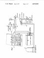
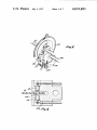
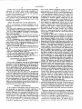
FIG. I of the drawing shows pictorially, and some
ers are provided with fuel by one or more submerged
pumps 52. The dispenser electronic system 54 is con
nected to receive signals from the dispensers and also
to feed signals to the dispensers. In addition, the dis
penser electronic system provides signals to energize
the submerged pumps so that gasoline may be pumped
to the dispensers when required. As will later be ex
plained, means are also provided for selectively operat
ing the dispensers independently of the electronic sys
tem, so that a signal may be sent directly from any one
of the dispensers to the submerged pump to cause it to
operate.
The output of the level sensor transmitters is received
and processed in the level sensor computer 56, one
form of which is disclosed in the aforesaid co-pending
application.
Data from the dispenser electronic system 54 and
from the level sensor computer are fed through an
interface 58 which provides suitable connection to a
what schematically, a preferred embodiment of equip
ment comprised in the apparatus of this invention.
digital microcomputer 60 and keyboard and display
apparatus 62. The digital computer 60 communicates
Thus, as shown in this drawing, a console 10 is con
nected to an electronic cabinet 12 and to a data cou
with a home office computer 64 see FIG. 2) through a
communication interface modem 61 and a conven
pler 14. The data coupler, in the embodiment shown. is
tional data coupler 14, as by means of the telephone
connected directly into a telephone line 16. The elec
tronic cabinet is provided with power for a power sup
line 16 or by means of radio transmission or the like.
ply unit 18 which converts and regulates power input
from both 110 volt AC source 20 and an auxiliary
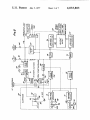
DISPENSER ELECTRONICS
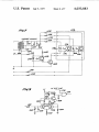
FIG. 3 shown schematically and in block diagram the
electrical circuitry utilized in the operation and moni
power supply which may comprise a rechargeable bat
tery 22, which provides power to protect the memory 35 toring of a single dispenser 24. The same or similar
circuitry is used with each of the other dispensers.
in the event of a power failure. An ordinary 8 volt wet
As previously noted, the dispenser 24 contains en
cell may be used, for example. Data is supplied to the
coders
48 and 50 which, in the preferred embodiment,
electronic cabinet from the dispensers, one of which'is
comprise perforated discs 60, 67 mounted on output
illustrated at 24, and from the level sensors and trans
mitters, one of which is shown at 25.
40 shafts on the dispenser counter (not shown) for rota
tion so that the perforations of each disc pass between
a light emitting diode (LED) 68 and a photo transistor
69 , each LED and photo transistor forming a
photocoupler which is used as an encoder in the pre
form of this invention. Other types of encoders
positions, “pump control“ and “data entry". A panel 45 ferred
known in the art may be used, as for example, the type
light 30 is provided for indication of the existence of
which utilizes rotating magnets and a reed switch, but
transmission from the station to the central office, and
The console 10 is provided with a conventional key
board 26, having keys number from 0 to 9, and keys
labeled “reset", "*”, “emergency stop", “enter", “re
call" and “clear”. A key operated switch 28 has two
a panel light 32 is provided for indication of transmis
sion of new data from the home office to the station. A
“shift-change" push-button is provided at 33, and a
“transmit-interrup" push-button is provided at 31.
A plurality of “ready" and “in-use" panel lights 34
the perforated disc type encoder just described is pre
ferred for its accuracy. A variety of photocouplers are
50 available on the market which are suitable for use in
this application. One example of such a photo coupler
is that manufactured and sold by Spectronics, Inc., as
Part Nos. SD-l440-3 and SE-l450-3.
and 36, respectively, are provided, one for each gaso
Pulser drivers 70, 71 are connected to the photocou
line dispenser. The console also has provision for dis
plers, providing an output current to the LEDs and
SS
play of three different numbers at 38, 40 and 42. At
receiving, amplifying and transmitting pulses from the
location 38 two numerals may be displayed, at location
photo transistors. The outputs from the pulser drivers
40 three numerals may be displayed, and at locaton 42
70, 71 are fed through the pulse shapers 72, 73, respec
five numerals may be displayed. The display may utilize
tively, which are basically Schmitt triggers. The pulse
conventional seven segment displays (light emitting
shapers introduce hysterisis into the signals in order to
diodes such as Monsanto‘s MAN-l0), nixie tubes or 60 reject electrical noice, and to compensate for un
any other suitable display device.
wanted mechanical jitter or vibration of the disks 66
The dispenser 24 has the conventional hose and noz
and 67. The output pulse trains from the pulse shapers
zle 44 and the conventional manual switch 46 which
are sent through gates 74, 75, respectively, and then to
must be turned on before any gasoline can be dis
the dollars counters 76 and the gallons counters 77.
65
pensed. In addition, the dispenser is provided with an
These preferably comprise decade counters which
encoder 48 to provide pulses indicative of the number
store the counts in 4-bit binary coded decimal (BCD)
of dollars of the sale and an encoder 50 to provide
pulses indicative of the gallons of gasoline dispensed.
form.
7
4,033,883
The dollars encoder 48 is preferably designed to emit
a pulse for each 0.00l dollars value of fuel dispensed,
and the gallons encoder S0 is preferably designed to
emit a pulse for each 0.0l gallon of fuel dispensed. In
order that the counters may count up to $99,999 and
up to 99.99 gallons, the dollars counters comprise ?ve
decade counters and the gallons counters comprise
four decade counters. Data is transferred from these
decade counters through a gating circuit 98.
It will be noted that although the gallons counter
provides four signi?cant ?gures, only three are pro
vided on the display. This issufficient for sales pur
poses, since customers are not interested in hundredths
of a gallon and the tenths digit is rounded up or down
to the nearest tenth. However, the totals stored in
memory are accurate to a hundredth of a gallon. Dol
lars are displayed to three decimal places, so that the
price charged can be adjusted to the nearest cent.
As is well known in the art, the counters in gasoline
dispensers must be reset to zero following each sale
before additional gasoline can be dispensed. The reset
is accomplished by means ofa manual switch adjacent
8
mission of any pulses generated after switch 46 is
opened, as may occur if this switch is opened while the
nozzle is dispensing gasoline. The in use output from
the delay network is sent to a lamp driver 90 which
illuminates one of the lamps 36 one the console to
inform the operator that this particular dispenser is
being used.
The in use indication is also sent to a triac gate 92.
The output of the triac gate is an enabling signal which
is sent through a photocoupler isolator 94, such as, for
example, General Electric Company's No. H1 1C1, to a
triac switch 96. The triac switch provides a connection
to ground for the reset motor circuit and relay coil 85
when the switch 80 is on automatic.
The in use signal to the pulser drivers 70 and 71,
serves as a control signal to enable the pulser drivers
(through an optical isolator that provides electrical
isolation to meet intrinsic safety requirements for haz
ardous environments.) The in use signal sets the ready
?ip-?op 100 to not ready, and the gate 102 which pre
vents a reset signal from setting the ready flip-flop 100.
The in use indication is also sent to the gates 74 and 75
to the nozzle receptacle, as shown at 46 in FIG. I. The
where it enables these gates and allows the pulses from
operation of this switch closes a circuit in which a reset
motor 78 (see FIG. 3) is connected, so that the reset 25 the pulse shapers 72 and 73 to be entered into the
motor runs to reset the counters to zero. The reset
motor shaft drives a cam which, when the dispenser
counters have been reset to zero, engages a normally
decade counters 76 and 77. The in use signal is gener
ated even when the switch 80 is on manual, therefore if
the dispenser is operated in the manual mode gener
closed switch 79 in the reset motor circuit, thereby
ated pulses will be counted at the counters 76, 77.
opening the switch so that the reset motor stops. Switch 30 Other components depicted in FIG. 3 will now be
79 is mechanically connected to a normally open
described although the function and operation of these
switch 82, so that when switch 79 is opened, switch 82
components will not be described in detail until after a
is closed. Switches 79 and 82 are also connected to a
description of the components shown in FIG. 4. Thus
manual switch 46, so that switch 79 is closed and switch
gating circuitry 98 is provided for reading out the
82 is opened when switch 46 is opened.
35 stored BCD count of the counters 76 and 77. A ready
According to the present invention, an additional
?ip-?op 100 receives as one of its inputs the in use
switch 80 is provided in the reset motor circuit. Switch
signal and as the other of its inputs a signal from gate
80 is a three-position switch which may be set at any of
102 which is enabled by a power on signal from circuit
“automatic“, “off" and “manual". When set at manual
I04, or by a “device select" signal accompanied by a
the reset motor circuit is grounded and the dispenser
reset signal when there is no in use signal present. After
may be operated in the normal manner, without being
a power failure, upon restoration of power the “power
reset from the console. When set at off the dispenser
up" circuit sends a pulse to all of the decade counters
may not be operated at all, and when set at automatic
the control system of the present invention becomes
effective.
When switch 82 is closed, in either the-manual or
automatic mode an “in use” signal is present in con
ductor 84. A tap 83 off this conductor to ground
through switch 80 contains a relay coil 85, which, when
an in use signal is present, holds relay switches 87
closed, to provide 220 volt AC to operate the sub
merged pump. The tap 83 also contains diode wired
“OR" gates 89 and 91, which are connected to corre
as 76, 77, to cause all outputs on the counters to read
zero. This is necessary, since whenever electrical power
45 is first supplied to the integrated circuits utilized in the
preferred embodiment, the output of the counters is
unpredictable.
The output from the ready ?ip-?op 100 is fed to a
ready lamp driver 108 to cause illumination of the
ready lamp 34 on the console, and is also fed as an
input to the triac gate 92. The third input to the triac
gate is the emergency stop input, supplied through
conduit I10.
sponding taps 83 of other dispensers of the same grade
of gasoline, so that a single relay coil 85 and switch 87 55
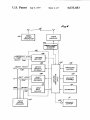
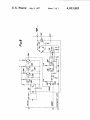
STATION ELECTRONICS
may be used with a single pump for each grade ofgaso
FIG.
4
depicts
the service station electronic system
line.
which is connected through the interface 58 to each of
An isolator comprising a photocoupler 86, such as,
the dispenser electronic systems, as depicted in FIG. 3.
for example, Monsanto's N0. MCTZE, provides electri~
cal isolation between the power line voltage level in
line 84 and the low logic voltage level of the remainder
of the circuit. The output of the photocoupler isolator
The heart of this sytem is a micro-computer system,
such as the MCS-4 produced by Intel Corp. of Santa
Clara, California and described in Intel’s User's Manual
dated March, I972. This set includes a central proces
is sent to a delay network 88 which produces an in use
sor unit 114, memory storage 116 and program control
output signal coincident with the in use signal at its
input, but which delays the cessation of the in use a 65 118. The central processor unit (CPU) communicates
with the home office through the communications in
short time (preferably approximately 1.5 seconds) rela
tive to the cessation of the in use signal at the input of
the delay network. This delay allows continued trans
terface
comprising
the
modulator-demodulator
(modem) 61 and the data coupler 14. The data coupler
may, for example, comprise a type 1001A CBS, avail
4,033,883
10
ing to the selected memory location, and then following
this by pressing keys corresponding to the data to be
entered. The enter key is then pressed to enter the data.
able on lease from the Bell Telephone Company, and
the modern may be a Tele-Dynamics Model 71 13B.
instructions are provided through the CPU from the
keyboard 26, as shown in H6. 1, and data selected for
display by the keyboard is decoded from BCD to deci
mal by the CPU and displayed, through the driver 122,
at the various displays of the console 10.
Preferably only two digits are provided for addressing
memory locations, so that the operator is limited to
addressing locations 0 to 99. Data in BCD form con
taining up to eight digits may be entered in the memory
To transfer the contents of a counter 76, 77 of one of
locations. In this mode of operation the program con
the dispensers or data from one of the tank lever sen
trol prevents any resetting of the dispensers and pre
sors 25 to the CPU, a data bus 124 is provided. Data l0 vents any read-out of data from the dispenser counters
transmitted is multiplexed to transmit one digit at a
or the level sensors, but the dispensers and dispenser
time, since speed of transmission is not important. The
counters are not inhibited from operation.
data bus consists of four parallel electrical signal con
in the data entry mode, various of the spare memory
ductors which are connected in a parallel electrical
manner; that is, each of the four conductors is electri 15 locations listed above may be designated for entry of
particular specified data. For example, memory loca
cally connected to each of the 16 output gates of the 16
dispensers, and to each of the four level sensors. Thus
the four signal conductors of the data bus transfer in
tion 0 may be used for the station telephone number or
parallel, simultaneously, the four-bit BCD output of
other identi?cation, and memory location 75 mayf be
used to show the selling price of a particular competi
either one of the counters or one of the level sensors. A
I01‘.
data bus driver 126 is provided for transfer of such data
As the keys are pressed, ?rst the memory location
identi?cation will appear at display 38 on the console,
and then the other data entered, which is at this point
held in temporary memory in the CPU, will appear at
into the CPU.
'
The counter or level sensor whose data is to be trans
mitted is determined by a “device select" signal which
is created by pressing identifying keys on the keyboard.
25
device select decoder 128, which decodes the signal
and produces an input device select signal to the dis
display indicates that the entry is wrong, it may be
removed by pressing the “clear" key. Data already in a
penser counter board or tank level sensor selected. The
CPU is programmed to multiplex transmission of data,
displays 40 and 42. The operator may thus check his
entry to be sure that it is accurate and then press the
enter key to enter the data in permanent memory. If the
The CPU, in response, feeds an identifying signal to the
30
and therefore sends a series of “digit select" signals to
memory may be displayed by addressing the appropri
ate memory location and pressing the “recall" key.
When the system is ?rst installed, it is desirable that
the accumulated dollars and accumulated gallons
the digit select decoder 132 which provides an output
signal through one of four digit select conductors 134.
A control bu?‘er 136 comprises a driver for signals
stored in memory locations 1 to 32 be identical to the
transmitted from the keyboard through the CPU, to 35 accumulated totals shown on the dispenser totalizer
provide an "emergency stop" signal through conductor
registers. This data is entered in memory for each dis
110 and a reset signal through conductor 140.
penser with the switch 28 turned to the data entry
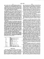
in a data system for 16 gasoline dispensers and four
mode. Thus for dispenser 10 the number 10 is first
gasoline storage tanks, a memory having, for example,
designated by means of the keyboard so that the num
160 memory locations will provide adequate capacity. 40 ber 10 appears at display 38. Keys corresponding to the
Each location should be capable of storing eight BCD
number of dollars shown on the dispenser register are
digits of 4 bits each, i.e. 32 bits. Memory locations may,
then pressed, this total number being displayed at dis
for example, be used as follows:
0
Spare
1-16
accumulated dollars for each of 16
dispensers
17-32
plays 40 and 42. When the numbers are checked, the
enter key is depressed to enter these in memory.
45
Memory location 26 is then addressed and keys cor
responding to the number of gallons accumulated on
the dispenser register are depressed and this amount is
entered. When all dispensers are initialized, key switch
accumulated gallons for each of 16
dispensers
33-36
37
3111-74
75-106
107-1 10
1 l1
l l2-l27
gasoline levels in each of four
storage tanks
spare
data read from locations 1-37 at
end of shift
spare
gasoline levels in each of four
storage tanks
spare
accumulated dollars for each of lo
28 may then be turned to pump control and the system
is ready for operation. The program control prevents
the entry of any data from the keyboard in the pump
control mode.
Initially, each dispenser must be reset to prepare the
dispenser
for operation. The initial power up causes the
55
delay circuit 88 to emit an in use signal for a short
dispensers
128-143
144-159
period, thereby turning the ready ?ip-?op 100 to not
temporary storage. dollars. for recall
temporary storage, gallons, for recall
OPERATION
ready. Thus it is necessary to reset each dispenser by
depressing keys on the console corresponding to the
60 numbers of each of the dispensers, in each case fol
lowed by pressing the reset key. The power up circit
will initialize the counters to all zeros and the data
stored in memory locations 1-32 will not be disturbed
The system of this invention has two modes of opera
tion, i.e. “pump control" and “data entry”, as deter
mined by the switch 28 on the console. A lock switch is
preferred to prevent entry of data by unauthorized
persons. In the data entry mode program control pro
vides that the station operator may enter data at any of
memory locations 0 to 99 by pressing keys correspond
65
by resetting the dispensers. In the pump control mode
the pressing of keys corresponding to a particular pump
number provides, through the CPU and the device
select decoder 128, a device select signal which is sup
plied to the output gates 98 of the selected dispenser
11
4,033,883
12
and to the gating circuit 102 which turns on the ready
storage tank sensors can be monitored. The addresses
?ip-flop 100.
of these inputs are stored in binary form, so a ?ve bit
binary address format which can handle up to thirty
two separate addresses is used to address these twenty
The ready ?ip-?op 100 is set to not ready by an in use
signal, and is reset to ready by a signal from the gating
circuit I02. This gating circuit, as previously noted, is
inputs. A device select decoder 128 comprising a 5-to
20 decoder selects one of the sixteen dispensers or one
enabled by the presence of a reset and device select
signal with no in use signal, or by a power up signal.
This switches the ready ?ip-?op to a ready state so that
of the four tank level sensors for reading into the CPU.
This signal enables the four output gates 98 of the
particular selected device, which follow the four bit
an output is provided to the ready lamp through the
lamp driver 108. In addition, a ready signal is provided
parallel BCD data from a particular counter enabled to
be read. But in the preferred embodiment, in order to
transfer out the four bit parallel BCD data, a digit select
signal must be present also. The digits are selected in
to the triac gate 92, which allows a dispenser to be
used.
The initiation of an in use signal, which occurs when
sequence by the program control. Thus, for selecting
switch 82 is closed after the reset motor cycle initiated
by closing manual switch 46, changes the state of the
ready ?ip-?op 100 to the not ready state. In addition,
the in use lamp is energized, and the gates 74, 75 lead
ing to the decade counters 76, 77 are enabled so that
pulses from the pulse generators 48, 50 may be
5
which of the nine decade counters in counters 76, 77 is
to be read out, a 4-to-l0 digit select decoder 132 is
used. The output of each decade counter is a four bit
BCD word which represents one of the nine decimal
digits contained in the nine counters. The four bit out
counted. The in use signal also has an input to the triac 20 put is read simultaneously in parallel from the selected
counter. Likewise, a four bit parallel output is available
gate 92. This gate is enabled if there is either an in use
from each tank level sensor.
or a ready signal, together with no emergency stop
it should be noted that although both a device select
signal. The in use signal continues to activate the triac
and a digit select must be sent to a dispenser counter
gate 92, the photocoupler isolator 94, and the triac
switch 96. When switch 82 is closed, relay coil 85 is 25 board in order to transfer data to the data bus for trans
mittal to the CPU, neither signal is required to operate
activated so that switches 87 are closed to supply cur
the dispenser or for the counters to receive and count
rent to the submerged pump motor.
encoder pulses.
When the dispenser operation ceases and the cus
While a sale is in progress, or after the sale is com
tomer turns off the manual switch 46, the in use signal
disappears, after a short delay, by virtue of switch 82 30 pleted but before reset, the amount of the sale can be
being opened, and the triac gate 92 is no longer en
abled. Thus once the dispensing has been completed
displayed by depressing the keys identifying the partic~
ular dispenser. The program control thus causes device
select and digit select signals to be supplied to the out
put gates 98 for reading of the contents of the counters
CPU. The triac switch remains open because the ready 35 76, 77, but no data is transferred to memory. Upon
for one sale, the triac switch 96 will open and will re
main open until a reset command is received from the
reset the program control causes the totals in the
?ip-?op is not reset to ready until the reset command is
counters to be added to the contents in memory of
received. The mere closing of manual switch 46 will not
memory location 1 to 32 for the particular dispenser;
provide an in use signal because the triac switch is open
At the same time the dollar amount in the counter 76 is
and therefore the reset motor circuit is not closed to
ground. Thus, once the triac swich opens, there must 40 added to the amount in the appropriate memory stor
age of addresses 112 to 127. In addition the amounts in
be a reset command generated by the CPU to reset the
the counters are temporarily stored in the appropriate
ready ?ip-flop and thereby enable the triac gate, which
ones of memory locations 128 to 159.
then closes the triac switch before the dispenser can
again dispense fuel. The reset command is initiated by
Then by pressing keys corresponding to the dispenser
a key on the keyboard, but it is not sent to the ready 45 number and the recall key, the amount of the previous
sale can be displayed.
?ip-?op by the CPU until the contents of the decade
Upon completion of the next sale and an additional
counters 76, 77 have all been transferred by means of
reset, the amounts in the temporary storage are re
the data bus 124 to the CPU. When this transfer has
placed by the amounts of the new sale.
occurred, the CPU‘ issues the reset command to the
gating circuit I02 and thus to the ready ?ip-?op, 50 An emergency stop command is received by the con~
thereby providing an enabling signal to the triac gate
and closing the traic switch, and to the counters 76, 77
to reset them to zero. Thus the reset command both
resets the counters and returns the dispensers to the
ready state.
To reduce electrical power and data processing re~
quirements, the operational format of the CPU selected
trol buffer 136 whenever the operator depresses the
emergency stop key on the keyboard. Whenever this
occurs the triac gate is inhibited, thereby causing the
triac switch to open. The emergency stop command is
55 sent to all dispenser counter boards simultaneously.
Electrical power is supplied to the relay coil 85
through OR gate 89 from any dispenser of the same
grade. Thus the relay coil 85 activates the switches 87
for use in the preferred embodiment of the present
and the submerged pump whenever any dispenser of
invention reads out the contents of a single decade
counter of counters 76, 77 at a time and from only one 60 the same grade is operated. OR gate 91 is used to allow
each reset motor to be controlled independently, but
dispenser at a time.
not disable the relay coil 85 is another dispenser of the
The readout and reset of the counters 76, 77 upon
same grade is in operation. lf an emergency stop com~
mand is issued by the CPU. all triac switches are
through program control. Thus the CPU selects a par
ticular device address code in response to the pressing 65 opened to disable all submerged pumps.
The submerged pump motor is also cut off if none of
of keys on the keyboard identifying the device which is
the dispensers is in use. As explained above, after the
being reset. For the preferred embodiment disclosed, a
pressing the reset key on the keyboard is provided
total of sixteen dispensers and four underground fuel
dispensing operation is completed for each sale, neither
13
4,033,883
14
through a data-coupler and, for example, a telephone
the ready nor the in use signal is present at the input of
the triac gate to enable it and therefore the triac switch
for that dispenser opens. Hence, if none of the dispens
line. The home office computer is programmed to tele
phone the station and, after identifying signals, transmit
a “transmitting" signal to the station computer. By
ers for one grade of gasoline is in use, then all triac
switches for those dispensers are open and the sub
program control, a XMTG light 30 is illuminated on the
console, and the CPU, keyboard, and related station
equipment is inhibited from operation. However, the
merged pump motor for that grade of gasoline is turned
off.
Upon completion of a sale at a dispenser, the station
operator may determine the amount of the sale in order
dispensers and their counters may continue to operate.
The station operator may interrupt transmission for a
limited time e.g. l5 seconds, if desired for the purpose
of displaying a sale, resetting a dispenser or recalling a
to receive payment by merely pressing keys corre
sponding to the dispenser number. For example, to
display the amount of the sale just completed at dis
penser 24-10, the operator addresses 10, Under pro
gram control, this produces a display of the dispenser
previous sale. This is accomplished by pressing the
transmission interrupt push-button 31 on the console.
Through program control, the home office computer is
number (10) and the totals of both of the counters 76 15 instructed to stop transmitting. Transmission automati
cally resumes at the end of the transmission interrupt
and 77 for dispenser 24-10.'
period.
If a new customer wishes to use the dispenser before
In the event of any emergency, e.g. fire, gasoline
spillage, severe Windstorm, etc., the station operator
payment has been received for the last sale, the dis
penser and its counters may be reset to zero by pressing
reset key. This causes the totals in the counters 76 and
has the capability of completely shutting down all dis
pensers and pumps, without disturbing memories, by
77 for dispenser 24-10 of the above example, to be
stored in temporary memory locations 137 and 153,
respectively, following the scheme of memory locations
control, this causes the CPU to send a pulse to the triac
gate 92, disabling the gate so that no signal is sent to the
keys addressing the particular dispenser, and then the
20
pressing the Emergency Stop Key. Under program
shown on page 21, and also causes these totals to be 25 triac switch 96, and the switch is thus opened.
The home office computer may also enter data in the
added to the accumulated totals in memory locations
10 and 26, respectively. The dollars count from
counter 76 for dispenser 24-10 is also added to the
accumulated total in memory location 121 as described
earlier. The previous sale can then be recalled from 30
temporary storage by pressing the dispenser number
and the recall key, and the gallons and dollars of the
previous sale is thereby displayed.
In a preferred embodiment of the invention, program
memory of the station computer. When doing so, the
home office computer transmits a signal to illuminate
the “new data" light 32 on the console. After transmis
sion, such data may be viewed by the station operator
by pressing keys to address the appropriate memories,
and pressing the recall key. The new data light may be
turned off by pressing the key marked *.
The program control involves only conventional op
control causes the displays 38, 40 and 42 to blink if 35 erations, familiar to computer programmers; therefore
it is not necessary to set forth the program herein. The
keys are pressed in the wrong order to two keys are
invention does not lie in the program, but in the control
pressed at the same time. The display may be cleared at
and data system itself, particularly as applied to self
any time by merely pressing the clear key.
service
gasoline stations, and various chain operations,
The operator may determine the amount of fuel in
any of the storage tanks by switching to the data entry 40 some of which may use only the manual data input and
made and then pressing keys addressing the memory
telephone communications.
locations of these storage tanks (e.g. one of locations
DETAILS OF COMPONENTS AND STAGES
33-36) and pressing the recall key. This will cause the
PREVIOUSLY DESCRIBED SOMEWHAT
display of the amount of fuel in the selected storage
SCHEMATICALLY
45
tanks.
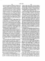
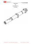
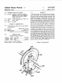
FIGS.
5
and
6
illustrate apparatus for converting
In a preferred embodiment of the invention, the re
mechanical indications provided by the encoders 48
spective signals from the level sensors are interpreted
and 50 in FIG. 1 to electrical signals digitally represent
and indicator lights on the console panel are energized
ing such mechanical indications. For example, as the
to display low inventory and water in tank warnings.
encoder 48 is rotated to indicate the monetary value
The level sensor is disclosed in full detail in co-pending
application Ser. No. 388,593.
(price) of the product dispensed by the dispenser 24
and its mechanical computer, the apparatus shown in
FIGS. 5 and 6 is operated to produce electrical pulse
signals. The pulses are counted which represents the
value of ?uid dispensed. Similar apparatus to that
shown in FIGS. 5 and 6 may be provided to produce
central office. Thus, to provide a check on the data in
electrical pulse signals which represents the volume
memory locations l-16 and 33-36, to determine
(gallons) of such product dispensed as indicated by the
whether any erroneous data has been entered, redun
encoder
50.
dant memory locations 112-127 and 107-110 are pro
As shown in FIGS. 5 and 6, the rotary disc 66 (also
60
vided.
shown in FIG. 3) is mounted on the dollars rotary shaft
At the end of a shift, or at other times as desired, the
49 of the dispenser mechanical computer by means of
data stored in memory locations 1-37 may be read and
set screws 67 for rotation with the shaft, and is pro
written in memory locations 38-74. This is accom
As previously noted, the operator may enter data in
any of memory locations 0-99, and data is temporarily
stored in locations 128 to 159 for recall. However,
memory locations 100-127 are accessible only to the 55
plished through program control by pressing pushbut
vided with equally spaced apertures 202 around its
for reading at any time during the succeeding shift.
As previously noted, communication with the home
disc 66 at the hub on both sides, and supports a re
ton 33 on the console. This data is therefore preserved 65 periphery. A forked frame 204 embraces the rotary
office computer is performed in a conventional manner
placeable slotted block 206 at the periphery of the disc
66. A frame anchoring brace 208 is ?xed to a stationary
15
4,033,883
pin 210 of the dispenser mechanical computer at one
end and is attached at the other end as at 209 to the
forked frame 204 in pivotal relationship to the frame.
The light-emitting diode 68 (also shown in FIG. 3) is
disposed in a mounting hole in one side of the replace
ting diode 248, one terminal of which is grounded and
the other terminal of which is connected through a
resistance 250 to receive a positive voltage of relatively
low magnitude such as approximately +5V.
A positive voltage of relatively low magnitude is in
able block 206, as shown in cross-section in FIG. 6, and
the transistor 69 (also shown in FIG. 3) is similarly
disposed in the opposite side of the block 206 to face
the diode across the slot. The block 206 is indexed and
affixed to the frame so as to position the diode and
transistor at the radial position of the apertures 202 in
the disc 66. In this way an electrical signal is produced
by the transistor 69 as each aperture 202 moves be
tween the diode 68 and the transistor 69. This signal is
introduced through leads to the gates 74 and 75 and to
the counters 76 and 77. These digital signals represent
progressive increments in the price of the product dis
16
terminal of the transistor 246 is connected through a
resistance 248 to the cathodes of the diodes 222 and
224. The transistor 246 is associated with a light-emit
troduced through the resistance 250 to the diode 248
when an in use signal is produced. This causes the
transistor 246 to become conductive so that a positive
voltage is introduced to the base of the transistor 244.
This positive voltage causes the transistor 244 to be
come conductive so that a ground potential is effec
5
tively introduced to the diodes 68a and 68b, and causes
the diodes to emit light. As ?ow of product thru the
dispenser causes successive apertures 202 in the disc
pensed by the dispenser.
66 to move between the diode 68a and the transistor
The light-emitting diode 68 and the transistor 69 are
schematically shown in FIG. 7 as 68a and 69a for the
encoder 48 (FIG. 1) to distinguish them from corre
encoder S0. The diode 68a and the transistor 690 are
shown in FIG. 7 as being enclosed within a box 216 in
690, the photo-sensitive transistor 69a detects the
resulting intermittent light beams. The transistor 69a in
turn becomes intermittently conductive and passes the
signals for the dollars count through the resistor 240. In
like manner and simultaneously, the transistor 69b
passes signals through the resistor 242 when the diode
broken lines, this box corresponding to the block 206
shown in FIGS. 5 and 6 and described above. Similarly,
indicate increments in the volume (gallons) of the ?uid
a diode 68b and a transistor 69b are associated with
dispensed for the individual dispenser. The circuitry
sponding elements shown in FIG. 3 for the “gallons"
68b becomes conductive and with rotation of disc 67 to
each other in a relationship corresponding to the diode
shown in FIG. 7 may be considered to correspond to
68a and the transistor 69a to produce signals corre
the diodes 68, the transistors 69 and the pulser drivers
sponding to increments in the volume (gallons) of the 3O 70 and 71 in FIG. 3.
?uid dispensed in an individual dispenser.
The signals passing through the resistor 240 are intro
The diodes 68a and 68b are adapted to receive volt
duced in FIG. 3 to a pulse shaper 72 which is shown in
age from a full-wave recti?er formed in part by a pair of
some detail in FIG. 9. The resistor 240 in FIG. 7 is also
diodes 222 and 224 and the secondary winding of a
indicated in FIG. 9 to show that the electrical signals
shielded transformer 226. The primary winding of the
representing increments in the dollar amount of the
transformer 226 is connected to receive an alternating
product dispensed by an individual diepenser is intro
voltage such as US volts from a commercial source.
duced to the base of a transistor 250 and to ?rst termi
The transformer 226 is constructed (or shielded) to
nals of a parallel network formed by a resistor 252 and
a capacitor 254, the other terminals of which are
between the primary and secondary windings of the 40 grounded. The transistor 250 is included in a differen
transformer, thereby preventing undesirable voltages
tial ampli?er with a transistor 256. The emitters of the
from being introduced to the elements 68a, 68b, and
transistors 250 and 256 have a common connection
6912. Thus the transformer is one protective element in
with one terminal of a resistor 258, the second terminal
make certain that short circuits can never be produced
this intrisically safe (from vapor ignition), low energy
of which is grounded. The base of the transistor 256 is
circuit.
45 connected to one terminal of a resistor 260, the second
The anodes of the diodes 222 and 224 are connected
terminal of the resistor being grounded.
to the end terminals of the secondary winding of the
The collectors of the transistors 250 and 256 respec
transformer 226 and the cathodes are connected to a
tively receive positive voltage through resistors 262 and
resistance 228 and'capacitances 230 included in the
full-wave recti?er. Second terminals of the resistance
264 from a source providing a positive voltage of low
magnitude, such as approximately +5V. Signals on the
228 and the capacitances 230 are connected to the
center tap of the secondary winding of the transformer.
collector of the transistor 256 are also introduced
through a coupling capacitor 266 to the base of a tran
Connections are made from the cathodes of the diodes
sistor 268. A positive potential of relatively low magni
222 and 224 to ?rst terminals of resistances 232, 234,
tude is also introduced to the base of the transistor 268
236 and 238, second terminals of which are respect 55 through a resistor 270. The emitter of the transistor
fully connected to ?rst terminals of the diode 680, the
268 is grounded and the collector of the transistor 268
diode 68b , the transistor 69a and the transistor 69b.
Second terminals of the transistors 69a and 69b are
has positive potential applied to it through a resistor
272. The signals on the collector of the transistor 268
respectively connected to output leads through resis
tances 240 and 242. All resistances 232, 234, 235, 238,
are introduced to one terminal of “NAND” network
274 having another terminal connected to a line 276 to
240 and 242 are protective elements and are included
receive the in use signals.
The transistor 256 is normally conductive and the
in the circuit to limit the electrical energy entering
hazardous area 223 of the dispenser to intrinsically safe
levels (non-ignition of ?ammable vapors).
Second
nected to
of which
nected to
transistor 250 is normally nonconductive. When the
transistor 69a in FIG. 7 becomes conductive to indicate
terminals of the diodes 68a and 68b are con 65 an increment in the dollar amount of the product dis
the collector of a transistor 244, the emitter
pensed by the individual dispenser, it causes a positive
is grounded and the base of which is con
signal to be introduced through the resistor 240 to the
one terminal of the transistor 246. A second
base of the transistor 250 in FIG. 9. This causes the
17
4,033,883
18
pler is amplified in stages which include transistors 280,
282, 284 and 286. A delay indicated in block form at
88 in FIG. 3 is provided at the output of the stage in
cluding the transistor 282 by including a resistor 288
transistor 250 to become conductive. The resultant
decrease in the potential on the collector of the transis'
tor 250 is introduced to the base of the transistor 256 to
make the transistor 256 nonconductive. By way of
illustration. the transistor 250 becomes conductive and
and a capacitor 290 in series and connecting the com
mon terminal between the resistor 288 and the capaci
tor 290 to the collector of the transistor 282 and the
the transistor 256 becomes nonconductive when a sig
nal having an amplitude of at least approximately 3.4
volts is introduced to the base of the transistor 250.
The resistor 262 has a considerably greater value
than the resistor 264. Because of this, the voltage pro
base of the transistor 284. As previously described, this
delay in dropping the in-use condition, and the asso
ciated pulse counting capability is desirable to make
duced on the emitter of the transistor 250 during the
certain that a user does not obtain a small amount of
conductivity of this transistor is closer to ground poten
tial than the voltage produced on the emitter of the
transistor 256 while it is conducting. As a result, the
free (uncounted) product (in the order of 2 or 3 cents
worth) after he turns off the pump in the dispenser.
transistor 250 remains conductive even when the volt
age introduced to the base of the transistor falls consid
the capacitor 290 is sufficiently short so as to prevent
the dispenser user from turning off the dispenser to
reset the dials to zero, and the restarting to dispense
However, the delay provided by the resistor 288 and
erably below a potential of approximately 3.4 volts.
This prevents spurious signals passing through the resis
product again before the in-use condition is lost.
tor 240 to the base of the transistor 250 from triggering
The output signal on the collector of the transistor
the transistor 250 to a state of nonconductivity. By way 20 286 is introduced to a cathode of a diode 292 which is
of illustration, the transistor 250 becomes triggered to
a state of nonconductivity only when the voltage intro
included in an “AND" network with a diode 294. The
duced to the base of the transistor falls below a value of
ready (compliment of ready) signal from the “ready"
approximately 0.9 volts.
By preventing the transistor 250 from being triggered
cathode of the diode 294 is connected to receive the
25
to a state of nonconductivity until the voltage on the
base of the transistor has fallen to a level considerably
lower than that required to trigger the transistor to a
state of conductivity, the transistor 250 is made insensi
?ip-?op I00 in FIG. 3. The AND network formed by
the dioded 292 and 294 produces a low voltage when
either an ln-use signal is not introduced to the diode
292 or a ready signal is not introduced to the diode
294. At such times as an in use signal and a ready signal
tive to spurious signals such as noise signals. In this 30 are simultaneously being produced, a high voltage is
obtained from the anodes of the diodes.
way, the transistor 250 responds only to large signals
The voltage on the anodes of the diodes 292 and 294
representing increments in the dollar amount of the
is introduced to the base of a transistor 296 which is
included in an “NOR" network with a transistor 298.
product dispensed by the individual dispenser. The
effective hysteresis also prevents undesirable extra
signals from being generated from mechanical vibra~
35 The emitters of the transistors 296 and 298 are
tions and slight reverse motions of the disk when other
wise in a static condition near one of the signal thresh
old levels.
Every time that the transistor 250 is triggered to a
state of conductivity and is then triggered to a state of 40
grounded and the base of the transistor 298 is con
nected to receive the emergency stop signal. The col
lectors of the diodes 296 and 298 are connected to the
light-emitting diode in the photocoupler isolator 94
also illustrated in FIG. 3.
The AND network formed by the diodes 292 and 294
and the NOR network formed by the transistors 296
and 298 correspond to the triac gate 92 in FIG. 3. As
nonconductivity, the transistor 256 becomes alter
nately nonconductive and conductive. When the tran
sistor 256 becomes conductive, a relatively low poten
previously described,a described, a voltage is produced
tial is introduced from the collector of the transistor
256 to the base of the transistor 268. This causes the 45 on the anodes of the diodes 292 and 294 when either an
in use signal or a ready signal is produced. This low
transistor 268 to become nonconductive so that a rela
voltage is introduced to the base of the transistor 296 to
tively high potential is introduced to the NAND net
turn off the transistor. The transistor 298 is also turned
work 274. The NAND network 274 then passes this
o?‘ when an emergency stop signal is not being intro
signal provided that a positive voltage is produced on
the line 276 to indicate that the dispenser is in use.
50 duced to the base of the transistor 298. Under these
conditions, a high voltage is produced on the collectors
Therefore, when the in-use condition exists, each
of the transistors 296 and 298 to make the diode in the
successive cycle of triggering the transistor 250 in se
photocoupler isolator 94 conductive. This in turn
quence to a state of conductivity and then a state of
causes a silicon-controlled rectifier 94a in the isolator
nonconductivity produces one incremental count in the
dollar amount of the product dispensed by the individ
ual dispenser. Similar circuitry to that shown in FIG. 9
is provided and is operative to produce signals from
transistors 68b through resistor 242 representing incre
ments in the volume (gallons) of product dispensed for
the individual dispenser. Typically, the increment for
the amount of ?uid dispensed is 0.01 gallon and the
monetary increment is 0.001 dollar.
55 94 to become conductive.
When a voltage is produced in the silicon-controlled
recti?er 940, it causes a positive voltage to be produced
in a diode bridge 300. This positive voltage in turn
causes a switch formed by a back-to-back relationship
60 of two silicon-controlled recti?ers to become conduc<
tive. This switch is designated as the triac switch 96 in
FIG. 3. When the switch 302 becomes conductive, it
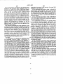
FIG. 8 illustrates in some detail the construction of
causes the ground path to be completed to the reset
the photocoupler 86, the delay circuit 88, the triac gate
motor and the relay coil which activates the submerged
92, the photocoupler isolator 94 and the triac switch 96 65 pump motor for supplying the product from the stored
in FIG. 3. In FIG. 8, the “in use" signal is introduced to
tanks. Power is not applied to the reset motor until
the photocoupler 86 also shown in FIG. 3. The resul
switch 46 is activated to turn the dispenser on to dis
tant signal produced by the transistor in the photocou
pense product.
19
4,033,883
20
determined increment in the amount of energy ?uid
The novel functions provided by the apparatus and
dispensed by the dispenser.
method of this invention allow complete control of
dispensers at a self-service station, with storing of data
2. The combination set forth in claim 1 wherein the
forked frame means supports a pair of spaced apart
in such a way that accuracy can be checked by a home
blocks embracing the path of said aperture orbit and
office, and the accounting function performed with
the photocell means include a light source disposed on
one of the blocks and a light detector disposed on the
other one of the blocks to provide said plurality of
automated data. Prior to or during a transaction, the
sales data from the previous sale on each dispenser can
be recalled and displayed. Reset of a dispenser is inhib
ited while the dispenser is in use. Additional data can
electrical signals.
3. The combination set forth in claim 2 wherein the
brace means are pivotable relative to the forked frame
means to facilitate the mounting of the brace means on
be entered manually by the station operator, electroni
cally by the home office. Automatically acquired digi
tal data received from tank inventory gauges can be
the second stationary shaft.
received, displayed, stored in memory with continual
updating, and transmitted by telephone. As will be
4. In combination in a dispenser at a gasoline station
for producing electrical signals representing the
apparent to those skilled in the art, many other advan
tageous results are realized from the apparatus and
method of this invention.
amount of energy fluid dispensed by the station, a ?rst
shaft operably connected to the dispenser for rotation
The preferred embodiments of the apparatus of this
gasoline dispensed by the dispenser, a second shaft
invention have been described as utilizing conventional
integrated and micro~computer circuits, and other ap
thereby in an amount correlated with the amount of
20
paratus suitable for use therewith, as well known in the
art. However, those skilled in the art will appreciate
having a stationary disposition, a disc mounted for
rotation on said ?rst shaft and having a plurality of
apertures equally spaced around the periphery of the
disc to provide indication as to the rotation of the disc,
that different micro-computer programs, logic systems,
?rst means embracing the disc and supported rotation
other types of circuits and different apparatus may be 25 ally free about the ?rst shaft, second means mounted
substituted without departing from the scope of the
on the second shaft for fixed disposition on the second
invention. The invention is not limited, therefore, to
shaft and operatively coupled to the ?rst means in
the speci?c embodiments shown and described, but
pivotable relationship to the ?rst means, and photocell
only as de?ned by the appended claims.
means disposed on the ?rst means and positioned rela
We claim:
30 tive to the apertures in the disc to produce signals in'
1. ln combination in a dispenser at a gasoline station
dicative of the quantum rotation of the apertures past
for producing electrical signals representing the
the photocell means.
amount of energy ?uid dispensed by the dispenser, a
5. The combination set forth in claim 4 wherein the
?rst shaft operably connected to the dispenser for rota
?rst means include a pair of blocks disposed on oppo
tion thereby in an amount correlated with the amount 35 site sides of the disc and the photocell means include a
of ?uid dispensed, a second stationary shaft displaced
light source supported by one of the blocks and a de
tector supported by the other of the blocks and posi
from the ?rst shaft, brace means mounted at one end
tioned relative to the light source to receive light pass
on the second stationary shaft, means de?ning a forked
ing through the apertures from the light source as the
frame mounted at one end on the ?rst shaft rotationally
apertures rotate past the light source.
free of the first shaft, the forked frame means being
6. The combination set forth in claim 5 wherein the
attached to the brace means at a position removed
light detector converts the pulses of light passing from
from the ?rst shaft and the second stationary shaft, a
the light source through the apertures to electrical
rotary disc supported on the first shaft between the fork
signals and there is included a remotely located signal
legs of the frame means for rotation with the ?rst shaft,
the rotary disc having a plurality of uniformly spaced 45 accumulator and transmitting means for transmitting
the generated signals of said light detector to said accu
apertures provided in an annular path of orbit near its
mulator for the accumulation of data represented by
periphery, and photocell means disposed on the frame
the signals.
for scanning the apertures in the disc rotates to provide
1"
‘I
ll‘
it
Il'
a plurality of electrical signals each representing a pre
55
65