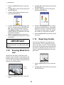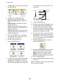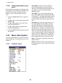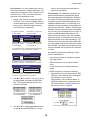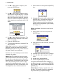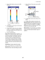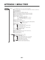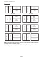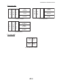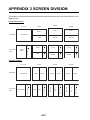
1
Back
OPERATOR'S MANUAL
COLOR LCD SOUNDER
MODEL
FCV-295
www.furuno.co.jp
The paper used in this manual
is elemental chlorine free.
・FURUNO Authorized Distributor/Dealer
9-52 Ashihara-cho,
Nishinomiya, 662-8580, JAPAN
Telephone : +81-(0)798-65-2111
Fax
: +81-(0)798-65-4200
All rights reserved.
Printed in Japan
A : MAY 2008
B : FEB . 02, 2009
Pub. No. OME-23760-B
(AKMU )
FCV-295
*00016850811*
*00016850811*
* 0 0 0 1 6 8 5 0 8 1 1 *
IMPORTANT NOTICES
General
• The operator of this equipment must read and follow the descriptions in this manual. Wrong operation or maintenance can cancel the warranty or cause injury.
• Do not copy any part of this manual without written permission from FURUNO.
• If this manual is lost or worn, contact your dealer about replacement.
• The contents of this manual and equipment specifications can change without notice.
• The example screens (or illustrations) shown in this manual can be different from the screens
you see on your display. The screens you see depend on your system configuration and equipment settings.
• Save this manual for future reference.
• Any modification of the equipment (including software) by persons not authorized by FURUNO
will cancel the warranty.
• All brand and product names are trademarks, registered trademarks or service marks of their
respective holders.
How to discard this product
Discard this product according to local regulations for the disposal of industrial waste. For disposal
in the USA, see the homepage of the Electronics Industries Alliance (http://www.eiae.org/) for the
correct method of disposal.
How to discard a used battery
Some FURUNO products have a battery(ies). To see if your product has a battery(ies), see the
chapter on Maintenance. Follow the instructions below if a battery(ies) is used.
In the European Union
The crossed-out trash can symbol indicates that all types of batteries
must not be discarded in standard trash, or at a trash site. Take the
used batteries to a battery collection site according to your national
legislation and the Batteries Directive 2006/66/EU.
Cd
In the USA
The Mobius loop symbol (three chasing arrows) indicates that Ni-Cd
and lead-acid rechargeable batteries must be recycled. Take the used
batteries to a battery collection site according to local laws.
Ni-Cd
Pb
In the other countries
There are no international standards for the battery recycle symbol. The number of symbols can
increase when the other countries make their own recycle symbols in the future.
i
SAFETY INSTRUCTIONS
The operator and installer must read the applicable safety instructions before attempting to
install or operate the equipment.
WARNING
Indicates a potentially hazardous situation which, if not avoided,
could result in death or serious injury.
CAUTION
Indicates a potentially hazardous situation which, if not avoided,
can result in minor or moderate injury.
Warning, Caution
Prohibitive Action
Mandatory Action
WARNING
WARNING
ELECTRICAL SHOCK HAZARD
Do not open the equipment.
Do not put containers with liquids on
the top of the equipment.
Hazardous voltage exists inside the
equipment. Refer repair to authorized
service personnel.
Fire, electrical shock or injury can
result.
If you feel that the equipment is
acting abnormally, immediately turn
off the power at the switchboard.
Immediately turn off the power at the
switchboard if something is dropped
into the equipment.
If the equipment is excessively warm
or making strange noises, immediately
turn off the equipment at the switchboard.
Continued use of the equipment can
cause fire or electrical shock.
Immediately turn off the power at the
switchboard if the equipment is
emitting smoke or fire.
Keep the equipment away from rain
and water splash.
Fire, electrical shock or injury can
result if water leaks into the equipment.
Continued use of the equipment can
cause fire or electrical shock. Contact a
FURUNO agent for service.
Use the proper fuse.
Do not disassemble or modify the
equipment.
Use of an incorrect fuse can damage
the equipment and can cause fire.
Fire, electrical shock or injury can
result.
Do not operate the equipment with
wet hands.
Electrical shock can result.
ii
SAFETY INSTRUCTIONS
CAUTION
CAUTION
Do not transmit with the transducer
out of water.
Properly adjust the gain.
Too little gain may present no picture.
Too much gain shows excessive noise
on the picture. Using the depth data
for navigation when the gain is incorrectly
set can lead to a dangerous situation.
The transducer will be damaged.
Do not use depth information for
navigation while the picture advance
speed is set to "stop".
The data presented by this equipment
is intended as a source of navigation
information.
The depth indication is not refreshed
while the picture is stopped. Use of
depth data for navigation in this case
could lead to grounding or other
dangerous situation.
The prudent navigator never relies
exclusively on any one source of navigation information, for safety of vessel
and crew.
Do not handle the LCD's panel
roughly; it is made of glass.
Injury can result if the glass breaks.
Warning Labels
Warning labels are attached to the equipment. Do not remove the labels.
If a label is missing or illegible, contact a FURUNO agent or dealer about replacement.
WARNING
To avoid electrical shock, do not
remove cover. No user-serviceable
parts inside.
WARNING
To avoid electrical shock,
do not remove cover.
No user-serviceable parts
inside.
Name: Warning Label (2)
Type: 803-129-1001-3
Code No.: 100-236-743-10
Name: Warning Label (1)
Type: 86-003-1011-3
Code No.: 100-236-233-10
iii
TABLE OF CONTENTS
FOREWORD ........................................ v
SYSTEM CONFIGURATION .............. vi
1.
2.3
2.4
2.5
2.6
2.7
OPERATION ................................. 1
1.1 Control Description......................1
1.2 Power On/Off ..............................2
1.3 How to Adjust Display Brilliance
and Panel Dimmer ......................2
1.4 Selecting a Display......................2
1.4.1 Single frequency display......2
1.4.2 Dual frequency display ........3
1.4.3 Zoom display .......................3
1.4.4 User 1 and 2 displays ..........5
1.5 Selecting a Range.......................5
1.5.1 Range adjustment................5
1.5.2 Manual range adjustment ....5
1.6 Shifting the Range.......................6
1.7 Adjusting the Gain.......................7
1.7.1 Selecting gain adjustment....7
1.7.2 Manual gain adjustment.......7
1.8 Measuring Depth.........................8
1.9 Menu Operating Procedure.........8
1.10 Picture Advance Speed...............9
1.11 Rejecting Interference .................9
1.12 Erasing Weak Echoes...............10
1.13 Rejecting Clutter........................10
1.14 Adjusting TVG ...........................11
1.15 A-scope Display ........................12
1.16 Alarms .......................................13
1.17 FUNCTION Control ...................15
1.17.1 Using the FUNCTION
control ................................15
1.17.2 Programming
the FUNCTION control ......15
1.18 Waypoints .................................16
1.18.1 Entering a waypoint ...........16
1.18.2 Editing waypoints...............17
1.18.3 Erasing waypoints..............17
1.18.4 Setting destination
waypoint.............................18
1.19 Menu Description ......................18
1.19.1 Sounder menu ...................18
1.19.2 Tx/Rx menu .......................22
1.19.3 Display menu .....................22
1.19.4 Data menu .........................23
2.
3.
Range Menu .............................29
Key Menu..................................29
Language Menu ........................30
Units Menu................................30
Calib Menu................................30
MAINTENANCE &
TROUBLESHOOTING.................32
3.1
3.2
3.3
3.4
3.5
3.6
3.7
3.8
3.9
3.10
Maintenance .............................32
Care of Display Unit ..................32
Transducer Maintenance ..........32
Fuse Replacement....................33
LCD Backlight Life ....................33
Battery Voltage Alert .................33
Troubleshooting ........................33
Self Test....................................33
LCD Test...................................35
Restoring Default Settings ........35
MENU TREE .................................. AP-1
SCREEN LAYOUT ........................ AP-4
SCREEN DIVISION ....................... AP-7
SPECIFICATIONS ..........................SP-1
INDEX ..............................................IN-1
SYSTEM MENU .......................... 25
2.1 How to Open the System Menu 25
2.2 User Menu.................................25
2.2.1 User menu description.......25
2.2.2 Selecting data for nav data
displays..............................27
iv
FOREWORD
A Word to FCV-295 Owners
• In addition to the conventional gain setting,
Gain may be applied to the whole display.
Congratulations on your choice of the
FURUNO FCV-295 Color LCD Sounder. We
are confident you will see why the FURUNO
name has become synonymous with quality
and reliability.
• Alarms: Bottom, Fish (bottom lock and normal), Speed*, Water Temperature*, and Arrival*.
• Edge function of white marker traces the
bottom contour with a thin white line.
For over 60 years FURUNO Electric Company has enjoyed an enviable reputation for innovative and dependable marine electronics
equipment. This dedication to excellence is
furthered by our extensive global network of
agents and dealers.
• Zero line may be removed to look for fish
near the surface.
• User-programmable nav data displays provide analog and digital nav data.
• Waypoints (up to 20) for marking important
locations.
This equipment is designed and constructed
to meet the rigorous demands of the marine
environment. However, no machine can perform its intended function unless installed, operated and maintained properly. Please
carefully read and follow the recommended
procedures for operation and maintenance.
• Destination waypoint feature provides
range, bearing and time-to-go to destination waypoint.
* Requires appropriate sensors.
The TFT LCD is constructed using the latest
LCD techniques, and displays 99.99% of its
pixels. The remaining 0.01% of the pixels may
drop out or blink, however this is not an indication of malfunction.
We would appreciate hearing from you, the
end-user, about whether we are achieving our
purposes.
Thank you for considering and purchasing
FURUNO equipment.
Features
The FURUNO FCV-295 is a dual frequency
Color LCD Sounder. Comprised of a display
unit and a transducer, the FCV-295 displays
underwater conditions on a 10.4-inch color
LCD in various colors according to echo
strength.
The main features of the FCV-295 are
• FURUNO Free Synthesizer (FFS) transceiver design allows use of user-selectable
operating frequencies.
• 64-color (including background) presentation provides detailed information on fish
density and bottom composition.
• Automatic operation selects correct range
and gain to show fish echoes and bottom in
both shallow and deep waters.
v
SYSTEM CONFIGURATION
Basic configuration is shown below with solid line.
DISPLAY UNIT
CV-295
Navigation
Equipment
Power
12-24 VDC
Rectifier
PR-62
100/110/115/
220/230 VAC
1φ, 50/60 Hz
Water Temp. Sensor
T-02MSB, etc.
Water Temp.+Speed Sensor
ST-02MSB, etc.
High
Freq.
Low
Freq.
Transducer
Transducer
vi
1.
OPERATION
1.1
Control Description
HOW TO REMOVE THE HARD COVER
While pressing the center of the cover
with your thumbs as illustrated, pull the
cover towards you.
1
2
LF DUAL HF
ZOOM
ZOOM
SHIFT
3
4
PUSH AUTO
PUSH
5
6
5
PUSH AUTO
7
5
8
MENU
ESC
USER-1
ENTER
USER-2
0
RANGE
MODE
LF
FUNCTION
0
10
GAIN
10
HF
MARK
BRILL
10
9
No.
Control
Function
1
S SHIFT T
Shift the display range. (Inoperative when auto range or auto shift is active.)
2
MODE
Select display mode.
3
RANGE
Push: Show the auto range setting window.
Rotate: Manually select range. (Inoperative when auto range is active.)
4
FUNCTION
Long push: Display function key setting window.
Momentary push: Display window programmed.
Rotate: Select item in setting window.
5, 6
GAIN HF,
GAIN LF
Push: Display high or low frequency auto gain setting window.
Rotate: Manually adjust gain. (Inoperative when auto gain is active.)
7
ENTER
STWX
(Cursor pad)
•
•
•
•
8
MENU/ESC
• Open/close menu.
• Escape from current operation.
9
10
/BRILL
MARK
Select items on menus.
Change settings
Move VRM. (Inoperative when Nav Data is displayed.)
Push [ENTER] key to confirm setting.
• Turn power on (momentary push) and off (long push).
• Open display brilliance setting window, with power turned on.
Record position of an important echo as a waypoint. (Output latitude and
longitude position to a chart plotter if connected.)
1
1. OPERATION
1.2
Power On/Off
start up screen appears with the maximum
brilliance.) Adjust the brilliance as necessary.
Press the
/BRILL key to turn on the power.
The unit beeps, the startup screen appears
and then the last-used display is shown.
1.4
Selecting a Display
The FCV-295 has seven display modes: low
frequency display, high frequency display,
dual frequency display, low frequency+zoom,
high frequency+zoom, user 1 display, and
user 2 display. Select one with the MODE
control as follows:
To turn off the power, press the
/BRILL
key more than three seconds. The time remaining until power off is counted down on
the screen.
1. Rotate the MODE control to open the
mode selection window.
LOW frequency zoom mode
(BL-LF, BZ-LF, MZ-LF, BD-LF)
Low frequency single mode (LF)
Dual (LF/HF)
High frequency single mode (HF)
High frequency zoom mode
(BL-HF, BZ-HF, MZ-HF, BD-HF)
User 1, 2
Program No. 0252365-XX.XX
1.3
How to Adjust Display Brilliance and
Panel Dimmer
( ): Mode indication at the top of the screen
BL: Bottom Lock LF: Low Frequency
BZ: Bottom Zoom HF: High Frequency
MZ: Marker Zoom BD: Bottom Discrimination
1. With the equipment powered, press the
/BRILL key momentarily to show the
brilliance adjustment window for the display and the panel.
2. Rotate the MODE control to select a display.
1.4.1
Single frequency display
Low frequency
The lower the frequency of the ultrasonic signal, the wider the detection area. Therefore,
the low frequency is useful for general detection and judging bottom condition.
2. Press the
/BRILL key to adjust brilliance. Continuous pressing changes the
brilliance cyclically.
(0→1→...→9→8→...→0→1→...). "0" is
the lowest and "9" is the highest.
You can also use W or X for the adjustment.
High frequency
The higher the frequency of the ultrasonic signal, the better the resolution. For this reason
the high frequency is ideal for detailed observation of fish schools.
3. Press the ENTER or MENU/ESC key to
save the setting and close the window.
(The window is automatically closed if the
brilliance is not adjusted within approx.
six seconds.)
Note: When the power is reapplied after turning off the equipment with minimum brilliance,
minimum brilliance will be set after the equipment goes through its initial start up. (The
2
1. OPERATION
Note: The default split is the vertical split.
Horizontal split is also available. Zoom displays may also be shown on split screens.
Low
frequency
1.4.3
High
frequency
Zoom mode expands chosen area of the single frequency picture. Five modes are available: bottom lock, bottom zoom, marker zoom
and two bottom discrimination modes. The
default mode is bottom lock. You can preset
the zoom mode to use on the Sounder menu.
Beamwidth
Bottom lock display
Gain
- Left: Low freq. Picture advance speed
- Right: High freq. Output power lowered
MANUAL L:2.0/H:2.0 LF
*
1/2 P/R AUTO
Zero line VRM depth
Data box
20
Depth scale
Fish
echo
Color
bar
Alarm
icon
0
0.0
11.1kt SOG
8.2°C
The bottom lock display provides a normal
picture on the right half of the screen and a
16-600 feet (default: 16 feet) wide layer in
contact with the bottom is expanded onto the
left half of the screen. This mode is useful for
detecting bottom fish.
Interference rejector
Display
mode
Range
mode
Zoom display
Bottom lock display
40
Single freq. display
Bottom
MANUAL L:2.0/H:2.0 BL-LF
Depth 36.8 ft
60
*Minute marker
(Displayed/Not displayed every 30 minutes.)
1.4.2
1/2
0
0.0
15
Zoomed
fish school
Zoom marker
Fish
school
20
10
Dual frequency display
The low frequency picture appears on the left;
the high frequency picture on the right. This
display is useful for comparing underwater
conditions with two different frequencies.
40
*
5
45.4 ft
60
Bottom shown as a straight line
MANUAL L:2.0/H:2.0 LF/HF
1/2
*This area zoomed and displayed on left
half of screen.
0.0
High
frequency
Low
frequency
20
Note 1: The range of the zoom display can be
adjusted on the Range menu.
20
Note 2: The zoom marker can be turned on or
off on the Display menu.
36.8 ft
Freq.
(kHz)
40
40
60
60
Bottom
Beamwidth Resolution Detection
tail
range
50
Wide
Low
Deep
Long
200
Narrow
High
Shallow
Short
3
1. OPERATION
Bottom zoom display
Bottom discrimination 1/2 display
This mode expands bottom and bottom fish
on the left-half window, and is useful for determining bottom contour. When the bottom
depth increases, the display automatically
shifts to keep the bottom echo at the lower
part of the screen.
The bottom discrimination 1/2 screen shows
the single picture on the right half of the
screen and the bottom discrimination display
occupies the left half of the screen. The bottom discrimination display shows the bottom
as a straight line, which is useful for determining bottom hardness.
Bottom zoom display Single freq. display
MANUAL L:2.0/H:2.0 BZ-LF
Bottom
discrimination 1/2
display
1/2
0.0
0
Bottom
Single freq. display
MANUAL L:2.0/H:2.0 BD-LF
40
1/2
0.0
10
20
0
Zoom marker
20
5
50
*
40
0
40
45.2 ft
60
60
Zoom marker automatically follows
change in depth.
47.2 ft
This mode expands chosen area of the normal picture to full vertical size of the screen on
the left-half window. You may specify the portion to expand by operating the VRM (Variable Range Marker), which you can shift with
S or T. The area between the VRM and
zoom marker is expanded. This mode is useful for determining the size of fish in the middle
water.
MANUAL L:2.0/H:2.0 MZ-LF
60
* Bottom tail
Long tail = Hard bottom
Short tail = Soft bottom
Marker zoom display
Marker zoom display
20
Bottom discrimination 1/3 display
This display is similar to the bottom discrimination 1/2 display except the bottom discriminator display occupies the bottom one-third of
the left half of the screen as below.
Bottom
discrimination 1/3
display
Single freq. display
Single freq. display
MANUAL L:2.0/H:2.0 BD-LF
1/2
1/2
10
0
0.0
0
30
VRM
Zoomed fish
echo
20
20
35
5
32.3
Fish
school
40
*
40
0
*
40
47.2
ft
45.4 ft
Zoom marker
60
* This area zoomed on left half of screen.
20
* Bottom tail
Long tail = Hard bottom
Short tail = Soft bottom
4
60
1. OPERATION
1.4.4
User 1 and 2 displays
The user displays let you customize displays
as desired. Two displays are provided and the
default settings for each are
1.5
Selecting a Range
1.5.1
Range adjustment
User 1 display: This screen is split vertically
three ways and is comprised of LF, HF and
MIX displays.
Range can be adjusted manually or automatically. Automatic adjustment is useful when
you are preoccupied with other tasks and do
not have the time to adjust the display.
User 2 display: This display is split in fourths
and is comprised of LF, HF, LF bottom zoom
and HF bottom zoom displays.
1. Push the [RANGE] control to open the
auto range setting window.
MANUAL L:2.0/H:2.0 LF/HF/MIX
1/2
0
0
20
20
20
40
40
40
49.6 m 60
60
60
Low
frequency
display
High
frequency
display
0.0
0
2. Use S or T to select Off or On as appropriate.
On: The range is automatically changed
to keep the bottom echo on the lower half
of the screen. Range shift and gain are inoperative when Auto Range is active.
"AUTO_R" is shown at the top left corner
on the screen.
Off: The range may be chosen from eight
basic ranges. MANUAL is shown at the
top left corner on the screen.
Mix display
Default user 1 display
Low freq. display
High freq. display
MANUAL L:2.0/H:2.0 BZ-LF/BZ-HF
0
3. Press the [ENTER] key to save the setting.
1.5.2
1/2
0.0
0
20
20
40
40
60
60
30
30
40
40
Manual range adjustment
1. Rotate the [RANGE] control to show the
range selection window.
30.2 ft
Bottom zoom
display (LF)
Bottom zoom
display (HF)
Default user 2 display
Note: If you are using the dual frequency
display, and are set up for independent
range adjustment, long push the
[RANGE] control to switch between low
5
1. OPERATION
1.6
and high frequencies alternately. For details see “Split Range” in section 2.3
“Range Menu”.
The basic range and range shifting functions
used together give you the means to select
the depth you can see on the screen. The basic range can be thought of as providing a
"window" into the water column and range
shifting as moving the "window" to the desired
depth.
2. Rotate the [RANGE] control to select a
range. The default ranges are as shown
in the table.
Basic Range No, Range
Unit
1
2
3
4
m
10
20
40
80
ft
30
60
120
250
fa
5
10
20
40
HR*
6
12
25
50
pb
6
12
25
50
Unit
5
6
7
8
m
150
300
500
1000
ft
500
1000
1600
3000
fa
80
160
250
600
HR*
100
200
300
600
pb
100
200
300
600
Shifting the Range
Window can be
shifted up and
down to select
starting depth.
Display
Note: This function is inoperative when the
Auto Range or Auto Shift is active.
1. Press S or T on the [SHIFT] key to show
the Shift setting window.
* HR is Hiro, Japanese unit of depth measurement.
Note 1: Basic ranges may be preset as desired, on the Range menu.
Note 2: The range mode indication (AUTO_R
or MANUAL), which appears at the top-left
corner, may be turned on or off with Header
Info in the Display menu.
2. Use S or T on the [SHIFT] key to select
the amount of shift desired.
Note 3: In the dual frequency display, the
range for the low and high frequencies can be
adjusted mutually or independently. Turn on
Split Range in the Range menu to enable independent adjustment.
3. Press the [MENU/ESC] key to close the
window, or wait six seconds to automatically close it.
Note 1: The bottom echo may be lost if the
amount of shift is greater than actual depth.
Note 2: "Auto Shift," which can be turned on
from the Sounder menu, automatically shifts
the range to keep the bottom echo on the
screen.
Note 3: You can set the shift value for each
range independently, by turning on Free Shift
in the Sounder menu.
6
1. OPERATION
1.7
Adjusting the Gain
2. Use S or T to select Fishing, Cruising or
Off as appropriate.
Fishing: This mode clearly displays
weaker echoes and is for searching fish
schools. "H (L):AF" is shown at the top left
corner on the screen.
Cruising: This mode clearly displays
stronger echoes (for example, bottom)
and suppresses weak echoes. Use it for
general cruising. "H (L):AC" is shown at
the top left corner on the screen.
Off: Select to manually adjust gain.
The gain may be adjusted automatically
(Fishing or Cruising) or manually. In automatic operation, the gain is automatically adjusted to display the bottom echo in reddish
brown. If you need to lower or higher the gain
in automatic operation, use the gain offset
feature. For manual adjustment, see sec.
1.7.2.
The Gain Area setting on the Sounder menu
determines how gain is adjusted. For setting
details, see Gain Area in sec. 1.19.1.
3. For automatic operation (Fishing or Cruising), use the auto gain offset (range: -5 to
+5) with W or X.
The “Normal” setting is the conventional gain
adjustment method; the gain setting affects
only echoes after setting.
4. Press the [ENTER] key.
1.7.2
The Gain Area setting is "Normal":
Manual gain adjustment
The [GAIN HF] and [GAIN LF] controls adjust
the sensitivity of the receiver. The setting
range is 0.0 to 10, and the current setting is
shown at the top of the screen as H (or L): XX
(setting value).
GAIN: 0
Generally, use a higher setting for deep waters and a lower setting for shallow waters. In
any case, adjust the controls so that a slight
amount of noise remains on the screen.
GAIN: 4
The gain setting changed from 0 to 4.
The “All” setting applies gain to both current
and past echoes.
The Gain Area setting is "All":
GAIN: 0
1.7.1
The gain setting
changed from 0
to 4.
GAIN: 4
Gain too high
Gain proper
Gain too low
CAUTION
Selecting gain adjustment
Adjust the gain properly. Incorrect gain may
give wrong depth indication, which could
result in grounding if the vessel is steered
according to the depth indication.
1. Press the [GAIN HF] (for HF) or [GAIN LF]
(for LF) control to open the Auto Gain setting window.
7
1. OPERATION
1.8
Measuring Depth
2. Use S or T to select a menu. The cursor
(yellow) highlights current selection. The
items in the right window change with
menu selected.
The VRM (Variable Range Marker) measures
the depth to fish schools, etc.
3. Press the [ENTER] key to send the cursor
to the menu item window. (Alternatively,
you can press X.) The cursor (yellow)
shifts to the menu item window (right) and
the color of the bar at the top of the menu
item window changes from gray to blue to
indicate that the menu item window is active.
1. Use S or T to place the VRM on the object to measure depth.
2. Read the VRM depth just above the VRM.
MANUAL L:2.0/H:2.0 LF
1/2
0
VRM Depth
20
4. Use S or T to select a menu item and
press the [ENTER] key. The menu item's
setting box or setting window appears.
32.5
40
VRM
38.7
ft
60
Note: The VRM is inoperative when the Nav
Data is displayed.
1.9
Menu Operating
Procedure
5. Use S or T to select an option.
6. Press the [ENTER] key (or W) to save the
setting. The setting box or window disappears. To escape without changing setting, press the [MENU/ESC] key instead
of the [ENTER] key.
The FCV-295 has six menus: Sounder, TxRx,
Display, Alarm, Data, and System (with nine
sub menus).
Below is the basic menu operating procedure.
7. To select another menu, press the
[MENU/ESC] key. The cursor (yellow)
moves to the menu window. You can also
use W to move the cursor.
1. Press the [MENU/ESC] key to open the
menu.
Menu window
Cursor
(yellow)
Currently selected menu
8. Press the [MENU/ESC] key several times
to close the menu.
"System" has sub
menus.
(See chapter 2.)
Menu item window
8
1. OPERATION
1.10
Picture Advance
Speed
3. Use S or T to select Pic. Advance and
press the [ENTER] key.
The picture advance speed determines how
quickly the vertical scan lines run across the
screen. When choosing a picture advance
speed, keep in mind that a fast advance
speed will expand echoes horizontally on the
screen and a slow advance speed will contract them. A fast advance speed is useful for
observing the rugged bottom closely. A slow
advance speed is useful for observing the
smooth bottom.
Fast
Fast
Slow
4. Use S or T to select picture advance
speed desired and press the [ENTER]
key. The fractions in the window indicate
the number of scan lines produced per
transmission. 1/16 is the slowest speed
and 4/1 is the fastest speed. 1/16 means
one scan line is produced every 16 transmissions. "Stop" freezes the display and
is useful for taking a photo of the display.
5. Press the [MENU/ESC] key twice to finish.
Slow
1. Press the [MENU/ESC] key to open the
menu.
CAUTION
2. Use S or T to select Sounder and press
the [ENTER] key.
Neither the picture nor the depth indication
is updated when the picture is stopped. For
those reasons, do not steer the vessel while
monitoring the picture/depth indication
when the picture is stopped.
Note: The picture advance direction is selectable. See sec. 1.19.3.
1.11
Rejecting Interference
Interference from other acoustic equipment
operating nearby or other electronic equipment on your boat may show itself on the display as shown in the figure below. When this
occurs use the interference rejector.
Interference from
other sounder
9
Electrical interference
1. OPERATION
1. Press the [MENU/ESC] key to open the
menu.
2. Use S or T to select Sounder and press
the [ENTER] key.
2. Use S or T to select Sounder and press
the [ENTER] key.
3. Use S or T to select Color Erase and
press the [ENTER] key.
3. Use S or T to select Interference and
press the [ENTER] key.
4. Use S or T to turn the interference rejector on or off and press the [ENTER] key.
Off: Turn off the interference rejector.
Low, Medium, High: High provides the
greatest degree of suppression and Low
provides the weakest.
Auto: Automatically reject interference.
4. Use S or T to select the color to erase
and press the [ENTER] key. The setting
range is 0 to 50(%), in intervals of 5(%).
The larger the setting value, the greater
the number of colors that are erased.
5. Press the [MENU/ESC] key twice to close
the menu.
5. Press the [MENU/ESC] key twice to close
the window.
1.13
IMPORTANT
Low intensity "speckles" may appear over
most of screen. This is mainly due to sediment in the water or noise. These unwanted
echoes can be rejected, when using the manual mode, by adjusting Clutter on the menu.
Clutter is automatically adjusted in the auto
gain mode.
Turn off the interference rejector when no
interference exists, so as not to miss small
echoes.
1.12
Rejecting Clutter
Erasing Weak Echoes
Sediment in the water or reflections from
plankton may be painted on the display in low
intensity tones, as shown in the illustration below. You can remove these unwanted echoes
with the Color Erase feature.
1. Press the [MENU/ESC] key to open the
menu.
2. Use S or T to select Sounder and press
the [ENTER] key.
Weak
echoes
1. Press the [MENU/ESC] key to open the
menu.
10
1. OPERATION
3. Use S or T to select Clutter and press
the [ENTER] key.
the setting, the greater the degree of clutter rejection.
8. Press the [MENU/ESC] key several times
to close the window.
1.14
Adjusting TVG
A fish school at a deep depth is displayed in
weak colors even if it is equal in strength to
one in shallow waters. This is due to propagation attenuation of the ultrasonic wave. To
compensate for this difference, use TVG.
TVG automatically adjusts the gain with depth
so that echoes of the same strength and different depths are shown in the same colors
regardless of their depths. The gain is increased with depth to display echoes of equal
strengths in the same colors. Furthermore,
you can suppressed unwanted echoes near
the surface. For example, in the figure below,
the TVG is set for 100 m and the TVG level is
adjusted. Then, unwanted echoes at a distance less than 100 m are deleted and echoes
at depths greater than 100 m are not affected.
4. Use S or T to select HF Curve or LF
Curve as applicable and press the [ENTER] key. The setting box shown below
appears.
Std: Strong color echoes are displayed
as is and weak color echoes are shown
smaller, when the clutter level setting is
raised.
Linear: All echoes are displayed smaller,
when the clutter level setting is raised.
H: Show individual fish.
L: Show small targets such as plankton.
S: Display large individual fish located between the surface and midwater.
Custom: Emphasize strong-to-medium
strength echoes. See User Clutter of sec.
2.2.1 “User menu description”.
Unwanted
echoes appear.
0m
0m
100
100
TVG OFF:
Fish schools of
equal strengths
shown in different
sizes and colors.
5. Use S or T to select setting desired and
press the [ENTER] key.
Unwanted
echoes suppressed.
TVG adjusted:
Fish schools of
equal strengths
shown in same
sizes and colors.
IMPORTANT
6. Use S or T to select HF Clutter or LF
Clutter as applicable and press the [ENTER] key.
Do not set the TVG too high; close-range
echoes may not be displayed. Carefully
adjust the TVG while observing the display.
1. Press the [MENU/ESC] key to open the
menu.
2. Use S or T to select Sounder and press
the [ENTER] key.
7. Use S or T to set clutter level and press
the [ENTER] key. The setting range is 0100(%), in intervals of 10(%). The larger
11
1. OPERATION
1.15
3. Use S or T to select TVG and press the
[ENTER] key.
A-scope Display
This display shows echoes at each transmission with amplitudes and tone proportional to
their intensities, on the right side of the
screen. It is useful for estimating the type of
fish school and bottom composition.
Note: In the horizontal split dual frequency
display the A-scope display appears on both
high and low frequency displays. In the vertical split dual frequency display the A-scope
display only appears on the high frequency
display.
1. Press the [MENU/ESC] key to open the
menu.
Default setting for FUNCTION control
4. Use S or T to select HF TVG Distance or
LF TVG Distance as applicable and press
the [ENTER] key.
2. Use S or T to select Display and press
the [ENTER] key.
5. Use S or T to set TVG distance.
100-500 ft: 10 ft intervals
500-1000 ft: 50 ft intervals
1000-3000 ft: 100 ft intervals
6. Press the [ENTER] key. The distance setting value in the TVG window changes to
the one you set.
7. Use S or T to select HF TVG Level or LF
TVG Level as applicable and press the
[ENTER] key.
3. Use S or T to select A-Scope and press
the [ENTER] key.
8. Use S or T to set TVG level and press
the [ENTER] key. The higher the level the
less the gain at near distance.
4. Use S or T to select the A-scope presentation desired and press the [ENTER]
key.
Normal: Display shows echoes at each
transmission with amplitudes and tone
proportional to their intensities.
Peak: "Normal" A-scope display plus
peak-hold amplitude picture in dots for
last five seconds.
9. Press the [MENU/ESC] key several times
to close the window.
12
1. OPERATION
5. Press the [MENU/ESC] key twice to close
the window.
MANUAL L:2.0/H:2.0 LF
Fish (normal) alarm: The fish (normal) alarm
tells you when an echo above a certain
strength (selectable) is within the preset alarm
range or an echo is anywhere between the
transducer and the bottom.
1/2
0
Weak reflection
(small fish or noise)
Fish (bottom lock) alarm: The fish (bottom
lock) alarm sounds when fish are within a certain distance from the bottom. Note that the
bottom lock and bottom discrimination (1/2 or
1/3) displays must be turned on to use this
alarm.
20
Fish echo
Strong reflection
(bottom)
46.1 ft
40
Water temperature alarm: The water temperature alarm alerts you when the water temperature is within (inside alarm) the alarm
range set or under/over (outside alarm) the
range set.
60
Single frequency display
A-scope
display
"Peak" show past amplitude with dots.
1.16
Speed alarm: The speed alarm alerts you
when the ship’s speed is within (inside alarm)
or under/over (outside alarm) the preset
speed.
Alarms
The FCV-295 has six conditions which generate both audio and visual alarms: bottom
alarm, normal fish alarm, bottom lock fish
alarm, water temperature alarm, speed alarm
and arrival alarm. (The water temperature,
speed and arrival alarms require appropriate
sensors.) When an alarm setting is violated
the audio and visual alarms are released. You
can silence the buzzer with any key. The visual alarm (icon) remains on the screen until the
cause of the alarm is removed or the alarm is
disabled.
Arrival alarm: The "Inside" arrival alarm
alerts you when you approach to the destination waypoint by the distance set. Alternatively, the "Outside" arrival alarm alerts when
your vessel travels a specific distance from
the destination waypoint.
Activating an alarm
1. Press the [MENU/ESC] key to open the
menu.
2. Use S or T to select Alarm and press the
[ENTER] key.
Alarm icon
(flashing)
*
MANUAL L:2.0/H:2.0 LF
An alarm icon
appears when
an alarm setting
has been violated.
1/2
F
*
: Bottom alarm
: Fish alarm (defined area)
: Fish alarm (all areas)
: Fish alarm (bottom lock)
: Temperature alarm (°F)
: Speed alarm
: Arrival alarm
*
*
*
Bottom alarm: The bottom alarm alerts you
when the bottom is within the alarm range set.
To activate the bottom alarm the depth must
be displayed.
*
*: Value not adjustable when
alarm is inactive.
13
1. OPERATION
3. Use S or T to select an alarm and press
the [ENTER] key.
the transducer, and for Fish (B/L), from
the bottom.
Alarm icon*
Alarm range
Bottom
and
Fish (B/L)
alarms
Temperature,
Speed and
Arrival alarms
Fish (Normal)
alarm
4. Use S or T to select alarm type:
On: Bottom and Fish (B/L) alarms
Defined Area/All Area: Fish (Normal)
alarm
Inside/Outside: Temperature, Speed
and Arrival alarms
Inside: Alarm generated when speed,
water temperature or arrival distance is
within the range set.
Outside: Alarm generated when speed,
water temperature or arrival distance is
outside the range set.
Alarm range marker
- Bottom alarm, Fish alarm (normal): Right
- Fish alarm (B/L): Center
9. Press the [ENTER] key.
10. Use T to select Span (or Radius in case
of Arrival) and press the [ENTER] key.
11. Use S or T to set the range of depth,
temperature, speed or distance as appropriate. To shorten the alarm range marker
use S and to lengthen it use T.
12. For the bottom alarm, temperature alarm,
speed alarm or arrival alarm, press the
[ENTER] key to finish, and then go to step
16. For a fish alarm, press the [ENTER]
key and go to step 13.
5. Press the [ENTER] key. For "All Area"
Fish (Normal) alarm, go to step 13. For
Arrival alarm, go to step 10.
6. Use S or T to select From.
13. Use S or T to select Fish Level and
press the [ENTER] key.
7. Press the [ENTER] key.
Bottom alarm/
Fish (Normal) alarm
Temperature alarm
Starting
point
14. Use S or T to select the echo strength
level which will trigger the fish alarm.
Weak: Light-blue or stronger echoes
Medium: Yellow or stronger echoes
Strong: Red and reddish-brown echoes
Fish (B/L) alarm
15. Press the [ENTER] key.
Speed alarm
16. Press the [MENU/ESC] key twice to close
the menu.
8. Use T to set starting depth, temperature
or speed as appropriate and press the
[ENTER] key. For Bottom and Fish (Normal), the starting depth is the range from
Note: To disable an alarm, select Off at step
4 in the above procedure.
14
1. OPERATION
1.17
FUNCTION Control
1.17.2
The [FUNCTION] control provides for instant
display of a user-defined option’s window,
chosen with "FUNC Key" on the Key menu. 14
items are available: Pic. Advance, Interference, Color Erase, Clutter, White Line, White
Marker, TVG (default setting), STC, Bottom
Zone, A-Scope, Split Range, Auto Shift, Freq
Choice and Freq Control.
1.17.1
Programming the FUNCTION control
1. Push and hold down the [FUNCTION]
control until the FUNC key setting window
appears.
Using the FUNCTION
control
1. Press the [FUNCTION] control to open
the setting window registered. (This window can also be opened by rotating the
control.)
2. Use S or T (or rotate the [FUNCTION]
control) to select the item you want to program to the [FUNCTION] control.
3. Press the [ENTER] key or [FUNCTION]
control to confirm your selection.
Default setting for FUNCTION control
2. Change setting as applicable.
15
1. OPERATION
1.18
Waypoints
3. Press the [MARK] or the [ENTER] key to
save the position. A red vertical line appears at the position. The waypoint is
named automatically with the next sequential waypoint number. If you want to
change the waypoint name, go to step 4.
Otherwise, go to step 6.
Waypoints are used to:
• Record the position of an important echo as
a waypoint, and 20 points can be saved.
• Output a waypoint position to a chart plotter
to mark position on its screen.
• Find range, bearing and time-to-go to a location (waypoint).
This feature requires position data, fed from a
GPS navigator.
1.18.1
Entering a waypoint
Note 1: When TLL or FURUNO-TLL is
selected at TLL Output on the NMEA
menu of the System menu, the latitude
and longitude position at the cursor position is output to a chart plotter.
Note 2: Up to 20 waypoints can be registered. When you attempt to enter more
than 20, the message “Already entered
20 waypoints. No more waypoint can be
entered.” appears. To enter another waypoint, delete an unnecessary waypoint,
referring to section 1.18.3.
There are two ways to enter a waypoint: directly enter it from the screen, or manually enter its latitude and longitude coordinates from
the menu.
Entering a waypoint from the screen
1. Press the [MARK] key. The cursor appears along with waypoint entry instructions. To enter a waypoint at current
position, go to step 3.
Depth and water temperature
at cursor position
MANUAL L:2.0/H:2.0 LF
36.8ft1/2
4. Press the [ENTER] key to open the waypoint name entry box.
50.0°F
0
/ / / 0.0: Move + cursor
[ENTER] / [MARK] : Set
[MENU]
: Cancel
20
Waypoint entry
window
Cursor
36.8 ft
5. Enter the waypoint name (max. 8 characters) as follows:
40
1) Use S or T to set character. Press
S to select character in order of
0→1→...→9→ - →A→...→Z→_
→0→... Use T to select character reverse of that order.
60
Note: If there is no position data, the message "No position data" appears.
2) Use X to shift the cursor.
3) Repeat steps 1) and 2) to complete
the name and finally press the [ENTER] key.
2. Use the Cursor pad to set the cursor
where desired. Picture does not advance
until step 3 is completed, and the instruction window is integrated into the data
box.
You can choose the echo to show on the
A-scope display with the cursor. This is
useful for finding the intensity of a specific
echo.
6. Press the [MENU/ESC] key to close the
window.
16
1. OPERATION
Entering a waypoint by manual entry of
position
6. Enter latitude and longitude, similar to
how entered waypoint name.
1. Press the [MENU/ESC] key to open the
menu.
7. Press the [MENU/ESC] key to register the
waypoint.
2. Use S or T to select Data and press the
[ENTER] key.
8. Press the [MENU/ESC] key several times
to close the window.
1.18.2
Editing waypoints
1. Press the [MENU/ESC] key to open the
menu.
2. Use S or T to select Data and press the
[ENTER] key.
3. Use S or T to select WPT List and press
the [ENTER] key.
4. Use S or T to select the waypoint to edit
and press the [ENTER] key. The waypoint setting window appears.
5. Use S or T to select the item to edit.
3. Use S or T to select WPT List and press
the [ENTER] key.
6. Edit item as appropriate.
7. Press the [MENU/ESC] key several times
to close the window.
1.18.3
Erasing waypoints
A waypoint currently selected as destination
waypoint cannot be erased.
1. Press the [MENU/ESC] key to open the
menu.
2. Use S or T to select Data and press the
[ENTER] key.
3. Use S or T to select WPT List and press
the [ENTER] key.
4. Use S or T to select the waypoint to
erase and press the [ENTER] key.
5. Use S or T to select Erase? and press
the [ENTER] key.
4. Use S or T to select an empty waypoint
and press the [ENTER] key. The waypoint setting window appears, showing
current position in latitude and longitude.
6. Use S or T to select Yes and press the
[ENTER] key.
7. Press the [MENU/ESC] key three times to
close the window.
5. Use S or T to select item desired and
press the [ENTER] key.
For name
For L/L (ex. latitude)
17
1. OPERATION
1.18.4
Setting destination waypoint
Zoom Mode: Select the zoom display to
show, among bottom lock, bottom zoom,
marker zoom and bottom discrimination (1/2,
1/3), when "zoom" is selected with the
[MODE] control.
Set a destination waypoint to find range, bearing and time-to-go to that point. Range, bearing and time-to-go (to the waypoint) are
shown on the nav data display. See sec.
2.2.2.
Free Shift: Turn on/off independent range
shift. Select Off to apply the same shift value
to all ranges. To set range shift independently
on each range, select On. This feature is inoperative when auto range or auto shift is active.
1. Press the [MENU/ESC] key to open the
menu.
2. Use S or T to select Data and press the
[ENTER] key.
Auto Shift: Turn the auto shift feature on or
off. Select Off to shift the display manually
(with S or T). On automatically tracks the
bottom echo to keep it on the bottom half of
the display. For example, the distance to the
bottom is 350 ft and the range is set to 60 ft.
Then, auto shift automatically places the bottom echo on the display, without changing the
range. "AUTO_S" appears at the upper left
corner when auto shift is active. Shift S and
T are inoperative when auto shift is active.
3. Use S or T to select Go To WPT and
press the [ENTER] key.
4. Use S or T to select a waypoint and
press the [ENTER] key.
5. Press the [MENU/ESC] key twice to close
the window.
1.19
Menu Description
This section describes menu items not previously mentioned. For the System menu, see
chapter 2.
1.19.1
Note 1: Auto shift is inoperative when auto
range is active.
Note 2: The bottom echo must be displayed
in reddish brown or red in order for auto shift
to function.
Sounder menu
18
1. OPERATION
Freq. Choice: You can register up to four different frequencies for a single transducer, following the procedure in "Freq. Control" in the
Sounder menu. Then, you select here the
high and low frequencies to use.
ture for the frequency selected here is
shown on the display.
Freq Control: Four different transducer frequencies and frequency adjustment range
are automatically set at installation. However,
the range of frequency adjustment for each
frequency may be different depending on installation characteristics. For example, for a
200 kHz frequency transducer, the default frequencies are 200 kHz, 196 kHz, 198 kHz and
204 kHz. If those frequencies are not suitable
for your use, you can change them. Further, in
case of a wide-bandwidth transducer, frequencies may be chosen from the available
frequency range. This allows you to have multiple frequencies for a single transducer. For
example, if you have the transducer 82B-35R,
you can register frequencies between 66 kHz
and 109 kHz. The frequencies registered here
may be selected at Freq Choice in the Sounder menu.
1. Select Freq. Choice and press the [ENTER] key. The choices available depend
on the transducers you have. The choices
below are for 200 kHz (high frequency)
and 50 kHz (low frequency).
Frequency shown
on HF display
Transducer connected
to HF terminal
Freq Choice
HF Freq
LF Freq
: 200.0kHz(HF Terminal)
: 50.0kHz(LF Terminal)
Frequency shown
on LF display
Transducer connected
to LF terminal
(1) 200 kHz trans. connected to HF terminal;
50 kHz trans. connected to LF terminal
Set transducer frequency keeping in mind
these considerations.
Freq Choice
HF Freq
LF Freq
: 200.0kHz(HF Terminal)
: 198.0kHz(HF Terminal)
• Set frequency which is suitable for detecting targeted fish.
(2) 200 kHz trans. connected to HF
terminal; no trans. connected to LF terminal
• Shift frequency so as to reduce interference.
Freq Choice
HF Freq
LF Freq
• Lower frequency to increase detection
range.
: 50.0kHz(LF Terminal)
: 49.4kHz(LF Terminal)
• Raise frequency to improve resolution.
1. Choose Freq. Control and press the [ENTER] key. The contents of the setting window depend on your system
configuration. In the example below, a
200 kHz transducer is connected to the
HF terminal and a 50 kHz transducer is
connected to the LF terminal.
(3) 50 kHz trans. connected to LF terminal;
no trans. connected to HF terminal
2. Use S or T to select HF Freq or LF Freq
as appropriate and press the [ENTER]
key. The frequencies preset with Freq
Control are shown.
200.0kHz(HF Terminal)
196.0kHz(HF Terminal)
50.0kHz(LF Terminal)
51.0kHz(LF Terminal)
200.0kHz(HF Terminal)
196.0kHz(HF Terminal)
198.0kHz(LF Terminal)
204.0kHz(LF Terminal)
(1) Configuration
(2) Configuration
50.0kHz(HF Terminal)
49.0kHz(HF Terminal)
49.4kHz(LF Terminal)
51.0kHz(LF Terminal)
194.0kHz
195.5kHz
(3) Configuration
3. Use S or T to select applicable frequency and press the [ENTER] key. The pic-
19
206.0kHz
1. OPERATION
2. Use S or T to select a frequency and
press the [ENTER] key.
1. Select White Line and press the [ENTER]
key.
3. Use S or T to select a frequency terminal and press the [ENTER] key. To adjust
the frequency of the transducer connected to the HF terminal, select HF terminal;
select LF terminal to adjust the frequency
of the transducer connected to the LF terminal.
2. Use S or T to set the width and press the
[ENTER] key. The higher the figure, the
wider the width of the line. The option
"Edge" paints a very thin line above the
bottom contour regardless of gain setting
or display color.
White Line Color: Choose the color for the
white line.
194.0kHz
1. Select White Line Color and press the
[ENTER] key.
206.0kHz
Frequency set at installation
4. Use W or X to adjust the frequency. The
adjustment range depends on the transducer connected.
Current white line color
5. Press the [ENTER] key.
2. With White Line Color selected, press the
[ENTER] key.
6. To set another frequency, do steps 2-5 in
this procedure.
Gain Area: Select how to apply gain. All applies gain to both past and current echoes.
Normal applies gain to only echoes after setting; past echoes are not affected.
Note that the current display is erased when
changing this setting.
3. Use S or T to select the color to change.
4. Use W or X to adjust (range: 0-63) the
color.
White Line: The white line helps you distinguish bottom fish from the bottom by tracing a
line, in white or color desired, just above the
bottom contour. This function is not only useful for discriminating bottom fish but is also
valuable for judging fish school density. The
setting range is 0%-100%, in intervals of 10%.
The higher the value, the thicker the line.
5. Set all colors as appropriate.
6. Press the [ENTER] key to finish.
To restore default white line settings, select Default at step 1 and press the [ENTER]
key. Press S or T to select Yes and press the
[ENTER] key.
White Marker: Display a specific echo color
in white. This feature is useful for emphasizing echoes having a specific strength.
20
1. OPERATION
1. Select White Marker and press the [ENTER] key.
1. Choose Bottom Zone and press the [ENTER] key.
Boundary
line (top)
Bottom
display
area
Boundary
line (bottom)
2. Use W or X to select the boundary line to
adjust.
3. Use S or T to adjust the boundary line.
Bottom Search: Select the frequency to use
to detect depth when using the dual frequency
display. The choices are HF, LF, and Auto.
Auto gives priority to a frequency which is giving the most accurate depth data.
Color selected with arrow is shown
in white.
2. Use W or X to select high or low frequency as appropriate.
Echo Stretch: Turn this feature on to stretch
the tail of echoes. This is useful when you are
trying to find individual fish within a layer of
plankton.
3. Use S or T to select the color to display
in white. For example, to display the bottom echo in white, select the topmost color on the color bar.
4. Press the [ENTER] key.
STC: Delete unwanted echoes (plankton, air
bubbles, etc.) near the surface. This is useful
to clear the surface of unwanted echoes to
look for surface fish. The setting range is 010, and 0 is Off. The larger the value, the
more surface echoes are erased. In setting
10, STC deletes unwanted echoes from the
surface to about 16 ft. Avoid setting the STC
too high; fish echoes near the surface may be
erased.
Smoothing: If echoes appear like "patchwork," turn this feature on to smooth them.
Bottom Zone: Select the area where to show
the bottom echo, when Auto Range is active.
21
1. OPERATION
1.19.2
Tx/Rx menu
Std setting. Short 2 raises the detection resolution, however, detection range is shorter
(pulse length is about 1/2 of Std) than the Std
setting. Std is the standard pulse length, and
is suitable for general use. Long Increases
the detection range but resolution is two times
lower compared to the Std pulse length. Manual enables manual setting of pulse length, at
"Pulse Length."
Pulse Length (HF/LF): Operative when Manual is selected at Tx Pulse. A small value
gives better detection resolution, however detection range is shorter. On the other hand, a
large value gives better detection range but
resolution is lower. The setting range is 0.05 5.0 (msec).
Tx Power: Interference may appear on the
screen when an echo sounder having the
same frequency as your own is being operated in the vicinity of your vessel. In this case,
lower your Tx power and contact the vessel to
request them to reduce their Tx power. Tx
power is available in Off, Min, 1-10, and Auto.
Off turns off transmission. Min sets minimum
Tx power. Auto automatically adjusts Tx power. 1-10 sets desired Tx power; the higher the
value, the more the Tx power. When Tx power
is reduced (Off, Min, 1-9), the indication "P/R"
appears at the top of the display.
Rx Band (LF/HF): Rx bandwidth is automatically set according to Tx pulse length. Normally the Std position provides good
performance. If noise is a problem switch to
Narrow. For better resolution, select Wide.
Target Echo: Set fishing objective. Normal is
for general purpose fishing. Surface is for detecting surface fish. Pulse repetition rate is
higher than "Normal" on the 1kW and 2kW
transducers that are programmed into the
menu. Squid detects squid and other individual fish. These items are automatically set: Tx
Pulse, Short 1; Echo Stretch, ON, and
Smoothing, Off. Deep Sea is the same as
Normal.
Tx Rate: Changes pulse repetition rate, in 20
levels. Normally, the highest rate (20) is used.
When in shallow waters second reflection
echoes may appear between surface and actual bottom echo. In this case, lower the Tx
rate level. Max changes the Tx rate automatically. S activates the ship's speed dependent
mode, where the TX rate changes automatically with ship's speed. (Requires ship's
speed input.)
1.19.3
Tx Pulse Edge (HF/LF): Turn on to suppress
interference to other acoustic equipment (fish
finders, scanning sonars, etc.), your own and
others.
Tx Pulse (HF/LF): Pulse width changes according to range and shift values. When long
range detection is your objective select a long
pulse length. For better resolution, choose a
shorter pulse. Short 1 raises the detection
resolution, however, detection range is shorter (pulse length is about 1/4 of Std) than the
22
Display menu
1. OPERATION
Depth Size: Change the size of the depth indication, to Small, Middle or Large. Off turns
off the depth indication.
Background: Change the background to suit
your current environment. The choices are
white, light blue, blue, dark blue, and black.
This feature is inoperative when Hue is selected to Custom.
Depth Scale: Select where to display the
depth scale, Right or Center. Off turns off the
depth scale.
Colors: Select the number of colors to display. The choices are 8, 16, and 64.
Zoom Marker: Turn the zoom marker on or
off on the zoom displays.
Window Color: Select the background color
for the menu window. Day is white background. Night is black background, with brilliance set to "2."
Temp Graph: Turn the temperature graph on
or off and select graph range, from Narrow or
Wide. Narrow is 16°F and Wide is 32°F.
Header Info: Turn the header info on or off.
MANUAL L:2.0/H:2.0 LF
1/2
0.0
Water temp scale
0
MANUAL L:2.0/H:2.0 LF
Help: Help turns the help display on or off. Off
turns off help. On turns on help. Auto Close
automatically closes the help display when
there is no operation within six seconds.
20
68
64
60
56
52
Water temp graph
37.2
ft
1/2 P/R AUTO
40
Turn help info on or off.
"Auto Close" turns off
help info.
Default
: Auto Close
/
: Select
[ENTER]
: Set
[MENU/ESC] : Cancel
60
Temp Graph Color: Select water temperature graph color, among standard, white, red,
black, and yellow.
Pic. Adv. Dir: Select picture advance direction. Left advances the picture right to left.
Right advances the picture left to right. L/R
advances the picture both leftward and rightward, starting from the center of the screen.
(Left direction in single frequency display, horizontal split.)
Help display
1.19.4
Data menu
The Data menu sets up data received from
external equipment.
Disp Division: Select display division in dual
frequency and combination displays
(zoom+normal). The choices are shown in the
illustration below.
: Horizontal split
: Vertical split
Color Bar: Turn the color bar on or off.
Hue: Change the color arrangement. The
choices are Std, Hue1 thru Hue6, and Custom. As you move through the selections you
can see the color arrangement at the right
side of the screen.
23
1. OPERATION
Data Box1, Data Box2: Turn on to display
data at the upper left corner on the display. If
several data items are turned on, they are displayed alternately at the interval (default: 4 s)
chosen with Switching Cycle. Data other than
Depth, Range, Timer, Scroll Time and Battery
require appropriate sensor.
Data box 1 information
6. Repeat steps 4 and 5 as necessary.
7. Use S or T to select Switching Cycle and
then press the [ENTER] key.
ft
8. Use S or T to select desired display interval and then press the [ENTER] key.
Data box 2 information
1. Select Data Box1 and press the [ENTER]
key.
9. Set up data box 2 similar to how you did
data box 1.
Bearing: Select how to display bearing data,
fed from navigator. The choices are true and
magnetic.
Nav Data: Select source of position data,
among Auto, GPS and Loran C. Auto selects
navigator in order of accuracy in case of multiple navigators. The order is GPS followed by
Loran C.
Wind Spd/Dir: Display wind speed and direction data in True or Apparent. The apparent
wind is the actual flow of air acting upon a
sail, or the wind as it appears to the sailor. The
true wind is the wind seen by a stationary observer in velocity and direction.
Trip Source: Select source for trip data calculation. The choices are Own (internal speed
sensor) and NMEA (speed data from external
navigator).
You can see the hidden menu by
using or .
Timer counts time up from 0H00M
to 99H59M. Can be reset to zero
with the [MARK] key.
Temp Source: Select source for water temperature data. The choices are Own (internal
temperature sensor) and NMEA (temperature
data from external navigator).
2. With Data Box1 selected, press the [ENTER] key.
Speed Source: Select source for speed data.
The choices are Own (internal speed sensor)
and NMEA (speed data from external navigator).
3. Press S or T to select On if it is not already selected. All menu items are shown
in black, meaning they are available for
selection.
Trip Reset: Select Yes to reset trip meter to
zero. A few beeps sound after resetting is
completed.
4. Use S or T to select a data and then
press the [ENTER] key.
Odo Reset: Select Yes to reset the odometer
to zero. A few beeps sound after resetting is
completed.
5. Use S or T to select Off or On as appropriate and press the [ENTER] key.
24
2.
SYSTEM MENU
2.1
How to Open the
System Menu
2.2.1
User menu description
User Color
Press the [MENU/ESC] key to open the
menu, then press S or T to select System.
Arrange the display colors to your liking by
changing the color arrangement on the color
bar.
1. Select User Color and press the [ENTER]
key to show the user color bar.
Color currently
selected
System
menu
See installation manual.
See Chapter 3.
Background
color
2.2
User Menu
2. Press S or T to select the color to adjust
and press the [ENTER] key. The RGB adjustment window appears.
The User menu mainly provides items for arrangement of the user picture.
3. Press S or T to select the color to adjust.
4. Press W or X to adjust color (0-63).
5. Press the [ENTER] key to finish setting.
6. To enable user colors, press S or T several times to select Custom at the bottom
of the color bar and then press the [ENTER] key.
7. Press S or T to select Yes and then
press the [ENTER] key. Hue on the Display menu is automatically set to custom
and Background on the same menu becomes inoperative.
8. Press the [MENU/ESC] key three times to
quit the menu.
25
2. SYSTEM MENU
User Clutter
User 1, User 2
Select the colors to reject with the clutter rejector.
Define what to show on the two user display
mode screens, selectable with the [MODE]
control.
1. Select User Clutter and press the [ENTER] key to show the user clutter color
bar.
Strong color
Color 6
Color 5
Color 4
Color 3
Color 2
Color 1
Bkgd color
Screen Layout: Select the screen layout,
from among the following eight choices.
Full screen
Two-way vertical split
Three-way vertical split
Two-way horizontal split
Three-way horizontal split
Four-way split
Two-way vertical split (1:2)
Two-way horizontal split (2:1)
Color currently
selected
Display Mode: Select the displays to show.
The choices depend on the setting of Screen
Layout.
2. Use S or T to select the
color to adjust and then
press the [ENTER] key.
: HF; LF; HZm; LZm; Mix
, : HZm+HF; LZm+LF; LF+HF;
LZm+HZm; HF+Mix; LF+Mix;
HF2+HF1; LF2+LF1
, : LF+HZm+HF; LZm+LF+HF;
LF+HF+Mix
: LZm+LF+HZm+HF
: HZm+HF; HZm+LF; LF+HF
LZm+HZm; HF+Mix;LF+Mix
: HZm+HF; LZm+LF
3. Use S or T to set value, referring to the table below.
If you want to...
emphasize strong
colors (reddishbrown, red)
then set...
Strong color- Color-6:
Large value
Color-5 to Color-1:
Small value
emphasize middle
Strong color to Colorcolors (yellow, green) 5: Small value
Color-4 and Color-3:
Large value
Color-2 and Color-1:
Small value
remove the weakest
color
The screen modes are shown as follows:
HF: High Frequency
LF: Low Frequency
Zm: Zoom
Mix: Mix display
HF1, HF2, LF1, LF2: 1 and 2 show the same
picture. Gain can be adjusted independently
for each.
Color-1: Small value
4. Press the [ENTER] key.
5. To set another color, repeat steps 2-4.
Display
6. To enable the user clutter settings, press
S or T several times to select Custom at
the bottom of the color bar and then press
the [ENTER] key.
7. Press S or T to select Yes and press the
[ENTER] key. (The setting for HF Curve
and/or LF Curve in Clutter on the Sounder
menu automatically becomes "Custom".)
8. Press the [MENU/ESC] key three times to
quit the menu.
26
Control for adjusting gain
HF1
[GAIN HF] control
HF2
[GAIN LF] control
LF1
[GAIN LF] control
LF2
[GAIN HF] control
2. SYSTEM MENU
About the mix display
Smoothing, Off. Deep Sea is the same as
Normal.
The mix display compares echo intensity between low and high frequencies, and displays
echoes from tiny fish in discriminative colors.
This is done by utilizing the fact that tiny fish
return a stronger echo against a high frequency rather than a low frequency. It works as follows.
Nav Data Disp: Turn the nav data display On
or Off and select character size, from large or
small.
• If a high frequency echo is stronger than the
corresponding echo on the low frequency,
the high frequency echo is displayed.
Nav Data: Select the quantity of nav data to
show, at the upper left corner of the display.
The choices are two, three and four items, as
shown below.
• If the low frequency echo is stronger than or
equal to the high frequency echo, it is less
likely to be a tiny fish and therefore is displayed in blue.
• If the echoes on both frequencies have the
intensity corresponding to reddish-brown or
red, they are displayed in reddish brown or
red. This is necessary to display the zero
line and bottom in reddish-brown or red.
2.2.2
In other words, the echoes displayed in orange thru light-blue are considered to be tiny
fish such as whitebait.
1. Operate the [MODE] control to select
USER-1 or USER-2, whichever is set up
to show nav data.
High frequency
Low frequency
Selecting data for nav
data displays
SPEED(STW)
MANUAL L:2.0/H:2.0 LF/HF/MIX
BLU
YEL
GRN
GRN
1/2
0
0
20
20
40
40
60
60
R-BRN
RED
+
Discriminator
YEL
R-BRN
Displayed in reddishbrown since high
freq. echoes are
red or reddish brown.
BLU
ORG
These echoes
are likely to be
BLU small fish.
WIND
True
Displayed in blue
since high freq.
echo is weaker.
49.6
STBD
m
Nav data display
Zoom Mode: Select the zoom display to
show, among bottom lock, bottom zoom,
marker zoom, discrim 1/2 and discrim 1/3.
See sec. 1.4.3 “Zoom display”.
2. Use S or T to select a data display window.
Target Echo: Set fishing objective. Normal is
for general purpose fishing. Surface is for detecting surface fish. Pulse repetition rate is
higher than "Normal" on the 1kW and 2kW
transducers that are programmed into the
menu. Squid detects squid and other individual fish. These items are automatically set: Tx
Pulse, Short 1; Echo Stretch, ON, and
3. Use W or X to select the nav data item to
display. Availability depends on how
27
2. SYSTEM MENU
3. Use W or X to select the nav data item to
display. Availability depends on how
much nav data is displayed, as shown below.
(1)
(3)
(2)
(4)
(5)
Two-data
display
Three-data
display
XTE
XTE
Rng
(6)
(7)
(8)
(9)
Four-data
display
Items displayable in (1) - (3): speed (STW)*,
wind speed and direction*, destination
waypoint data*, compass*, heading*, depth,
position, course, range and bearing,
trip meter, odometer, water temperature,
air pressure, time-to-go to destination
waypoint, XTE*, speed (SOG)*
Items displayable in (4) - (9): depth, position,
speed (SOG), speed (STW), course,
range and bearing, trip meter, odometer,
water temperature, heading, wind speed,
wind direction, air pressure, time-to-go to
destination waypoint, XTE
SPEED (SOG)
MARINA
PORT
0.20nm
27.3nm
SPEED (STW)
WIND
True
WPT
COMPASS
True
MARINA
HEADING
True
SOG: Speed over
ground
STW: Speed relative
to water
* = Graphic display
4. Press the [ENTER] key.
Note: When data is lost 30 sec., the display
shows “- -” at the location where there is no
data.
Item
Latitude and longitude
Compass, Heading
Heading
Wind Speed/Direction,
Atmospheric Pressure
Wind Indicator, Barometer
SPEED (SOG)
23°45.6789'N
123°45.6789'E
12.3kt
SPEED (STW)
COURSE
RNG/BRG***
12.3kt
123.4 1234nm123.4 °
1234ft
Necessary data
Latitude/Longitude.
Waypoint, Course,
Range/Bearing, TTG,
XTE
POSITION
DEPTH
True**
°
TEMP
ODOMETER
TRIP METER
1234nm 1234nm 123.4 °F
HEADING
True**
°
WIND SPEED
True*
123.4 12.3kt
BAROM PRESS
TIME TO GO
WIND DIR.
True*
°
123.4
XTE 01
STBD
1234hPa 12H34M 0.50nm
* APP or TRUE, depending on menu setting.
** TRUE or MAG depending on menu setting.
*** To destination waypoint.
(green): starboard (red): port
28
2. SYSTEM MENU
2.3
Range Menu
B/L Range
Set display range for bottom lock and bottom
discrimination displays. Use S or T to set B/
L range as desired. For the horizontal split
screen, the range is one-half the value set.
The Range menu is where you can pre-set
basic ranges, zoom range, bottom lock range,
and turn independent range adjustment on or
off. The default values are suitable for most
fishing applications, however you may wish to
change pre-set ranges to suit your needs.
Note that when the depth unit is changed all
range settings are restored to default. Therefore, it is a good idea to change the depth unit
first and then change ranges.
Split Range
Split range enables/disables independent adjustment of range in the dual frequency display. Turn on for independent adjustment.
Effective in dual frequency mode only.
1. Rotate the [RANGE] control to show the
range selection window. The window is
displayed during six sec.
Range 1 to Range 8
1. Use S or T to select a range and press
the [ENTER] key. For example, select
Range 1, and the setting window looks
something like the one below.
Range[LF]
Range[HF]
Long-push [RANGE]
to switch between
frequencies in
dual frequency display
2. Use S or T to set range.
2. Push the [RANGE] control. Each press
selects high or low frequency alternately.
3. Press the [ENTER] key to set confirm setting.
3. Rotate the [RANGE] control to choose
desired range.
Zoom Range
Zoom range sets the range for the marker
zoom and bottom zoom displays. Press S or
T to set zoom range as desired. For the horizontal split screen, the range is one-half the
value set.
2.4
Key Menu
The Key menu selects the function for the
[FUNCTION] control and turns the key beep
on or off.
29
2. SYSTEM MENU
2.5
Language Menu
2.7
Calib Menu
The Language menu selects the language to
use. Select Language and press the [ENTER]
key. Use S or T to select language.
Sound Speed
Adjust the sound velocity of the Tx/Rx signal
if the depth indication is incorrect, because of
water temperature or salinity density.
2.6
Units Menu
The Units menu lets you select the unit of
measurement for depth, temperature, speed,
wind, and distance, from the choices shown
below.
Temp
If the water temperature indication is wrong,
you can apply an offset to it to correct it. Refer
to the installation manual.
Speed (STW)
If the speed indication is wrong, you can apply
an offset to it to correct it. Refer to the installation manual.
Depth: m, ft, fa, HR, pb
Temperature: °C, °F
Speed: kt, km/h, mph
Wind: kt, km/h, mph, m/s
Distance: nm, km, sm
30
2. SYSTEM MENU
Bottom Level
Zero Line Area
In the default bottom level setting (0), the
equipment judges consecutive strong echoes
to be bottom echoes. If, in that setting, the
depth indication is unstable, adjust the bottom
level. If vertical lines extend upward from the
bottom echo in the bottom lock display, lower
the bottom level to erase the vertical lines. If
the level is too low, however, it may be difficult
to distinguish bottom fish from the bottom
echo.
This feature adjusts the rejection width of the
transmission line from the area specified
when the menu item Zero Line is turned off.
The effective range is 4.5 to 9.8 ft. For a long
tail, increase the value. If the transmission line
does not disappear, raise the STC or lower
the Tx power.
Bottom lock display
MANUAL L:2.0/H:2.0 BL-LF
[HF], [LF]
1/2
0.0
0
Draft: The default depth display shows the
distance from the transducer. If you would
rather show the distance from the sea surface, set your ship's draft.
35
20
40
40
47.2 ft
45
60
Gain ADJ: If the gain is too high or too low, or
there is a difference in the gain between the
low and high frequencies, you can compensate for it here.
Bottom
Set the bottom level so that these
vertical lines just disappear.
Zero Line
Turn the zero line (transmission line) on or off.
When turned off, the transmission line disappears, which allows you to better watch fish
echoes near the surface. The length of the
transmission line changes with transducer
used and installation characteristics. If the
width of the transmission line is 4.5 ft (default
value) or more, set the transmission line width
with Zero Line Area, as follows.
31
3.
MAINTENANCE & TROUBLESHOOTING
3.2
WARNING
ELECTRICAL SHOCK HAZARD
Do not open the equipment.
For the chassis, dust or dirt on the cabinet can
be removed with a soft, dry cloth. For stubborn dirt, water-diluted mild detergent can be
used. In this case, wipe the cabinet with a dry
cloth after using detergent. Do not use solvents such as thinner, acetone or benzene to
clean the unit. They can remove paint and
markings.
Hazardous voltage exists inside the
equipment. Only qualified personnel
should work inside the equipment.
Use the proper fuse.
Use of a wrong fuse can result in damage to the
equipment and cause fire.
For the LCD screen, wipe the LCD carefully to
prevent scratching, using tissue paper and an
LCD cleaner. To remove dirt or salt deposits,
use an LCD cleaner, wiping slowly with tissue
paper so as to dissolve the dirt or salt. Change
paper frequently so the salt or dirt will not
scratch the LCD. Do not use solvents such as
thinner, acetone or benzene for cleaning. Also, do not use degreaser or antifog solution,
as they can strip the coating from the LCD.
IMPORTANT
Do not apply paint, anti-corrosive sealant or
contact spray to coating or plastic parts.
Those items contain organic solvents that can
damage coating and plastic parts, especially
plastic connectors.
3.1
Maintenance
3.3
Regular maintenance is essential for good
performance. Checking the items listed in the
table below monthly will help keep your equipment in good shape for years to come.
Item
Check cable for damage.
Power cable,
transducer cable plug
Check that they are tightly
fastened. Refasten if necessary.
Display unit
ground
Check for corrosion. Clean if
necessary.
Power supply
voltage
Check voltage. If out of rating, correct problem.
Transducer Maintenance
Marine life on the transducer face will result in
a gradual decrease in sensitivity. Check the
transducer face for cleanliness each time the
boat is dry-docked. Carefully remove any marine life with a piece of wood or fine-grade
sandpaper.
Action
Transducer
cable
Care of Display
Unit
32
3. MAINTENANCE & TROUBLESHOOTING
3.4
Fuse Replacement
Symptom
The two fuses (Type: FGMB 125V 6A PBF,
Code No.: 000-157-492-10) inside the display
unit protect the equipment from overcurrent. If
the equipment can not be powered, contact
your dealer for advice.
3.5
LCD Backlight Life
Type
Lamp holder
104LHS46
complete set
3.6
No echo appears but fixed
range scale appears
• Check if display advance
is set to "Stop".
• Check transducer plug.
• Check transducer cable.
Code No.
• Check gain setting.
• Air bubbles, marine life
on transducer face.
• Sediments in water.
• Bottom is too soft to return an echo.
Extreme inter• Transducer is too close
ference or noise
to engine.
• Check if unit is properly
grounded.
• Check if other echo
sounders of same frequency as own are being
operated nearby.
000-160-949-10
When the battery voltage is too high or low,
the audio and visual alarms are released.
Check the battery when a battery icon appears at the upper right of the display.
Meaning
Voltage is lower than 10
VDC. If the voltage goes below 9 V, the equipment automatically shuts itself off.
Voltage is higher than 33
VDC. If the voltage goes
higher than 34 V, the equipment automatically shuts itself off.
3.7
• Check battery voltage.
• Check fuse.
• Check power cable.
Sensitivity is
low.
Battery Voltage
Alert
Icon
Neither echo
nor fixed range
scale appears.
Echo appears
• Check if range shifting is
but no zero line.
set to "0".
• Check if zero line is on.
• Check if the draft is more
than zero.
The life of the LCD backlight, which provides
illumination for the LCD, is approximately
48,000 hours at 25°C (ambient temperature).
Actual life depends on use and ambient conditions. If illumination is poor in spite of adjustment, have a qualified technician replace the
backlight.
Name
Remedy / Possible cause
Speed and/or
water temperature readout is
unrealistic or
not shown.
• Check the sensor connection.
Position readout is unrealistic
or not shown.
• Check connection between sounder and navigator.
• Check navigator itself.
3.8
Self Test
The self test checks the equipment for proper
operation and displays various information.
1. Press the [MENU/ESC] key to open the
menu.
Troubleshooting
The table below provides basic troubleshooting procedures which the user may follow to
restore normal operation.
33
3. MAINTENANCE & TROUBLESHOOTING
2. Press S or T to select Tests to show the
Tests menu.
4. Press S or T to select Test and then
press the [ENTER] key. The self test results appear together with the key test
screen, as shown above.
5. To escape at any time, press the [MENU/
ESC] key three times.
3. Press the [ENTER] key.
ROM check
SDRAM check
Water temperature*
Speed*
5
SDRAM
NMEA check
Voltage*
89321
7587
Color bar
0252365-XX.xx
0252366-XX.xx
Program No.
For factory use
XX
Control
test
XX=Program no.
xx=Program version no.
* Updated every second.
Self test description
on-screen location turns red or white alternately and a beep sounds with each push.
ROM, SDRAM and NMEA checks: Result is
shown as OK or NG (No Good). For any NG,
try the test again. If the result is still NG, contact your dealer for advice. NMEA check
shows no result. This check is for factory use
only.
• [MODE] control: Rotate the control. The
name of mode selected appears above the
control's on-screen location. The location
turns red or white alternately and a beep
sounds with each push.
Control test: Check controls for proper operation.
• Keys: Push each key. The key's on-screen
location turns red or white alternately and a
beep sounds with each push.
• [FUNCTION], [GAIN] and [RANGE] controls: Rotate the control while observing its
on-screen location. Clockwise rotation increases the value; counterclockwise rotation decreases it. Next, push the control. Its
34
3. MAINTENANCE & TROUBLESHOOTING
3.9
LCD Test
3.10
The LCD test checks for proper display of all
colors. To stop the test at any time, press the
[MENU/ESC] key.
Restoring Default
Settings
You may wish to restore default settings to
start afresh.
1. Press the [MENU/ESC] key to open the
menu.
1. Press the [MENU/ESC] key to open the
menu.
2. Press S or T to select Tests to show the
Tests menu and press the [ENTER] key.
2. Press S or T to select Reset at the bottom of the menu bar and press the [ENTER] key to show the Reset menu.
3. Press S or T to select LCD Test and
press the [ENTER] key.
4. Press any key except the [MENU/ESC]
key to start the test.
5. Press any key except the [MENU/ESC]
key to change the screen, in the sequence shown below. After the crosshatch screen is displayed, the Tests
menu reappears.
3. Press the [ENTER] key again. The confirmation window appears.
6. Press the [MENU/ESC] key twice to close
the menu.
Operation
description
Black
White
Red
Green
Blue
Seven tones
in black
Seven tones
in red
Seven tones
in blue
Crosshatch
4. Press S to select Yes and then press the
[ENTER] key. A beep sounds, the equipment restarts, and then the installation
menu appears.
[MENU/ESC] : Quit
Other Keys : Next
Seven tones
in green
5. If necessary, select your language and
units of measurement. Press the [MENU/
ESC] key twice to finish.
35
APPENDIX 1 MENU TREE
Sounder
MENU/ESC
key
TxRx
Pic. Advance (4/1, 2/1, 1/1, 1/2, 1/4, 1/8, 1/16, Stop)
Zoom Mode (Bottom Lock, Bottom Zoom, Marker Zoom, Discrim1/2, Discrim1/3)
Free Shift (Off, On)
Auto Shift (Off, On)
Interference (Off, Low, Medium, High, Auto)
Freq Choice (Settings according to transducer connected.)
Freq Control (Settings according to transducer connected.)
Color Erase (0 - 50%; 0%)
Clutter
HF Clutter (0 - 100%; 40%)
HF Curve (Std, Linear, H, L, S, Custom)
LF Clutter (0 - 100%; 40%)
LF Curve (Std, Linear, H, L, S, Custom)
Gain Area (All, Normal)
White Line (0 - 100%, Edge; 0%)
White Line Color (White, RGB adjustable)
White Line Color
Default (Yes, No)
White Marker
HF TVG Level (1 - 8; 4)
TVG
HF TVG Distance (100 - 3000 ft; 600 ft)
LF TVG Level (1 - 8; 4)
LF TVG Distance (100 - 3000 ft; 600 ft)
STC
HF STC (0 - 10; 0)
LF STC (0 - 10; 0)
Smoothing (Off, On)
Bottom Zone (Select are where to show bottom echo.)
Bottom Search (Auto, LF, HF)
Echo Stretch (Off, On)
Tx Power (Off, Min, 1 thru 10, Auto)
Tx Rate (1 - 20, S, Max)
[HF]
Tx Pulse Edge (Off, On)
Tx Pulse (Short1, Short2, Std, Long, Manual)
Pulse Length (0.05-5.0 msec; 0.05 msec)
Rx Band (Narrow, Std, Wide)
[LF]
Same items and settings as [HF].
Target Echo (Normal, Surface, Squid, Deep Sea)
1
AP-1
APPENDIX 1 MENU TREE
1
Display
A-Scope (Off, Normal, Peak)
Depth Size (Off, Small, Middle, Large)
Depth Scale (Right, Center, Off)
Zoom Marker (Off, On)
Temp Graph (Off, Narrow, Wide)
Temp Graph Color (Std, White, Red, Black, Yellow)
Pic. Adv. Dir (Left, Right, L/R)
Display Division ( , )
Color Bar (Off, On)
Hue (Custom, Std, Hue1 - Hue6)
Background (White, Light Blue, Blue, Dark Blue, Black)
Colors (8, 16, 64)
Window Color (Day, Night)
Header Info (Off, On)
Help (Off, On, Auto Close)
Alarm
Bottom (Off, On)
From (0 - 9000 ft, 0 ft)
Span (+1 - +9000 ft, +10 ft)
Fish (Normal) (Off, Defined Area, All Area)
From (0 - 9000 ft, 0 ft)
Span (+1 - +9000 ft, +10 ft)
*: B/L mode only
Fish (B/L)* (Off, On)
From (0.0 - 600.0 ft, 0.0 ft)
Span (+0.1 - +600.0 ft, +1.0 ft)
Fish Level (Weak, Medium, Strong)
Temperature (Off, Inside, Outside)
From (20.0 - 110.0 °F, 65.0 °F)
Span (+0.1 - +30.0 °F, +1.0 °F)
Speed (Off, Inside, Outside)
From (0.0 - 99.0 kt, 0.0 kt)
Span (+1.0 - +50.0 kt, +1.0 kt)
Arrival Alarm (Off, Inside, Outside)
Radius (0.01 - 99.99 nm, 0.01 nm)
Data
Go to WPT (Off, Destination 1 - 20)
WPT List
Data Box 1 (Speed (SOG)(Off, On), Speed (STW)(Off, On), Depth (Off, On), Range(Off, On),
Bearing (Off, On), Position (Off, On), Wind (Off, On), Heading (Off, On), Course (Off, On),
Barom Press (Off, On), Temperature (Off, On), Time to Go (Off, On), Trip Meter (Off, On),
Odometer (Off, On), XTE (Off, On), TD (Off, On), Timer (Off, On), Scroll Time (Off, On),
Battery (Off, On), Switching Cycle (2s, 4s, 6s, 8s, 10s, 15s, 20s, 30s)
Data Box 2 (Same as Data Box 1)
Bearing (True, Mag)
Nav Data (Auto, GPS, LC)
Wind Spd/Dir (True, Apparent)
Trip Source (Own, NMEA)
Temp Source (Own, NMEA)
Speed Source (Own, NMEA)
Trip Reset (Yes, No)
Odo Reset (Yes, No)
2
AP-2
APPENDIX 1 MENU TREE
2
System
User
Range
Key
Lang
User Color (Adjust RGB for each color. The setting range for each color is 0 - 63.)
Default (Yes, No)
Custom (Yes, No)
User Clutter (Color 1 -8: 1 - 50; 6)
Default (Yes, No)
Custom (Yes, No)
Screen Layout ( , , , , , , , )
[User1]
Disp Mode ( : HF, LF, HZm, LZm, Mix
, : HZm+HF, LZm+LF, LF+HF, LZm+HZm,
HF+Mix, LF+Mix, HF2+HF1, LF2+LF1
: HZm+HF, LZm+LF, LF+HF, LZm+HZm,
HF+Mix, LF+Mix
, : LF+HZm+HF, LZm+LF+HF, LF+HF+Mix
: LZm+LF+HZm+HF
: HZm+HF, LZm+LF)
Zoom Mode (Bottom Lock, Bottom Zoom, Marker Zoom,
Discrim1/2, Discrim1/3)
Target Echo (Normal, Surface, Squid, Deep Sea)
Nav Data Disp (Off, Small, Large)
Nav Data ( , , )
[User2]
Screen Layout (Same choices as Screen Layout in User1.
Default is .)
Disp Mode (Same choices as User1.
Default is LZm+LF+HZm+HF.)
Zoom Mode (Same choices and default setting as Zoom Mode in User1.)
Target Echo (Same choices and default setting as Target Echo in User1.)
Nav Data Disp (Same choices as Nav Data Disp in User1.)
Nav Data (Same choices as Nav Data in User1. Default is .)
Range 1 (16 - 9000 ft; 30 ft)
Range 2 (16 - 9000 ft; 60 ft)
Range 3 (16 - 9000 ft; 120 ft)
Range 4 (16 - 9000 ft; 250 ft)
Range 5 (16 - 9000 ft; 500 ft)
Range 6 (16 - 9000 ft; 1000 ft)
Range 7 (16 - 9000 ft; 1600 ft)
Range 8 (16 - 9000 ft; 3000 ft)
Zoom Range (16 - 600 ft; 16 ft)
B/L Range (16 - 600 ft; 16 ft)
Split Range (Off, On)
FUNC Key (Pic. Advance, Interference, Color Erase, Clutter, White Line, White Marker, TVG,
STC, Bottom Zone, A-Scope, Split Range, Auto Shift, Freq Choice, Freq Control)
Key Beep (Off, On)
Language (English, OTHERS)
Units
Depth (m, ft, fa, HR, pb)
Temp (°C, °F)
Speed (kt, km/h, mph)
Wind (kt, km/h, mph, m/s)
Distance (nm, km, sm)
NMEA
NMEA0183 (Ver 1.5, Ver 2.0, Ver 3.0, Special)
NMEA Port (In/Out, In/In)
NMEA Output (Off, On)
WAAS Setup (Off, WAAS-00 - WAAS-27)
TLL Output (Off, TLL, FURUNO-TLL)
Port Monitor (Set up data ports, by installer.)
Calib.
Sound Speed (200.0 - 2000.0 m/s; 1500.0 m/s)
Temp (-20.0°F - +20.0°F; +0.0 °F)
Speed (STW) (-50 - +50%; +0%)
Bottom Level (-100 - 100; 0)
Zero Line (Off, On)
Zero Line Area (4.5 - 9.8 ft; 4.5 ft)
[HF]
Draft (-15.0 - +50.0 ft, +0.0 ft)
Gain ADJ (-20 - +20, +0)
[LF]
Draft (-15.0 - +50.0 ft, +0.0 ft)
Gain ADJ (-20 - +20, +0)
Tests
Test
LCD Test
Factory Reset (Yes, No)
Reset
AP-3
APPENDIX 2 SCREEN LAYOUT
The screen may be divided as desired with Screen Layout on the User menu.
No split
HIGH
NORMAL
LOW
NORMAL
[HF]: Normal
[LF]: Normal
LOW
ZOOM
MIX
NORMAL
[LF]: Zoom
[MIX]: Normal
AP-4
HIGH
ZOOM
[HF]: Zoom
APPENDIX 2 SCREEN LAYOUT
Two-way split
H
Z
O
O
M
H
HIGH
NORMAL
N
O
R
M
A
L
L
Z
O
O
M
HIGH
ZOOM
L
[HF]: Zm/Nor
L
H
N
O
R
M
A
L
N
O
R
M
A
L
N
O
R
M
A
L
HIGH
NORMAL
LOW
NORMAL
L
H
Z
O
O
M
Z
O
O
M
MIX
NORMAL
N
O
R
HIGH
NORMAL
L
N
O
R
M
A
L
2
N
O
R
M
A
L
1
LOW
ZOOM
N
O
R
M
A
L
M
I
X
MIX
NORMAL
N
O
R
[HF]+[MIX]
H
HIGH
ZOOM
[LF]:Zm+[HF]:Zm
M
I
X
H
LOW
ZOOM
[LF]: Zm/Nor
[LF]+[HF]
H
LOW
NORMAL
N
O
R
M
A
L
LOW
NORMAL
[LF]+[MIX]
H NORMAL1
H NORMAL2
H2+H1
L
L
N
O
R
M
A
L
2
N
O
R
M
A
L
1
L NORMAL1
L NORMAL2
L2+L1
Note 1: For the vertical split (1:2), HZm+HF, LZm+LF, LF+HF, LZm+HZm, HF+Mix, LF+Mix only.
The display division is 1/3 left and 2/3 right.
Note 2: For the horizontal split (1:2), HZm+HF, LZm+LF only. The display division is 1/3 downward and 2/3 upward.
AP-5
APPENDIX 2 SCREEN LAYOUT
Three-way split
L
N
O
R
M
A
L
H
HIGH
NORMAL
H
N
O
R
M
A
L
Z
O
O
M
HIGH
ZOOM
L
L
H
Z
O
O
M
N
O
R
M
A
L
N
O
R
M
A
L
LOW
NORMAL
[LF]+[HF]: Zm/Nor
L
H
N
O
R
M
A
L
N
O
R
M
A
L
M
I
X
N
O
R
HIGH
NORMAL
LOW
NORMAL
LOW
ZOOM
[LF]: Zm/Nor+[HF]
MIX
NORMAL
HIGH
NORMAL
LOW
NORMAL
[LF]+[HF]+[MIX]
Four-way split
LOW
NOR
LOW
ZOOM
HIGH
NOR
HIGH
ZOOM
[LF]: Zm/Nor+[HF]: Zm/Nor
AP-6
APPENDIX 3 SCREEN DIVISION
The display may be divided vertically and horizontally as shown below, with Disp Division in the
Display menu.
Horizontal division
LF or HF
DUAL
HIGH
NORMAL
ZOOM
LOW
HIGH
ZOOM
ZOOM
LOW/HIGH
LOW
A
A-SCOPE
"ON"
ZOOM
LOW/
HIGH
S
C
O
P
E
A
HIGH
A
LOW
S
C
P
A
LOW
S
C
P
A
HIGH
S
C
P
A
ZOOM
S
C
P
S
C
P
A
ZOOM
S
C
P
Vertical division
LF or HF
NORMAL
LOW/HIGH
LOW
HIGH
LOW/HIGH
S
C
O
P
E
ZOOM
LOW HIGH
S
C
O
P
E
AP-7
ZOOM
LOW
A
A
A-SCOPE
"ON"
ZOOM
DUAL
ZOOM
HIGH
A
Z
O
O
M
L
O
W
S
C
O
P
E
A
Z
O
O
M
H
I
G
H
S
C
O
P
E
FURUNO
FCV-295
SPECIFICATIONS OF COLOR LCD SOUNDER
FCV-295
1
1.1
1.2
1.3
1.4
1.5
ECHO SOUNDER
TX frequency
Output power
Power reduction
TX rate
Pulselength
2
2.1
2.2
2.3
2.4
2.5
2.6
2.7
DISPLAY UNIT
Display mode
Brilliance
Echo color
Background color
Range shift
Display mode
Zoom display
2.8
Picture advance speed
2.9
Alarm
2.10 Noise limiter
2.11 Automatic indication
28/38/50/68/82/88/107/150/200 kHz, select 2 channels
1, 2 or 3 kW
Off/ Min/ 1 to 10/ Auto
Max. 3000 pulse/min
0.1 to 5.0 msec (manual: 0.05 to 5.0 msec)
10.4-inch color LCD, 640 x 480 dots
450 cd
8/16/64 colors according to echo intensity
Selectable among 5 colors.
Range: 5-3000 m, Shift: 0-2000 m, Expansion range: 5-200 m
Single-frequency, Dual-frequency, Zoom, User-1/2, A-scope
Bottom-lock expansion, Bottom zoom, Marker zoom,
Bottom discrimination
7 steps (Lines/TX: Stop, 1/16, 1/8, 1/4, 1/2, 1/1, 2/1, 4/1),
Synchronize w/ ship’s speed
Fish (Normal/Bottom), Water temperature, Bottom,
Ship’s speed/arrival
Frequency adjustable as transducer
Automatic gain adjust (fishing/cruising), Automatic range/shift,
Water temperature graph (optional sensor required)
3
3.1
3.2
INTERFACE
Number of port
Input data
3.3
Output data
4
4.1
4.2
POWER SUPPLY
Display unit
12-24 VDC: 2.6-1.3 A
Rectifier (PR-62, option) 100/110/220/230 VAC, 1 phase, 50/60Hz
5
5.1
5.2
5.3
5.4
ENVIRONMENTAL CONDITIONS
Ambient temperature
-15°C to +55°C
Relative humidity
93% at +40°C
Degree of protection
Panel: IP55, Chassis: IP22
Vibration
IEC 60945
6
6.1
COATING COLOR
Display unit
NMEA0183 Ver.1.5/2.0/3.0 (I/O)··························· 1
BWC, GGA, GLC, GLL, GNS, GTD, HDG, HDT, MDA, MTW, MWV,
RMA, RMB, RMC, VHW, VTG, XTE
DBS, DBT, DPT, MTW*, RMB, TLL, VHW, $PFEC pidat/SDmrk
*: Optional sensor required
N2.5
SP - 1
E2376S01C
INDEX
FUNCTION control......................................15
Fuse replacement .......................................33
A
Alarms
activating ...................................................13
arrival ........................................................13
bottom .......................................................13
fish (bottom lock).......................................13
fish (normal) ..............................................13
speed ........................................................13
water temperature .....................................13
Arrival alarm ................................................13
A-scope display...........................................12
Auto shift .....................................................18
G
Gain
adjustment...................................................7
Gain adjustment ..........................................31
GAIN control .................................................7
H
Header info .................................................23
I
Interference rejector ......................................9
B
Background color ........................................23
Battery voltage ............................................33
Bearing format ............................................24
Bottom alarm...............................................13
Bottom discrimination display .......................4
Bottom level ................................................31
Bottom lock display .......................................3
Bottom lock range .......................................29
Bottom search.............................................21
Bottom zone................................................21
Bottom zoom display.....................................4
Brilliance .......................................................2
K
Key menu ....................................................29
C
Calib menu ..................................................30
Clutter .........................................................10
Color bar on/off ...........................................23
Color erase .................................................10
Color quantity ..............................................23
Control description ........................................1
N
Nav data displays........................................27
Nav data source ..........................................24
L
Language menu ..........................................30
LCD Backlight Life.......................................33
LCD test ......................................................35
M
Maintenance ...............................................32
Marker zoom display .....................................4
Menu tree ................................................AP-1
Mix display ..................................................27
MODE control................................................2
O
Odometer reset ...........................................24
P
Picture advance direction............................23
Picture advance speed .................................9
POWER/BRILL key .......................................2
D
Data box 1 and 2.........................................24
Data menu ..................................................23
Default settings ...........................................35
Depth indication size ...................................23
Depth measurement .....................................8
Depth scale .................................................23
Display division ...........................................23
Display selection ...........................................2
Draft ............................................................31
Dual frequency display..................................3
R
RANGE key...................................................5
Range menu ...............................................29
Range preset ..............................................29
Range selection ............................................5
Rx bandwidth ..............................................22
S
Screen layout ..............................................26
Self test .......................................................33
SHIFT key .....................................................6
Smoothing ...................................................21
Sound speed offset .....................................30
Sounder menu ............................................18
Speed alarm................................................13
Speed offset ................................................30
Speed source ..............................................24
Split range ...................................................29
E
Echo stretch ................................................21
F
Fish (bottom) alarm .....................................13
Fish (normal) alarm .....................................13
Free shift .....................................................18
Frequency control .......................................19
Frequency preset ........................................19
IN-1
INDEX
System configuration.................................... vi
System menu ..............................................25
T
Target echo .......................................... 22, 27
Trip distance reset.......................................24
Trip distance source....................................24
Troubleshooting ..........................................33
TVG.............................................................11
Tx power .....................................................22
Tx pulse.......................................................22
Tx rate .........................................................22
U
Unit menu....................................................30
User 1 and 2 displays..................................26
description ...................................................5
User clutter..................................................26
User color....................................................25
User menu...................................................25
V
VRM ..............................................................8
W
Water temperature alarm ............................13
Water temperature graph ............................23
Water temperature graph color ...................23
Water temperature offset ............................30
Water temperature source ..........................24
Waypoints
destination waypoint..................................18
editing........................................................17
entering .....................................................16
erasing ......................................................17
White line ....................................................20
White marker...............................................20
Wind speed indication .................................24
Window color...............................................23
Z
Zero line ......................................................31
Zoom marker...............................................23
Zoom mode preset ............................... 18, 27
Zoom range.................................................29
IN-2