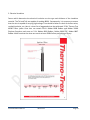
1
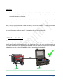
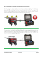
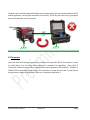
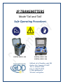
IP TRANSMITTERS Model TxII and TxIII Safe Operating Procedures 1800W-2400V-10A 3600W-2400V-10A 5000W-2400V-10A 860 boul. de la Chaudière, suite 200 Québec (Qc), Canada, G1X 4B7 Tel.: +1 (418) 877-4249 Fax: +1 (418) 877-4054 E-Mail: [email protected] Web site: www.gdd.ca Visit our web site at: WWW.GDD.CA To: Instrumentation GDD Inc. Discover GDD’s new products. Comment on or ask questions about products. 2013-12-11 Page 2 TABLE OF CONTENTS 1. INTRODUCTION............................................................................................................................ 4 2. GENERAL INFORMATION .............................................................................................................. 4 3. SAFETY - MATERIALS .................................................................................................................... 5 3.1 PERSONAL SAFETY EQUIPMENTS ................................................................................................................... 5 3.2 IP WIRES .................................................................................................................................................. 6 3.3 ELECTRODES.............................................................................................................................................. 6 3.4 GDD TRANSMITTER GROUND .................................................................................................................... 7 3.5 GENERATOR .............................................................................................................................................. 9 4. FIELD OPERATIONS..................................................................................................................... 10 4.1 WEATHER CONDITIONS ............................................................................................................................. 10 4.2 STAND-ALONE OPERATION......................................................................................................................... 10 ANNEX 1: WIRES SELECTION ............................................................................................................... 11 ANNEX 2: ELECTRODES ....................................................................................................................... 11 Instrumentation GDD Inc. 2013-12-11 Page 3 1. INTRODUCTION GDD IP Transmitters, models TxII and TxIII, are mostly used for time-domain induced polarization surveys. Since GDD IP Transmitters, models TxII and TxIII, are used to send currents into the ground using high voltage (up to 4800V in Master-Slave configuration), precautions have to be taken in order to minimize risks of electric shock or electrocution for the users. The main purpose of this document is to provide a quick overview on the best way to operate GDD IP transmitters safely. Take note that additional safety operating procedures may be necessary depending on the specific characteristics related to each survey and its location. IMPORTANT: Every geophysical field crew should read this document and the instruction manual provided with the equipment before using GDD IP Transmitters. 2. GENERAL INFORMATION This section presents some useful definitions or information related to electricity for a better understanding of the following safe operating procedure. VOLTAGE Voltage is a representation of the electric potential energy per unit charge. If a unit of electrical charge were placed in a location, the voltage indicates the potential energy of it at that point. In other words, it is a measurement of the energy contained within an electric field, or an electric circuit, at a given point. The common symbol for voltage is the uppercase letter V. The standard unit is the volt, symbolized by V. CURRENT Electrical current is a measure of the amount of electrical charge transferred per unit time. It represents the flow of electrons through conductive material. The common symbol for current is the uppercase letter I. The standard unit is the ampere, symbolized by A. Electric current can be Instrumentation GDD Inc. 2013-12-11 Page 4 either direct or alternating. Direct current (DC) flows in the same direction at all points in time, although the instantaneous magnitude of the current might vary. In an alternating current, the flow of charge carriers reverses the direction periodically. NOTE: GDD IP Transmitters are powered by alternative current (by standard commercial generators), but transmit direct current. The current and voltage represent a danger of electric shock or electrocution. For example, a voltage of 220V can generate a current higher than 3-4 mA that can be felt by humans. Moreover, if a current of 300mA / 400mA passes through your heart, you can have a heart attack and die. If you get an electric shock, you get a sudden painful feeling when you touch something which is connected to a supply of electricity. On the other hand, if someone is electrocuted, they are accidentally killed or badly injured when they touch something connected to a source of electricity. 3. SAFETY - MATERIALS This section presents a description of the proper materials that should be used with GDD IP Transmitters. 3.1 Personal Safety Equipments For the safety of the users, Instrumentation GDD inc. strongly recommends to always wear electrically insulated shoes and gloves when operating GDD IP Transmitters or working with a geophysical crew using this equipment. Instrumentation GDD Inc. 2013-12-11 Page 5 Wear electrically insulated shoes or boots. They should be approved by a Certifying organization (CSA, ANSI) i.e. marked with the logo . Wear electrically insulated gloves rated class 1 (7,5 kV). The operators should wear hearing protection if they work within 3 meters of the generator. 3.2 IP Wires When using GDD IP Transmitters, proper wire sizes with adequate electrical insulation must be used. It is the responsibility of the transmitter’s operator to make sure that the wires used with GDD IP Transmitters are adequate for the survey and are in good condition. The maximum voltage and current settings for a given survey must correspond to the current carrying capacity and the insulation material of the wires being used. With GDD IP Transmitters, you can send up to 10A or 4800V in the Master-Slave configuration. Consequently, it is necessary to make sure that the wires are appropriate to send a current of 10A or a voltage of 4800V. For example, we recommend using the following wires with GDD IP Transmitters: 18 AWG Insulated wires with a working voltage of 5000V. For more information, refer to Annex 1: Wires at the end of this document. 3.3 Electrodes For safety issues, please find below some recommendations for the electrodes used with GDD IP Transmitters in order to minimize risks of electric shock for the users. There is risk of electric shock each time an electrode is touched during a survey. Instrumentation GDD Inc. 2013-12-11 Page 6 Suggestions 1- The connection between the wire and the electrode should be insulated. With insulated connectors, it will be safer for the operator to connect or disconnect the wire from the electrode between each station. 2- An alarm could be added on the transmitter’s electrodes in order to warn the operator of the presence of a current. NOTE: The GDD team introduced a new IP accessory: the current indicator - in order to increase the safety of the field operators. For more information, refer to Annex 2 : Electrodes at the end of this document. 3.4 GDD Transmitter Ground GDD recommends to ground both the transmitter and the generator with an earth stake. The earth point (green jack in front of the Pelican case) on the GDD IP Transmitter, model TxII, is directly connected to the metal chassis of the transmitter. This is the only connection point to the chassis as the plastic case is electrically insulated from the chassis, making it safer to operate and reducing the risk of electrical hazards in case of internal electrical problems. Instrumentation GDD Inc. 2013-12-11 Page 7 Why is the earth wire in the power lead to the generator not connected? Generally, the green wire is typically connected to the metal chassis of the powered electrical unit to provide a grounding connection in case of an electrical malfunction. In order to be efficient though, the generator must be locally grounded with an earth stake. If not, the generator can be seen as an extension of the metal chassis of the transmitter, which could lead to electrical hazards in case of an electrical malfunction in the transmitter. The green wire is therefore not connected and the user must ground both the transmitter and the generator. If someone omits to do so, it is still safer to operate the TX than if the green wire were connected, the chassis of the transmitter being electrically insulated from the plastic case as well as the metal chassis of the generator. Instrumentation GDD Inc. 2013-12-11 Page 8 The green wire could also potentially add a ground loop through the earth stakes between the TX and the generator, causing false anomalies in the survey. This is why the earth wire in the power lead to the generator is not connected. 3.5 Generator You must make sure that your generator is suitable to be used with GDD IP Transmitters in order to avoid failure. You can check the transmitter’s nameplate for specificity. Every GDD IP Transmitter should be used with a regulated one phase generator (220-240VAC / 50-60Hz or 120VAC / 60 Hz depending on the model). It is important to make sure that the IP crew will use the generator properly as described in the user’s manual provided with it. Instrumentation GDD Inc. 2013-12-11 Page 9 4. FIELD OPERATIONS This section presents a description of the proper field operation that should be follow by the operators before, during and after a survey while using GDD IP Transmitters. 4.1 Weather Conditions For safety issues, Instrumentation GDD inc. does not recommend working when it is raining and/or during storms (presence of thunder and / or lightning). The presence of water on the ground, over the equipment, etc. increases the risk of accidental electric shocks since water is conductive. It is the responsibility of each operator in the field to suspend the survey when the weather conditions are not adequate (heavy rain, thunder, lightning, etc.). Lightning strikes will usually cause significant electrical interference to geophysical surveys and can damage the equipment. Moreover, they increase the risk of accidental electric shocks for the operators. In these kind of weather conditions, it is recommended to suspend the survey and disconnect the wires from the transmitter. The crew should go to a safe place until the storm is over and stay away from the wires that may have been struck by lightning. 4.2 Stand-alone operation Here are the basic steps for a safe stand-alone operation of GDD IP Transmitters : IMPORTANT: READ CAREFULLY Before manipulating the generator, wires or electrodes, it is VERY IMPORTANT for every operator to always make sure that the transmitter is turned off. On the other hand, the transmitter operator must always make sure that nobody has manipulated the electrodes, wires or generator before turning on the transmitter (IP crew or outsiders). Instrumentation GDD Inc. 2013-12-11 Page 10 1- Before using the generator, the following must be verified: The generator is securely parked and restrained on level ground. The engine has sufficient oil and coolant supply. The fuel supply is sufficient for the survey session. The generator is grounded with an earth stake. 2- Before turning the transmitter on, the following must be verified: The transmitter is properly connected to the generator. The chassis ground connector in front of the transmitter’s Pelican case is properly connected with an earth stake. The wires between the electrodes and the transmitter are in good condition. The wires are properly connected to the output terminals of the transmitter. In order to connect the wires to these terminals, the operator must press the button over each terminal and insert the wires. The operator should be careful; these terminals can reach up to 2400V. The wires are properly connected to the electrodes. There are two vent pipes on the control panel. Make sure that the airflow is not being obstructed by any object (e.g.: leaves, snow, etc.). The voltage selector is at the lowest voltage scale (150V). The 1.0X / 1.5X mode switch is at the 1.0X position. The contact with the ground is good. You can verify the contact with the ohmmeter display showing the ground resistance when the generator is plugged in and the transmitter is powered OFF. The transmitter’s operator must always confirm twice with every person in the crew that nobody has manipulated the electrodes, wires or generator before turning on the transmitter and that nobody is within 3 meters around these accessories (wires / electrodes / generator). 3- Turning on the equipment: Turn the generator ON. Turn the transmitter ON by toggling the ON/OFF Switch in high position (START). Increase the output voltage in order to increase the output power by pressing down the Voltage Selector and turning it clockwise at the same time. Instrumentation GDD Inc. 2013-12-11 Page 11 NOTES The transmitter will automatically stop within microseconds if a short circuit occurs or if the circuit becomes open. GDD IP Transmitters have an internal open loop protection circuit to prevent direct electric shock to the operator. This protection triggers when the electrodes are not connected to the output terminals or when the current is less than 30 mA. There is also an emergency stop button that shuts down all power inside the transmitter completely and quickly. This button is a safety mechanism and must be used in an emergency situation. The transmitter will automatically stop if you transmit more than the rated power. In this case, select a lower voltage scale. Turn the transmitter OFF and ON again to reset the STOP TX alarm. There is a built-in circuit breaker to protect the instrument from overloading. The fan inside the transmitter will automatically start to cool down the unit when the temperature inside the Pelican box is higher than 65°C. Moreover, it will automatically stop if the internal temperature is higher than 85°C inside the Pelican box. Leave the transmitter on until it cools off. 4- Turning off the equipment: Turn the transmitter OFF by toggling down (STOP) the On/Off switch before shutting down the generator. Shut down the generator. If you need to push down the emergency stop button (emergency situation), three (3) conditions must be met to reset the transmitter and make it work normally: The transmitter must be powered by an external supply. The emergency stop button must be pulled up. The power switch must be in STOP position (down). 5- Moving to the next station: The electrodes operator must confirm twice with the transmitter operator that the transmitter is turned OFF before approaching the electrode. Before touching the electrode, the operator disconnects the wire from the electrode and then, moves the electrode to the next station. Instrumentation GDD Inc. 2013-12-11 Page 12 After the electrode is set at its new position and reconnected to the wire, the operator must confirm twice with the transmitter’s operator that he is at least at 3 meters away from the electrode and wires. The transmitter’s operator is now ready to restart the procedure from the beginning (1Before using the generator,...) Instrumentation GDD Inc. 2013-12-11 Page 13 ANNEX 1: WIRE SELECTION 1- Current carrying capacity Factors which determine the current carrying capacity of wires are the cross-sectional area, the type of wire, the ambient temperature and the duty cycle used to transmit the waveform. With GDD IP Transmitters, you can send up to 10A. Consequently, it is necessary to make sure that the wires are appropriate to send a current of 10A. The following table lists the current carrying capacities for various wire sizes at different duty cycles. You must be careful not to exceed the current rating. Wire specifications This table is a guideline of ampacity or copper wire current carrying capacity following the Handbook of Electronic Tables and Formulas for American Wire Gauge. As you might guess, the rated ampacities are just a rule of thumb. In careful engineering, the insulation temperature limit, thickness, thermal conductivity and air convection, and temperature should all be taken into account. The current carrying capacity of the wire depends on the duty cycle. The applying formula is Icc = I √(1/Duty Cycle). For example, at a 50% duty cycle the wire will carry 41% more current 1.41 = √(1/0.5) and for a 25% duty cycle the wire can carry twice the current, 2 = √(1/0.25). Instrumentation GDD inc. suggests using stranded wires since they are more flexible and robust. Instrumentation GDD Inc. 2013-12-11 Page 14 2- Electrical insulation Factors which determine the electrical insulation are the type and thickness of the insulation material. The TxII and TxIII are capable of sending 4800V. Consequently, it is necessary to ensure that the wire is capable of carrying high voltage. Care should be taken to check for broken wires, cracked insulation, etc. Here is a short list of suggested wires that withstand 25 KV: Thermo-Trex 40200 Teflon jacket. Ones that can sustain 10 KV: Belden 8898 Rubber and Belden 39018 Ethylene-Propylene and some at 5 KV: Belden 8899 Rubber, Belden 9899 PVC, Belden 8897 Rubber. Make sure that the wires can sustain at least 5000V before performing a survey. Instrumentation GDD Inc. 2013-12-11 Page 15 Instrumentation GDD Inc. 2013-12-11 Page 16 Instrumentation GDD Inc. 2013-12-11 Page 17 ANNEX 2: ELECTRODES This annex presents some recommendations for the electrodes used with GDD IP Transmitters in order to minimize risk of being hurt by electric shock for the users . 1- Insulated electrodes Transmitter electrodes can be made from two different materials; a conductive one for the transmission of the current and an insulated material to protect the operator from high voltage (plastic, rubber, etc.). The handle or the top of the electrode could be isolated to protect the operator against electric shocks (current). 2- Safe connection The connection between the wire and the electrode could be insulated. With insulated connectors, it would be safer for the operator to connect or disconnect the wire from the electrode between each station. 3- Current Indicator Developed in 2010, the new GDD Current Indicator enhances field operator's safety during Resistivity and Induced Polarization surveys while they are manipulating wires and electrodes. A LED indicates the presence of current and the operator can follow the transmission cycle. Moreover, this is an innovative way to measure the real current transmitted into the ground. Instrumentation GDD Inc. 2013-12-11 Page 18