1
ULTRACASTER-2000
INSTALLATION AND OPERATION MANUAL
Please leave this manual with the unit
after installation
Important warranty information enclosed - see page 2.
Nel-Tech Labs, Inc.
101 Zachary Road
Manchester, NH 03109
ULTRACASTER-2000
1
Rev. 10/15/96
FCC Notice
WARNING: This equipment has been tested and found to comply with the limits for a Class A digital device pursuant to Part 15 of FCC
Rules. These limits are designed to provide reasonable protection against harmful interference when this equipment is operated in a
commercial environment. This equipment generates, uses, and can radiate radio frequency energy and, if not installed and used in
accordance with the instruction manual, may cause harmful interference to radio communications. Operation of this equipment in a
residential area is likely to cause harmful interference in which case the user will be required to correct the interference at his/her own
expense.
This digital apparatus does not exceed the Class A limits for radio noise emissions from digital apparatus set out in the Radio Interference
Regulations of the Canadian Department of Communications.
Le présent appareil numérique n'émet pas de bruits radioélectriques dépassant les limites applicables aux appareils numériques de la Class
A prescrites dans le Règlement sur le brouillage radioélectrique édicté par le ministère des Communications du Canada.
LIMITED WARRANTY
TERMS: Nel-Tech warrants to the original purchaser ("Buyer") that the Product sold is free from defects in material and workmanship at
the time of purchase. The warranty extends three (3) years from the date of original purchase and covers parts and labor. Buyer must
provide written notice to Nel-Tech within the warranty period of any defective part or conditions. If the defect is not the result of improper
use, service, maintenance or installation, and if the equipment has not been otherwise damaged or modified after shipment, Nel-Tech or
its authorized representative shall either replace or repair the defective Product at Nel-Tech's option. No credit shall be allowed for work
performed by Buyer or unauthorized parties. Out-of-warranty repairs will be invoiced at the current Nel-Tech hourly rate plus the cost of
parts, shipping and handling. IN THE EVENT THAT THE PRODUCT SERIAL NUMBER IS MISSING OR HAS BEEN TAMPERED
WITH IN ANY WAY, THE FOREGOING WARRANTY IS VOID AND WITHOUT EFFECT AND NEL-TECH SHALL HAVE NO LIABILITY
WHATSOEVER ON ACCOUNT OF DEFECTS TO SUCH PRODUCT.
LIMITATIONS: EXCEPT AS STATED ABOVE, THERE ARE NO WARRANTIES, EXPRESS OR IMPLIED, THAT EXTEND BEYOND
THE SPECIFICATIONS FOR THE PRODUCT. NEL-TECH EXPRESSLY DISCLAIMS ANY WARRANTY, EXPRESS OR IMPLIED,
THAT EQUIPMENT SOLD HEREUNDER IS OF MERCHANTIABLE QUALITY OR THAT IT CAN BE USED, OR IS FIT FOR ANY
PARTICULAR PURPOSE. BUYER PURCHASES AND ACCEPTS EQUIPMENT SOLELY ON THE BASIS OF THE WARRANTY
HEREINABOVE EXPRESSED. UNDER NO CIRCUMSTANCES SHALL NEL-TECH BE LIABLE BY VIRTUE OF THIS WARRANTY
OR OTHERWISE FOR ANY SPECIAL, INDIRECT, SECONDARY OR CONSEQUENTIAL DAMAGES TO ANY PERSON OR
PROPERTY ARISING OUT OF THE USE OR INABILITY TO USE THE PRODUCT.
REPAIRING OR REPLACING PRODUCT: Buyer may obtain the repair or replacement of any flawed part or equipment covered under
this warranty through Nel-Tech only. Buyer is responsible for all shipping and handling charges in connection with the performance of this
warranty. Products returned to Nel-Tech must be securely packaged to prevent damage in transit, freight prepaid, and insured for
replacement value. A return authorization number assigned by Nel-Tech must be clearly marked on the outside of the shipping container.
Proof of purchase must accompany shipment. Items delivered to Nel-Tech without a return authorization clearly marked on the outside
of the shipping container, and/or without proof of purchase will be refused. Please contact Nel-Tech at the address and phone number
below to receive a return authorization number and to arrange for the repair or replacement of a flawed part covered by this warranty.
Please indicate the Product's serial number in all correspondence; an authorization number will not be issued in the absence of a serial
number.
Nel-Tech Labs, Inc.
101 Zachary Road
Manchester, NH 03109-5609
Tel: (603) 641-8844
This manual Copyright 1993-1996 by Nel-Tech Labs, Inc. All rights reserved. No part of it may be copied, photocopied, reproduced,
translated, or reduced to any electronic medium or machine-readable form without Nel-Tech's prior written consent.
Information contained herein is subject to change without prior notification. Nel-Tech Labs, Inc. provides this manual without warranty of
any kind, expressed or implied. This user's manual may contain technical and/or typographical errors.
Printed in the U.S.A.
ULTRACASTER-2000
2
Rev. 10/15/96
1 Introduction
The UltraCaster is a Digital Audio Messaging System designed specifically for application in Point-of-Purchase
Merchandising. UltraCaster offers the performance, ease of operation, high reliability and quality of digital
storage and audio processing, combined with microprocessor technology to achieve truly natural sound
reproduction and user friendly features.
The UltraCaster offers a comprehensive set of features designed specifically for recording and timed-playback
of Point-of-Purchase advertisements. UltraCaster supports up to 32 messages with a total message time of over
64 minutes. Messages may be recorded from the embedded tape cassette player, a high quality telephone
handset or other external audio source. A built-in monitor speaker aids in verification and review of recorded
messages, and local monitoring of the audio output to the sound system including messages and background
music. Message playback can be automatically timed, externally driven or manually forced. Automatic message
timing ranges from continuous to 24 hours in 1-second timing increments, and messages may be individually
selected for automatic operation.
When used in conjunction with a background music source,the UltraCaster will gently fade the background music
to a user defined fade level while the message plays. After the message ends the background music is restored
to its user defined play level.
The UltraCaster provides the ultimate alternative to magnetic tape systems at an affordable price. Its simplicity
of use and greatly increased quality and reliability make most tape systems obsolete.
2 Features
! Up to 64 minutes of message time at 3.5 Khz
! User selectable message configurations
(1, 2, 4, 8 16 or 32 messages)
! User selectable audio bandwidths
(3.5, 3.5 Enhanced, 7.0 and 7.0 Enhanced)
! Embedded Tape Transport for automatic message loading
! Handset Aux Input for manual message loading
! Message Play Options
(Timed/Continuous/Trigger)
! Message Selection / Deselecting
! Liquid Crystal Display
ULTRACASTER-2000
3
Rev. 10/15/96
3 System Tour
3.1
System Display
The 4-line by 20-character LCD display is used to guide the user through the option menus.
3.2
Keyboard
The Keyboard is a 20-button keypad arranged in a 4 X 5 matrix. Keys are defined as follows:
Key
3.3
Definition
I
Function Key 1 - Context dependent key used in conjunction with line 4 of the LCD.
II
Function Key 2 - Context dependent key used in conjunction with line 4 of the LCD.
III
Function Key 3 - Context dependent key used in conjunction with line 4 of the LCD.
IV
Function Key 4 - Context dependent key used in conjunction with line 4 of the LCD.
0-9
Numeric Entry Keys
CLR
General Purpose Key which is used to exit or cancel selected functions
Front Panel Controls and Connectors
AUX AUDIO - This connector (3.5mm MONO Jack) provides input from an external audio source for loading
messages into the UltraCaster .
HANDSET - This connector (RJ-11) provides audio input from a special telephone handset for loading messages
directly into the UltraCaster. The recommended handset for this unit:
WALKER Equipment Corporation
Highway 151 South
Ringgold, Georgia 30736
Model W3-K-M
3.4
Rear Controls and Connectors
12 VDC - This connector (2.5mm DC Power Jack) provides power to the system from an external 12V DC @
1000 Ma source.
POWER ON/OFF - This switch enables power to the system.
LCD CONTRAST - Adjusts the contrast of the LCD display to compensate for lighting variations.
BGM IN - This connector (PHONO JACK) provides input from the BackGround Music (BGM) source.
AUDIO OUT - This connector (PHONO JACK) provides audio to the Music On-Hold or Sound System input.
ULTRACASTER-2000
4
Rev. 10/15/96
LEVEL HI/LO - This control selects the audio output impedance. Most applications require the switch to be set
in the "LO" position. In the "LO" position the unit can directly drive an 8 ohm speaker. The "HI" position is for
those cases where a line level output drive is needed.
TRIGGER - The connector (3.5mm MONO Jack) is used to initiate message play from an external source. A
momentary closure (Tip to Ring) with a switch or relay starts the next message in sequence to play if the system
has been programmed for "Trigger Play".
STOP - The connector (3.5mm MONO Jack) is used to stop message play from an external source. If no
message is playing, a closure on "STOP" prevents the message from playing until "STOP" is released. If a
message is playing, a closure on "STOP" cancels playing that message.
COMM CONTROL - The connector (9 pin D Female) is used to communicate with COMM port computerized
peripherals.
4 Getting Started
This section is intended as a quick start guide to using the UltraCaster. In this section you will be guided through
step-by-step system setup for configuring the UltraCaster for 4 messages at 3.5 Khz bandwidth, timed operation
at 30 second intervals. This quick start uses Nel-Tech's Sample Audio Cassette.
4.1
Fundamentals
The UltraCaster guides the user through configuring, programming, and loading messages via menu selections
presented on the SYSTEM DISPLAY. Certain display conventions have been set up to provide the user with
information of exactly where you are.
The top line of the display informs you of the current operation mode;
NTL UltraCaster Menu . . . . Top level menu
Configuration - Mode . . . . . Configuration Menu
Load Messages - Mode . . . Message Load Menu
Programming - Mode . . . . . System Programming
NTL UltraCaster 2000 System Running
Review Msgs - Mode . . . . . Message Review Mode
Diagnostic Tests . . . . Diagnostic
Line 2 generally offers the user additional menu selections available under the specific Mode. Menu selections
are always display within brackets;
"< menu item >"
Line 3 presents context-sensitive information pertaining to the specific operation being performed, while line 4
prompts the user for input based upon the available choices. For menu items, users enter either "Yes" or "No"
to each item. A "No" choice moves the user to the next menu item, while a "Yes" response either performs the
action or presents the user with more selections. Responses are entered by pressing the function key (I = Yes,IV
= No) associated with the text information displayed on the bottom line of the SYSTEM DISPLAY.
Keys "I", "II", "III" and "IV" are function keys whose action and meaning are constantly changing depending upon
the current operation. The meaning of these functions keys is determined by line 4 of the System Display. The
"CLR" key always cancels the current operation and returns the user to the main menu. In addition, a 15-second
timer is set each time the user enters a menu and is reset each time the user enters a key. If 15 seconds elapse
without user input, the system automatically reverts to the main menu.
ULTRACASTER-2000
5
Rev. 10/15/96
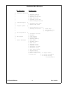
UltraCaster Menu Structure
Main Menu Items
+)
*
*
*
*
*
*
/)
*
*
/)
*
*
*
*
/)
*
*
/)
*
*
.)
Sub Menu Items
Configure System )),
Load Message(s)
Program System
Run Diagnostics
Run System
Review Messages
ULTRACASTER-2000
/)
/)
/)
/)
/)
.)
)),
/)
.)
)),
/)
.)
)),
/)
/)
/)
/)
/)
/)
/)
/)
/)
/)
/)
/)
/)
/)
/)
/Q
.Q
Message Tables
Fade Level Set
Message Level Set
BGM Level Set
Speaker Level Set
Auto Message Re-load
Automatic Msg Load
Manual Msg Load
Play Options )))))))),
Message Selection
/) Timed Play
/) Continuous Play
.) Trigger Play
Software Version
KeyPad
LCD Display
Data Memory
Message Memory
Aux Audio
Handset Audio
BGM Level
Message Level
Speaker Level
External Trigger
External Stop
Ext Power Sensor
Bypass Relay
Option Module )),
Real Time Clock /) 32 Input Module
Comm Port
/) 16 In/16 Out Module
.) 16 In/16 Out Dry
Closure Module
6
Rev. 10/15/96
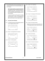
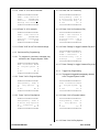
4.2
Configure System Example
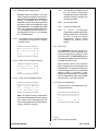
4.2.1 Turn on system Power, the SYSTEM DISPLAY
should appear as follows:
6444444444444444444447
5NTL UltraCaster Menu5
5< Configure System >5
5
5
5 Yes
No 5
9444444444444444444448
To automatically download the message memory from
a tape cassette containing the messages. Insert the
tape cassette into the tape drive located on the top of
the UltraCaster. Press "IV" (No) at the main menu
until the menu selection reads "Load Message(s)".
6444444444444444444447
5NTL UltraCaster Menu5
5< Load Message(s) >5
5
5
5 Yes
No 5
9444444444444444444448
4.2.2 Press "I" to configure the system
6444444444444444444447
5Configuration - Mode5
5< Message Tables >5
5
5
5 Yes
No 5
9444444444444444444448
4.3.1 Press "I" to load messages.
6444444444444444444447
5Load Messages - Mode5
5<Automatic Msg Load>5
5
5
5 Yes
No 5
9444444444444444444448
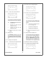
4.2.3 Press "I" to configure the message table
6444444444444444444447
5Config - Msg Tables 5
5#Msgs MsgSize BW Khz5
5 01
64(min) 3.5 5
5 Yes Prev Next Quit5
9444444444444444444448
4.3.2 Press "I" for automatic message load
6444444444444444444447
5Msg Load - Tape Auto5
5Loading Message = 015
5
(note 2)
Note: The number "64 (min)" represents the total
amount of Message Memory Equipped. This
number varies depending upon the amount of
message memory ordered: 8, 16, 32 or 64 minutes.
5Stop
Spkr5
9444444444444444444448
Note: Line 3 changes to reflect the current status of
the message load. The messages presented on line 3
are:
4.2.4 Press "III" for Next Table
6444444444444444444447
5Config - Msg Tables 5
5#Msgs MsgSize BW Khz5
5 02
32(min) 3.5 5
5 Yes Prev Next Quit5
9444444444444444444448
-- Rewinding Tape ->Tape is rewinding
-- Searching Tape ->Tape is playing and the system is looking for the
message audio
4.2.5 Press "III" for Next Table
6444444444444444444447
5Config - Msg Tables 5
5#Msgs MsgSize BW Khz5
5 04
16(min) 3.5 5
5 Yes Prev Next Quit5
9444444444444444444448
4.2.6 Press "I" for Yes to accept this Message Table
4.3
Load Messages Example
ULTRACASTER-2000
7
Rev. 10/15/96
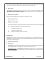
5
Once message audio is found, recording begins. Each
second of recorded audio is indicated by adding a dot
to the display.
After recording message 1, the system increments
the message number and begins searching for
message 2 on the tape. This process repeats for
all three messages on the sample tape. Once all
three messages are loaded, the system returns to
the main menu.
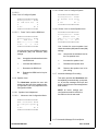
4.4.4 Press "I" for Timed Play
6444444444444444444447
5PGM - Time Interval 5
5Time
(HH:MM:SS)5
5Interval = 00:00:00 5
5Change
Quit5
9444444444444444444448
4.4.5 Press "I" to change the Time Interval
To hear the audio from the tape as it is being
recorded, press "IV" (Spkr). This key toggles the
internal speaker on and off. Note that when the
Spkr key is pressed, the dot display restarts.
4.4
Program System Example
4.4.1 To set the time interval for message play, advance
to the "Program System" mode.
4.4.6 Press "0" for 0 tens of hours
Note: This is one of the few occasions when Line
4 of the display does not refer to the function keys.
6444444444444444444447
5NTL UltraCaster Menu5
5< Program System >5
5
5
5 Yes
No 5
9444444444444444444448
6444444444444444444447
5PGM - Time Interval 5
5Time
(HH:MM:SS)5
5Interval = 00:00:00 5
5Change Time Interval5
9444444444444444444448
4.4.2 Press "I" to Program the Time Interval
6444444444444444444447
5Programming - Mode 5
5<
Play Options
>5
5
5
5 Yes
No 5
9444444444444444444448
4.4.7 Press "0" for 0 hours
6444444444444444444447
5PGM - Time Interval 5
5Time
(HH:MM:SS)5
5Interval = 00:00:00 5
5Change Time Interval5
9444444444444444444448
4.4.3 Press "I" for Play Options
6444444444444444444447
5Programming - Mode 5
5 Select Play Option 5
5<
Timed Play
>5
5 Yes
No 5
9444444444444444444448
ULTRACASTER-2000
6444444444444444444447
5PGM - Time Interval 5
5Time
(HH:MM:SS)5
5Interval = 00:00:00 5
5Change Time Interval5
9444444444444444444448
4.4.8 Press "0" for 0 tens of minutes
6444444444444444444447
5PGM - Time Interval 5
5Time
(HH:MM:SS)5
5Interval = 00:00:00 5
5Change Time Interval5
9444444444444444444448
8
Rev. 10/15/96
4.4.9 Press "0" for 0 minutes
4.5.2 Press "I" to Run
6444444444444444444447
5PGM - Time Interval 5
5Time
(HH:MM:SS)5
5Interval = 00:00:30 5
5Change Time Interval5
9444444444444444444448
Message Interval Time Display
6444444444444444444447
5NTL UltraCaster 20005
5 Next Message = 01 5
5Next Play = 00:00:305
5Play Vol Spkr Quit5
9444444444444444444448
4.4.10 Press "3" for 30 seconds
4.5.3 The Next Play time counts down until 00:00:00
and then the display changes.
6444444444444444444447
5PGM - Time Interval 5
5Time
(HH:MM:SS)5
5Interval = 00:00:30 5
5Change Time Interval5
9444444444444444444448
Message Playing Display
6444444444444444444447
5NTL UltraCaster 20005
5 Timed Message Play 5
5Playing Message = 015
5Stop Vol Spkr Quit5
9444444444444444444448
4.4.11 Press "0" to complete the 30 seconds
6444444444444444444447
5PGM - Time Interval 5
5Time
(HH:MM:SS)5
5Interval = 00:00:30 5
5Change
Quit5
9444444444444444444448
Play -
Provides the user the ability to
manually initiate the playing of a
message.
Vol -
Provides the user with the ability to adjust
the audio level of the message.
Spkr -
Toggles the internal speaker
On and Off.
Quit -
Stops message play and
escapes from the Run Mode.
Stop -
Stops message play and resets
to the next selected message
and restarts the interval timer.
4.4.12 Press "CLR" to exit Time Interval change
4.5
Run System Example
4.5.1 To Run the System, advance to the "Run System"
mode.
6444444444444444444447
5NTL UltraCaster Menu5
5<
Run System
>5
5
5
5 Yes
No 5
9444444444444444444448
ULTRACASTER-2000
9
Rev. 10/15/96
5 Installation
5.1
Site Requirements:
The UltraCaster can be installed in any normal office environment within 6 feet of a 110 VAC outlet. The product
is designed for mounting on a "tabletop" or shelf unit. Care should be taken to allow access to the rear connections,
tape deck and front panel controls.
5.2
Connections:
5.2.1 Audio Output - Connect the AUDIO OUT jack on the UltraCaster to the Music On-Hold jack of the telephone system
or the Audio Input Jack of the Sound System.
5.2.2 LEVEL HI/LO - Depending upon the input impedance requirement of the telephone or sound system, set this switch
to either the "LO" 8 ohm, or "HI" 1000 ohm position.
5.2.3 BGM IN - Connect the BGM IN jack on the UltraCaster to the output of the external music source.
5.2.4 TRIGGER - For "Trigger Play", connect a 3.5mm Male MONO Plug into the "TRIGGER" jack. Activation can be a
relay closure or switch located within 1000 wire feet of the UltraCaster. The "TRIGGER" input is optically isolated
for noise and transient protection.
5.2.5 STOP - The "STOP" input is used to HOLDOFF or Stop message play. The use the "STOP" input, connect a 3.5mm
Male MONO Plug into the "STOP" jack. Activation can be a relay closure or switch located within 1000 wire feet of
the UltraCaster. The "STOP" input is optically isolated for noise and transient protection.
5.2.6 COMM PORT - Factory option used to communicate with Sign Displays and other computerized peripherials.
5.3
Option Modules
5.3.1 Input Module - The Input Module adds the capability to play any of the 32 messages from external contact closures
and provides a BUSY relay which is activated during message play. With external operation, messages can be
played by contact closures such as push buttons, door switches, alarm systems, etc. Each message may be
accessed externally via an optically isolated input. Distances of 1500 cable feet can be supported directly off the
Input Module without external isolation of protection devices required. Connection to the Input Module is via a 50-pin
CHAMP-type connector;
AMPHENOL # 57-10500-7 or equivalent
See Appendix A for wiring connection information.
5.3.2 I/O Module - The I/O Module adds the capability to play any of the first 16 messages from external contact closures
and provides a BUSY relay closure associated with each of the first 16 messages, which is activated during message
play. With external operation, messages can be played by contact closures such as push buttons, door switches,
alarm systems, etc. Each message may be accessed externally via an optically isolated input. Distances of 1500
cable feet can be
ULTRACASTER-2000
10
Rev. 10/15/96
supported directly off the I/O Module without external isolation of protection devices required. Connection to the I/O
Module is via a 50-pin CHAMP-type connector;
AMPHENOL # 57-10500-7 or equivalent
See Appendix B for wiring connection information.
5.3.3 I/O 16B Module - Same as I/O Module except that the external contact closures are dry (isolated) closures.
See Appendix C for wiring connection information.
ULTRACASTER-2000
11
Rev. 10/15/96
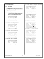
6 Program System
6.1
6.1.1.4 Press "Change" to change the Time Interval
Play Options
The UltraCaster base system provides the user with
four options for playing messages: Timed, Continuous,
Trigger, External and Manual.
6444444444444444444447
5PGM - Time Interval 5
5Time
(HH:MM:SS)5
5Interval = 00:00:00 5
5Change Time Interval5
9444444444444444444448
6.1.1 Timed Play Programming
6.1.1.5 Press "0 - 2" for tens of hours
To program the time interval for message play,
advance to the "Program System" mode.
6444444444444444444447
5NTL UltraCaster Menu5
5< Program System >5
5
5
5 Yes
No 5
9444444444444444444448
6.1.1.6 Press "0 - 9" for hours
6444444444444444444447
5PGM - Time Interval 5
5Time
(HH:MM:SS)5
5Interval = 00:00:00 5
5Change Time Interval5
9444444444444444444448
6.1.1.1 Press "Yes" to Program System
6444444444444444444447
5Programming - Mode 5
5<
Play Options
>5
5
5
5 Yes
No 5
9444444444444444444448
6.1.1.7 Press "0 - 5" for tens of minutes
6444444444444444444447
5PGM - Time Interval 5
5Time
(HH:MM:SS)5
5Interval = 00:00:00 5
5Change Time Interval5
9444444444444444444448
6.1.1.2 Press "Yes" for Play Options
6444444444444444444447
5Programming - Mode 5
5 Select Play Option 5
5<
Timed Play
>5
5 Yes
No 5
9444444444444444444448
6.1.1.8 Press "0 - 9" for minutes
6444444444444444444447
5PGM - Time Interval 5
5Time
(HH:MM:SS)5
5Interval = 00:00:00 5
5Change Time Interval5
9444444444444444444448
6.1.1.3 Press "Yes" for Timed Play
6444444444444444444447
5PGM - Time Interval 5
5Time
(HH:MM:SS)5
5Interval = 00:00:00 5
5Change
Quit5
9444444444444444444448
ULTRACASTER-2000
6444444444444444444447
5PGM - Time Interval 5
5Time
(HH:MM:SS)5
5Interval = 00:00:00 5
5Change Time Interval5
9444444444444444444448
12
Rev. 10/15/96
6.1.1.9 Press "0 - 5" for tens of seconds
6.1.2.4 Press "No" for Timed Play
6444444444444444444447
5PGM - Time Interval 5
5Time
(HH:MM:SS)5
5Interval = 00:00:00 5
5Change Time Interval5
9444444444444444444448
6444444444444444444447
5Programming - Mode 5
5 Select Play Option 5
5< Continuous Play >5
5 Yes
No 5
9444444444444444444448
6.1.1.10 Press "0 - 9" for seconds
6.1.2.5 Press "Yes" for Continuous Play
6444444444444444444447
5PGM - Time Interval 5
5Time
(HH:MM:SS)5
5Interval = 00:00:00 5
5Change
Quit5
9444444444444444444448
6444444444444444444447
5PGM - Time Interval 5
5PGM - Continuous
5
5Constant Play = Off 5
5Change
Quit5
9444444444444444444448
6.1.1.11 Press "CLR" to exit Time Interval change
6.1.2.6 Press "Change" to toggle Constant Play to On
6444444444444444444447
5PGM - Time Interval 5
5PGM - Continuous
5
5Constant Play = On 5
5Change
Quit5
9444444444444444444448
6.1.2 Continuous Play Programming
6.1.2.1 To program for continuous message play,
advance to the "Program System" mode.
6444444444444444444447
5NTL UltraCaster Menu5
5< Program System >5
5
5
5 Yes
No 5
9444444444444444444448
6.1.2.7 Press "Change" to toggle Constant Play to Off
6.1.3
Trigger Play Programming
6.1.3.1 To program for triggered message play, advance
to the "Program System" mode.
6.1.2.2 Press "Yes" to Program System
6444444444444444444447
5Programming - Mode 5
5<
Play Options
>5
5
5
5 Yes
No 5
9444444444444444444448
6444444444444444444447
5NTL UltraCaster Menu5
5< Program System >5
5
5
5 Yes
No 5
9444444444444444444448
6.1.2.3 Press "Yes" for Play Options
6.1.3.2 Press "Yes" to Program System
6444444444444444444447
5Programming - Mode 5
5 Select Play Option 5
5<
Timed Play
>5
5 Yes
No 5
9444444444444444444448
6444444444444444444447
5Programming - Mode 5
5<
Play Options
>5
5
5
5 Yes
No 5
9444444444444444444448
6.1.3.3 Press "Yes" for Play Options
ULTRACASTER-2000
13
Rev. 10/15/96
6.2 Message Selection Programming
6444444444444444444447
5Programming - Mode 5
5 Select Play Option 5
5<
Timed Play
>5
5 Yes
No 5
9444444444444444444448
For messages to be played by Timed, Continuous or
Trigger options, they must first be selected. This
feature allows for the addition or removal of existing
messages from the play list. Messages loaded from
the internal tape drive are automatically selected for
play and must be manually de-selected, while
messages manually loaded must be manually
selected.
6.1.3.4 Press "No" for Timed Play
6444444444444444444447
5Programming - Mode 5
5 Select Play Option 5
5< Continuous Play >5
5 Yes
No 5
9444444444444444444448
To select or de-select a message, advance to
"Program System". Upon entering the "Programming
- Mode" advance to "Message Selection" and press
"yes". The following screen is displayed:
6444444444444444444447
5Program - Msg Select5
5Msg # = 01 02 03 045
5Active = Y Y Y Y5
5Change <-> Done5
9444444444444444444448
6.1.3.5 Press "No" for Continuous Play
6444444444444444444447
5Programming - Mode 5
5 Select Play Option 5
5<
Trigger Play
>5
5 Yes
No 5
9444444444444444444448
Line 3 indicates whether the message is currently
selected.
6.1.3.6 Press "Yes" for Trigger Play
Y = Selected, N = Not Selected
6444444444444444444447
5PGM - Time Interval 5
5PGM - Trigger
5
5Triggered Play = Off5
5Change
Quit5
9444444444444444444448
Change -
6.1.3.7 Press "Change" to toggle Triggered Play to On
6444444444444444444447
5PGM - Time Interval 5
5PGM - Trigger
5
5Triggered Play = On 5
5Change
Quit5
9444444444444444444448
toggles the message closest to the
"=" between selected and not
selected
<-
- Decrements the number of the message
closest to the "="
->
- Increments the number of the message
closest to the "="
Done - Completes the message selection process
6.1.3.8 Press "Change" to toggle Triggered Play to Off
ULTRACASTER-2000
14
Rev. 10/15/96
7 Run System
7.1
Timed Message Play
Under Timed Operation, UltraCaster plays selected messages upon expiration of the time interval. One message plays
per expiration of the time interval. Messages are played in sequential order from the lowest selected message to the
highest. During Timed Operation, the next message to be played is shown on the SYSTEM DISPLAY. Upon expiration
of the time interval, the BGM is faded to the preset level, and the message begins to play. Once the message has
finished playing, the BGM is restored and the next message number, and time interval until the next message play is
displayed.
During Timed Operation, manual message play (Play), message volume adjustment (Vol) and Speaker (Spkr) On/Off are
enabled. Halt Timed Operation, the user must press the "Quit" or "CLR" switches. Pressing the "Stop" key will stop the
current message and reset the timer for the next message.
7.2
Continuous Play
For Continuous Play, selected messages are played one after the other without any time between messages. Messages
are played in sequential order from the lowest selected message to the highest selected message back again to the
lowest. Unlike Timed Operation, Continuous Play does not restore the BGM between messages.
During Continuous Play, Manual, Timed and Trigger message play is disabled. Message volume adjustment (Vol) and
Speaker (Spkr) On/Off is enabled. Halt Continuous Operation, the user must press the "Quit" or "CLR" switches.
Pressing the "Stop" key will stop the current message and reset the timer for the next message.
7.3
Triggered Play
For Triggered Play, selected messages are played after a momentary closure of the "TRIGGER". Messages are played
in sequential order from the lowest selected message to the highest selected message back again to the lowest. Like
Timed Operation, Trigger Play restores the BGM between messages.
During Trigger Play, manual message play (Play), message volume adjustment (Vol) and Speaker (Spkr) On/Off are
enabled. To halt Trigger Play, the user must press the "Quit" or "CLR" switches.
7.4
Manual Play
Manual Play provides a means for the user to play a message immediately. Under Manual Play, messages need not be
selected. To Manual Play a message, the user presses the "PLAY" switch, enters the message number and then presses
"START". The BGM is faded to the preset level, and the message begins to play. Once the message is finished playing,
the BGM is restored and the system returns to normal operation.
7.5
External Message Play (Option Module)
External Message Play provides a means for the user to play any loaded message from an external contact closure. For
External Play, messages need not be selected. To play a message from an external source requires a contact closure
to be applied to the appropriate signal lead of the Input Module or Input/Output Module or I/O 16B Module. Each contact
closure is remembered and the associated message is inserted into the message play list. A momentary closure (250
Msec) causes the associated message to be inserted into the play list. After the message is played, it is removed from
the play list. Should the closure occur again or if the closure is held, the message is again inserted into the play list.
Messages are played by first examining the programmed message play operation (Timed, Triggered), then examining
the play list for contact closure messages. Contact closure messages are played on a "round robin" basis, starting at the
ULTRACASTER-2000
15
Rev. 10/15/96
lowest numbered message to the highest and back. Should a message have a constant contact closure, it will be played
once; all other contact closure messages will be played prior to play that message again.
7.6
Speaker On/Off
The UltraCaster has an internal speaker for the convenience of the user in listening to both messages and the
background music while in "Run Mode." The level of the audio at the speaker is set in the "Configuration Mode." The
"Spkr" switch turns the internal speaker On and Off.
7.7
Message Volume Adjustment
Message volume is adjustable during "Run Mode" by pressing the "Vol" switch.
6444444444444444444447
5NTL UltraCaster 20005
5
Message Level
5
5MX------|---------MN5
5 Yes
<->
No 5
9444444444444444444448
Line 3 shows the current level of the message relative to maximum (MX) volume and minimum (MN) volume.
Yes - Accepts the the indicated level as the new message volume
<-
- Increases the message volume
->
- Decreases the message volume
No
- Restores the message volume to its prior setting
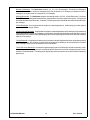
8 Configuration
UltraCaster may be configured by the user to better meet their application needs. Configuration options include:
Message Memory Capacity (factory option), Number of Messages, Message Bandwidth, BGM Fade Level, Message
Level, BGM Level and Speaker Level.
8.1
Configuring The UltraCaster
8.1.1 Message Tables
The UltraCaster uses pre-defined Message Tables to simplify the selection of Number of Messages, Message Size
and MessageBandwidth. The message Table is structured in the following manner:
Message Memory Capacity - The UltraCaster supports message memory capacities of 8, 16, 32 and 64 minutes
of audio information at the standard 3.5 Khz bandwidth. The amount of message memory is equipped at the factory
and is not field-upgradable.
ULTRACASTER-2000
16
Rev. 10/15/96
Number of Messages - The UltraCaster supports 1, 2, 4, 8, 16 or 32 messages. The Number of Messages
represents the maximum number of messages which may be loaded. If, for example, you wanted to load 13
messages, the system must be configured for 16 messages.
Message Bandwidth - The UltraCaster supports 4 bandwidth options; 3.5 Khz, 3.5 Khz Enhanced, 7.0 Khz and
7.0 Khz Enhanced. Message bandwidth is directly representative of the audio quality of the system. The higher the
bandwidth the better the audio quality. In addition, increasing the system bandwidth decreases the available time
per message.
3.5 Khz Bandwidth - is most appropriate for telephone-oriented applications. At this setting, the audio signal is
digitized at 35,000 bits per second.
3.5 Khz Enhanced Bandwidth - is appropriate for telephone-oriented applications and for store point-of-purchase and
exhibits applications of speech-only messages. At this setting, the audio signal is digitized at 46,000 bits per second
representing a 30% increase in the digital sampling rate and a corresponding 30% decrease in total audio message
capacity of the system.
7.0 Khz Bandwidth - is appropriate for store point-of-purchase and exhibit applications where messages are played
over a sound system. At this setting, the audio signal is sampled at 70,000 bits per second yielding 1/2 of the total
audio message capacity over the standard 3.5 Khz bandwidth.
7.0 Khz Enhanced Bandwidth - increases the digital sampling rate to 92,000 bits per second representing a 30%
increase in the digital sampling rate and a corresponding 30% decrease in total audio message capacity over the
standard 7.0 Khz bandwidth. The setting yields high quality audio reproduction for sensitive audio broadcasting
applications.
ULTRACASTER-2000
17
Rev. 10/15/96
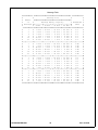
Message Table
64444444444;444444444444444444444444444444444444444;444444444447
5
5
Message Size
5
5
5 Number :444444444444444444444444444444444444444<
5
5
of
5
Message Memory Capacity
5 Bandwidth 5
5 Messages K)))))))))0)))))))))0)))))))))0)))))))))M
(Khz)
5
5
5 8 Min * 16 Min * 32 Min * 64 Min 5
5
:4444444444>444444444P444444444P444444444P444444444>44444444444<
5
1
5
8 min * 16 min * 32 min * 64 min 5
3.5
5
5
2
5
4 min * 8 min * 16 min * 32 min 5
3.5
5
5
4
5
2 min * 4 min * 8 min * 16 min 5
3.5
5
5
8
5
1 min * 2 min * 4 min * 8 min 5
3.5
5
5
16
5 30 sec * 1 min * 2 min * 4 min 5
3.5
5
5
32
5 15 sec * 30 sec * 1 min * 2 min 5
3.5
5
K))))))))))O)))))))))3)))))))))3)))))))))3)))))))))O)))))))))))M
5
1
5
6 min * 12 min * 24 min * 48 min 5
3.5E
5
5
2
5
3 min * 6 min * 12 min * 24 min 5
3.5E
5
5
4
5 90 sec * 3 min * 6 min * 12 min 5
3.5E
5
5
8
5 45 sec * 90 sec * 3 min * 6 min 5
3.5E
5
5
16
5 22 sec * 45 sec * 90 sec * 3 min 5
3.5E
5
5
32
5 11 sec * 22 sec * 45 sec * 90 sec 5
3.5E
5
K))))))))))O)))))))))3)))))))))3)))))))))3)))))))))O)))))))))))M
5
1
5
4 min * 8 min * 16 min * 32 min 5
7.0
5
5
2
5
2 min * 4 min * 8 min * 16 min 5
7.0
5
5
4
5
1 min * 2 min * 4 min * 8 min 5
7.0
5
5
8
5 30 sec * 1 min * 2 min * 4 min 5
7.0
5
5
16
5 15 sec * 30 sec * 1 min * 2 min 5
7.0
5
5
32
5
7 sec * 15 sec * 30 sec * 1 min 5
7.0
5
K))))))))))O)))))))))3)))))))))3)))))))))3)))))))))O)))))))))))M
5
1
5
3 min * 6 min * 12 min * 24 min 5
7.0E
5
5
2
5 90 sec * 3 min * 6 min * 12 min 5
7.0E
5
5
4
5 45 sec * 90 sec * 3 min * 6 min 5
7.0E
5
5
8
5 22 sec * 45 sec * 90 sec * 3 min 5
7.0E
5
5
16
5 11 sec * 22 sec * 45 sec * 90 sec 5
7.0E
5
5
32
5
5 sec * 11 sec * 22 sec * 45 sec 5
7.0E
5
94444444444=444444444N444444444N444444444N444444444=444444444448
ULTRACASTER-2000
18
Rev. 10/15/96
8.1.2 Message Table Programming
Yes -
Message Tables are present in the order
listed on the previous page. Entering "Next"
steps down the message table, increasing the
number of messages and the system
bandwidth. Entering "Prev" steps up the table
with lower number of messages at a lower
system bandwidth. The message table starts
with 1 - 32 messages at 3.5 Khz, advances to
1 - 32 messages at 3.5 Khz Enhanced, to 1 32 messages at 7.0 Khz, to 1 - 32 messages
at 7.0 Khz Enhanced
To accept the current table entry as
the new system configuration.
Changing the system configuration
erases all existing messages and
message selections.
Next - For next table entry
Prev - For previous table entry
Quit - T o
cancel
the Message
Configuration update and restore the
existing configuration. Quit allows
the user to scan the various
configuration options without
modifying the system's current
setting.
8.1.2.1 To program the for a specific message
configuration, advance to the "Configure
System" mode.
6444444444444444444447
5NTL UltraCaster Menu5
5< Configure System >5
5
5
5 Yes
No 5
9444444444444444444448
8.1.3 Fade Level
The UltraCaster may be configured to
reduce the level of the background music
during message play by setting the Fade
Level parameter. The UltraCaster provides
the user with complete control over the level
of background music level.
8.1.2.2 Press "Yes" to Configure System
6444444444444444444447
5Configuration - Mode5
5< Message Tables >5
5
5
5 Yes
No 5
9444444444444444444448
When the Fade Level is set to maximum
(MX), no background music is heard during
message play. For applications where the
stored message is voice only, a partial fade
adds the effect of providing a music
background during the play of a message,
while for applications where the message
contains music, a full fade is desired.
8.1.2.3 Press "Yes" for Message Tables
6444444444444444444447
5Config - Msg Tables 5
5#Msgs MsgSize BW Khz5
5 01
64(min) 3.5 5
5 Yes Prev Next Quit5
9444444444444444444448
8.1.3.1 Fade Level Adjustment
The Fade Level is only adjustable in the
Configuration Mode.
6444444444444444444447
5NTL UltraCaster Menu5
5< Configure System >5
5
5
5 Yes
No 5
9444444444444444444448
Note: The number "64(min)" represents the
total amount of Message Memory Equipped.
This number varies depending upon the
amount of message memory ordered; 8(min),
16(min), 32(min) or 64 (min).
8.1.3.1.1
Press "Yes" to Configure System
ULTRACASTER-2000
19
Rev. 10/15/96
8.1.4.1.2 Press "Yes" to Configure System
6444444444444444444447
5Configuration - Mode5
5< Fade Level Set >5
5
5
5 Yes
No 5
9444444444444444444448
8.1.3.1.2
6444444444444444444447
5Configuration - Mode5
5< Message Level Set>5
5
5
5 Yes
No 5
9444444444444444444448
Press "Yes" to set the fade level
8.1.4.1.3 Press "Yes" to set the message level
6444444444444444444447
5Configuration - Mode5
5
BGM Fade Level
5
5MN------|---------MX5
5 Yes
<->
No 5
9444444444444444444448
6444444444444444444447
5Configuration - Mode5
5
Message Level
5
5MX------|---------MN5
5 Yes
<->
No 5
9444444444444444444448
Line 3 shows the current fade level relative to
maximum (MX) fade and minimum (MN) fade.
Yes -
Accepts the the indicated level as the
new fade level
<-
Decreases the fade level (more
background music)
->
Increases the fade level (less
background music)
Line 3 shows the current message level
relative to maximum (MX) and minimum (MN)
settings.
No - Restores the fade level to its prior
setting
<-
Increases the message level
->
Decreases the message level
8.1.5 Background Music (BGM) Level
The UltraCaster provides the user with
control over the level of the message audio.
The message level may be set as both a
configuration parameter and during message
play.
The recommended method for adjusting the
level of the BackGround Music (BGM) is to
adjust the level at the BGM source.
However, the UltraCaster does provide the
user with control over the level of the
background music audio. The BGM Level is
only adjustable in the Configuration Mode.
8.1.4.1 Message Level Adjustment
Advance the the Configuration Mode.
8.1.5.1 BackGround Music Level Adjustment
6444444444444444444447
5NTL UltraCaster Menu5
5< Configure System >5
5
5
5 Yes
No 5
9444444444444444444448
ULTRACASTER-2000
Accepts the the indicated level as
the new message level
No - Restores the message level to its prior
setting
8.1.4 Message Level
8.1.4.1.1
Yes -
8.1.5.1.1 Advance the the Configuration Mode.
6444444444444444444447
5NTL UltraCaster Menu5
5< Configure System >5
5
5
5 Yes
No 5
9444444444444444444448
20
Rev. 10/15/96
8.1.6.1.2 Press "Yes" to Configure System
8.1.5.1.2
Press "Yes" to Configure System
6444444444444444444447
5Configuration - Mode5
5< Speaker Level Set>5
5
5
5 Yes
No 5
9444444444444444444448
6444444444444444444447
5Configuration - Mode5
5< BGM Level Set
>5
5
5
5 Yes
No 5
9444444444444444444448
8.1.5.1.3
8.1.6.1.3 Press "Yes" to set the Speaker level
6444444444444444444447
5Configuration - Mode5
5
Speaker Level
5
5MX------|---------MN5
5 Yes
<->
No 5
9444444444444444444448
Press "Yes" to set the BGM level
6444444444444444444447
5Configuration - Mode5
5
BGM Level
5
5MX------|---------MN5
5 Yes
<->
No 5
9444444444444444444448
Line 3 shows the current speaker level
relative to maximum (MX) and minimum (MN)
settings.
Line 3 shows the current BGM level relative
to maximum (MX) and minimum (MN)
settings.
Yes -
Accepts the the indicated level as
the new speaker level
Yes - Accepts the the indicated level as the
new BGM level
<-
Increases the speaker level
<-
- Increases the BGM level
->
Decreases the speaker level
->
- Decreases the BGM level
No -
Restores the speaker level to its
prior setting
No - Restores the BGM level to its prior
setting
8.1.7 Automatic Message Re-Loading
8.1.6 Speaker Level
This option provides the UltraCaster with
the capability to automatically, upon power
on, to load the messages from tape and
begin "running" as soon as messages have
been loaded.
The UltraCaster provides the user with
control over the level of the speaker audio.
The Speaker Level is only adjustable in the
Configuration Mode.
NOTE: all levels, settings and
configurations remain in effect from
the last time the unit was used.
8.1.6.1 Speaker Level Adjustment
8.1.6.1.1
Advance to the Configuration Mode.
6444444444444444444447
5NTL UltraCaster Menu5
5< Configure System >5
5
5
5 Yes
No 5
9444444444444444444448
8.1.7.1 Automatic Message Re-Load Option
ULTRACASTER-2000
21
Rev. 10/15/96
8.1.7.1.1
Loading the UltraCaster from a tape cassette is
as simple as inserting the tape cassette into the
tape transport located on the top of the
UltraCaster and closing the door.
Advance to the Configuration Mode.
6444444444444444444447
5NTL UltraCaster Menu5
5< Auto Msg Re-Load >5
5
5
5 Yes
No 5
9444444444444444444448
8.1.7.1.2
Note: If the Automatic Message Re-Loading
option is enabled, the system will, upon
power up, automatically load the tape
messages and begin operation without user
input. Automatic Message Re-Loading only
works upon power up.
Press "Yes" to Access Re-Load Option
9.1.1 Advance to the Load Messages Mode.
6444444444444444444447
5Configuration - Mode5
5Auto Message Re-Load5
5 Auto Re-Load = Off 5
5 Change
Quit5
9444444444444444444448
8.1.7.1.3
6444444444444444444447
5NTL UltraCaster Menu5
5< Load Message(s) >5
5
5
5 Yes
No 5
9444444444444444444448
Press "Change" to enable or disable
re-load option
9.1.2 Press "Yes" to Load Messages
6444444444444444444447
5Configuration - Mode5
5Auto Message Re-Load5
5 Auto Re-Load = On 5
5 Change
Quit5
9444444444444444444448
6444444444444444444447
5Load Messages - Mode5
5<Automatic Msg Load>5
5
5
5 Yes
No 5
9444444444444444444448
9.1.3 Press "Yes" for automatic message load
9 Message Loading
6444444444444444444447
5Msg Load - Tape Auto5
5Loading Message = 015
5
(note 2)
5
5Stop
Spkr5
9444444444444444444448
The UltraCaster allows for messages to be
loaded automatically through the internal tape
deck or manually with an external handset or
other external audio source.
9.1
Automatic Message Loading
Note: Line 3 changes to reflect the current
status of the message load. The messages
presented on line 3 are:
Automatic message loading simplifies the process
of loading messages into the UltraCaster. When
selected, automatic message loading rewinds the
tape and begins searching for the first message.
Messages contained on the tape are loaded in
order, starting at one and advancing to either the
last message on the tape, or the last configured
message in the system. Messages that are
automatically loaded are also automatically
selected for play.
ULTRACASTER-2000
-- Rewinding Tape ->Tape is rewinding
-- Searching Tape ->Tape is playing and the system is
looking for the message audio
22
Rev. 10/15/96
6444444444444444444447
5Msg Load - Manual
5
5Enter Message # = 005
5- Select Message -5
5
5
9444444444444444444448
>Once message audio is found, recording begins.
Each second of recorded audio is indicated by
adding a dot to the display.
Stop
>Stop message loading. Any messages which
have completed loading prior to pressing "Stop"
exist in message memory.
9.2.4 Enter the number of the message to be
loaded. Note that message numbers require
two digits (01, 02...).
Spkr
>Toggle internal speaker On/Off for listening to
messages as they are being loaded.
9.2.5 If the message already exists, then the
following screen is displayed.
After recording message 1, the system
increments the message number and begins
searching for message 2 on the tape, etc.
Once all the messages are loaded, the
system returns to the main menu.
9.2
6444444444444444444447
5Msg Load - Manual
5
5Enter Message # = 015
5 Re-Record Message? 5
5 Yes
No 5
9444444444444444444448
Manual Message Loading
Yes
- Erases current message and
allows the user to re-record the
message.
No
- Cancel message record
UltraCaster allows for manually loading
messages from two types of external audio input
sources, Handset or Aux Input.
9.2.1 Advance to the Load Messages Mode.
9.2.6
6444444444444444444447
5NTL UltraCaster Menu5
5< Load Message(s) >5
5
5
5 Yes
No 5
9444444444444444444448
6444444444444444444447
5Msg Load - Manual
5
5Enter Message # = 015
5
5
5 Rec
Spkr Quit5
9444444444444444444448
9.2.2 Press "Yes" to Load Messages
6444444444444444444447
5Load Messages - Mode5
5< Manual Msg Load >5
5
5
5 Yes
No 5
9444444444444444444448
Rec -
Starts message recording
Spkr -
Toggles the internal speaker
On/Off
Quit -
Cancels message record
9.2.7
9.2.3 Press "Yes" for manual message load
6444444444444444444447
5Msg Load - Manual
5
5Enter Message # = 015
5 Recording Message 5
5
Stop Spkr Quit5
9444444444444444444448
ULTRACASTER-2000
23
Rev. 10/15/96
Stop - Stops message record
10.1.1 Press "Yes" to Review Messages
6444444444444444444447
5Review Msgs - Mode 5
5Enter Message # = 005
5- Select Message -5
5
5
9444444444444444444448
Spkr - Toggles the internal speaker On/Off
Quit - Cancels message record
9.2.8
6444444444444444444447
5Msg Load - Manual
5
5Enter Message # = 015
5- Message Recorded -5
5 Rec
Spkr Quit5
9444444444444444444448
10.1.1.1 Enter the number of the message to be
reviewed. Note that message numbers
require two digits (01, 02...).
10.1.1.2
6444444444444444444447
5Review Msgs - Mode 5
5Enter Message # = 015
5Play Message? -5
5Start Stop
Quit5
9444444444444444444448
Rec - Causes an immediate re-recording of the
message without prompting the user to
confirm.
Spkr -
Toggles the internal speaker On/Off
Quit -Stop action on the current message and
requests the user to enter another message
number.
Start - Starts playing the message for
review
Stop - Stops message review
10
Message Review
Quit - Cancels message review
Message Review allows the user to play a
message without broadcasting the message over
the sound system. In review mode, the message
is heard through either the monitor speaker or
handset ear piece.
10.1
10.1.1.3
6444444444444444444447
5Review Msgs - Mode 5
5Enter Message # = 015
5Playing Message = 015
5
Stop
Quit5
9444444444444444444448
Advance to the Review Messages Mode.
6444444444444444444447
5NTL UltraCaster Menu5
5< Review Messages >5
5
5
5 Yes
No 5
9444444444444444444448
ULTRACASTER-2000
Stop - Stops message review
Quit - Cancels message review
24
Rev. 10/15/96
11
Battery Operation
The UltraCaster contains an internal NiCad battery for protection from messages loss due to external power failure.
When external power fails, the UltraCaster enters a special Idle Mode to preserve battery power. The UltraCaster has
an internal Bypass Relay. This relay is normally engaged, routing all BGM audio signals through the UltraCaster's
electronics. Under power failure and Idle Mode conditions, the relay is disengaged, connecting the BGM IN directly to
the Audio Out. Upon restoration of external power, the UltraCaster returns to normal operation.
In addition to the internal NiCad battery for the protection of messages, the UltraCaster protects Configuration
parameters, Message Table, Fade Level, Message Level, BGM Level and Speaker Level, in a separate non-volatile
memory.
12
Diagnostics
UltraCaster provides an extensive set of System Diagnostics. These diagnostic tests cover all the major hardware
elements of the UltraCaster.
12.1
Software Version
Provides information regarding the level of the software loaded.
12.2
Keypad
Tests each key of the keypad by displaying which key is depressed.
12.3
LCD Display
Tests the Liquid Crystal Display by writing text information to the display.
12.4
Data Memory
Tests the internal non-volatile data memory.
12.5
Message Memory
The UltraCaster can hold up to 32 memory chips when fully equipped. The test requires the insertion of an audio
tape into the tape transport. The tape can be any standard music cassette with at least 30 minutes of audio per side.
This tests loads the audio into the message memory using 7.0 Khz Enhanced bandwidth. The display indicates which
memory chip is loading until all equipped memory chips have been filled. After the message memory is loaded, the
user begins playback. The display indicates from which chip the audio information is being played. The audio
playback should be high quality without noise, pops, clicks, etc.
12.6
Aux Audio
The AUX AUDIO path is tested by playing the audio information being inserted in the AUX AUDIO jack through the
internal speaker.
ULTRACASTER-2000
25
Rev. 10/15/96
12.7
Handset Audio
The HANDSET path is tested by speaking into the handset. The audio spoken into the handset will be heard in the
ear piece.
12.8
BGM Level
The BGM Level test requires the user to insert an audio source into the BGM IN and a speaker on the AUDIO OUT.
Using the keypad, raise and lower the BGM audio level.
12.9
Message Level
The Message Level test requires the user to insert an audio source into the AUX AUDIO and a speaker on the AUDIO
OUT. Using the keypad, raise and lower the Message level.
12.10 Speaker Level
The Speaker Level test requires the user to insert an audio source into theAUX AUDIO. Using the keypad, raise and
lower the Speaker level.
12.11 Trigger
The Trigger test requires the user to insert a shorting 3.5mm MONO plug into the TRIGGER jack. With no plug
inserted, the Ext Trigger should be OPEN, with the shorted plug inserted, the Trigger should be CLOSED.
12.12 External Stop
The External Stop test requires the user to insert a shorting 3.5mm MONO plug into the STOP jack. With no plug
inserted, the Ext Stop should be OPEN, with the shorted plug inserted, the Ext Stop should be CLOSED.
12.13 External Power Sensor
This test requires that the internal battery be charged. Remove the external DC power pack from the AC plug. The
display should indicate if the external power is present or not.
12.14 Bypass Relay
This test checks the operation of the power fail bypass relay. This relay is normally engaged, routing all BGM audio
signals through the UltraCaster's electronics. Pressing "I" causes the relay to disengage, routing the audio signals
directly to the AUDIO OUT port.
12.15 Option Module
This test checks the operation of the option module. The UltraCaster supports 3 differents types of option modules: Input
Module (32 inputs / 1 output), I/O Module (16 inputs / 16 outputs), and I/O 16B (16 inputs / 16 dry closure outputs). This test
helps in confirming the external wiring of the external contact closures by displaying the start of each contact closure, one
at a time. Should multiple contact closure be present, the lowest numbered closure will be displayed. With the I/O Modules,
an input closure causes the corresponding output closure to be activated, while with the Input Module, each external closure
causes the BUSY relay to activate.
ULTRACASTER-2000
26
Rev. 10/15/96
13
Tape Preparation
13.1
Tape Cassette Type
The UltraCaster uses "Normal Bias" tape cassettes. The tape cassette size should not exceed 90 minutes. To
utilize the multi-message capability of the UltraCaster requires building the tape under the following conditions.
Use only "Normal Bias" (Type I) tape cassettes not exceeding 90 minutes. Do not use DOLBY or any other type
of noise reduction systems. The UltraCaster was designed for optimum results without such noise reduction
techniques.
Record your productions in 2 channel mono with the audio level averaging -6 db while peaking at no hotter then
-3 db. Recordings made in this format will optimize the digitizing process and provide consistent output levels on
all Nel-Tech Labs equipment.
13.2
Studio Instructions - Audio Only Message Tapes
The tape cassette can be prepared with 1 to 32 messages. Messages are placed on the tape in sequential order.
The UltraCaster searches the tape for audio information prior to beginning record. The maximum search time from
the beginning of the tape is 25 seconds. Be certain when preparing a tape that the audio information begins within
that time. The end of a message is indicated by a minimum of 10 seconds of silence. Upon finding the 10 seconds
of silence, the UltraCaster begins searching for the next message on the tape. The next message must start within
20 seconds of the end to the last message. Periods of silence greater than 20 seconds indicate the last message
on the tape, and message loading automatically stops.
ULTRACASTER-2000
27
Rev. 10/15/96
14
Troubleshooting
14.1
System Messages
* TAPE DECK ERROR *
The internal tape transport has failed to properly respond. Remove tape cassette and
power cycle system. If message returns, contact Nel-Tech for service information.
* CASSETTE ERROR *
Probable tape cassette jam or incorrect type of cassette.
* NO ENERGY DETECTED *
In attempting to load messages from the tape cassette, no audio information was
detected within 25 seconds of the beginning of the tape.
NO CASSETTE IN DRIVE
Either there is no tape cassette in the transport or the tape cassette is an incorrect
type. See "13 - Tape Preparation".
MESSAGE NOT PRESENT
The user attempted to play a message which has not been loaded into message
memory.
INVALID MESSAGE #
The user entered a message number which is not valid for the current configuration,
i.e., the user entered message number 05 when the system has been configured for
4 messages.
NO MESSAGES SELECTED
The user attempted to RUN the system without any messages being selected for play.
- - System Idle - -
External Power (12VDC) has failed and system is in idle mode to preserve battery
power.
- Battery Operation -
External Power (12VDC) has failed and system is operating under the internal battery.
EXTERNAL POWER FAIL
External Power (12VDC) has failed and system is operating under the internal battery.
No Play - STOP Active
A message play has been started but the STOP input is active, holding the play of the
message. Message can not play until the STOP input is released.
Feature Not Released-
The user attempted to access a feature which is not present on this release, or
configuration, of the software.
ULTRACASTER-2000
28
Rev. 10/15/96
15 Contacting Technical Support
If you are experiencing a problem with your UltraCaster-2000 and have been unable to correct it with the information
in this manual, contact the dealer from which you purchased the unit. If you are unable to contact or correct your
problems through your dealer you may contact the Nel-Tech customer service department for support.
BEFORE YOU CALL...
Before contacting the Nel-Tech technical assistance department please take a moment to follow these simple
instructions:
!
Read the Limited Warranty on page 2 of this manual. It is important that you understand the warranty and return
procedures.
!
Have the serial number of the unit ready. This number can be found on the label on the bottom of the unit.
Warranty work will only be performed on units with valid serial numbers.
!
Make sure you have a basic understanding of the equipment and the time to try to troubleshoot your problem over
the phone.
!
DO NOT disconnect the equipment. Many problems may be diagnosed and fixed over the phone so leave the
UltraCaster-2000 and all other involved equipment attached and operational.
!
Call from a location near where the equipment is installed.
!
Know the amount of audio storage. The amount of memory is stamped or written along with the serial number
on the bottom of the unit.
!
Have the date of purchase and the name of the dealer from which you purchased the unit.
.
The Nel-Tech technical assistance department can be reached at 1-603-641-8844 and is available from 9:00am to
5:00pm Eastern.
ULTRACASTER-2000
29
Rev. 10/15/96
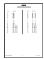
APPENDIX A
INPUT MODULE CONNECTOR DEFINITION
Pin #
1
2
3
4
5
6
7
8
9
10
11
12
13
14
15
16
17
18
19
20
21
22
23
24
25
ULTRACASTER-2000
Definition
Input 1
Input 2
Input 3
Input 4
Input 5
Input 6
Input 7
Input 8
Input 9
Input 10
Input 11
Input 12
Input 13
Input 14
Input 15
Input 16
Input 17
Input 18
Input 19
Input 20
Input 21
Input 22
Input 23
Input 24
Input 25
Pin #
26
27
28
29
30
31
32
33
34
35
36
37
38
39
40
41
42
43
44
45
46
47
48
49
50
30
Definition
Input 26
Input 27
Input 28
Input 29
Input 30
Input 31
Input 32
Busy A - COM
Busy A - NC
Busy A - NO
Busy B - COM
Busy B - NC
Busy B - NO
Ground
Ground
Ground
Ground
Ground
Ground
Ground
Ground
Ground
Ground
Ground
Ground
Rev. 10/15/96
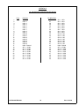
APPENDIX B
I/O MODULE CONNECTOR DEFINITION
Pin #
1
2
3
4
5
6
7
8
9
10
11
12
13
14
15
16
17
18
19
20
21
22
23
24
25
ULTRACASTER-2000
Definition
Input 1
Input 2
Input 3
Input 4
Input 5
Input 6
Input 7
Input 8
Input 9
Input 10
Input 11
Input 12
Input 13
Input 14
Input 15
Input 16
Input - Ground
Input - Ground
Input - Ground
Input - Ground
Input - Ground
Input - Ground
Input - Ground
Input - Ground
Input - Ground
Pin #
26
27
28
29
30
31
32
33
34
35
36
37
38
39
40
41
42
43
44
45
46
47
48
49
50
31
Definition
Out 1 - NC
Out 2 - NC
Out 3 - NC
Out 4 - NC
Out 5 - NC
Out 6 - NC
Out 7 - NC
Out 8 - NC
Out 9 - NC
Out 10 - NC
Out 11 - NC
Out 12 - NC
Out 13 - NC
Out 14 - NC
Out 15 - NC
Out 16 - NC
Out - Ground
Out - Ground
Out - Ground
Out - Ground
Out - Ground
Out - Ground
Out - Ground
Out - Ground
Out - Ground
Rev. 10/15/96
APPENDIX C
I/O 16B MODULE CONNECTOR DEFINITION
Pin #
1
2
3
4
5
6
7
8
9
10
11
12
13
14
15
16
17
18
19
20
21
22
23
24
25
ULTRACASTER-2000
Definition
Input 1
Input 2
Input 3
Input 4
Input 5
Input 6
Input 7
Input 8
Input 9
Input 10
Input 11
Input 12
Input 13
Input 14
Input 15
Input 16
Input - Ground
Out 1 - COM
Out 2 - COM
Out 3 - COM
Out 4 - COM
Out 5 - COM
Out 6 - COM
Out 7 - COM
Out 8 - COM
Pin #Definition
26
27
28
29
30
31
32
33
34
35
36
37
38
39
40
41
42
43
44
45
46
47
48
49
50
32
Out 1 - NO
Out 2 - NO
Out 3 - NO
Out 4 - NO
Out 5 - NO
Out 6 - NO
Out 7 - NO
Out 8 - NO
Out 9 - NO
Out 10 - NO
Out 11 - NO
Out 12 - NO
Out 13 - NO
Out 14 - NO
Out 15 - NO
Out 16 - NO
Input - Ground
Out 9 - COM
Out 10 - COM
Out 11 - COM
Out 12 - COM
Out 13 - COM
Out 14 - COM
Out 15 - COM
Out 16 - COM
Rev. 10/15/96


![RessqM, Enhanced Version of RESSQ [Javandel et al., 1984]](http://vs1.manualzilla.com/store/data/005674408_1-e8a4b9f66c80cdc83d847a710e5b4b1f-150x150.png)