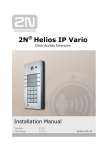
1
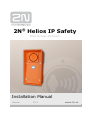
® 2N Helios IP Safety Door Access Intercom Installation Manual Version 1.2.1 www.2n.cz The 2N TELEKOMUNIKACE a.s. joint-stock company is a Czech manufacturer and supplier of telecommunications equipment. The product family developed by 2N TELEKOMUNIKACE a.s. includes intercoms, GSM and UMTS products, private branch exchanges (PBXs) and M2M solution. 2N TELEKOMUNIKACE a.s. has been ranked among the Czech top companies for years and represents a symbol of prosperity in the field of IP intercoms. Furthermore, the company dedicates significant attention to operator solutions as well as to effectively providing support for our distribution network and customer service. At present, we export our products into over 120 countries worldwide and have exclusive distributors on all continents. 2N® is a registered trademark of 2N TELEKOMUNIKACE a.s.. Any product and/or other names mentioned herein are registered trademarks and/or trademarks or brands protected by law. 2N TELEKOMUNIKACE administers the FAQ database to help you quickly find information and to answer your questions about 2N products and services. On faq.2n.cz you can find information regarding products adjustment and instructions for optimum use and procedures „What to do if...“. Declaration of Conformity 2N TELEKOMUNIKACE a.s. hereby declares that the 2N® Helios IP Safety product complies with all basic requirements and other relevant provisions of the 1999/5/EC directive. For the full wording of the Declaration of Conformity see www.2n.cz. 2N TELEKOMUNIKACE company is the owner of the ISO 9001:2008 certificate. All development, production and distribution processes of the company are managed by this standard and guarantee high quality, technical level and professional aspect of all our products. Contents 1. Product Overview............................................................... 1 1.1 Product Description ....................................................................................................... 2 Basic Features.................................................................................................................. 2 Advantages of Use ........................................................................................................... 3 1.2 Upgrade ........................................................................................................................... 4 1.3 2N Helios IP Safety Components and Associated Products.................................... 5 Basic Units ........................................................................................................................ 5 Mounting Accessories ...................................................................................................... 6 VoIP Telephones .............................................................................................................. 7 Electric Locks ................................................................................................................... 7 Power Supply ................................................................................................................... 7 Additional Modules ........................................................................................................... 8 1.4 Terms and Symbols ....................................................................................................... 9 Symbols ............................................................................................................................ 9 ® 2. Description and Installation ............................................ 11 2.1 Before You Start ........................................................................................................... 12 Product Completeness Check ........................................................................................ 12 2.2 Mechanical Installation ................................................................................................ 13 Mounting Type Overview ................................................................................................ 13 Common Mounting Principles ........................................................................................ 15 Surface Mounting ........................................................................................................... 16 Flush Mounting – Classic Bricks .................................................................................... 17 Flush Mounting – Thermally Insulated Wall ................................................................... 18 Flush Mounting – Hollow Bricks ..................................................................................... 19 Flush Mounting – Plasterboard ...................................................................................... 19 Use of Cable Bushings ................................................................................................... 20 2.3 Electric Installation ...................................................................................................... 21 PCB Connectors ............................................................................................................. 21 Mounting Completion ..................................................................................................... 24 3. Function and Use ............................................................. 25 ® 3.1 2N Helios IP Safety Configuration ............................................................................ 26 3.2 Maintenance .................................................................................................................. 27 Cleaning ......................................................................................................................... 27 Future Tag Replacement, Programming Changes ........................................................ 27 4. Technical Parameters ...................................................... 29 4.1 Technical Parameters .................................................................................................. 30 5. Supplementary Information ............................................ 33 5.1 Directives, Laws and Regulations .............................................................................. 34 5.2 Troubleshooting ........................................................................................................... 35 5.3 General Instructions and Cautions ............................................................................ 36 Electric Waste and Used Battery Pack Handling ........................................................... 37 1 1. Product Overview In this section, we introduce the 2N® Helios IP Safety product, outline its application options and highlight the advantages following from its use. Here is what you can find in this section: Product Description Upgrade 2N® Helios IP Safety Components and Associated Products 1 Product Description 1.1 VoIP Telephones 91378350 91378351 Grandstream GXV3140 VoIP video telephone Grandstream GXV3175 VoIP telephone Electric Locks 932070E 932080E 932090E BEFO 1211 12V / 600 mA BEFO 1221 with momentum pin BEFO 1211MB with mechanical blocking 91378100E 91341481E 932928E 91378100US Adapter 12 V/2 A 12 V transformer PoE injector A stabilised power supply has to be used if the Ethernet (PoE) power supply is not available. Power Supply 2 Product Description 1.1 Additional Modules 9151010 9159010 9137410E Additional switch with normally open/closed contact and 12V switched output. Security Relay External IP relay Terms and Symbols 3 Product Description 1.1 1.1 Product Description Basic Features 2N® Helios IP Safety is a highly resistant and reliable IP door access intercom provided with a lot of useful above-standard functions. Supporting the SIP standard and being compatible with the leading IP PBX and telephone suppliers, 2N ® Helios IP Safety can make use of all VoIP services. 2N® Helios IP Safety can work as a standard or emergency door access intercom for buildings, entrances to premises or garages, manufacturing halls, highways and so on. 2N® Helios IP Safety is equipped with two very sensitive microphones and an up to 10W loudspeaker. Thanks to an integrated acoustic echo cancelling (AEC) system, the product provides mutual audibility even of persons talking at the same time under normal conditions. 2N® Helios IP Safety can be (on request) equipped with a colour wide-angle camera, which displays the calling person on the called party’s video telephone or PC monitor. 2N® Helios IP Safety can be provided with 1 or (on request) 2 pre-programmed buttons. You can set up to three telephone numbers and time profiles for each of the buttons to increase the accessibility of the called party. 2N® Helios IP Safety is equipped with an electric lock switch. You can control the switch using a numerical keypad or, during a call, using any telephone set. An additional switch module can be installed if necessary. A wide range of settings allow for a variety of applications. 2N® Helios IP Safety is very easy to install. All you have to do is connect the system into your LAN via a network cable and feed it from a 12V power supply or your PoE supporting LAN. Configure 2N® Helios IP Safety using your PC via any web browser. Use the 2N® Helios IP Manager to manage extensive 2N® Helios IP Safety systems easily and quickly. 4 Product Description 1.1 Advantages of Use Uncompromising AntiVandal design High covering level – up to class IP69K Variable mounting options (brick/plasterboard flush mounting, surface mounting) Sensitive microphone and powerful loudspeaker Bidirectional communication – acoustic echo cancelling Integrated colour camera with wide-angle lens (on request) Integrated electronic lock switches with wide setting options Optional integrated RFID card reader module LAN (PoE) or external 12V power supply Configuration via web interface or dedicated PC application SIP 2.0 support Up to 999 telephone directory positions Up to 20 user time profiles Video codecs (H.263+, H.264, MPEG-4, JPEG) Audio codecs (G.711, G.729) HTTP server for configuration SNTP client for time synchronisation with server RTSP server for video streaming SMTP client for e-mail sending TFTP client for automatic configuration and firmware update 5 Upgrade 1.2 1.2 Upgrade The manufacturer reserves the right to modify the product in order to improve its qualities. Version Changes 6 2N® Helios IP Safety Components and Associated Products 1.3 1.3 2N® Helios IP Safety Components and Associated Products Basic Units 9152101 1 button 9152101W 1 button, 10W loudspeaker, IP69K 2N® Helios IP Safety is designed for outdoor applications and requires no additional roof. Wincluding Part Nos. are intended for WAP pressure cleaning and extremely noisy environments (such as highways, etc.). 2N® Helios IP Safety units can wall mounted without requiring any additional accessories. Use the appropriate mounting box (see below) for plasterboard and flush mounting. 7 2N® Helios IP Safety Components and Associated Products 1.3 Mounting Accessories 9152000 9151001 9151002 Mounting frame Brick flush mounting box orange Stainless steel Plasterboard flush mounting box Aluminum 8 2N® Helios IP Safety Components and Associated Products 1.3 VoIP Telephones 91378350 91378351 Grandstream GXV3140 VoIP video telephone Grandstream GXV3175 VoIP telephone Electric Locks 932070E 932080E 932090E BEFO 1211 12V / 600 mA BEFO 1221 with momentum pin BEFO 1211MB with mechanical blocking 91378100E 91341481E 932928E 91378100US Adapter 12 V/2 A 12 V transformer PoE injector A stabilised power supply has to be used if the Ethernet (PoE) power supply is not available. Power Supply 9 2N® Helios IP Safety Components and Associated Products 1.3 Additional Modules 9151010 9159010 9137410E Additional switch with normally open/closed contact and 12V switched output. Security Relay External IP relay 10 Terms and Symbols 1.4 1.4 Terms and Symbols Symbols Safety Warning Always abide by this information to prevent injury of persons! Warning Always abide by this information to prevent damage to the device. Caution Important information for system functionality. Tip Useful advice. Note Additional information. 11 2 2. Description and Installation In this section we describe the 2N® Helios IP Safety product and its installation. Here is what you can find in this section: Before You Start Mechanical Installation Electric Installation 13 Before You Start 2.1 2.1 Before You Start Product Completeness Check Please check the contents of your 2N® Helios IP Safety delivery: 1 2N® Helios IP Safety (selected model) 1 Torx 10 / Torx 20 double-ended wrench 1 spare sealing for big bushing for a thick cable, one hole 1 big blank with nut 1 this manual 1 mounting template 4 screws 5x80 mm 4 “intelligent” 8x50 mm dowels Notes Mounting frame is not included – it is sold separately as order no. 9152000. Bushing set is the same as for 2N® Helios IP Force, but bushings are already mounted. 14 Mechanical Installation 2.2 2.2 Mechanical Installation Mounting Type Overview Refer to the table below for a list of mounting types and necessary components. 2N® Helios IP Safety is preferably intended for surface mounting. For recessed mounting, it is necessary to order mounting frame or other accessories. Surface mounting (concrete and steel structures, entry barrier columns, etc.) What You Need: Just your 2N® Helios IP Safety unit Recessed mounting – classic bricks What You Need: Frame 9152000 A precisely cut hole or, optionally, the brick flush mounting box, Part No. 9151001 Hole: 132 x 223 x 83mm (with flush mounting box) Hole: 112 x 220 x 70mm (without flush mounting box) Recessed mounting – thermally insulated wall What You Need: Frame 9152000 Longer screws (depending on the thermal insulation thickness) Hole: 112 x 220 x 70mm 15 Mechanical Installation 2.2 Recessed mounting – hollow bricks What You Need: Frame 9152000 Brick flush mounting box, Part No. 9151001 Hole: 132 x 223 x 83mm Flush mounting – plasterboard wall What You Need: Frame 9152000 Plasterboard flush mounting box, Part No. 9151002 Hole: 118 x 235mm Caution The warranty does not apply to the product defects and failures arisen as a result of improper mounting (in contradiction herewith). The manufacturer is neither liable for damages caused by theft within an area that is accessible after the attached electric lock is switched. The product is not designed as a burglar protection device except when used in combination with a standard lock, which has the security function. When the proper mounting instructions are not met, water might get in and destroy the electronics. It is because the intercom circuits are under continuous voltage and water infiltration causes an electro-chemical reaction. The manufacturer’s warranty shall be void for products damaged in this way! 16 Mechanical Installation 2.2 Common Mounting Principles Caution Make sure that the dowel holes have the required diameter. If the diameter is too large, the dowels may get loose. Use some suitable building adhesive to keep the dowels in place. Make sure that the hole depth is sufficient too! The dowel length is 50 mm and the screw length is 80 mm. Remember that dowels of poor quality may easily get loose and fall out of the wall! Stainless steel screws are used for the 2N® Helios IP Safety assembly. Other screws than stainless steel ones corrode soon and may aesthetically deteriorate the surrounding environment! Having removed the front panel, make sure that no dirt gets inside the product (especially onto the sealing surface and microphone sound guides). Note The microphone covers are normally loose after the front panel is removed! The screw is only used as a fall-out protection during installation. 17 Mechanical Installation 2.2 Surface Mounting Wall (surface) mounting is used where flush mounting is inapplicable (in concrete and steel structures, entry barrier columns, etc.). The frame is not used. Caution If there is a risk of vandalism (in public garages, e.g.), use steel fixing elements instead of the dowels and screws included in the delivery. Be sure to insert plugs into unused bushing holes to avoid water leakage during facade cleaning, for example. Never leave the holes open for even a short time (one day delay between mounting and cable connection, e.g.). Safety Warning Eliminate the risk of accident! Wall mounting is not suitable for narrow passages or places where people’s attention may be distracted. The manufacturer shall not be liable for injuries incurred as a result of unsafe mounting! 1. Select the 2N® Helios IP Safety position with respect to the supply cables. Where the cables are installed inside a structure or wall, use the hole at the intercom bottom. 2. Drill holes of the depth of 60 mm for dowels in the wall as shown in the figure. Push or hammer the enclosed dowels into the drilled holes. Use some suitable building adhesive if the dowels are too loose. Use fixing elements of your own for steel structure surface mounting (metric screws + nuts, e.g.). 3. Remove the front panel from the intercom. 4. 2N® Helios IP Safety has bushings already mounted. Replace it with plugs, if unused. 5. Put the intercom on the wall/structure while introducing cables inside. Leave some of the cables inside the unit as a reserve. Insert the plugs in the unused bushings and tighten the bushing nuts carefully. 6. Do not complete mounting until you have finished electrical installation – refer to Mounting Completion. Where cables lead along the surface, use the bushings included in the delivery. 18 Mechanical Installation 2.2 Flush Mounting – Classic Bricks If you use the brick flush mounting box, follow the instructions included in the box. If you do not use the mounting box, follow the instructions below: 1. Make a hole using the template. Suppose that all the required cables have been carried into the hole. 2. Unpack the frame, put the intercom inside and place the set onto the hole to make sure that the hole is deep enough and the uneven edge is perfectly covered with the frame. 3. Push or hammer the enclosed dowels into the drilled holes. Use some suitable building adhesive if the dowels are too loose. 4. Remove the front panel from the intercom. Remove bushings. 5. Select the holes for cable supply. Insert the blanks into the other holes. Apply the cable bushings or a suitable sealant to prevent penetration of insects or water. You can also insert the small bushing in the intercom bottom hole. make sure that the dowel holes are drilled accurately! You will not be able to align considerable inaccuracies with this way of mounting! 6. Put the frame on the intercom. 7. Place the intercom into the hole while introducing the cables. Leave some of the cables inside the unit as a reserve and the rest under the intercom bottom. 8. Insert the enclosed screws in the lateral mounting holes making sure they have penetrated into the dowels. Tighten all the screws properly. Tip: The screw tightening sequence may affect the intercom position. 9. You can seal the frame - wall gap with a silicone or another sealant to avoid wall dampening as a result of water leakage. This additional sealing is unnecessary for the intercom function. 10. Do not complete mounting until you have finished electrical installation – refer to Mounting Completion 19 Mechanical Installation 2.2 Flush Mounting – Thermally Insulated Wall Cut out the thermal insulation layer using the template (the same as for classic brick wall). Caution The hole depth depends on the insulation layer thickness. If the insulation layer is rather thick, you may need longer screws! If there are hollow bricks under the insulation, make sure that your screws pass through the whole dowel (50 mm) and fix the dowel reliably. Make sure that the dowel holes have the required diameter. If the diameter is too large, the dowels may get loose. Use some suitable building adhesive to keep the dowels in place. Make sure that the hole depth is sufficient too! The dowel length is 50 mm and the screw length is 80 mm. Suppose that all the required cables have been carried into the drilled hole. Now follow the instructions applicable for classic brick flush mounting. However, remember that thermally insulated walls show less strength than classic brick walls. 20 Mechanical Installation 2.2 Flush Mounting – Hollow Bricks Suppose you intend to install your 2N® Helios IP Safety unit into a wall made of hollow bricks. Note that the external side of the bricks gets damaged by cutting and the dowels cannot practically be fixed into the thin internal part of the bricks. Therefore, use the brick flush mounting box and follow the instructions included therein. Flush Mounting – Plasterboard Use the plasterboard flush mounting box and follow the instructions included therein. 21 Mechanical Installation 2.2 Use of Cable Bushings The cable bushings included in the 2N® Helios IP Safety delivery are designed for the following cables: Big bushing: for two cables of the diameter of 5–6 mm (UTP cable), or, upon insert replacement, for one thick cable/tube of the diameter of up to 14 mm. Small bushing: for one cable of the diameter of 5–8 mm. Tip Even a LAN cable including the RJ-45 connector can go through the big bushing. See below for instructions. How to Pull a RJ-45 Terminated Cable through a Bushing 1. Unscrew the big bushing nut completely. 2. Remove the sealing including the cover from the bushing. Cut either of the components as shown in the figures. 3. Put the bushing nut on the cable and insert the sealing. 4. Replace the cover onto the sealing. 5. Pull the cable connector though the bushing body into the intercom and clip it into the motherboard connector. 6. Move the sealing including the cover along the cable as far as the bushing body, or add a plug if necessary. 7. Replace and tighten the nut. 22 Electric Installation 2.3 2.3 Electric Installation This subsection describes how to connect 2N® Helios IP Safety into your Local Area Network (LAN) and how to connect supply voltage and the electric lock. PCB Connectors Fig. 2.11 shows the lay-out of connectors on the 2N® Helios IP Safety printed circuit board (PCB). Cables, accessories and other system components are connected to connectors X1 through X22. Figure 2.11 2N® Helios IP Safety Connectors, PCB Version 555v2 and 555v3 23 Electric Installation 2.3 Description of Connectors X1 Loudspeaker X4 Camera module X5 Button 1 SW1 Reset button (555v3 version only) X6 Configuration jumpers X8 Extending module (RFID card reader or additional switch) X10 Buttons 1 through 4 X11 LAN X12 Servicing connector X13 Keypad module X15 Left-hand microphone X16 Right-hand microphone X17 Relay NO and NC contact X18 12V/700 mA switched output X19 12V/1A DC power input LED1/2 System status indicators LED3 LAN connection activity indicator LAN Connection 2N® Helios IP Safety is connected to the LAN via a RJ-45 terminated (connector X11) UTP/STP cable (of category Cat 5e or higher). The system is equipped with the AutoMDIX function and so both the straight and crossed cable versions can be used. External Power Supply Connection 2N® Helios IP Safety can be fed either from an external 12V/1A DC power supply or from the LAN equipped with the PoE 802.3af supporting network elements. External Power Supply An external 12V power supply is connected to terminal block X19. Use a 12V +- 15% DC power source dimensioned to current intake of 1A at least (Part No. 91341481E) to ensure a reliable function of your device. PoE Supply 2N® Helios IP Safety is compatible with the PoE 802.3af (Class 0 – 12.95W) technology and can be supplied directly from the LAN via compatible network elements. If your LAN in incompatible, insert the PoE injector, Part No. 91758100E, between 2N® Helios IP Safety and the nearest network element. 24 Electric Installation 2.3 Electric Lock Connection 2N® Helios IP Safety is equipped with an electrically isolated relay switch with NO and NC contacts (terminal block X17) and 12V/700mA switched output (terminal block X18), to which a standard electric lock or another compatible electrical appliance can be connected. Information Devices with PCB version 555v3 and higher provides independent control of 12V switched output (terminal block X18) and relay switch (terminal block X17). Devices with PCB version 555v2 have both outputs switched simultaneously. Factory Default Resetting (PCB version 555v3) For resetting device to default settings press and hold SW1 button. Wait for the first sound signalization and then release the button. If you press the button for short time device will reboot only. SW1 button is available in devices with PCB version 555v3 and higher. For devices with PCB version 555v3 see procedure below. Factory Default Resetting (PCB version 555v2) 1. Disconnect the device from the power supply. 2. Move the short-circuit jumper on connector X6 into the Default setup position. Configuration jumpers (X6) are located in the right-hand upper corner of the PCB. 3. Reconnect the power supply and wait for a start signalling sound. 4. Disconnect the device from the power supply. 5. Move the short-circuit jumper on connector X6 into the Normal operation position. 6. Reconnect the power supply. The device will be reset to factory default. Normal operation Default setup Connector X6 25 Electric Installation Table 2.1 2.3 Configuration Jumpers X6 Mounting Completion 1. Having connected all the wires, make sure that the bushings, if used, are tightened properly and the RJ-45 connector is inserted in the PCB connector. 2. Connect the pushbutton cable (to X5) and place the front cover carefully. Make sure that the connector is inserted correctly and the wires inside the device leave enough space for the board if you are installing a four-button board. Tighten the four screws thoroughly with the wrench enclosed (Torx 20) to make the panel fit tightly to the metal chassis. Caution An incorrect mounting may compromise the intercom watertightness. Water leakage may damage the electronic part of the system. Stainless steel screws are used for the 2N® Helios IP Safety assembly. Other screws than stainless steel ones corrode soon and may aesthetically deteriorate the surrounding environment! 26 3 3. Function and Use In this section we describe the basic and extending functions of the 2N® Helios IP Safety product. Here is what you can find in this section: Configuration Maintenance 27 2N® Helios IP Safety Configuration 3.1 3.1 2N® Helios IP Safety Configuration Use a PC equipped with any web browser to configure 2N® Helios IP Safety: Launch your web browser (Internet Explorer, Firefox, etc.). Enter the IP address of your intercom (http://192.168.1.100/, e.g.). Log in using the Admin user name and 2n password. You have to know the IP address of your device to log in to the integrated web server. By default, 2N® Helios IP Safety is switched into the dynamic IP address mode, i.e. it obtains the IP address automatically if a properly set DHCP server is available in your LAN. If no such DHCP server is available, you can operate 2N® Helios IP Safety in the static IP address mode. Refer to the 2N® Helios IP Configuration Manual for configuration details. If your device remains inaccessible (you have forgotten the IP address, or the LAN configuration has changed, for example), change the LAN settings using the buttons on the device. Switching between Static and Dynamic IP Address Connect 2N® Helios IP Safety to the power supply (or, disconnect and reconnect it if already connected). Wait for the first acoustic signal Press button 1 15 times. The acoustic signal Wait until the device is restarted automatically. . indicates mode switching. Note: The 15 times 1 sequence must be entered within 30 seconds after the first sound signal for security reasons. The inter-digit delay may be 2s at most. The static IP address mode will be switched into the dynamic IP address mode and vice versa upon restart. 28 Maintenance 3.2 3.2 Maintenance Cleaning If used frequently, 2N® Helios IP Safety gets dirty. To clean it, use a piece of soft cloth moistened with clean water. We recommend you to obey the following principles while cleaning: Never use aggressive detergents (such as abrasives or strong disinfectants). Use suitable cleaning agents for glass lens cleaning (cleaners for glasses, optic devices screens, etc.). Alcohol-based cleaners may be applied. Clean the device in dry weather in order to make waste water evaporate quickly. Tip The 2N® Helios IP Safety models of Part Nos. 9151101W and 9151101CW may be cleaned with WAP high pressure washers. Future Tag Replacement, Programming Changes For necessary steps refer to the preceding subsections. Keep the following for future changes: This manual Unused transparent foil strips for button tags Always use the product for the purpose it was designed and manufactured for, in compliance herewith. The manufacturer reserves the right to modify the product in order to improve its qualities. 2N Helios IP Safety contains no environmentally harmful components. When the product‘s service life is exhausted and you would like to dispose of it please do so in accordance with applicable legal regulations. 29 4 4. Technical Parameters In this section we describe the technical parameters of the 2N® Helios IP Safety product. 31 Technical Parameters 4.1 4.1 Technical Parameters Signalling protocol SIP Buttons Button design Count of buttons Numerical keypad Industrial waterproof, stainless steel, vandal resistant pushbutton, blue backlit 1 (2 on request) (on request) Microphone Amplifier Loudspeaker Volume control Full duplex 2 integrated microphones 10W (class D) 1W (optionally 10W) Adjustable with automatic adaptive mode Yes (AEC) Audio Audio stream Protocols Codecs RTP/RTSP G.711, G.729 Interface Power supply PoE LAN Recommended cabling Passive switch Active switch output 12V+-15%/1A DC or PoE PoE 802.3af (Class 0 - 12.95W) 10/100BASE-TX s Auto-MDIX, RJ-45 Cat-5e or higher NO and NC contacts, up to 30V/1A AC/DC 12V/700mA DC Mechanical properties Cover Colour Working temperature Working relative humidity Storing temperature Dimensions Robust aluminium cast product Weight Covering level netto max. 2 kg / brutto max. 2,5 kg RAL 2004 (orange) -40°C to 55°C 10% - 95% (non-condensing) -40°C to 70°C 217x109x83 mm 242x136x83 mm incl. frame IP65 , IP69K (91521xxxW) 32 Technical Parameters 4.1 Declaration of Conformity 2N TELEKOMUNIKACE a.s. hereby declares that this product complies with all basic requirements and other relevant provisions of the 1999/5/EC directive. For the full wording of the Declaration of Conformity see www.2n.cz. Industry Canada This Class B digital apparatus complies with Canadian ICES-003. Cet appareil numérique de la classe B est conforme à la norme NMB-003 du Canada. This device complies with part 15 of the FCC Rules. Operation is subject to the following two conditions: (1) This device may not cause harmful interference, and (2) this device must accept any interference received, including interference that may cause undesired operation. Note This equipment has been tested and found to comply with the limits for a Class B digital device, pursuant to part 15 of the FCC Rules. These limits are designed to provide reasonable protection against harmful interference in a residential installation. This equipment generates, uses and can radiate radio frequency energy and, if not installed and used in accordance with the instructions, may cause harmful interference to radio communications. However, there is no guarantee that interference will not occur in a particular installation. If this equipment does cause harmful interference to radio or television reception, which can be determined by turning the equipment off and on, the user is encouraged to try to correct the interference by one or more of the following measures: Reorient or relocate the receiving antenna Increase the separation between the equipment and receiver Connect the equipment into an outlet on a circuit different from that to which the receiver is connected Consult the dealer or an experienced radio/TV technician for help. Caution Changes or modifications to this unit not expressly approved by the party responsible for compliance could void the user’s authority to operate this equipment. Always use the product for the purpose it was designed and manufactured for, in compliance herewith. The manufacturer reserves the right to modify the product in order to improve its qualities. This device contains no environmentally harmful components. When the product‘s service life is exhausted and you would like to dispose of it please do so in accordance with applicable legal regulations. 33 5 5. Supplementary Information This section provides supplementary information on the 2N® Helios IP Safety product. Here is what you can find in this section: Applicable Directives, Laws and Regulations 35 Directives, Laws and Regulations 5.1 5.1 Directives, Laws and Regulations 2N® Helios IP Safety conforms to the following directives and regulations: Directive 1999/5/EC of the European Parliament and of the Council, of 9 March 1999 – on radio equipment and telecommunications terminal equipment and the mutual recognition of their conformity Directive 2006/95/EC of the European Parliament and of the Council of 12 December 2006 on the harmonisation of the laws of Member States relating to electrical equipment designed for use within certain voltage limits Directive 2004/108/EC of the Council of 15 December 2004 on the harmonisation of the laws of Member States relating to electromagnetic compatibility Directive 2002/95/EC of the European Parliament and of the Council of 27 January 2003 on the restriction of the use of certain hazardous substances in electrical and electronic equipment Regulation (EC) No. 1907/2006 of the European Parliament and of the Council of 18 December 2006 concerning the Registration, Evaluation, Authorisation and Restriction of Chemicals (REACH), establishing a European Chemicals Agency, amending Directive 1999/45/EC and repealing Council Regulation (EEC) No. 793/93 and Commission Regulation (EC) No. 1488/94 as well as Council Directive 76/769/EEC and Commission Directives 91/155/EEC, 93/67/EEC, 93/105/EC and 2000/21/EC Directive 2011/65/EU of the European Parliament and of the Council of 8 June 2011 on waste electrical and electronic equipment. Commission Regulation (EC) No. 1275/2008, of 17 December 2008, implementing Directive 2005/32/EC of the European Parliament and of the Council with regard to ecodesign requirements for standby and off mode electric power consumption of electrical and electronic household and office equipment 36 Troubleshooting 5.2 5.2 Troubleshooting For tips concerning solutions of other potential problems see faq.2n.cz. 37 General Instructions and Cautions 5.3 5.3 General Instructions and Cautions Please read this User Manual carefully before using the product. Follow all instructions and recommendations included herein. Any use of the product that is in contradiction with the instructions provided herein may result in malfunction, damage or destruction of the product. The manufacturer shall not be liable and responsible for any damage incurred as a result of a use of the product other than that included herein, namely undue application and disobedience of the recommendations and warnings in contradiction herewith. Any use or connection of the product other than those included herein shall be considered undue and the manufacturer shall not be liable for any consequences arisen as a result of such misconduct. Moreover, the manufacturer shall not be liable for any damage or destruction of the product incurred as a result of misplacement, incompetent installation and/or undue operation and use of the product in contradiction herewith. The manufacturer assumes no responsibility for any malfunction, damage or destruction of the product caused by incompetent replacement of parts or due to the use of reproduction parts or components. The manufacturer shall not be liable and responsible for any loss or damage incurred as a result of a natural disaster or any other unfavourable natural condition. The manufacturer shall not be held liable for any damage of the product arising during the shipping thereof. The manufacturer shall not make any warrant with regard to data loss or damage. The manufacturer shall not be liable and responsible for any direct or indirect damage incurred as a result of a use of the product in contradiction herewith or a failure of the product due to a use in contradiction herewith. All applicable legal regulations concerning the product’s installation and use as well as provisions of technical standards on electric installations have to be obeyed. The manufacturer shall not be liable and responsible for damage or destruction of the product or damage incurred by the consumer in case the product is used and handled contrary to the said regulations and provisions. The consumer shall, at its own expense, obtain software protection of the product. The manufacturer shall not be held liable and responsible for any damage incurred as a result of the use of deficient or substandard security software. The consumer shall, without delay, change the access password for the product after installation. The manufacturer shall not be held liable or responsible for any damage incurred by the consumer in connection with the use of the original password. The manufacturer also assumes no responsibility for additional costs incurred by the consumer as a result of making calls using a line with an increased tariff. 38 General Instructions and Cautions 5.3 Electric Waste and Used Battery Pack Handling Do not place used electric devices and battery packs into municipal waste containers. An undue disposal thereof might impair the environment! Deliver your expired electric appliances and battery packs removed from them to dedicated dumpsites or containers or give them back to the dealer or manufacturer for environmental-friendly disposal. The dealer or manufacturer shall take the product back free of charge and without requiring another purchase. Make sure that the devices to be disposed of are complete. Do not throw battery packs into fire. Battery packs may not be taken into parts or shirt-circuited either. 39 2N TELEKOMUNIKACE a.s. Modřanská 621, 143 01 Prague 4, Czech Republic Tel.: +420 261 301 500, Fax: +420 261 301 599 E-mail: [email protected] Web: www.2n.cz 1788