1
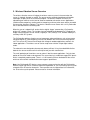
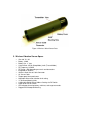
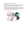
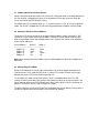
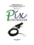
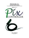
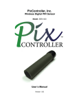
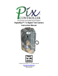
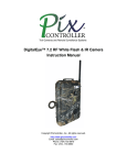
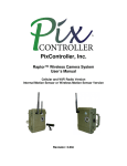
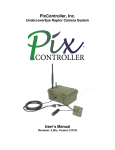
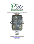
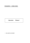
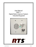
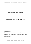
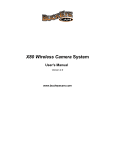
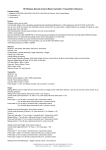
PixController, Inc.
Wireless Vibration Sensor
For Indoor and Outdoor Use
Model: SEN-440
User’s Manual
Version 1.00
WARRANTY REGISTRATION
PixController, Inc. warrants products sold by it and guarantees to correct, by repair or
replacement at our option, any defects of material and workmanship which develop under normal
and proper use within six (6) months from the date of the original purchase when inspection
proves the fault to be of manufacturing. Some circuit board components only receive a twelve
(12) month warranty. All such Products must be returned to our service center.
This warranty does not apply to any of our Products which have been repaired or altered by
unauthorized persons or service centers in any way so as, in our judgment, to injure their stability
or reliability, or which have been subject to misuse, negligence, or accident or which have had
their serial number altered, effaced or removed.
We will not assume any expense or liability for repairs made by other parties without our written
consent. PixController, Inc is not responsible for damage to any associated equipment or
apparatus, nor shall we be held liable for loss of profit or other special damages. There is no
other guarantee or warranty except as herein stated.
Returns for any unaffected products are permitted within 14 days from the date of receipt of
merchandise. After such time, items will incur a 15% restocking fee. Returns of wrong ordered
items are allowed. Returned merchandise will be accepted only if all conditions are met.
In no event shall PixController, Inc. be liable for any incidental, special, indirect or consequential
damages, whether resulting from the use, misuse, or inability to use this product or from defects
in this product. The Buyer is not permitted to tamper or remove any of the Raptor System
electronics without voiding this warranty.
The Buyer, his employees, or others assumes all risks and liabilities for the operation, the use
and the misuse of the product described herein and agree to defend and to save the seller
harmless from any and all claims arising from any cause whatsoever, including seller’s
negligence for personal injury incurred in connection with the use of the said product.
PixController, Inc reserves the right to discontinue models at any time or change specifications,
price or design without notice and without incurring any obligation.
The express warranties are in lieu of all other warranties, guarantees, promises, affirmations, or
representations, express or implied which would be deemed applicable to the goods sold
hereunder. No express warranties and no implied warranties, whether of merchantability, fitness
for any particular use or purpose, against infringement, or otherwise (except as to title) other than
those expressly set forth herein, shall apply.
FOR REPAIR CONTACT
PixController, Inc.
1056 Corporate Lane
Export, PA 15632
Phone: 724-733-0970
Fax: 724-733-0860
Email: [email protected]
Web : http://www.pixcontroller.com
Table of Contents
1. Warranty Information
2. Wireless Vibration Sensor Overview
3. Wireless Vibration Sensor Specs
4. Removing and Replacing the Battery
5. Powering on the Wireless Vibration Sensor
6. Programming the Wireless Vibration Sensor DIP Switches
6.1
6.2
6.3
6.4
Powering On/Off the Wireless Sensor
Setting the Wireless Sensor Address
Setting Range-Test Mode
Adjusting the Digital PIR Sensitivity
7. Wireless Pressure Vibration Mounting Options
2. Wireless Vibration Sensor Overview
The wireless vibration sensor will trigger the wireless camera system in the event when the
sensor is shocked, vibrated, or moved. The sensor can be screwed, placed down with double
sided tape, or epoxy on to the surface of the object. The wireless vibration sensor has an
adjustable gram meter to set the level of vibration needed to activate the sensor. Applications
include mail box tampering, vending machine tampering, and many other areas where you would
like to monitor vibrations of objects. The wireless vibration sensor comes with a 16' fly lead cable
that is connected to the transmitting tube.
When the sensor is tripped it will send a wireless digital “trigger” command to a PixController
wireless RF camera system. This includes, but not limited to the UndercoverEye™ Product line,
Raptor Camera Wireless Sensor Version, DigitalEye™ RF, DVREye™ RF, Remote VideoEye™,
and Sony LANC RF Systems.
The PixController wireless vibration sensor incorporates advanced features such as long range
low power digital RF (radio frequency) transmission between the sensor and receiving camera
unit. This ensures RF transmission through thick foliage for outdoor applications and walls for
indoor applications. The wireless sensor can be setup to transmit four unique digital address
codes.
The electronics were designed to be extremely battery efficient. Using 3 standard AAA alkaline
batteries the sensor can be used in the field up to one year with standard use.
The small packaging of the wireless sensor makes it ideal for covert applications. Only the front
portion of the sensor needs to be exposed. The sensor housing is made from rugged PVC plastic
which is completely weather proof. There is a ¼-20” mounting hole on the bottom of the sensor
which can be used with standard bullet camera-type tri pod mounts.
Note: Any PixController RF wireless sensor camera system can function with the PixController
Wireless Digital PIR Sensor. Products sold before September 15, 2011 will need to have a crystal
changed on the RF receiver electronics. These products can be shipped back to PixController,
Inc. to have the crystal replaced. Please contact us for more information.
Figure 1: Wireless Switch Sensor Parts
3. Wireless Vibration Sensor Specs
•
•
•
•
•
•
•
•
•
•
•
•
•
•
•
•
Size: 6.0” X 1.30”
Battery: 3 AAA
Battery Life: ~1 Year
Current Draw: 107uA (Sleep Mode), 4mA (Transmit Mode)
RF Frequency: 315MHz
RF Range: ~100’ depending on terrain and obstructions
Integrated RF Antenna
Stainless Steel Sensor Cable Connector
16’ Sensor Cable
Tamper-proof, dust-proof cover
Adjustable Gram-meter vibration level setting
¼”-20 Screw Mounting Hole
4 Adjustable Digital Sensor Address Settings via DIP Switch
Power on/off via DIP Switch
LED indicator for testing battery, walk-test, and range-test modes.
Rugged PVC Waterproof Housing
4. Removing and Replacing the Battery
To remove or replace the battery in the wireless sensor unit simply pull off the rubber battery
cover located at the rear of the sensor. A 3 AAA battery holder will slide out. Removing the
battery will be necessary to power the unit on/off, change DIP switch programming settings, and
replacing the batteries.
Figure 2 shows how the battery cover and battery is removed, and Figure 3 shows the DIP
switches inside of the sensor tube.
Figure 2: Replacing/Removing Battery
Figure 3: Digital PIR Sensor DIP Switch & LED
5. Powering on the Wireless Vibration Sensor
To power the wireless senor on you must first remove the battery cover and battery holder from
the sensor tube as shown above. Using a small screw driver such as a jewelers screw driver
press on switch 1 on the DIP switches as shown in Figure 4. The switches are rocker type
switches and you will need to press switch 1 at the top of the switch.
When the sensor is powered on you will notice the LED turn on and blink 5 times. This will let you
know that the wireless sensor is going into a 1-minute walk-test mode. If you place your hand in
front of the senor the LED will blink giving you feedback that the PIR sensor is functioning. After 1
minute has expired the LED will blink 5 more times and exit walk-test mode. From this point on
there will be no LED activity, but the sensor is armed and active.
Figure 4: Adjusting DIP Switch Settings
6. Programming the Wireless Vibration Sensor DIP Switches
The wireless sensor can easily be programmed by adjusting the small switches on the “DIP
Switch” (see Figure 5). The sensor is powered on/off by the DIP Switch, and you can also adjust
the wireless sensor address and PIR detection sensitivity.
Figure 5: DIP Switch
Figure 5a: DIP Switch Functions
6.1 Powering On/Off the Wireless Sensor
Switch 1 will power on/off the wireless PIR sensor unit. Putting the switch in the down position will
turn the senor off, and putting the sensor in the up position will turn the sensor on. When the
sensor is turned on the LED will blink 5 times.
The default setting is all switches down (2 – 7), assuming switch 1 is “on” for sensor in operation
mode. The sensor is shipped with the PIR sensitivity programmed in medium sensitivity mode.
6.2 Setting the Wireless Sensor Address
The wireless PIR sensor can be set to send out 4 different address codes (A through D). DIP
switches 2 & 3 are used to set the sensor address. Setting the sensor address code is useful
when using multiple sensors with multiple camera units. Camera units can be set to respond to
certain sensor addresses.
Sensor Address
Switch 2
Switch 3
---------------------------------------------------------Address A
Down
Down
Address B
Down
Up
Address C
Up
Down
Address D
Up
Up
Note: When changing the sensor address you will need to power the sensor off and back on to
take effect.
6.3 Setting Range-Test Mode
Range-Test mode puts the sensor into a mode where it will send out trigger commands on 2second intervals. In this mode the PIR sensor is inactive. This mode is used to set the range
between the wireless PIR sensor and the receiving unit.
To set Range-Test mode start with the wireless sensor in the power down state. Turn DIP
switches 2 and 3 into the down “off” position. Next, power the sensor on by turning switch 1 into
up “on” position. Wait for the LED to blink 5 times. Next, move switches 2 and 3 into the up “on”
position. The wireless sensor is now in Range-Test mode.
To take the wireless sensor out of Range-Test mode power the sensor down by turning switch 1
into the “off” position then turning switch 2 and 3 into the “off” position.
.
7. Wireless Vibration Sensor Mounting Options
There are several mounting options for the wireless sensor. There is a ¼-20” mounting hole on
the bottom of the sensor which can be used with bullet camera tri pod mounts. The sensor can
also be placed on the ground, but keep in mind that elevating the sensor will increase PIR
detection range and range between the wireless sensor and recording electronics.
Figure 6: Using Bullet Camera Tri Pod Mounts