1
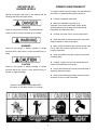
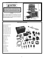
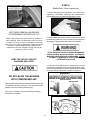
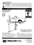
Forward this manual to all operators.
Failure to operate this equipment as
directed may cause injury or death.
Rev A 12-15-08
INSTALLATION AND OPERATION MANUAL
MODEL RL-8500
COMBINATION
BRAKE LATHE
FOR RESURFACING
AUTOMOBILE
AND LIGHT TRUCK
DRUMS, ROTORS
AND FLYWHEELS
Keep this operation manual near the
machine at all times. Make sure that
ALL USERS read this manual .
SHIPPING DAMAGE CLAIMS
When this equipment is shipped, title passes to the
purchaser upon receipt from the carrier. Consequently,
claims for the material damaged in shipment must be
made by the purchaser against the transportation
company at the time shipment is received.
BE SAFE
Your new Ranger brake lathe was designed and
built with safety in mind. However, your overall
safety can be increased by proper training and
thoughtful operation on the part of the operator.
DO NOT operate or repair this equipment
without reading this manual and the important
safety instructions shown inside.
1645 Lemonwood Dr.
Santa Paula, CA. 93060, USA
Tel: 1-805-933-9970
Toll Free 1-800-253-2363
Fax: 1-805-933-9160
www.rangerproducts.com
RL-8500 COMBINATION BRAKE LATHE
RECORD HERE THE FOLLOWING INFORMATION
WHICH IS LOCATED ON THE SERIAL NUMBER DATA PLATE
Serial No. __________
Model No. __________
Manufacturing Date __________
PURCHASE RECORD
Purchased Through ( Distributor ) ____________________________________________
Distributor Address _______________________________________________________
Distributor Phone _______________________
RANGER RL-8500 BRAKE LATHE
STANDARD FACTORY WARRANTY
TERMS
Ranger Products warrants each new RL-8500 Brake Lathe to be free from defects in material and workmanship
for a period of 12 months from the date of purchase to the original equipment owner under normal use and service.
The labor and service call charges to correct a factory manufacturing defect is covered by this warranty for a period of 90 days.
Brake Lathe accessory items are warranted to be free from defects in material and workmanship for a period of 90 days
including labor and service call charges.
THESE WARRANTIES DO NOT EXTEND TO…
defects caused by ordinary wear, abuse, misuse, shipping damage, improper installation or lack of required maintenance.
This warranty is exclusive and in lieu of all other warranties expressed or implied. In no event shall Ranger Products be liable for
special, consequential or incidental damages for the breach or delay in performance of the warranty. Ranger Products
reserves the right to make design changes or add improvements to its product line without incurring any obligation to
make such changes on product sold previously. Warranty adjustments within the above stated policies are based on the
model and serial number of the equipment. This data must be furnished with all warranty claims.
DISCLAIMER OF CONSEQUENTIAL DAMAGES
Ranger Products shall not be liable for consequential damages arising out of or in connection with its products.
Consequential damages shall include, without limitation, loss of use, income, or profit, loss sustained as the result of injury
(including death) to any person, or loss of or damage to property (including property handled, processed or tested by our products).
NOTE: The equipment registration card must be completed and returned to the factory for warranty to be valid.
THE INFORMATION ABOVE MUST BE PROVIDED
FOR ALL SERVICE AND WARRANTY CLAIMS.
2
TABLE OF CONTENTS
Contents
Page #
Failure to follow danger, warning, and caution
instructions may lead to serious personal injury or death
to operator or bystander or damage to property.
Warranty . . . . . . . . . . . . . . . . . . . . . . . . . . . . . .2
Owner’s Responsibility . . . . . . . . . . . . . . . . . . . . . . . . .4
Definitions of Hazard Levels . . . . . . . . . . . . . . . . . . . . 4
Warning Instructions . . . . . . . . . . . . . . . . . . . . . . . . . . . 5
Before You Begin . . . . . . . . . . . . . . . . . . . . . . . . . . . . .5
Electrical Requirements . . . . . . . . . . . . . . . . . . . . . . . .5
Important Safety Instructions . . . . . . . . . . . . . . . . . . . . 6
Features . . . . . . . . . . . . . . . . . . . . . . . . . . . . . . . . . . . 7
Specifications . . . . . . . . . . . . . . . . . . . . . . . . . . . . . 7
Location/ Tooling Package. . . . . . . . . . . . . . . . . . . 8
Assembly View . . . . . . . . . . . . . . . . . . . . . . . . . . . . . .9
Overview
Step 1 - Installation . . . . . . . . . . . . . . . . . . . . . . . . . .10
Step 2 - Basic Set Up. . . . . . . . . . . . . . . . . . . . . . . .11
Step 3 - Basic Operation. . . . . . . . . . . . . . . . . . . . . . . . . . .12
Step 4 - Brake Rotor/Drum Inspection. . . . . . . . . . . . . . .13
Step 5 - Mounting the Quick Change Adapter. . . . . . . . .14
Set Up Configuration Guide . . . . . . . . . . . . . . . . . . . . .15
Rotors
Step 6 - Reconditioning Brake Rotors. . . . . . . . . . . . . . . .16
Step 7 - Mounting the Rotor. . . . . . . . . . . . . . . . . . . . .18
Step 8 - Making the Rotor Scratch Cut . . . . . . . . . . . . . . .19
Step 9 - Machining the Rotor. . . . . . . . . . . . . . . . . . . . . . .21
Step 10 - Mounting a Composite Rotor . . . . . . . . . . . .23
Drums
Step 11 - Boring Bar Set Up (Drum) . . . . . . . . . . . .26
Step 12 - Drum Mounting. . . . . . . . . . . . . . . . . .26
Step 13 - Making the Drum Scratch Cut . . . . . . . . . . . 28
Step 14 - Machining the Drum. . . . . . . . . . . . . . . . . . . . . . .30
Flywheel
Step 15 - Boring Bar Set Up (Flywheel) . . . . . . . . . . . .32
Step 16 - Mounting the Flywheel . . . . . . . . . . . . . . . .32
Step 17 - Scratch Cut on The Flywheel . . . . . . . . . . . 33
Step 18 - Machining the Flywheel. . . . . . . . . . . . . . . . . .35
Maintenance
Step 19 - Spindle Speed Adjustment. . . . . . . . . . . . . . . .37
Step 20 - Feed Motors Belt Replacement . . . . . . . . . . . .38
Step 21- Maintenance . . . . . . . . . . . . . . . . . . . . . . . . . . .40
Parts Listing / Motor Feed Assembly . . . . . . . . . . . . . . .42
Parts Listing / Drum Feed Assembly. . . . . . . . . . .44
Parts Listing / Crossfeed Assembly. . . . . . . . . . . . . . . . . 46
Parts Listing / Main Motor . . . . . . . . . . . . . . . . . 48
Parts Listing / Spindle Assembly. . . . . . . . . . . . 50
Do not operate this machine until you read and
understand all the dangers, warnings and cautions
in this manual.
For additional copies
or further information, contact:
BendPak Inc. / Ranger Products
1645 Lemonwood Dr.,
Santa Paula, CA. 93060
1-805-933-9970
www.bendpak.com
OPERATOR PROTECTIVE
EQUIPMENT
Personal protective equipment helps make resurfacing
safer. However, equipment does not take the place of safe
operating practices. Always wear durable work
clothing during service activity. Shop aprons or shop coats
may also be worn, however loose fitting clothing should
be avoided. Tight fitting leather gloves are recommended
to protect operators hands when handling brake parts.
Sturdy leather work shoes with steel toes and oil resistant
soles should be used by all service personnel to help
prevent injury in typical shop activities.
Eye protection is essential during rotor resurfacing. Safety
glasses with side shields, goggles, or face
shields are acceptable. Back belts provide
support during lifting activities and are also
helpful in providing operator protection.
Consideration should also be given to the
use of hearing protection if brake service
activity is performed in an enclosed area, or if noise levels
are high.
THIS SYMBOL POINTS OUT IMPORTANT SAFETY INSTRUCTIONS WHICH IF NOT FOLLOWED
COULD ENDANGER THE PERSONAL SAFETY AND/OR PROPERTY OF YOURSELF AND OTHERS
AND CAN CAUSE PERSONAL INJURY OR DEATH. READ AND FOLLOW ALL INSTRUCTIONS IN
THIS MANUAL BEFORE ATTEMPTING TO OPERATE THIS MACHINE.
3
DEFINITION OF
HAZARD LEVELS
OWNER’S RESPONSIBILITY
To maintain machine and user safety, the responsibility of
the owner is to read and follow these instructions:
Identify the hazard levels used in this manual with the
following definitions and signal words:
Follow all installation instructions.
Make sure installation conforms to all
applicable Local, State, and Federal Codes, Rules,
and Regulations; such as State and Federal OSHA
Regulations and Electrical Codes.
DANGER
Watch for this symbol: It Means: Immediate hazards
which will result in severe personal injury or death.
Carefully check the unit for correct initial function.
Read and follow the safety instructions. Keep them
readily available for machine operators.
Make certain all operators are properly trained, know
how to safely and correctly operate the unit, and are
properly supervised.
WARNING
Watch for this symbol: It Means: Hazards or unsafe
practices which could result in severe personal injury or
death.
Allow unit operation only with all parts in place and
operating safely.
Carefully inspect the unit on a regular basis and
perform all maintenance as required.
CAUTION
Watch for this symbol: It Means: Hazards or unsafe
practices which may result in minor personal injury or
product or property damage.
Service and maintain the unit only with authorized or
approved replacement parts.
Keep all instructions permanently with the unit and
all decal’s on the unit clean and visible.
Watch for this symbol! It means BE ALERT!
Your safety, or the safety of others, is involved!
4
WARNING INSTRUCTIONS
BEFORE YOU BEGIN
1. This equipment incorporates parts such as electrical
switches which tend to produce sparks. When located in
a service facility, the unit should be in a ventilated room or
enclosure provided for the purpose, or should be at least 18
inches or more above floor to minimize the risk of igniting
fuel vapors.
Receiving:
The shipment should be thoroughly inspected as soon as it
is received. The signed bill of lading is acknowledgement by
the carrier of receipt in good condition of shipment covered
by your invoice. If any of the goods called for on this bill of
lading are shorted or damaged, do not accept them until the
carrier makes a notation on the freight bill of the shorted or
damaged goods. Do this for your own protection.
2. Eye and face protection is required and strongly
recommended: “Protective eye and face equipment is
required to be used where there is a reasonable probability
of injury that can be prevented by use of such equipment.”
OSHA 1910.133 (a) Protective goggles, safety glasses, or
a face shield must be provided by the purchaser/user and
worn by the operator of the equipment. Make sure all eye
and face safety precautions are followed by the operator(s).
Keep bystanders out of the area.
NOTIFY THE CARRIER AT ONCE if any hidden loss or
damage is discovered after receipt and request the carrier
to make an inspection. If the carrier will not do so, prepare
a signed statement to the effect that you have notified the
carrier (on a specific date) and that the carrier has failed to
comply with your request.
IT IS DIFFICULT TO COLLECT FOR LOSS OR DAMAGE
AFTER YOU HAVE GIVEN THE CARRIER A CLEAR
RECEIPT. File your claim with the carrier promptly. Support
your claim with copies of the bill of lading, freight bill,
invoice, and photographs, if available. Our willingness to
assist in helping you process your claim does not make
Ranger Products responsible for collection of claims or
replacement of lost or damaged materials.
3. Do not remove any safety equipment such as guards,
control switches or shut-off devices.
4. Make sure rotors/drums/flywheels are properly mounted
and square before starting the lathe. Check to make sure
all parts are secure.
5. Make sure the rotors/drums/flywheels are clean and
mounted properly before operating lathe.
ELECTRICAL REQUIREMENTS
6. Do not overload the lathe. Read and understand the
lathe capabilities prior to operation. Overloading the lathe
shortens the life of the unit, and could cause a failure
resulting in personal injury.
THIS UNIT CAN BE POWERED WITH 110 VOLTS OR
220 VOLTS. THE VOLTAGE SELECTOR SWITCH
MUST BE SET PRIOR TO OPERATION !
SEE PAGE 10 FOR SWITCH LOCATION.
7. Check damaged parts carefully. Before further use of the
lathe, a guard or other part that is damaged should be
carefully checked. Immediately replace all damaged,
missing, or non-functional parts. Check for alignment of
moving parts, binding of moving parts, breakage of parts,
mounting, and any other conditions that may affect
operation. Guards and other parts that are damaged should
be properly repaired or replaced before lathe is used
again.
For 110 Volt operation, his unit requires power from a 15
amp 110 volt circuit. The lathe must be properly grounded to
protect the operator from shock. The RL-8500 is equipped
with an approved power cord and 3-prong grounding-type
plug. Should an extension cord be required, be sure to use
a similar size power cord with 3-prong grounding plug and
a 3-prong grounding receptacle properly rated to handle
the electrical requirement of this unit. Do not modify a cord
or plug to match a receptacle; have a qualified electrician
install an appropriate outlet to match the lathe
requirements. Repair or replace any worn or damaged
power cords immediately.
8. Always feed the blade or cutter into the work and against
the direction of rotation. Cutters and tool bits are designed
to begin the cut from near the center of the rotor/drum/
flywheel to the outer edge. Do not attempt to cut from the
outside edge into the center.
IMPORTANT NOTE !
9. Never leave the brake lathe running unattended. Turn
the power off. Don’t leave the brake lathe until the power
switch is turned to the OFF position.
For 220 volt operation it will be necessary to replace the
110 volt 3-prong plug with an appropriate 220 volt 3-prong
plug with ground. After changing the plug, position the
voltage selector switch on the underside of the unit to the
220 setting. Verify that the lathe plug and
grounding-type receptacle match.
All Wiring must be performed by a licensed electrician.
10. Never use compressed air to blow and clear chips.
Chips and dust may be driven between machined parts and
into bearings, causing undue wear. They may also contact
persons in the area causing personal injury.
5
IMPORTANT SAFETY INSTRUCTIONS !
Before operating the lathe, review the warning information on the lathe and the cautions, warnings and dangers
in this manual. Also review the following general safety instructions.
PROVIDE ADEQUATE VENTILATION when
working on operating internal combustion engines. Vehicle
exhaust must be vented from work area.
When using your brake lathe basic safety precautions
should always be followed, including the following:
KEEP GUARDS IN PLACE and in working order.
DRESS PROPERLY. Keep hair, loose clothing,
neckties, shop rags, jewelry, fingers, and all parts of body
away from moving parts. Non-slip footwear is
recommended.
KEEP HANDS clear of moving parts at all times. Keep
hair, loose clothing, neckties, shop rags, jewelry, fingers,
and all parts of body away from moving parts.
ALWAYS USE SAFETY GLASSES. Everyday
eyeglasses only have impact resistant lenses, they are NOT
safety glasses. Safety glasses, goggles, or a face shield will
help protect the operator from injury. Use a face shield and
dust mask during all operations.
ALWAYS UNPLUG EQUIPMENT from electrical
outlet when not in use. Never use the cord to pull the plug
from the outlet. Grasp plug firmly and pull to disconnect.
DO NOT TOUCH HOT PARTS. Care must be taken
as burns can occur from touching hot parts.
SECURE WORK properly for setup and tool bit
positioning before attempting to make first cut. Do not
attempt to touch rotors, drums and flywheels with your
hands with the lathe in operation.
PROPERLY MAINTAIN EQUIPMENT. Do not
operate equipment with a damaged cord or if the
equipment has been dropped or damaged—until it has
been examined by a qualified serviceman.
REMOVE ADJUSTING KEYS AND WRENCHES
from the lathe before turning it on.
REDUCE RISK OF SHOCK. Do not use on wet
surfaces or expose to rain.
MAINTAIN TOOLS WITH CARE. Keep tools sharp and
clean for best and safest performance. Follow instructions
for lubricating and changing accessories.
KEEP CHILDREN/UNAUTHORIZED PERSONS
AWAY. All bystanders should be kept completely away
from the work area.
USE FACTORY APPROVED TOOLS ONLY. Don’t
force a tool or an attachment to do a job for which it was
not designed. The use of improper accessories may
cause risk of injury to operator or bystanders. Use only
as described in this manual. Use only manufacturer’s
recommended attachments.
REMOVE POWER AND DISCONNECT TOOLS
before servicing the unit and when changing accessories
such as blades, bits, cutters, etc. Follow lock-out and
tag-out procedures as required.
AVOID UNINTENTIONAL STARTING. Make sure the
switch is in the OFF position before plugging the machine
in or performing any maintenance or service work.
KEEP WORK AREA CLEAN and well lighted.
Cluttered areas and benches invite accidents.
NEVER LEAN OR STAND ON THE LATHE. Serious
injury could occur if the lathe is tipped over or if the cutting
tool is unintentionally contacted.
LOCATE POWER CORD SAFELY. Do not let power
cord come in contact with moving parts.
REDUCE RISK OF FIRE. Do not operate equipment
in near open containers of flammable liquids and their
vapors.
IMPORTANT NOTICE !
Do not attempt to operate this equipment if you have never been trained on basic brake lathe operation procedures.
Stay clear of moving parts that can cause injury. These instructions must be followed to insure proper installation
and operation. Failure to comply with these instructions can result in serious bodily harm and void product warranty.
Manufacturer will assume no liability for loss or damage of any kind, expressed or implied resulting from improper
installation, operation or use of this product.
PLEASE READ ENTIRE MANUAL PRIOR TO INSTALLATION !
6
MODEL RL-8500
COMBINATION BRAKE LATHE
• Serpentine belts provide a faster, quieter operation and
reduce chatter and vibration.
• An independent cross feed motor eliminates the need
for plastic or bronze shear gears which are expensive and
timely to replace.
The Ranger RL-8500 Combination Brake Lathe is intended
to resurface disc brake rotors, brake drums and flywheels
on passenger cars, medium duty trucks only. Using this
lathe for other purposes could result in personal injury and/
or equipment damage.
• A convenient top storage tray means your popular
adapters and tools are kept within easy reach.
• Separate motors on the drum and rotor feed help
maximize the main motor’s efficiency.
• Our deluxe standard adapter package includes a Quick
Change hubless adapter system that makes mounting
rotors and drums quick and easy. A variety of adapters lets
you machine all standard and composite rotors for foreign
and domestic cars and light trucks.
• A 450 pound cast iron body and a solid work bench
eliminates transient vibrations ensuring a smooth
uninterrupted surface finish with each pass.
• Easily change arbor speeds in seconds. Choose 150 or
250 RPM depending on the job.
• Positive rake cutter tip angle provides for a one pass
finish virtually every time, allowing you to complete your
work faster than multi pass lathes.
Cutting Edge Design Features:
• Rather than mechanically driven transmission and gear
boxes, the RL8500 uses precision electric DC servo motors
designed to meet the demanding requirements of industrial
motion control.
SPECIFICATIONS:
• Our Quick Change Adapter Plus system eliminates the
need for conventional bell clamps and cones and features
built in springs so you don’t lose them. Works on foreign
and domestic car and truck hubless drums and rotors 2
5/32” to 4” center hole and composite rotors 4”to 6 1/4”
center hole.
Overall Height - On Bench:
62” / 1,575 mm.
• The RL8500 is equipped with features that help increase
your service capability, like precision twin cutter tools and a
quick drum to rotor changeover.
Spindle Diameter
• Infinitely variable spindle and cross feed speed settings
allow for quick rough and precision finish cuts. Simple
ergonomic controls are designed for minimal operator
movement.
Spindle Speed - Min:
150 RPM
Spindle Speed - Max:
200 RPM
Floor Space - Width:
49” / 1,245 mm.
Floor Space - Depth:
36” / 914 mm.
Spindle To Floor - On Bench:
Electrical:
39 1/2” / 1,003 mm.
115/230 VAC, 50/60 Hz, 1-Phase, 20 Amps
2 7/8” / 73.02 mm
Spindle Motor:
1 HP, 115/230 VAC, 50/60 Hz.
Spindle Travel:
6-7/8” / 175 mm.
Spindle Feed Infinitely Variable: 0 to .010” /Rev. /.25 Mm/Rev
Cross Feed Infinitely Variable: 0- .020” /Rev. / 0.50 Mm/Rev.
• The RL8500 maintains accuracy year after year thanks
to rugged construction like a forged, hardened and
precision ground spindle that resists grooving and
eliminates the need for boots. Massive tapered spindle
bearings offer superior weight support during rotation.
Maximum Rotor Diameter:
Maximum Rotor Thickness:
Drum Diameter - Min:
Brake Drum Diameter - Max:
• Our exclusive “splash lube” oil feed system supplies a
constant flow of oil to the bearings making sure they provide
years of trouble free service.
Maximum Load Standard Arbor
7
17” / 432 mm.
2 1/2” / 63.5 mm.
6” / 152 mm
6-28” /152mm- 711 mm.
150 Lbs. / 68 Kg.
Maximum Load 1-7/8” Arbor
250 Lbs. / 113 Kg.
Shipping Weight - Complete
685 Lbs. / 310 kg.
EQUIPMENT LOCATION
Proper unit installation is necessary for safe use
and efficient operation. Proper installation also
helps protect the unit from damage and makes
service easier. Always keep this manual nearby.
Location
Select a location that will provide the operator with enough
space to use the equipment in a safe manner. The area
selected should be well lit, easy to clean and should be
away from oil, grease, etc. Avoid areas where bystanders
and customers may be present.
RL8500StandardToolingPackage
(A) Q i k Ch
(A)QuickͲChangeAdapterPlusSystem
Ad
Pl S
(B)BackingPlate6.75”OD
(C)BackingPlate5.25”OD
(D)Sm.Cupw/BuiltͲinͲSpring5.25”OD
(E)Lg.Cupw/BuiltͲinͲSpring6.75”OD
(F)Dbl.TaperedCollet1.322”x1.670”
()
p
(G)Dbl.TaperedCollet1.362”x1.710”
(H)Dbl.TaperedCollet1.711”x2.073”
(I)Dbl.TaperedCollet2.074”x2.440”
(J)Dbl.TaperedCollet2.441”x2.897”
(K)CenteringCone1.187”x2.25”
(L) S lf Ali i S
(L)SelfͲAligningSpacer15/8”long
1 5/8” l
(M)Spacer1/2”long
(N)Spacer2”long
(O)BellClamp41/4”OD
(P)StepAdapter1”x2”
p g
(Q)Spring
(R)DrumSilencer
(S)UniversalSilencerband
(T)LargeWrench
(U)LargeRubberSilencer
(V)SmallRubberSilencer
(W) S ll W h
(W)SmallWrench
(X)SpannerWrench
(Y)Arbor/ArborNut
(Z)TwinCutterAssembly
(B1)BoringBarAssembly
8
ASSEMBLY VIEW
Item # Description
1
Upper Chip Tray
2
Cross Feed Assembly
3
Twin Cutter Head
4
Plastic Shield Guard
5
Work Light (2)
6
Power Control Box
7
Upper Panel Assembly
8
Tool Tray
9
Spindle Assembly
10
Work Bench
Lower Panel Assembly
Lower Chip Tray
9
STEP 1
(Installation)
1. Assemble the Bench with Chip Tray as shown below.
Tighten all fasteners securely.
NOTE:
THIS UNIT CAN BE POWERED WITH 110 VOLTS
OR 220 VOLTS. THE LATHE IS SHIPPED WITH THE
VOLTAGE SELECTOR SWITCH IN THE NEUTRAL
POSITION. THE VOLTAGE SELECTOR SWITCH
MUST BE SET PRIOR TO OPERATION !
5. Position the voltage selector switch in the proper
position to match the power source.
2. After assembly, the Bench should be leveled. The
bench may be bolted down with 3/8” concrete bolts or lag
screws (not provided.)
3. Unbolt the lathe from the shipping pallet and remove
any packing materials and protective wrapping from the
lathe and components.
6. Lower the Lathe onto the Bench. Bolt the Lathe to the
Bench, ensure the rubber washers are installed between
the lathe and the bench.
Always follow safe lifting practices when lifting heavy loads.
Use a forklift or crane only. Do not attempt to lift lathe
unit onto the bench without the use of material handling
equipment with a lifting capacity 400 pounds or greater.
ENSURE THAT THE DEVICES/ STRAPS / CHAINS
USED TO SUPPORT THE LATHE WILL NOT MAR,
SCRATCH OR DAMAGE THE SPINDLE.
4. Using a shop crane or other heavy lifting device
WITH NON-MARRING STRAPS OR WRAPPED CHAINS
CAPABLE OF SUPPORTING THE WEIGHT OF THE
LATHE. Raise the lathe over the bench.
7. Install the Plastic Shield onto the Work Light
Assembly.
Before lowering the Lathe onto the bench Set the Voltage
selector switch.
8. Install the Peg Hooks. Mount accessories on peg
hooks as desired.
10
STEP 2
(Basic Set Up)
1. Install the Long Arbor Bolt into the Spindle.
5. . Install the Twin Cutting head on the Cross Feed base.
Hand tighten the Lock Nut.
2. Install the Arbor into the right end of the Spindle.
Check to make sure the alignment mark on the Arbor
lines up with the mark on the Arbor Chuck.
6. The RL-8500 is shipped filled with oil. Before any
operation check the oil level by viewing the sight glass
located on the front of the lathe. Then check that the drain
plug is tight.
If the oil level is low refer to the Maintenance section on
page 39 for filling instructions.
3. Hand tighten the Arbor Bolt. Double check the
alignment of the Arbor with the tick mark in the Arbor
Chuck. Tighten the Arbor Nut with the supplied wrench.
7. Check that the Main Power Switch is off.
4 Install the Cutting Tips into the tool holders and the
Tool Holders into the Cutting Assembly. Always extend
the Tool Holders the minimum required to perform the
cutting operation.
8. Plug in the electrical power cord.
11
STEP 3
(Basic Operation)
To help you understand drum and rotor turning read the
following that helps explain the features, operation and
principles of rotor, drum and flywheel resurfacing.
Horizontal Spindle / Arbor
The spindle (horizontal main shaft) is motor driven and
turns the arbor (main rod with threaded tip) upon which
the brake drums or rotors are mounted. When turning the
drum, rotor or flywheel via the arbor and holding a cutting
tool against the braking surface, metal can be removed
resulting in a smooth finish that meets original factory
specifications. Smooth brake surfaces will extend the lift of
the brake pads and increase brake operation efficiency.
Horizontal Spindle / Arbor Feed
By selecting the spindle feed (Drum Feed) motor, the
spindle and arbor will move the mounted brake drum to
the left. This feeds the drum braking surface across the
cutting tool (boring bar) as the drum moves away. Spindle
feed may also be done manually without engaging the
spindle feed motor by using the spindle feed hand wheel.
Spindle feed rate refers to the distance the spindle is
moved for each revolution. This speed is variable and can
be adjusted using the Feed Speed Control Dial.
Spindle Speed
Spindle speed is adjustable by changing the position of
the belt on the rear of the lathe. See page 37.
Cross Feed Assembly
The cross feed (forward and aft) draws the tool bit
(micro-dial twin cutters or boring bar) across the face of a
brake rotor or flywheel when the cross feed (Rotor Feed)
Motor is engaged.
The cross feed may also be operated manually without
engaging the motor using the Cross Feed Hand Wheel.
The Spindle Feed may also be operated manually without
engaging the motor using the Spindle Feed Hand Wheel.
12
STEP 4
(Brake Rotor / Drum Inspections)
1. Before attempting any resurfacing, rotor and/or drum
inspection is necessary. Determine the manufacturer’s
specifications from an approved specification guide.
USE THESE GENERAL GUIDELINES
TO DETERMINE THE DEPTH-OF-CUT
2. Using a digital micrometer or other measuring tool, record
the thickness of the rotor or drum. Observe any deep scores
and gouges. This depth will also need to be recorded.
Either rough or finish cuts may be taken to resurface a
rotor. Generally, finish cuts should be 0.004” (0.10 mm)
to 0.004” (0.15 mm) per side. Very Shallow cuts of less
than 0.004” (0.10 mm) per side tend to reduce tool bit life
because the heat generated during machining isn’t
transferred to the rotor efficiently. Rough cuts may be
taken from (.006” to 0.010)
IF ANY ROTOR IS FOUND TO BE BELOW MINIMUM
SPECIFICATIONS AS CALLED FOR BY THE VEHICLE
MANUFACTURER, REPLACE AS REQUIRED. NEVER
ATTEMPT TO RESURFACE A ROTOR BEYOND
LISTED SPECIFICATIONS
KEEP THE LATHE CLEAN OF
SHAVINGS AND CHIPS.
3. Determine if the total amount of material to be removed
will meet the manufacturer’s minimum specifications. If any
rotor is found to be below minimum specifications as called
for by the vehicle manufacture, replace as required.
DO NOT BLOW THE MACHINE
WITH COMPRESSED AIR!
Chips and dust may be driven between machined parts and
into bearings, causing undue wear. They may also contact
persons in the area causing personal injury.
Use a rag or a brush to remove metal chips, shavings
and dust from the lathe.
13
STEP 5
5. Mount the Arbor Nut, (reverse threaded) and hand
tighten.
(Mounting the Quick Change Adapter)
Most Hubless drums and rotors can be mounted using the
Quick Change Adapter. Refer to the Set up Configuration
Guide on the next page for Hubbed configurations.
1. Wipe the Arbor clean of any debris.
2. Mount the Locator onto the Arbor Shaft.
6. Tighten the Arbor Nut using the Wrench.
3. Mount the 2 inch Spacer
IMPORTANT NOTE !
The Self-Aligning Spacer should always be used next to
the Arbor Nut when tightening. To avoid
overtightening, wrench turn the Arbor Nut counterclockwise until the drum and /or adapters become fixed snug
on the Arbor and so that you are unable to freely turn
them. Then continue to advance the wrench 1/4 of a turn
only. DO NOT overtighten the Arbor Nut.
4. Mount the Self Aligning Spacer.
Handle Adapters With Care
The adapters, arbor, and spindle are made
of top grade steel, hardened, and precision ground to
close tolerances. Great care should be taken in their use,
handling, and storage. The smallest nick or scratch can
cause incorrect drum, rotor or flywheel alignment, resulting
in inaccurate resurfacing.
14
Set Up Configuration Guide
Mounting Hubbed Brake Rotors
Tapered centering cones or double taper adapters fit in the bearing seats. Be sure to make contact near the middle of the
bearing race whenever possible rather than near an edge. Various adapters and/or spacers may be used to fill out the shaft
of the arbor.
Mounting Hubbed Brake Drums
Tapered centering cones or double taper adapters fit in the bearing seats. Be sure to make contact near the middle of the
bearing race whenever possible rather than near an edge. Various adapters and/or spacers may be used to fill out the shaft
of the arbor.
15
STEP 6
A. Using a micrometer or some other micrometer suitable
for measuring the thickness of the rotor to be machined,
check the rotor thickness at four points (90 degrees apart)
about 1” from the outer diameter.
(Reconditioning Brake Rotors)
After the following instructions are read and understood,
obtain a scrap rotor for practice. Inspect all rotors carefully
for excessive scoring, rust ridges (at the inner and outer
circumference of the rotor), and blemished hard spots.
Any excessive wear or deformity should be noted. If the
rotor is not within acceptable limits, the rotor should be
replaced.
B. If the thickness at any of the four points is less than
the minimum established by car manufacturers as shown
on the rotor or in a current brake specifications books,
replace the rotor.
C. The rotor may be resurfaced if scored or it has a
small amount of runout, provided it is within the minimum
thickness requirement.
Always use a micrometer to check the thickness of the
rotor. If the rotor thickness is less than the minimum
established by the manufacturer, or if it will be less after
reconditioning, the rotor should be replaced
D. After the rotor is machined, measure the thickness
again, and, if it is not within the allowable minimum limits,
discard it. NOTE: This check requires a measurement in
only one spot if both braking surfaces cleaned up 100%,
because the turning operation assures almost absolute
parallelism.
Preparing For Twin Cutter Operations
1. If necessary, remove the boring bar and tool holder
brackets and mount the Twin Cutter as described on Page
11.
2. Move the Spindle to its innermost (right hand) position
by turning the Spindle Feed Hand Wheel clockwise and
then back off by turning dial wheel three turns
counterclockwise. On some deeper rotors it may be
necessary to move the Spindle farther left. For best
results, always position the Spindle as far to the right as
the job will allow.
Twin Cutters
A micro-dial twin cutter tool assembly is used to
recondition both surfaces of a brake rotor at the same
time. The twin cutter replaces the boring bar on top of
the cross feed after removing the boring bar and tool
holder boring bar brackets.
NOTE:
If the Spindle Feed Hand Wheel does not turn freely,
check to make sure the Spindle Feed Hand Wheel
Lock and Spindle Lock Knobs are loosened.
3. Turn the Cross Feed Hand Wheel counterclockwise
and move the Cross Feed assembly away from the Arbor.
This will make room for the twin cutters after the rotor is
installed. If the Cross Feed Hand Wheel does not turn
freely, check to make sure the Cross Feed Hand Wheel
Lock and Cross Feed Lock Knob is loosened.
IMPORTANT NOTE !
If the Cross Feed Assembly moves too far outward
the feed screw may exit the feed screw nut and
cause the cross feed assembly to become
disengaged from the hand wheel. If this happens,
simply push firmly forward on the RIGHT SIDE of the
Cross Feed Assembly while at the same time
turning the Cross Feed Hand Wheel clockwise until
the feed screw engages the feed screw nut and the
Cross Feed Assembly begins to move.
Practice setting the micro-dial cutters for machining
rotors. Learn all the functions thoroughly to insure proper
operation. Most rotors will have the minimum thickness
values cast into the outer surface.
The proper procedure for determining whether to
resurface rotors or discard them is as follows:
16
Familiarize yourself with the assemblies and controls
used during the Rotor Machining procedure.
17
STEP 7
8. Mount the Centering Cone.
(Mounting The Rotor)
For most applications the Quick Change Adapter Plus
should be in place for turning rotors.
Mount the Twin Cutting Head as Shown in Step 2.
1. Make sure the Twin Head Cutting Tips will clear of the
edge of rotor face.
9. Hand tighten the locking nut against the Cone.
(reverse threaded).
2. Loosen the Cross Feed Locking Nut.
3. Loosen the Cross Feed Handle Lock Knob.
4. Turn the Cross Feed Hand Wheel counter clock wise
until the Cutting tips are clear of the edge of the rotor you
will be turning.
5. Wipe any debris from the locator and arbor.
10. Firmly tighten the Locking Nut with the Spanner
Wrench (reverse threaded).
6. Ensure the Rotor is free from debris.
7. Mount the Rotor onto the arbor.
11. Mount the Silencer Band and double check
making sure the Silencer Band is centered on the rotor
and securely fastened.
You are now ready to check the rotor mounting and make
a scratch cut.
18
STEP 8
(Making The Scratch Cut)
13. Check all clearances closely to make sure that
nothing will “crash” when the power is turned on and the
rotor starts rotating.
1. Loosen the Cutting Tip Locking Knobs and back out
both of the tips by turning the Tip Micro Dials counter clock
wise, to provide clearance for the rotor.
NOTE:
It may help to manually turn the rotor
by hand to check all clearances.
2. Loosen the Spindle Feed Lock.
3. Loosen the Spindle Feed Hand Wheel lock.
ENSURE THAT THE TWIN CUTTING TIPS ARE
CLEAR OF THE ROTOR PRIOR TO TURNING ON THE
SPINDLE MOTOR.
4. Turn the Spindle Feed Wheel and center the Twin
Cutter Head on the rotor.
5. Align the Twin Cutter. The slot of the twin cutter should
be approximately parallel to the lathe spindle and the center
of the twin cutters lined up with the center line of the rotor.
MAKE SURE THE DRUM / ROTOR CROSS FEED
SWITCH IS IN THE NEUTRAL POSITION.
KEEP HANDS clear of moving parts at all times. Keep
hair, loose clothing, neckties, shop rags, jewelry, fingers,
and all parts of body away from moving parts.
6. Secure the twin cutter to the tool holder with the self
aligning Lock Nut and washer assembly. Tighten the nut
firmly.
7. Tighten the Spindle locking Knob.
Always wear safety glasses or a face shield. Cutting an
exposed surface such as a brake drum, rotor or
flywheel will produce flying chips and debris.
8. Tighten the Spindle Handle Wheel Locking Knob.
9. Install the Safety Shield. The Safety Shield is easily
lowered onto the Work Light. Position the Shield / Light
over the Cutting tips/ rotor. Review the cautions and
dangers section and the general safety information at the
beginning of this manual.
14. Move the Feed Selector switch to the Neutral
position.
15. Set the Speed Feed Dial to 0.
10. Loosen the Cross Feed Hand Wheel Lock Knob.
16. Turn the Main Power Switch on.
11. Loosen the Cross Feed Lock Knob.
12. Turn the Cross Feed Hand Wheel clockwise until the
Cutter is halfway across the face of the rotor.
19
17. Turn each Twin Micro Dial (the outer knurled knobs)
clockwise until the Cutter just barely contacts the rotor
surfaces and makes a slight scratch cut.
MAKE SURE THE DRUM / ROTOR CROSS FEED
SWITCH IS IN THE NEUTRAL POSITION.
18. Turn the Main Power Switch off.
19. Examine the scratch cut making sure it is uniform
around the entire circumference of the rotor. If the scratch
cut appears to be deeper on one side of the rotor and not
a uniform depth, with the power off, remove the rotor from
the Arbor, check the mounting adapters and Arbor for nicks,
burrs, debris or chips, remount the rotor, and repeat the
process.
KEEP HANDS clear of moving parts at all times. Keep
hair, loose clothing, neckties, shop rags, jewelry, fingers,
and all parts of body away from moving parts.
Always wear safety glasses or a face shield.
Cutting an exposed surface such as a brake drum, rotor
or flywheel will produce flying chips and debris.
3. Move the Feed Selector switch to the Neutral
position.
4. Set the Speed Feed Dial to 0.
20. Once the rotor is determined to be mounted properly
and the scratch cut is good, examine the outer edge of
the rotor for any rust build up or high areas.
5. Turn the main Power Switch on.
If there are high areas or rust build up.
Turn each Twin Micro Dials (the outer knurled knobs)
clockwise until the Cutter just barely contacts the rotor
surfaces and makes a slight scratch cut.
1. Zero the Cutter Hand Wheel Micrometer. Hold the
outer knurled knobs firmly with your left hand, then carefully
rotate the inner knurled dial indicator knobs clockwise with
your right hand until ZERO is positioned at top dead center
and lined up with the tick mark. This will give you an initial
zero-set starting point.
2.
Back off the Cutter 1-2 thousandths.
6. Manually turn the Cross Feed Hand Wheel counter
clockwise and move the cutting tools outward toward the
edge of the rotor to remove any rust build-up or high areas
on the outer edge.
ENSURE THAT THE TWIN CUTTING TIPS ARE
CLEAR OF THE ROTOR PRIOR TO TURNING ON THE
SPINDLE MOTOR.
Repeat as necessary to remove the high spots and get
the outer edge close to the over all rotor height.
7.
Turn off the Main Power Switch.
After cleaning up the outer edge of the rotor manually.
Proceed to Step 9 to machine the rotor.
20
STEP 9
(Machining The Rotor)
NOTE:
Steps 6-8 must be completed successfully
before proceeding or damage to
the rotor or lathe may occur.
1. Turn the outside Cutter Hand Wheel clock wise until
the Cutter just touches the surface of the rotor.
6. Adjust each Cutter Hand Wheel clockwise to remove
approximately 5 - 6 thousandth of and inch of
material. Remember to measure from the zero mark on
the micrometer.
2. Zero the Cutter Hand Wheel Micrometer. Hold the
outer knurled knobs firmly with your left hand, then
carefully rotate the inner knurled dial indicator knobs
clockwise with your right hand until ZERO is positioned at
top dead center and lined up with the tick mark. This will
give you an initial zero-set starting point.
Note: there are both millimeter and tenths of inches
graduations on the micrometer.
7. Tighten each cutter locking knob.
8. Tighten the Spindle Locking Knob.
9. Tighten the Spindle Handle Wheel Locking Knob.
10. Tighten the on the Cross Feed Hand Wheel Locking
Knob.
11. Loosen the Cross Feed Lock Knob.
12. Tighten the Spindle Hand Wheel Locking Knob.
13. Check all clearances closely to make sure that nothing
will “crash” when the power is turned on and the rotor starts
rotating.
3. Back off the Cutter.
4. Repeat step 1-3 for the inside Cutter.
NOTE:
It may help to manually turn the rotor
by hand to check all clearances.
5. Turn the Cross Feed Hand Wheel clockwise until the
Cutters are just past the inside edge of the face of the
rotor, being careful not to run the carbide inserts into the
hub portion of the rotor.
ENSURE THAT THE TWIN CUTTING TIPS ARE
CLEAR OF THE ROTOR PRIOR TO TURNING
ON THE SPINDLE MOTOR.
21
19. Move the Feed Selector Switch to Neutral.
20. Turn off the Main Power Switch.
MAKE SURE THE DRUM / ROTOR CROSS FEED
SWITCH IS IN THE NEUTRAL POSITION.
21. Loosen the Cross Feed Hand Wheel lock.
22. Back off the Twin Cutter head Assemble by turning
the Cross Feed Hand Wheel counter clock wise.
23. Check the machined surface.
KEEP HANDS clear of moving parts at all times. Keep
hair, loose clothing, neckties, shop rags, jewelry, fingers,
and all parts of body away from moving parts.
Always wear safety glasses or a face shield. Cutting
an exposed surface such as a brake drum, rotor
or flywheel will produce flying chips and debris.
14. Turn the main Power Switch on.
If your cutting bits are in good condition and the feed rate
was set at six or below. The finish should be excellent.
15. Move the Feed Selector switch to the Rotor position.
16. Set the Speed Feed Dial to 4- 6.
If necessary, perform another pass until the finish is
acceptable.
When the machining is complete.
17. The Cross feed is feeding properly when the Cross
Feed Handle Wheel is not turning.
1.
Remove the Silencer Band.
2.
Loosen the Locking Nut using the spanner wrench.
3.
Remove the Locking Nut.
4.
Remove the Centering Cone.
5.
Remove the Rotor.
If you are turning more hubless rotors or drums you can
leave the Quick Change Adapter on the machine.
When the Cutter is finished.
18. Set the Speed Feed Dial to 0.
22
STEP 10
9. Mount the Centering Cone.
(Mounting A Composite Rotor)
For most applications the Quick Change Adapter Plus
should be in place for turning rotors.
1. Make sure the Twin Head Cutting Tips will clear of the
edge of rotor face.
2. Loosen the Cross Feed Locking Nut.
3. Loosen the Cross Feed Hand Wheel Lock Knob.
10. Mount the appropriate size Cup with the built in
spring.
4. Turn the Cross Feed Hand Wheel counter clock wise
until the Cutting Tips are clear of the edge of the rotor you
will be turning.
5. Wipe any debris from the locator and arbor.
11. Hand tighten the Locking Nut against the Cup
(reverse threaded).
6. Ensure the Rotor is free from debris.
7. Mount the proper size Backing Plate onto the locator.
12. Firmly tighten the Locking Nut with the Spanner
Wrench (reverse threaded).
8. Mount the rotor.
23
13. Mount the Silencer Band and double check making
sure the band is centered on the rotor and securely
fastened.
Once the rotor is successfully mounted refer back to Steps
8 and 9 to complete the machining of the rotor.
24
DRUM AND FLYWHEEL SET UP
Familiarize yourself with the assemblies and controls used during
the Drum and Flywheel Machining procedure.
25
STEP 11
STEP 12
(Boring Bar Set Up)
(Drum Mounting)
(for Machining Drum)
If necessary, remove the Twin Cutter Assembly.
1. Clean the surface of the Hubless adapter.
1. Clean the Cross Feed mounting Surface.
2. Mount the proper size backing plate onto the Hubless
Adapter.
2. Loosely mount the Drum Tool Bar Assembly.
3. Remove any debris from the drum.
3. Be sure that a proper tool bit is secure in the Boring bar
and the cutting tip is not excessively worn. Sharp cutting
tips must be used at all times. A dull cutter will affect the
finish of both drums and rotors. If the cutting edge is
damaged, replace it promptly. Be sure no metal chips are
under tip when changing tips.
4. Mount the drum onto the arbor.
5. Mount the Centering Cone.
26
6. Mount the appropriate sized Cup with the Built in
spring.
7. Hand tighten the Locking Nut against the Cup.
(reverse threaded).
8. Firmly tighten the Locking Nut with the Spanner
wrench (reverse threaded).
9. Mount the Silencer Band and double check the
Silencer Band is centered on the drum and securely
fastened.
27
STEP 13
(Making the Drum Scratch Cut)
1. Using the Spindle Feed Hand Wheel, move the spindle
to its innermost (right hand) position by turning the hand
wheel clockwise and then back off by turning dial wheel
two turns counterclockwise.
NOTE:
If the hand wheel does not turn freely, check to
make sure the Spindle Lock and Spindle Feed Hand
Wheel Lock knobs are loosened.
2. Next, position the Boring Bar by loosening the Tool
Holder Lock Nut and sliding the Boring Bar Assembly so
that the Cutting tip is positioned just along the inside edge of
the drum. Adjust the Cross Feed Hand Wheel as necessary
until the boring bar is a close to parallel to the inside of the
drum surface. The cutting tip should be as close to 90° to
the inside drum surface as possible.
5. Tighten the Spindle Locking Knob.
6. Tighten the Spindle Feed Hand Wheel Locking Knob.
7. Install the Safety Shield. The safety shield is easily
lowered onto the work light. Position the Shield / Light over
the Cutting tips rotor. Review the cautions and dangers
section and the general safety information at the
beginning of this manual.
8. Loosen the Cross Feed Hand Wheel Lock Knob.
9. Loosen the Cross Feed Lock Knob.
10. Rotate the Cross Feed Hand Wheel Counter
clockwise so that the cutter just touches the surface of the
drum.
11. Zero the Cross Feed hand Wheel Micrometer and
lock it in place.
3. Secure the Boring Bar Assembly with the self aligning
nut and washer assembly. Tighten the nut firmly.
12. Back off the Cutting Tip by turning the Cross Feed
Hand Wheel Counter clock wise.
4. Rotate the Spindle Feed hand Wheel counter clockwise until the Cutter is halfway across the inner face of
the drum
13. Check all clearances closely to make sure that nothing
will “crash” when the power is turned on and the rotor starts
rotating.
NOTE:
It may help to manually turn the Drum
by hand to check all clearances.
28
ENSURE THAT THE CUTTING TIP IS CLEAR OF
THE DRUM PRIOR TO TURNING ON THE SPINDLE
MOTOR.
MAKE SURE THE DRUM / ROTOR CROSS FEED
SWITCH IS IN THE NEUTRAL POSITION.
18. Back of the Cutter by turning the Cross Feed Hand
Wheel Clock wise.
19. Turn off the Main Spindle Power.
KEEP HANDS clear of moving parts at all times. Keep
hair, loose clothing, neckties, shop rags, jewelry, fingers,
and all parts of body away from moving parts.
20. Examine the scratch cut making sure it is uniform
around the entire circumference of the drum. If the scratch
cut appears to be deeper on one side of the drum and not
a uniform depth, remove the drum from the arbor, check
the mounting adapters and arbor for nicks, burrs, or chips,
remount the drum, and repeat the process.
Always wear safety glasses or a face shield.
Cutting an exposed surface such as a brake drum, rotor
or flywheel will produce flying chips and debris.
14. Move the Feed Selector Switch to the Neutral
position.
15. Set the Speed Feed Dial to 0.
Once the drum is determined to be mounted properly
and the scratch cut is good, continue on to Machining the
Drum in Step 14.
16. Turn on the Main Power Switch.
17. Rotate the Cross Feed Hand Wheel counter clock
wise until the Cutter begins to cut a shallow scratch cut in
the drum.
29
STEP 14
(Machining the Drum)
NOTE:
Complete Steps 6-8 successfully before
proceeding or damage to the Drum or
lathe may occur.
ENSURE THAT THE CUTTING TIP IS CLEAR OF
THE DRUM PRIOR TO TURNING ON THE SPINDLE
MOTOR.
NOTE;
Verify the Cross feed Micrometer is still Zeroed out
by rotating the Cross Feed Hand Wheel Counter
clockwise until the tip just touches the drum
surface. Adjust the Micrometer as needed and lock
the micrometer at the Zero mark.
MAKE SURE THE DRUM / ROTOR CROSS FEED
SWITCH IS IN THE NEUTRAL POSITION.
1. Back off the tip by turning the Cross Feed Hand
Wheel cock wise.
KEEP HANDS clear of moving parts at all times. Keep
hair, loose clothing, neckties, shop rags, jewelry, fingers,
and all parts of body away from moving parts.
2. Loosen the Spindle Locking Knob.
3. Loosen the Spindle Hand Wheel Locking Knob.
4. Rotate the Spindle Feed Hand Wheel clockwise until
the cutter just clears the inside edge of the drum.
Always wear safety glasses or a face shield.
Cutting an exposed surface such as a brake drum, rotor
or flywheel will produce flying chips and debris.
9. Turn on the Main Power Switch.
10. Adjust Cross Feed Hand Wheel counter -clockwise
to remove approximately 5 - 6 thousandth of and inch of
material. Remember to measure from the zero mark on
the micrometer.
11. Lock the Cross Feed Hand Wheel.
12. Lock the Cross Feed.
5. Tighten the Spindle Handle Wheel Locking Knob.
13. Move the Feed Selector switch to the Drum position.
6. Loosen the Spindle Feed Lock.
14. Set the Speed Feed Dial to 4- 6.
7. Make sure the Cutter and the Tool Bar are clear of
the drum and the backing plate.
8. Check all clearances closely to make sure that nothing
will “crash” when the power is turned on and the drum starts
rotating.
NOTE:
It may help to manually turn the Drum
by hand to check all clearances.
30
4. Remove the Cup.
5. Remove the Centering Cone.
6. Remove the Drum.
If you are turning more hubless rotors or drums you can
leave the Quick Change Adapter on the machine.
15. Move the Feed Selector switch to neutral when the
machining is finished.
16. Turn off the Main Power Switch.
17. Set the Speed Feed dial to 0.
18. Loosen the Spindle Feed Handle Wheel lock.
19. Back off the Cutter Bar Assemble by turning the
Spindle Feed Hand wheel counter clock wise.
Check the machined Surface.
If your cutting bits are in good condition and the feed rate
was set at six of below, the finish should be excellent.
If necessary, perform another pass until the finish is
acceptable.
When the machining is complete.
1. Remove the Silencer Band.
2. Loosen the Locking Nut using the spanner wrench.
3. Remove the Locking Nut.
31
STEP 15
STEP 16
(Boring Bar Set Up)
(Mounting Flywheels)
(for Flywheel Machining)
1. If necessary, remove the Rotor Cutter Assembly.
1. Clean the Arbor make sure it is free of all debris.
2. Rotate the Cross Feed Hand Wheel clockwise until
the Cross Feed is almost all the way in. Then Turn the
Cross Feed hand Wheel counter clockwise two turns.
2. Slide the Bell Clamp onto the Arbor.
3. Clean the mounting Surface.
4. Loosely mount the Drum Tool Bar Assembly.
NOTE:
You may have to reverse the Tool bar Clamp
Assembly to get the Cutter in the proper position.
The Cutter should be as close to 90° to the face
of the flywheel as possible.
3. Ensure all pins and bolts are removed from the
flywheel prior to mounting.
4. Remove any debris from the Flywheel.
5. Mount the Flywheel onto the Arbor.
NOTE:
Some Flywheels can use the Quick Adapter System
for mounting of the flywheel. Mount as you would
a rotor using the appropriates cups and or backing
plate as needed.
For illustration purposes the flywheel will be mounted
without using the Quick Change Adapter System.
6. Mount the Centering Cone.
Remove the Quick Change Adapter System by reversing
the steps shown in Step 5.
NOTE:
Some smaller flywheels can be turned using
the inner Cutter on the Twin Cutter. Follow the
procedures as outlined in the Rotor Section, using
only the inner Cutting Tip.
32
STEP 17
7. Use spacers as needed to fill up the space on the
Arbor so the Arbor Nut will tighten the flywheel against the
Cup.
(Scratch Cut on the Flywheel)
8. Hand tighten the Arbor Nut. (reverse threaded).
1. Loosen the Tool Bar Lock Nut and position the tool
bar so that the cutter is just inside the inner edge of the
flywheel surface. The Cutter should be as close to 90° to
the face of the flywheel as possible.
IMPORTANT NOTE !
The self-aligning spacer should always be used next to
the arbor nut when tightening. To avoid overtightening,
wrench turn the arbor nut counterclockwise until the rotor,
drum, flywheel, and /or adapters become fixed snug on
the arbor and so that you are unable to freely turn them.
Then continue to advance the wrench 1/4 of a turn only.
DO NOT overtighten the arbor nut.
2. Tighten the Tool Bar Lock Nut with the Wrench.
3. Rotate the Cross Feed Hand Wheel counter clock
wise so that the cutting tip is positioned half way across
the flywheel surface.
9. Firmly tighten the Arbor Nut with the Wrench (reverse
threaded).
4. Loosen the Spindle Locking Knob.
5. Loosen the Spindle Handle Wheel Locking Knob.
6. Rotate the Spindle Feed Hand Wheel clock wise until
the Cutter just touches the Flywheel Surface.
IMPORTANT NOTE
Dowel pins or studs must be removed before machining
can be performed. Use silencers when possible. Magnet
packs or bars may be used as silencers.
7. Back of the Cutter by rotating the Spindle Feed Hand
Wheel clockwise until the cutter just clears the flywheel
surface.
8. Check all clearances closely to make sure that nothing
will “crash” when the power is turned on and the flywheel
starts rotating.
NOTE:
It may help to manually turn the Flywheel
by hand to check all clearances.
33
ENSURE THAT THE CUTTING TIP IS CLEAR OF THE
FLYWHEEL PRIOR TO TURNING ON THE SPINDLE
MOTOR.
MAKE SURE THE DRUM / ROTOR CROSS FEED
SWITCH IS IN THE NEUTRAL POSITION.
13. Back off the Cutter by turning the Spindle Feed Hand
Wheel Clock wise.
14. Turn off the Main Spindle Power.
15. Examine the scratch cut making sure it is uniform
around the entire circumference of the flywheel. If the
scratch cut appears to be deeper on one side of the flywheel and not a uniform depth, remove the flywheel from
the arbor, check the mounting adapters and arbor for
nicks, burrs, or chips, remount the flywheel, and repeat the
process.
KEEP HANDS clear of moving parts at all times. Keep
hair, loose clothing, neckties, shop rags, jewelry, fingers,
and all parts of body away from moving parts.
Always wear safety glasses or a face shield.
Cutting an exposed surface such as a brake drum, rotor
or flywheel will produce flying chips and debris.
9.. Move the Feed Selector Switch to the Neutral
position.
Once the flywheel is determined to be mounted properly
and the scratch cut is good, continue on the machining
the Flywheel in Step 18.
10. Set the speed feed dial to 0.
11. Turn on the Main Spindle Power Switch.
12. Rotate the Spindle Feed Hand Wheel clock wise until
the Cutter begins to cut a shallow scratch cut in the
flywheel.
34
STEP 18
(Machining the Flywheel)
NOTE:
Complete Steps 15-17 successfully before
proceeding or damage to the Flywheel or
lathe may occur.
MAKE SURE THE DRUM / ROTOR CROSS FEED
SWITCH IS IN THE NEUTRAL POSITION.
1. Rotate the Cross Feed Hand Wheel counter clock
wise so that the cutting tip is positioned just inside the
inner edge flywheel surface.
KEEP HANDS clear of moving parts at all times. Keep
hair, loose clothing, neckties, shop rags, jewelry, fingers,
and all parts of body away from moving parts.
Always wear safety glasses or a face shield.
Cutting an exposed surface such as a brake drum, rotor
or flywheel will produce flying chips and debris.
9. Turn on the Main Power Switch.
10. Move the Feed Selector switch to the Rotor position.
11. Set the Speed Feed Dial to 4-6.
2. Loosen the Spindle Feed Locking Knob.
3. Loosen the Spindle Handle Wheel Locking Knob.
4. Rotate the Spindle Feed Hand Wheel clock wise until
the Cutter just touches the Flywheel Surface.
5. Rotate the Spindle Feed Hand Wheel counter
clockwise until the Cutter just clears the flywheel surface.
6. Lock the Cross Feed Hand Wheel.
7. Loosen the Cross Feed Lock Knob.
8. Check all clearances closely to make sure that nothing
will “crash” when the power is turned on and the flywheel
starts rotating.
12. Rotate the Spindle Feed Hand Wheel counter -clockwise to remove approximately 5 - 6 thousandth of and
inch of material.
NOTE:
It may help to manually turn the Flywheel
by hand to check all clearances.
13. Lock the Spindle Feed Hand Wheel.
14. Lock the Spindle Feed Lock Nut.
ENSURE THAT THE CUTTING TIP IS CLEAR OF THE
FLYWHEEL PRIOR TO TURNING ON THE SPINDLE
MOTOR.
35
NOTE:
When machining cup-type flywheels you must stay
with the lathe, because you must stop the unit and
reposition the tool bar for the outside lip surface.
You must also remove the same amount from the
outside mounting surface as was removed from the
lower surface; failure to do this may cause incorrect
clutch operation.
15. Move the Feed Selector switch to neutral when the
machining is finished.
16. Set the Speed Feed dial to 0.
17. Turn off the Main Power Switch.
18. Loosen the Spindle feed Hand Wheel lock.
19. Back off the Cutter Bar Assemble by turning the
Spindle Feed Hand wheel counter clock wise.
Check the machined Surface.
If your cutting bits are in good condition and the feed rate
was set at six of below, the finish should be excellent.
When the machining is complete;
1. Loosen the Spindle Feed Hand Wheel Lock and the
Spindle Feed Lock Knob back the Tool bar out of the
way.
2. Loosen the Locking nut using the Spanner wrench.
3. Remove the Locking Nut
4. Remove the Centering Cone
5. Remove the Flywheel.
36
STEP 19
5. Lift up on the motor then move Belt to the desired
Pulley set.
(Spindle Speed Adjustment)
Inner Pulley Set
Outer Pulley Set
NOTE:
Ensure that the lathe is free of chips
and any metal shavings before opening
the Main Motor Cover.
1. Disconnect lathe from the Power Source.
2. Open the Main Motor Cover.
3. Loosen the Motor Mount Bolt.
4. Flip the Belt Tensioner Handle Up to loosen the belt
tension.
6. Flip Belt Tensioner Down.
7. Tighten Motor Mount Bolt.
8. Close the Cover.
37
150 RPM
200 RPM
STEP 20
Spindle Feed Motor Belt Replacement
(Feed Motors Belt Replacement)
NOTE:
Ensure that the lathe is free of chips and
any metal shavings before performing the
Belt Replacement Procedure.
Cross Feed Motor Belt Replacement.
NOTE:
Ensure that the lathe is free of chips and
any metal shavings before opening the
Cross Feed Motor Cover.
1. Remove the two Screws from the Spindle Feed
Motor Cover.
1. Remove the four Screws from the Cross Feed Motor
Cover.
2. Loosen the four Socket Head Caps Screws and slide
the motor left until there is enough slack to remove the
Belt. You may need to remove the lower left Screw to
gain enough clearance to remove the belt.
2. Loosen the four Socket Head Caps screws and slide
the motor down until there is enough slack to remove the
Belt.
3. Remove the two Screws from the Spindle Feed Gear
Cover. Keep track of the two Spacers beneath the Gear
Cover.
3. Remove old Belt.
4. Place new Belt on pulleys.
5. Pull Motor up, adjust so that there is approximately
1/4” defletion, and tighten the four Socket Head Cap
Screws.
6. Replace the Cross Feed Motor Cover.
38
4. Remove the Drum Feed Screw Nylock Nut and
Washers.
8. Slide the Feed Bracket Assembly off the Spindle.
Cup your hand under the Gears and Washers to prevent
them from falling.
5. Loosen the Allen Set Screw on the one Drum Feed
Gear.
9. Remove the old Belt.
6. Remove the Spindle End Nut with the Spanner
Wrench. Watch for the Bearing as the End Nut becomes
loose. Remove the Bearing.
10. Install the new Belt.
Prior to Reassembly:
NOTE:
Take this time to inspect and repack the
bearings with grease prior to Reassembly.
NOTE:
DO NOT tighten the Drum Feed Lock Screw all the
way. Back off the Nylock Nut a quarter to half turn
from tight to allow the gears to turn.
Test by for proper operation by turning
the Spindle Feed hand wheel.
Reassembly is the reverse of the above procedures.
7. Loosen the Spindle Feed Lock.
39
STEP 21
On a daily basis, inspect the unit and check to be
certain that all systems are operating normally. Follow
detailed inspection and testing procedures for various
components at regular intervals.
(Maintenance)
Read and follow all the maintenance instructions
provided in this manual to keep the lathe in good operating
condition. Regular inspections and proper maintenance
are essential to preventing accidents and injuries. These
instructions will help you service the unit. Instructions are
for a person with some mechanical ability and training. No
attempt has been made to describe all basic steps like
how to loosen or tighten fasteners. Basic procedures such
as cycling systems and checking operation of the
equipment are not fully described since they are described
in this manual. Do not attempt to perform work beyond
your ability or at which you have no experience.
If you need assistance, call an authorized service center
or contact the factory.
Use only Ranger original or authorized service
parts to insure safety and performance.
Daily:
Check the Oil level using the sight Glass Fill as
necessary using 80/90 gear oil.
All Adapters should be kept clean and free of nicks
or burs. WD-40 or equivalent works well as a cleaning
medium and rust preventer.
Keep the arbor free of any foreign material on every
setup.
Before making any inspection, adjustment, or repair,
disconnect the power source and lock out all moving
parts to prevent injury.
Keep the surfaces in the slot where the tool bit holder
mounts free of chips and burs. Keep the bottom of the
tool bit holder free of burs.
Keep the machine and the immediate work area
clean. Do not use compressed air to remove dirt and
debris from the lathe. Chips and dust may be driven
between machined parts and into bearings causing
undue wear and foreign material may be propelled into
the air and into operator or bystander causing personal
injury.
All exposed machine surfaces of the lathe should be
brushed clean and wiped with WD-40 or Equivalent.
Wear protective clothing and use eye protection when
making any adjustments or repairs to the machine.
DO NOT BLOW THE MACHINE
WITH COMPRESSED AIR!
Check for worn, damaged or missing parts including
grips and protective covers. Replace them before allowing
the unit to be used.
Chips and dust may be driven between machined parts and
into bearings, causing undue wear. They may also contact
persons in the area causing personal injury.
Make sure all fasteners are securely tightened and all
guards and covers are in place.
Replace any damaged or missing safety decal’s. They
are available from the factory.
40
4. Replace the Drain Plug and tighten.
MONTHLY:
5. Remove the Oil Fill / Breather Cap.
Lubricate the Cross Feed Assembly by pumping
grease into the fitting until it will not accept any more
grease.
6. Fill the housing with 80/90W gear oil until the oil
is approximately 3/4 full when viewed on the Oil Sight
Glass.
NOTE:
IN HIGH VOLUME APPLICATIONS
LUBRICATE THE CROSS FEED ON A
WEEKLY BASIS.
Check all screws and fasteners, tighten as needed.
ANNUALLY:
Change the Lubricant in the housing.
NOTE:
Ensure that the lathe is free of chips and
any metal shavings before opening the Oil
Fill / Breather Cap.
1. Place an oil catch container below the Oil Drain Plug.
2. Remove the Oil Drain Plug.
3. Drain oil into appropriate container and dispose of or
recycle in accordance with local environmental
provisions.
41
MOTORFEED ASSEMBLY
39
42
Motor Feed Assembly
43
44
Drum Feed Assembly
Drum Feed Assembly
45
46
47
MAIN MOTOR
39
41
48
49
50
51
For Parts Or Service
Contact:
BendPak Inc. / Ranger Products
1645 Lemonwood Dr.
Santa Paula, CA. 93060
Tel: 1-805-933-9970
Fax: 1-805-933-9160
www.bendpak.com
www.rangerproducts.com