1
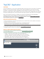
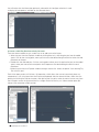
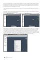
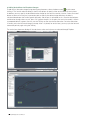
TrayCAD™ software
CTTCM-14
TrayCAD™ application
User manual
Table of Contents
TrayCAD™ Application ................................................................................................................................................................... 1
Overview ..................................................................................................................................................................................................... 1
Application Pre-Requisites........................................................................................................................................................... 1
How to use TrayCAD ................................................................................................................................................................ 1-13
Select Product Line ...................................................................................................................................................................... 2
Configuring Cable Tray Components ..................................................................................................................... 2-3
Create a Cable Tray Run Interactively Onscreen .......................................................................................... 3-4
Adding Bends, Tee’s, Crosses, Wyes or Reducers While Jigging ..................................................... 5
Adding Vertical Parts for Elevation Changes ........................................................................................................ 6
UNDO During Part Placement ............................................................................................................................................ 7
Adding Tee or Cross Parts Into Existing Straight Sections ...................................................................... 7
Alignment Snapping - Toggling ....................................................................................................................................... 8
Stop Jigging ...................................................................................................................................................................................... 8
Selecting a New Starting Point for Jigging ............................................................................................................ 8
Bill of Materials (BOM) Creation ................................................................................................................................. 8-9
Align Tray .......................................................................................................................................................................................... 10
Re-establish Run Connectivity ........................................................................................................................................ 11
Select Trays with Non-Standard Alignment Connections ..................................................................... 11
Displaying and Changing Properties ................................................................................................................ 12-13
Using Floor Plans to Create a Cable Tray Run ....................................................................................................... 14
Trouble Shooting ..................................................................................................................................................................... 14-15
TrayCAD Data Library is Empty or Invalid ........................................................................................................... 14
Missing Connection Points ................................................................................................................................................ 15
TrayCAD™ Application
OVERVIEW
The TrayCAD application is a custom software application add-in for AutoCAD (versions 2014 and 2015). The application
provides users with the ability to design a cable tray layout using the included library consisting of B-Line cable
tray products. The application will output a detailed bill of materials (BOM) for the cable tray system. This includes
quantities for straight sections, fittings, hold down clamps, covers and cover clamps, standard splice plates, expansion
splice plates (outdoor applications), and vertical/horizontal adjustable splice plates (when cable trays are non-aligned).
Note: All of the AutoCAD functionality is available to use, and the TrayCAD application has been developed to
complement AutoCAD’s features together with automating design of cable tray layouts.
For installation instructions, please see the document, TrayCAD Installation, located at: www.cooperbline.com/traycad.
For more information, please visit our website at: www.bline.com.
APPLICATION PRE-REQUISITES
•
•
•
The TrayCAD application has the following pre-requisites for use: AutoCAD 2014 or 2015 installed on the computer
Valid AutoCAD 2014 or 2015 license
Computer system must meet minimum requirements as specified for AutoCAD
For reference as to those system requirements, please visit the following site
http://knowledge.autodesk.com/support/autocad/troubleshooting/caas/sfdcarticles/sfdcarticles/System-requirements-for-AutoCAD.html
• Hardware acceleration turned ON within the AutoCAD OPTION or 3DCONFIG commands
• B-Line cable tray product data which can be found at www.cooperbline.com/traycad
• Available disk space to store the B-Line cable tray product data
HOW TO USE THE TRAYCAD APPLICATION
1. Install the B-Line cable tray product data (located at www.cooperbline.com/traycad)
2. Open AutoCAD 2014/2015
3. Select B-Line TrayCAD tab. Selecting the tab will display the following options:
• Explorer – Allows you to select the parts of the chosen product line
• Configure – Choice of B-Line cable tray product lines to use in your design
• BOM – Bill of Materials calculation for the cable tray layout you have created
• Non-Aligned – Select cable tray connections which are out of alignment.
• Network – provides the ability to re-establish connectivity in a cable tray run
1
TrayCAD Application User Manual
4. Select Product Line
To select a product line to use, please click on the Configure option from the B-Line TrayCAD™ tab.
If you have not downloaded any B-Line cable tray data, you will not receive any choices to select.
Please go to www.cooperbline.com/traycad to download the product data. Each product line needs
to be downloaded to make it available to the application.
The application will display the panel for you to make the selection of the products that will be required
for your design. Please select the Product Line first, and then enter the material, height, series
(if applicable) and width desired. The fittings and straight sections display will change according to your
selections. Click OK to select.
5. Configuring Cable Tray Components
To start the creation of the cable tray run, ensure you are using AutoCAD in MODEL space.
Click the B-Line TrayCAD add-on, and select the Explorer as shown below.
2
TrayCAD Application User Manual
You will notice that the information previously selected in the Configure selection is used
to display the components available for the selected values.
6. Create a Cable Tray Run Interactively Onscreen
There are three methods to start a cable tray run or add a part to the layout:
• Select the part from the Explorer window by clicking once on it, then drag the part into the model
space. Click for the starting point, move your mouse to the desired length and click to select the end
placement of the part.
• Double click the selected part. Click the starting point where you wish to place the part on the model
space, move your mouse to the end point which represents the desired length and click to end
placement.
• Select the part from the Explorer window and right mouse click. Select the option “Start drawing Tray
Run with this part”
Each of the above actions will initiate a ‘jig’ operation, which allows the user to interactively place tray
components in 3D, using input from the mouse and keyboard. After the above initiation, select the start
point by left-clicking the mouse onscreen. After picking the first point, move the mouse cursor away from
the initial point to see the jig extend the first straight section for the tray run. Select another point (left
mouse click) to end the straight section.
3
TrayCAD Application User Manual
Once you have placed your first straight section component, TrayCAD™ proposes horizontal bends (in green
by default) for several angles off of straight. The application will make the adjustment to place a bend part or
a straight part, as the case may be. Once you have the length or angle needed for the part, left mouse click
to end the placement of the endpoint of the fitting.
Note: the elevation (Z value) of the tray place with the jig is set using the AutoCAD ELEVATION command/
SYSVAR.
For example, place a straight section and then move the mouse up or straight, to specify different horizontal
bend fittings based upon the selected angle.
Depending on the selected tray library, each horizontal bend fitting has an option for radius that is selectable
using the TAB key while the proposed bend part is visible. Press the TAB key to cycle through the available
radius options for a given bend part (the proposed bend part will visibly change to indicate your selection).
In addition, by right mouse selection of an existing part you have the ability to “TrayCAD: Place more like this”
which will copy the part settings for you to place additional parts in the model. Select this option on a straight
section, or a fitting that is attached to a straight section to begin placement of a similar part.
4
TrayCAD Application User Manual
7. Adding Bend, Tee’s, Crosses, Wyes or Reducers While Jigging
During part placement, a small, semi-transparent context dialog
follows the jig points.
This dialog is used to specify additional horizontal and vertical parts not proposed by the standard
onscreen jig. The
button is used to specify additional horizontal parts, while the
allow you to specify vertical parts (see the next section below).
button will
To add a horizontal bend, tee, cross, wye or reducer fitting during jigging, select the plus sign
by left mouse clicking it. The panel with the selection of fittings available will be displayed. Specify
the part type with the radio buttons on the left, then use the ‘up’ and ‘down’ buttons to cycle
through to the desired part. Once the part is selected, hit ‘OK’ to place the part onscreen at the
jig’s current location. At this point the part is still proposed (in green). You may use the TAB key to
alter the orientation of the part. Once the orientation is set, left click the mouse to accept the part
and continue jigging. For tee and cross fittings chosen this way, use the TAB key again to specify
the location to continue jigging. The TAB key will cycle through the available connection points for
jigging going forward.
In this example, a bend was selected. Using the TAB key will cycle the orientation of the proposed bend.
Pressing left mouse will accept it; pressing escape will cancel.
5
TrayCAD Application User Manual
8. Adding Vertical Parts for Elevation Changes
To add vertical, elevation change fittings during part placement, select the down arrow
by left mouse
clicking it. The vertical selection dialog is shown with options to specify either vertical bends or vertical tees.
In addition, you may specify the desired elevation change for the vertical assembly. Use the “Select Onscreen”
button to select an existing tray’s connection point to specify the desired target elevation; the delta is
calculated based upon the current jig point elevation, and the part is refactored to suit. Once the desired parts
and elevation change values are set, press ‘OK’ to place the part. At this point, the vertical assembly is shown
as proposed (default in green). You may use the TAB key to alter the relative orientation. Once the orientation
is correct, press the left mouse button to accept. After it is placed, for vertical tees, you may cycle the forward
connection point by again using the TAB key.
The vertical part placement dialog will also be shown when vertical parts are selected through Explorer.
6
TrayCAD Application User Manual
9. UNDO During Part Placement
At any point during part placement using the jig, you may UNDO the last part placed by using the
‘U’ option on the keyboard (or the context menu via right mouse click). Issuing this will remove the
last-placed part in the jig. UNDO may be issued all the way back to the first part placed, at which
point the command will terminate.
10. Adding Tee or Cross parts into existing Straight Sections
You may interrupt straight sections with tee or cross fittings by right mouse clicking a given straight
section and choosing the “TrayCAD Tee/X into existing straight section and Jig” selection. This
option allows you to enter a tee or cross along the straight section by moving your mouse to the
desired placement location.
When initiating this action, the horizontal selection dialog will prompt you to select the desired
tee or cross part. Once selected, the jig will display the proposed part and allow lateral placement
within the straight section using the mouse. At this point, you may also use the TAB key to alter the
orientation of the part.
Once placed, you may use the TAB key again to select the forward jig point (for crosses only, as the tee will only
have a single available point going forward). Continue jigging from the forward connection point as normal.
7
TrayCAD Application User Manual
11. Alignment Snapping – Toggling
By default, TrayCAD™ will attempt to snap to the previous tray’s alignment – to within 10 degrees. If finer
control of the alignment is required, and this default snapping is not desired, you may toggle it off by hitting
the CTRL key once. Hit the CTRL key again to turn snapping back on.
12. Stop Jigging
To discontinue or exit out of the “jigging” mode, just press ESC.
13. Selecting a New Starting Point for Jigging
To select another point to start jigging, just select one of the components you wish to attach by either of the following methods:
• Double clicking the fitting and select the connection point (shown in yellow in the figure below)
• Drag and drop as described above to one of the connection points (shown in yellow in the figure below)
• Right click from the selected fitting and select
14. Bill of Materials (BOM) Creation
The TrayCAD application has the ability to provide the BOM for the cable tray run you are working on.
To create the BOM, select the BOM option from the B-Line TrayCAD tab.
8
TrayCAD Application User Manual
The application will give you the following selection:
• Select All Cable Tray Objects in model
• Select Individual Cable Tray Objects
• Select a Cable Tray Run
Once you have made your selection, the application will make the calculations and display the BOM.
When you click Continue, the application will create a CSV export of the BOM.
Select the computer path where you want to place the CSV file of the BOM.
9
TrayCAD Application User Manual
15. Align Tray
It is possible to align a given fitting to an adjacent one when the two are conjoined by a common straight section.
To align trays, select the fitting to align then right-click and select the “TrayCAD: Align Tray” context menu option.
TrayCAD™ prompts to select an alignment point. Select the far end point of straight section which is connected
to the selected fitting; the selected fitting is aligned to the fitting at that far end.
Note: If selected connection point is not at the far end of a connected straight section or a fitting is not connected
there, you will receive a warning that there is no solution.
10
TrayCAD Application User Manual
16. Re-establish Run Connectivity
TrayCAD™ will attempt to maintain network connectivity for connected trays as much as possible.
Connection points which are connected will show a green connection circle, while broken
connection points will show a yellow connection circle.
There are complex operations which may interrupt TrayCAD application’s ability to maintain this
network synchronization, and monitoring every possible operation which does this would impact
performance severely. As an alternative, you may run the NETWORK command to manually
re-establish the network connectivity, should synchronization be lost.
To re-establish run connectivity, select the Network option from the B-Line TrayCAD tab.
17. Select Trays with Non-Standard Alignment Connections
It is possible to check what tray sections within the layout have non-standard aligned connections
by selecting the “Non-Aligned” option in the ribbon tab.
When selecting this option, the cable tray sections that have connections that are off axis will
highlight showing what runs and/or fittings will require the need for a pair of vertical or horizontal
adjustable splice plates (depending on the cable tray orientation). To exclude or minimize the
quantity of adjustable splice plates within the BOM, cable tray segments that are highlighted as
being “non-aligned” will need to be aligned. See “Align Tray” section on page 10.
11
TrayCAD Application User Manual
18. Displaying and Changing Properties
There are two different ways to gather properties for the TrayCAD™ parts. One of the properties dialog
is part of the TrayCAD application that lets you view part properties. The AutoCAD properties dialog will
give you the ability to change properties of a part.
Note: It is important to understand that one dialog is part of the AutoCAD software and the other
dialog is part of the TrayCAD application plug-in.
Select an object in your tray run, and then initiate the context menu in your drawing editor.
Then select the TrayCAD Part Properties option. This will start a new dialog box with all the properties
of that run. Keep in mind that this is a viewer for the properties and not an editable dialog.
12
TrayCAD Application User Manual
Another option for part properties will be the AutoCAD properties dialog or “Properties Palette”, which
will give you options to change part information and type. Select the part you need to find properties and
initiate the context menu by right clicking in the drawing editor and select the option for “Properties”, only
at the bottom.
Once selected, you will see the standard properties palette appear.
In this dialog, you will see the category for the “Cable Tray Properties”.
In this properties palette, you can change the following properties:
• Height - Allows user to select various side rail heights that are available
• Knockout Type - Allows user to select various conduit knockout sizes that are available (Redi-Rail™ cable tray system ONLY)
• Bottom Type - Allows user to select various bottom types that are available
• Width - Allows user to select various widths that are available
• Length - Allows user to select various straight section lengths that are available
• Indoor/Outdoor - Allows user to determine whether expansion
splices and bonding jumpers are to be added into the Bill of Materials. Quantity of expansion splices and bonding jumpers are based
on selected cable tray material and temperature differential. Temperature differential is assumed to be 100ºF (38ºC). Please see the latest B-Line Cable Tray catalog “Cable Tray Section” for more information.
• Cover Type - Allows user to select various types of cover configurations that are available 13
TrayCAD Application User Manual
USING FLOOR PLANS TO CREATE A CABLE TRAY RUN
The TrayCAD™ application allows you to open an AutoCAD file to use as a layout guide.
You could use a 2D architectural floor plan to start the layout and jigging process. The only caveat is to
account for the z-axis elevation of parts in the area you are working in the drawing. Ideally, you would
xreference a 3D floorplan into the drawing editor as a guide for the TrayCAD layout.
Note: See AutoCAD help menu for how to create an XREF.
TROUBLE SHOOTING
1. TrayCAD Data Library is Empty or Invalid
You will receive this error if no TrayCAD™ product data has been downloaded or it has become
corrupt. Please go to www.cooperbline.com/traycad to get the data installation instructions and
download the latest product data.
14
TrayCAD Application User Manual
2. Missing Connection Points
Using a few AutoCAD commands like copy/array which will make cable tray parts to lose x-data/connection
points. Select the parts with the missing connection points and from the B-Line TrayCAD™ selection, click
on Network.
If you have questions or would like to know more about B-Line’s TrayCAD software, please
contact B-Line customer service at (800)-851-7415 and ask to speak with a sales engineer.
NOTICE
B-Line reserves the right to change the specifications, materials, equipment, prices or the availability
of products at any time without prior notice. While every effort has been made to assure the accuracy
of information contained in this catalog at the time of publication, B-Line is not responsible for
inaccuracies resulting from undetected errors or omissions.
15
TrayCAD Application User Manual
Copyright © 2012 Autodesk, Inc.
All Rights Reserved
This publication, or parts thereof, may not be reproduced in any form, by any method, for any purpose. AUTODESK, INC., MAKES
NO WARRANTY, EITHER PERKINS + WILLRESS OR IMPLIED, INCLUDING BUT NOT LIMITED TO ANY IMPLIED WARRANTIES OF
MERCHANTABILITY OR FITNESS FOR A PARTICULAR PURPOSE REGARDING THESE MATERIALS, AND MAKES SUCH MATERIALS
AVAILABLE SOLELY ON AN “AS-IS” BASIS. IN NO EVENT SHALL AUTODESK, INC. BE LIABLE TO ANYONE FOR SPECIAL,
COLLATERAL, INCIDENTAL, OR CONSEQUENTIAL DAMAGES IN CONNECTION WITH OR ARISING OUT OF PURCHASE OR USE OF
THESE MATERIALS. THE SOLE AND EXCLUSIVE LIABILITY TO AUTODESK, INC., REGARDLESS OF THE FORM OF ACTION, SHALL
NOT EXCEED THE PURCHASE PRICE OF THE MATERIALS DESCRIBED HEREIN.
Autodesk, Inc., reserves the right to revise and improve its products as it sees fit. This publication describes the state of this product at
the time of its publication, and may not reflect the product at all times in the future.
Autodesk Trademarks
The following are registered trademarks of Autodesk, Inc., in the USA and/or other countries: 3D Props, 3D Studio, 3D Studio MAX, 3D
Studio VIZ, 3DSurfer, Active Shapes, Active Shapes (logo), Actrix, ADI, AEC Authority (logo), AEC-X, Animator Pro, Animator Studio, ATC,
AUGI, AutoCAD, AutoCAD LT, AutoCAD Map, Autodesk, Autodesk Inventor, Autodesk (logo), Autodesk MapGuide, Autodesk University
(logo), Autodesk View, Autodesk WalkThrough, Autodesk World, AutoLISP, AutoSketch, Biped, bringing information down to earth, CAD
Overlay, Character Studio, Cinepak, Cinepak (logo), Codec Central, Combustion, Design Your World, Design Your World (logo), Discreet,
EditDV, Education by Design, gmax, Heidi, HOOPS, Hyperwire, i-drop, Inside Track, Kinetix, MaterialSpec, Mechanical Desktop, NAAUG,
ObjectARX, PeopleTracker, Physique, Planix, Powered with Autodesk Technology (logo), RadioRay, Revit, Softdesk, Texture Universe, The
AEC Authority, The Auto Architect, VISION, Visual, Visual Construction, Visual Drainage, Visual Hydro, Visual Landscape, Visual Roads,
Visual Survey, Visual Toolbox, Visual TugBoat, Visual LISP, Volo, WHIP!, and WHIP! (logo). The following are trademarks of Autodesk,
Inc., in the USA and/or other countries: 3ds max, AutoCAD Architectural Desktop, AutoCAD Learning Assistance, AutoCAD LT Learning
Assistance, AutoCAD Simulator, AutoCAD SQL Extension, AutoCAD SQL Interface, Autodesk Map, Autodesk Streamline, AutoSnap,
AutoTrack, Built with ObjectARX (logo), Burn, Buzzsaw, Buzzsaw.com, Cinestream, Cleaner, Cleaner Central, ClearScale, Colour Warper,
Content PERKINS + WILLlorer, Dancing Baby (image), DesignCenter, Design Doctor, Designer’s Toolkit, DesignProf, DesignServer,
Design Web Format, DWF, DWG Linking, DXF, Extending the Design Team,GDX Driver, gmax (logo), gmax ready (logo),Heads-up Design,
IntroDV, jobnet, ObjectDBX, onscreen onair online, Plans & Specs, Plasma, PolarSnap, ProjectPoint, Reactor, Real-time Roto, Render
Queue, Visual Bridge, Visual Syllabus, and Where Design Connects.
Autodesk Canada Inc. Trademarks
The following are registered trademarks of Autodesk Canada Inc. in the USA and/or Canada, and/or other countries: discreet, fire, flame,
flint, flint RT, frost, glass, inferno, MountStone, riot, river, smoke, sparks, stone, stream, vapour, wire. The following are trademarks of
Autodesk Canada Inc., in the USA, Canada, and/or other countries: backburner, backdraft, Multi-Master Editing.
Third Party Trademarks
All other brand names, product names or trademarks belong to their respective holders.
Third Party Software Program Credits
ACIS Copyright © 1989-2001 Spatial Corp. Portions Copyright © 2002 Autodesk, Inc.
Copyright © 1997 Microsoft Corporation. All rights reserved. Copyright (c) 2003 GlobalCAD Consultants Ltd. Hatch Manager and
Linetype Wizard are trademarks of GlobalCAD Consultants Ltd. All rights reserved.
International CorrectSpell™ Spelling Correction System © 1995 by Lernout & Hauspie Speech Products, N.V. All rights reserved.
InstallShield™ 3.0. Copyright © 1997 InstallShield Software Corporation. All rights reserved.
PANTONE ® Colors displayed in the software application or in the user documentation may not match PANTONE-identified standards.
Consult current PANTONE Color Publications for accurate color.
PANTONE ® and other Pantone, Inc. trademarks are the property of Pantone, Inc. © Pantone, Inc., 2002
Pantone, Inc. is the copyright owner of color data and/or software which are licensed to Autodesk, Inc., to distribute for use only in
combination with certain Autodesk software products. PANTONE Color Data and/or Software shall not be copied onto another disk or
into memory unless as part of the execution of this Autodesk software product.
Portions Copyright © 1991-1996 Arthur D. Applegate. All rights reserved. Portions of this software are based on the work of the
Independent JPEG Group. RAL DESIGN © RAL, Sankt Augustin, 2002
RAL CLASSIC © RAL, Sankt Augustin, 2002
Representation of the RAL Colors is done with the approval of RAL Deutsches Institut für Gütesicherung und Kennzeichnung e.V. (RAL
German Institute for Quality Assurance and Certification, re. Assoc.), D-53757 Sankt Augustin.”
Typefaces from the Bitstream ® typeface library copyright 1992. Typefaces from Payne Loving Trust © 1996. All rights reserved.
GOVERNMENT USE
Use, duplication, or disclosure by the U.S. Government is subject to restrictions as set forth in FAR 12.212 (Commercial Computer
Software- Restricted Rights) and DFAR 227.7202 (Rights in Technical Data and Computer Software), as applicable.
Eaton’s B-Line Business
United States
509 West Monroe Street
Highland, IL 62249
United States
Phone: 800-851-7415
www.cooperbline.com/contactus
Eaton’s B-Line Business
Canada
5925 McLaughlin Road
Mississauga, ON L5R 1B8
Canada
Phone: 800-569-3660
www.cooperbline.com/contactca
Eaton’s Cooper Singapore
No. 2 Serangoon North Ave. 5
#06-01 Fu Yu Building, 554911
Singapore
Phone: +65 (0) 62974849
Eaton’s Cooper Korea Co., Ltd.
13 Fl Vision Tower, 7072 Yeoksam-dong
Gangnam-gu
Seoul, 135-080
Korea
Phone: +44 (0) 1278 772600
Eaton
1000 Eaton Boulevard
Cleveland, OH 44122
United States
Eaton.com
Eaton’s B-Line Business
509 West Monroe Street
Highland, IL 62249
Eaton.com
© 2014 Eaton
All Rights Reserved
Printed in USA
Publication No. CTTCM-14
November 2014
Eaton is a registered trademark.
All other trademarks are property
of their respective owners.
Eaton’s B-Line Business
Saudi Arabia
PO Box 70160 - Al Khobar - 31952
Kingdom of Saudi Arabia
Phone: 00966 3 812 2236
www.cooperbline.com/contactme