1
User’s Manual
CubeSuite+ V1.00.00
Integrated Development Environment
User’s Manual: V850 Coding
Target Device
V850 Microcontroller
All information contained in these materials, including products and product specifications,
represents information on the product at the time of publication and is subject to change by
Renesas Electronics Corp. without notice. Please review the latest information published by
Renesas Electronics Corp. through various means, including the Renesas Electronics Corp.
website (http://www.renesas.com).
www.renesas.com
Rev.1.00
Apr 2011
Notice
1.
2.
3.
4.
5.
6.
7.
All information included in this document is current as of the date this document is issued. Such information, however, is
subject to change without any prior notice. Before purchasing or using any Renesas Electronics products listed herein, please
confirm the latest product information with a Renesas Electronics sales office. Also, please pay regular and careful attention to
additional and different information to be disclosed by Renesas Electronics such as that disclosed through our website.
Renesas Electronics does not assume any liability for infringement of patents, copyrights, or other intellectual property rights
of third parties by or arising from the use of Renesas Electronics products or technical information described in this document.
No license, express, implied or otherwise, is granted hereby under any patents, copyrights or other intellectual property rights
of Renesas Electronics or others.
You should not alter, modify, copy, or otherwise misappropriate any Renesas Electronics product, whether in whole or in part.
Descriptions of circuits, software and other related information in this document are provided only to illustrate the operation of
semiconductor products and application examples. You are fully responsible for the incorporation of these circuits, software,
and information in the design of your equipment. Renesas Electronics assumes no responsibility for any losses incurred by
you or third parties arising from the use of these circuits, software, or information.
When exporting the products or technology described in this document, you should comply with the applicable export control
laws and regulations and follow the procedures required by such laws and regulations. You should not use Renesas
Electronics products or the technology described in this document for any purpose relating to military applications or use by
the military, including but not limited to the development of weapons of mass destruction. Renesas Electronics products and
technology may not be used for or incorporated into any products or systems whose manufacture, use, or sale is prohibited
under any applicable domestic or foreign laws or regulations.
Renesas Electronics has used reasonable care in preparing the information included in this document, but Renesas Electronics
does not warrant that such information is error free. Renesas Electronics assumes no liability whatsoever for any damages
incurred by you resulting from errors in or omissions from the information included herein.
Renesas Electronics products are classified according to the following three quality grades: “Standard”, “High Quality”, and
“Specific”. The recommended applications for each Renesas Electronics product depends on the product’s quality grade, as
indicated below. You must check the quality grade of each Renesas Electronics product before using it in a particular
application. You may not use any Renesas Electronics product for any application categorized as “Specific” without the prior
written consent of Renesas Electronics. Further, you may not use any Renesas Electronics product for any application for
which it is not intended without the prior written consent of Renesas Electronics. Renesas Electronics shall not be in any way
liable for any damages or losses incurred by you or third parties arising from the use of any Renesas Electronics product for an
application categorized as “Specific” or for which the product is not intended where you have failed to obtain the prior written
consent of Renesas Electronics. The quality grade of each Renesas Electronics product is “Standard” unless otherwise
expressly specified in a Renesas Electronics data sheets or data books, etc.
“Standard”:
8.
9.
10.
11.
12.
Computers; office equipment; communications equipment; test and measurement equipment; audio and visual
equipment; home electronic appliances; machine tools; personal electronic equipment; and industrial robots.
“High Quality”: Transportation equipment (automobiles, trains, ships, etc.); traffic control systems; anti-disaster systems; anticrime systems; safety equipment; and medical equipment not specifically designed for life support.
“Specific”:
Aircraft; aerospace equipment; submersible repeaters; nuclear reactor control systems; medical equipment or
systems for life support (e.g. artificial life support devices or systems), surgical implantations, or healthcare
intervention (e.g. excision, etc.), and any other applications or purposes that pose a direct threat to human life.
You should use the Renesas Electronics products described in this document within the range specified by Renesas Electronics,
especially with respect to the maximum rating, operating supply voltage range, movement power voltage range, heat radiation
characteristics, installation and other product characteristics. Renesas Electronics shall have no liability for malfunctions or
damages arising out of the use of Renesas Electronics products beyond such specified ranges.
Although Renesas Electronics endeavors to improve the quality and reliability of its products, semiconductor products have
specific characteristics such as the occurrence of failure at a certain rate and malfunctions under certain use conditions. Further,
Renesas Electronics products are not subject to radiation resistance design. Please be sure to implement safety measures to
guard them against the possibility of physical injury, and injury or damage caused by fire in the event of the failure of a
Renesas Electronics product, such as safety design for hardware and software including but not limited to redundancy, fire
control and malfunction prevention, appropriate treatment for aging degradation or any other appropriate measures. Because
the evaluation of microcomputer software alone is very difficult, please evaluate the safety of the final products or system
manufactured by you.
Please contact a Renesas Electronics sales office for details as to environmental matters such as the environmental
compatibility of each Renesas Electronics product. Please use Renesas Electronics products in compliance with all applicable
laws and regulations that regulate the inclusion or use of controlled substances, including without limitation, the EU RoHS
Directive. Renesas Electronics assumes no liability for damages or losses occurring as a result of your noncompliance with
applicable laws and regulations.
This document may not be reproduced or duplicated, in any form, in whole or in part, without prior written consent of Renesas
Electronics.
Please contact a Renesas Electronics sales office if you have any questions regarding the information contained in this
document or Renesas Electronics products, or if you have any other inquiries.
(Note 1) “Renesas Electronics” as used in this document means Renesas Electronics Corporation and also includes its majorityowned subsidiaries.
(Note 2) “Renesas Electronics product(s)” means any product developed or manufactured by or for Renesas Electronics.
How to Use This Manual
This manual describes the role of the CubeSuite+ integrated development environment for developing application
systems for V850 microcontrollers, and provides an outline of its features.
CubeSuite+ is an integrated development environment (IDE) for V850 microcontrollers, integrating the necessary
tools for the development phase of software (e.g. design, implementation, and debugging) into a single platform.
By providing an integrated environment, it is possible to perform all development using just this product, without
the need to use many different tools separately.
Readers
This manual is intended for users who wish to understand the functions of the
CubeSuite+ and design software and hardware application systems.
Purpose
This manual is intended to give users an understanding of the functions of the
CubeSuite+ to use for reference in developing the hardware or software of systems
using these devices.
Organization
This manual can be broadly divided into the following units.
CHAPTER 1 GENERAL
CHAPTER 2 FUNCTIONS
CHAPTER 3 COMPILER LANGUAGE SPECIFICATIONS
CHAPTER 4 ASSEMBLY LANGUAGE SPECIFICATIONS
CHAPTER 5 LINK DIRECTIVE SPECIFICATION
CHAPTER 6 FUNCTIONAL SPECIFICATION
CHAPTER 7 STARTUP
CHAPTER 8 ROMIZATION
CHAPTER 9 REFERENCING COMPILER AND ASSEMBLER
CHAPTER 10 CAUTIONS
APPENDIX A EDITOR
APPENDIX B INDEX
How to Read This Manual It is assumed that the readers of this manual have general knowledge of electricity, logic
circuits, and microcontrollers.
Conventions
Data significance:
Higher digits on the left and lower digits on the right
–––
Active low representation: XXX (overscore over pin or signal name)
Note:
Footnote for item marked with Note in the text
Caution:
Information requiring particular attention
Remark:
Supplementary information
Numeric representation:
Decimal … XXXX
Hexadecimal … 0xXXXX
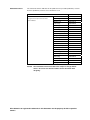
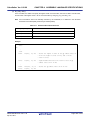
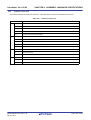
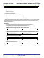
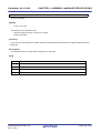
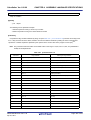
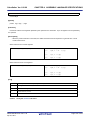
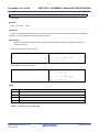
Related Documents
The related documents indicated in this publication may include preliminary versions.
However, preliminary versions are not marked as such.
Document Name
Document No.
CubeSuite+
Start
R20UT0545E
Integrated Development Environment
78K0 Design
R20UT0546E
User's Manual
78K0R Design
R20UT0547E
Caution
RL78 Design
R20UT0548E
V850 Design
R20UT0549E
R8C Design
R20UT0550E
78K0 Coding
R20UT0551E
RL78,78K0R Coding
R20UT0552E
V850 Coding
This manual
Coding for CX Compiler
R20UT0554E
R8C Coding
R20UT0576E
78K0 Build
R20UT0555E
RL78,78K0R Build
R20UT0556E
V850 Build
R20UT0557E
Build for CX Compiler
R20UT0558E
R8C Build
R20UT0575E
78K0 Debug
R20UT0559E
78K0R Debug
R20UT0560E
RL78 Debug
R20UT0561E
V850 Debug
R20UT0562E
R8C Debug
R20UT0574E
Analysis
R20UT0563E
Message
R20UT0407E
The related documents listed above are subject to change without
notice. Be sure to use the latest edition of each document when
designing.
All trademarks or registered trademarks in this document are the property of their respective
owners.
[MEMO]
[MEMO]
[MEMO]
TABLE OF CONTENTS
CHAPTER 1 GENERAL ... 13
1.1 Outline ... 13
1.2 Special Features ... 13
CHAPTER 2 FUNCTIONS ... 14
2.1 Variables (C language) ... 14
2.1.1 Allocating to sections accessible with short instructions ... 14
2.1.2 Changing allocated section ... 15
2.1.3 Defining variables for use during standard and interrupt processing ... 17
2.1.4 Defining user port ... 19
2.1.5 Defining const constant pointer ... 20
2.2 Functions ... 21
2.2.1 Changing area to be allocated to ... 21
2.2.2 Calling an away function ... 22
2.2.3 Embedding assembler instructions ... 23
2.2.4 Executing in RAM ... 23
2.3 Using Microcomputer Functions ... 24
2.3.1 Accessing peripheral I/O register with C language ... 24
2.3.2 Describing interrupt processing with C language ... 25
2.3.3 Using CPU instructions in C language ... 26
2.3.4 Creating a self-programming boot area ... 28
2.4 Variables (Assembler) ... 29
2.4.1 Defining variables with no initial values ... 29
2.4.2 Defining const constants with initial values ... 30
2.4.3 Referencing section addresses ... 31
2.5 Startup Routine ... 32
2.5.1 Secure stack area ... 32
2.5.2 Securing stack area and specifying allocation ... 34
2.5.3 Initializing RAM ... 35
2.5.4 Preparing function and variable access ... 36
2.5.5 Preparing to use code size reduction function ... 39
2.5.6 Ending startup routine ... 40
2.6 Link Directives ... 41
2.6.1 Adding function section allocation ... 41
2.6.2 Adding section allocation for variables ... 41
2.6.3 Distributing section allocation ... 42
2.7 Reducing Code size ... 44
2.7.1 Reducing code size (C language) ... 44
2.7.2 Reducing variable area with variable definition method ... 56
2.8 Accelerating Processing ... 59
2.8.1 Accelerate processing with description method ... 59
2.9 Compiler and Assembler Mutual References ... 61
2.9.1 Mutually referencing variables ... 61
2.9.2 Mutually referencing functions ... 63
CHAPTER 3 COMPILER LANGUAGE SPECIFICATIONS ... 64
3.1 Basic Language Specifications ... 64
3.1.1 Processing system dependent Items ... 64
3.1.2 Ansi option ... 77
3.1.3 Internal representation and value area of data ... 78
3.1.4 General-purpose registers ... 84
3.1.5 Referencing data ... 85
3.1.6 Software register bank ... 85
3.1.7 Mask register ... 87
3.1.8 Device file ... 89
3.2 Extended Language Specifications ... 91
3.2.1 Macro name ... 91
3.2.2 Keyword ... 92
3.2.3 #pragma directive ... 92
3.2.4 Using expanded specifications ... 94
3.2.5 Modification of C-source ... 148
3.3 Function Call Interface ... 149
3.3.1 Calling between C functions ... 149
3.3.2 Prologue/Epilogue processing function ... 160
3.3.3 far jump function ... 162
3.4 Expanded Function of CC78Kx ... 168
3.4.1 #pragma directive ... 168
3.4.2 Assembler control instructions ... 172
3.4.3 Specifying interrupt/exception handler ... 172
3.4.4 Expanded function not supported ... 172
3.5 Section Name List ... 172
CHAPTER 4 ASSEMBLY LANGUAGE SPECIFICATIONS ... 174
4.1 Description of Source ... 174
4.1.1 Description ... 174
4.1.2 Expression ... 183
4.1.3 Operators ... 185
4.1.4 Arithmetic operators ... 186
4.1.5 Shift operators ... 186
4.1.6 Bitwise logical operators ... 187
4.1.7 Comparison operators ... 187
4.1.8 Operation rules ... 189
4.1.9 Definition of absolute expression ... 190
4.1.10 Identifiers ... 192
4.1.11 Characteristics of an operand ... 192
4.2 Quasi Directives ... 207
4.2.1 Outline ... 207
4.2.2 Section definition quasi directives ... 208
4.2.3 Symbol control quasi directives ... 232
4.2.4 Location counter control quasi directives ... 239
4.2.5 Area allocation quasi directives ... 242
4.2.6 Program linkage quasi directives ... 251
4.2.7 Assembler control quasi directive ... 257
4.2.8 File input control quasi directives ... 262
4.2.9 Repetitive assembly quasi directives ... 265
4.2.10 Conditional assembly quasi directives ... 269
4.2.11 Skip quasi directives ... 283
4.2.12 Macro quasi directives ... 288
4.3 Macro ... 293
4.3.1 Outline ... 293
4.3.2 Usage of macro ... 294
4.3.3 Symbols in macro ... 294
4.3.4 Macro operator ... 295
4.4 Reserved Words ... 296
4.5 Instructions ... 297
4.5.1 Memory space ... 297
4.5.2 Register ... 298
4.5.3 Addressing ... 334
4.5.4 Instruction set ... 342
4.5.5 Description of instructions ... 357
4.5.6 Load/Store instructions ... 358
4.5.7 Arithmetic operation instructions ... 367
4.5.8 Saturated operation instructions ... 430
4.5.9 Logical instructions ... 444
4.5.10 Branch instructions ... 490
4.5.11 Bit Manipulation instructions ... 507
4.5.12 Stack manipulation instructions ... 516
4.5.13 Special instructions ... 521
4.5.14 Pipeline (V850) ... 545
4.5.15 Pipeline (V850ES) ... 569
4.5.16 Pipeline (V850E1) ... 609
4.5.17 Pipeline (V850E2) ... 647
CHAPTER 5 LINK DIRECTIVE SPECIFICATION ... 679
5.1 Coding Method ... 679
5.1.1 Characters used in link directive file ... 679
5.1.2 Link directive file name ... 680
5.1.3 Segment directive ... 680
5.1.4 Mapping directive ... 685
5.1.5 Symbol directive ... 692
5.2 Reserved Words ... 697
CHAPTER 6 FUNCTIONAL SPECIFICATION ... 698
6.1 Supplied Libraries ... 698
6.1.1 Standard library ... 700
6.2
6.3
6.4
6.5
6.6
6.1.2 Mathematical library ... 705
6.1.3 ROMization library ... 707
Header Files ... 708
Re-entrant ... 708
Library Function ... 709
6.4.1 Functions with variable arguments ... 709
6.4.2 Character string functions ... 713
6.4.3 Memory management functions ... 731
6.4.4 Character conversion functions ... 739
6.4.5 Character classification functions ... 745
6.4.6 Standard I/O functions ... 758
6.4.7 Standard utility functions ... 790
6.4.8 Non-local jump functions ... 817
6.4.9 Mathematical functions ... 820
6.4.10 Copy function ... 861
Runtime Library ... 862
Library Consumption Stack List ... 864
6.6.1 Standard library ... 864
6.6.2 Mathematical library ... 874
6.6.3 ROMization library ... 875
CHAPTER 7 STARTUP ... 876
7.1 Functional Outline ... 876
7.2 File Contents ... 876
7.3 Startup Routine ... 877
7.3.1 Setting RESET handler when reset is input ... 878
7.3.2 Setting of register mode of start up routine ... 878
7.3.3 Securing stack area and setting stack pointer ... 879
7.3.4 Securing argument area for main function ... 880
7.3.5 Setting text pointer (tp) ... 880
7.3.6 Setting global pointer (gp) ... 881
7.3.7 Setting element pointer (ep) ... 882
7.3.8 Setting mask value to mask registers (r20 and r21) ... 882
7.3.9 Initializing peripheral I/O registers that must be initialized before execution of main
function ... 883
7.3.10 Initializing user target that must be initialized before execution of main function ... 884
7.3.11 Clearing sbss area to 0 ... 884
7.3.12 Clearing bss area to 0 ... 885
7.3.13 Clearing sebss area to 0 ... 886
7.3.14 Clearing tibss.byte area to 0 ... 887
7.3.15 Clearing tibss.word area to 0 ... 888
7.3.16 Clearing sibss area to 0 ... 889
7.3.17 Setting of CTBP value for prologue/epilogue runtime library of functions [V850E] ...
890
7.3.18 Setting of programmable peripheral I/O register value [V850E] ... 891
7.3.19 Setting r6 and r7 as argument of main function ... 892
7.3.20 Branching to main function (when not using real-time OS) ... 892
7.3.21 Branching to initialization routine of real-time OS (when using real-time OS) ... 893
7.4 Coding Example ... 894
CHAPTER 8 ROMIZATION ... 900
8.1 Outline ... 900
8.2 rompsec Section ... 902
8.2.1 Types of sections to be packed ... 902
8.2.2 Size of rompsec section ... 902
8.2.3 rompsec section and link directive ... 903
8.3 Creation of Object for ROMization ... 905
8.3.1 Creation procedure (default) ... 905
8.3.2 Creation procedure (customize) ... 907
8.4 Copy Function ... 910
CHAPTER 9 REFERENCING COMPILER AND ASSEMBLER ... 915
9.1
9.2
9.3
9.4
9.5
Method of Accessing Arguments and Automatic Variables ... 915
Method of Storing Return Value ... 915
Calling of Assembly Language Routine from C Language ... 916
Calling of C Language Routine from Assembly Language ... 917
Reference of Argument Defined by Other Language ... 918
CHAPTER 10 CAUTIONS ... 919
10.1 Delimiting Folder/Path ... 919
10.2 Option Specification Sequence ... 919
10.3 Mixing with K&R Format in Function Declaration/Definition ... 920
10.4 Output of Other Than Position-Independent Codes ... 921
10.5 Count of Derivative Type Qualification for Type Configuration ... 921
10.6 Length of Identifier and Valid Number of Characters ... 921
10.7 Number of Times of Block Nesting ... 922
10.8 Number of case Labels in switch Statement ... 922
10.9 Floating-Point Operation Exception in Operation of Constant Expression ... 922
10.10 Merging Vast/Large-Quantity File ... 922
10.11 Optimization of Vast File ... 922
10.12 Library File Search by Specifying Option ... 923
10.13 Volatile Qualifier ... 923
10.14 Extra Brackets in Function Declaration ... 926
APPENDIX A EDITOR ... 927
APPENDIX B INDEX ... 932
CubeSuite+ Ver.1.00.00
CHAPTER 1 GENERAL
CHAPTER 1 GENERAL
This chapter provides a general outline of the V850 microcontrollers C compiler package(CA850).
1.1
Outline
The V850 microcontrollers C compiler package (CA850) is a program that converts programs described in C language
or assembly language into machine language.
1.2
Special Features
The V850 microcontrollers C compiler package is equipped with the following special features.
(1) Language specifications in accordance with ANSI standard
The C language specifications conform to the ANSI standard. Coexistence with prior C language specifications
(K&R specifications) is also provided.
(2) Advanced optimization
Code size and speed priority optimization for the C compiler and assembler are offered.
(3) Built-in control functionality
Utilites to facilitate application system ROMization work are offered.
(4) Improvement to description ability
C language programming description ability has been improved due to enhanced language specifications.
R20UT0553EJ0100 Rev.1.00
Apr 01, 2011
Page 13 of 943
CubeSuite+ Ver.1.00.00
CHAPTER 2 FUNCTIONS
CHAPTER 2 FUNCTIONS
This chapter explains the programming method and how to use the expansion functions for more efficient use of the
CA850.
2.1
Variables (C language)
This section explains variables (C language).
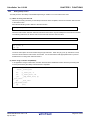
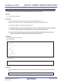
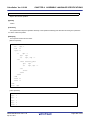
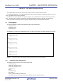
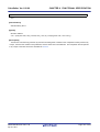
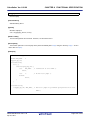
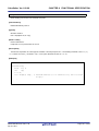
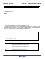
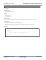
2.1.1
Allocating to sections accessible with short instructions
The V850 contains 2-byte instruction length load/store instructions. By allocating variables to sections accessible with
these instructions it is possible to reduce the code size.
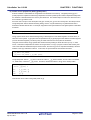
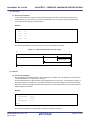
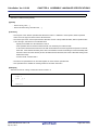
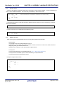
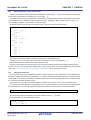
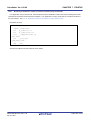
When defining or referencing a variable use the #pragma section and specify "tidata" as the section type.
#pragma section section-type begin
variable-declaration/definition
#pragma section section-type end
Example
#pragma section tidata begin
int a = 1;
/*allocated to tidata.word attribute section*/
int b;
/*allocated to tibss.word attribute section*/
#pragma section tidata end
Remark
See "#pragma section directive" .
R20UT0553EJ0100 Rev.1.00
Apr 01, 2011
Page 14 of 943
CubeSuite+ Ver.1.00.00
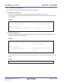
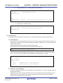
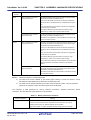
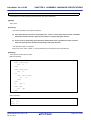
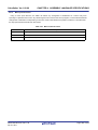
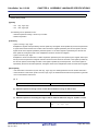
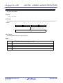
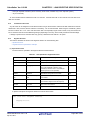
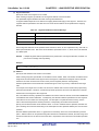
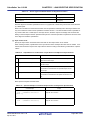
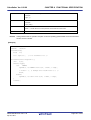
2.1.2
CHAPTER 2 FUNCTIONS
Changing allocated section
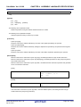
The default allocation sections are as follows:
- Variables with no initial value: .sbss section
- Variables with initial value: .sdata section
- const constants: .const section
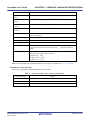
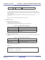
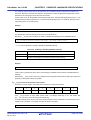
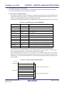
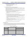
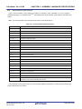
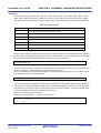
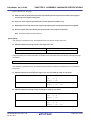
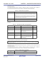
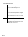
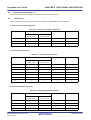
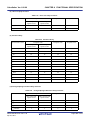
To change the allocated section specify the section type using #pragma section.
#pragma section section-type begin
variable-declaration/definition
#pragma section section-type end
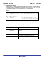
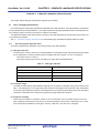
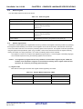
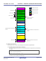
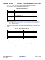
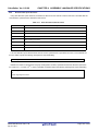
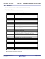
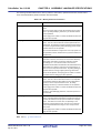
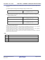
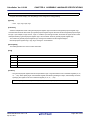
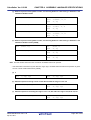
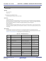
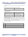
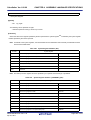
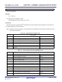
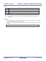
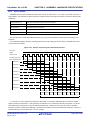
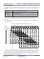
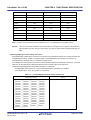
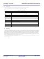
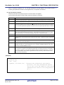
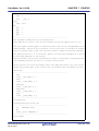
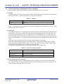
The relationship between section type and the section generated is as follows.
Section Type
data
Initial Value
Default Section
Section Name
Name
Change
Base Register
Access Instruction
Yes
.data
Possible
gp
ld/st 2 instruction
No
.bss
Possible
gp
ld/st 2 instruction
Yes
.sdata
Possible
gp
ld/st 1 instruction
No
.sbss
Possible
gp
ld/st 1 instruction
Yes
.sedata
Not Possible
ep
lld/st 1 instruction
No
.sebss
Not Possible
ep
ld/st 1 instruction
Yes
.sidata
Not Possible
ep
ld/st 1 instruction
No
.sibss
Not Possible
ep
ld/st 1 instruction
Yes
.tidata.byte
Not Possible
ep
sld/sst 1 instruction
No
.tibss.byte
Not Possible
ep
sld/sst 1 instruction
Yes
.tidata.word
Not Possible
ep
sld/sst 1 instruction
No
.tibss.word
Not Possible
ep
sld/sst 1 instruction
sconst
Yes
.sconst
Possible
r0
ld/st 1 instruction
const
Yes
.const
Possible
r0
ld/st 1 instruction
sdata
sedata
sidata
tidata.byte
tidata.word
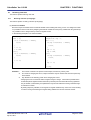
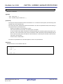
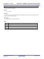
Example
#pragma section sdata "mysdata" begin
int a = 1;
/*allocated to mysdata.sdata attribute section*/
int b;
/*allocated to mysdata.sbss attribute section*/
#pragma section sdata "mysdata" end
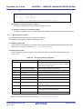
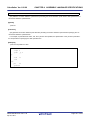
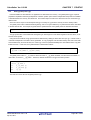
When referencing a variable using the #pragma section instruction from a function in another file (i.e. reference file), it
is necessary to also specify the #pragma section instruction in the reference file and to define the affected variable as
extern format.
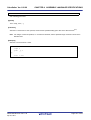
Example File that defines a table
R20UT0553EJ0100 Rev.1.00
Apr 01, 2011
Page 15 of 943
CubeSuite+ Ver.1.00.00
#pragma section sconst
CHAPTER 2 FUNCTIONS
begin
const unsigned char table_data[9] = {1, 2, 3, 4, 5, 6, 7, 8, 9};
#pragma section sconst
end
Example File that references a table
#pragma section sconst
begin
extern const unsigned char
#pragma section sconst
Remark
table_data[];
end
See "#pragma section directive" .
R20UT0553EJ0100 Rev.1.00
Apr 01, 2011
Page 16 of 943
CubeSuite+ Ver.1.00.00
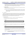
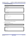
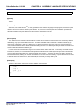
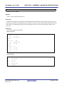
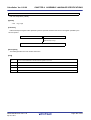
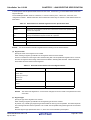
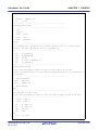
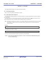
2.1.3
CHAPTER 2 FUNCTIONS
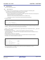
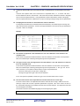
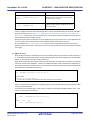
Defining variables for use during standard and interrupt processing
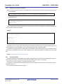
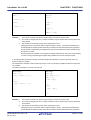
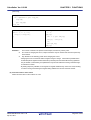
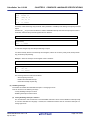
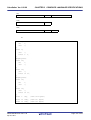
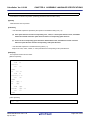
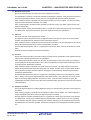
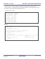
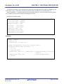
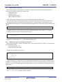
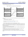
Specify as volatile variables that are to be used during both standard and interrupt processing.
When a variable is defined with the volatile qualifier, the variable is not optimized and optimization for assigning the
variable to a register is no longer performed. When a variable specified as volatile is manipulated, a code that always
reads the value of the variable from memory and writes the value to memory after the variable is manipulated is output.
The access width of the variable with volatile specified is not changed. A variable for which volatile is not specified is
assigned to a register as a result of optimization and the code that loads the variable from the memory may be deleted.
When the same value is assigned to variables for which volatile is not specified, the instruction may be deleted as a result
of optimization because it is interpreted as a redundant instruction.
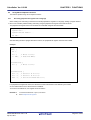
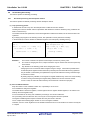
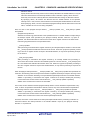
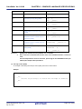
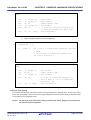
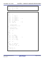
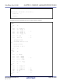
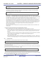
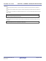
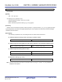
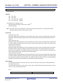
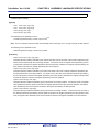
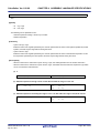
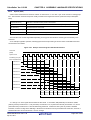
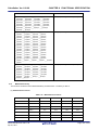
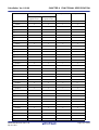
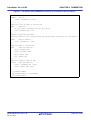
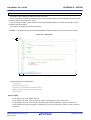
[Example of source and output code when volatile has been specified]
If volatile is specified for "variable a", "variable b", and "variable c", a code that always reads the values of these variables from memory and writes them to memory after the variables are manipulated is output. Even if an interrupt occurs
in the meantime and the values of the variables are changed by the interrupt, for example, the result in which the change
is reflected can be obtained. (In this case, interrupts may have to be disabled while the variables are manipulated,
depending on the timing of the interrupt.)
When volatile is specified, the code size increases compared with when volatile is not specified because the memory
has to be read and written.
volatile int a;
_func:
volatile int b;
.option volatile
volatile int c;
ld.w $_a, r10
void func(void) {
.option novolatile
if (a <= 0) {
cmp r0, r10
b++;
jgt .L2
} else {
.option volatile
c++;
ld.w $_b, r11
}
.option novolatile
b++;
add 1, r11
c++;
.option volatile
}
st.w r11, $_b
.option novolatile
jbr .L3
.L2:
.option volatile
ld.w $_c, r12
.option novolatile
add 1, r12
.option volatile
st.w r12, $_c
.option novolatile
.L3:
.option volatile
ld.w $_b, r13
.option novolatile
add 1, r13
.option volatile
R20UT0553EJ0100 Rev.1.00
Apr 01, 2011
Page 17 of 943
CubeSuite+ Ver.1.00.00
CHAPTER 2 FUNCTIONS
st.w r13, $_b
.option novolatile
.option volatile
ld.w $_c, r14
.option novolatile
add 1, r14
.option volatile
st.w r14, $_c
.option novolatile
jmp [lp]
R20UT0553EJ0100 Rev.1.00
Apr 01, 2011
Page 18 of 943
CubeSuite+ Ver.1.00.00
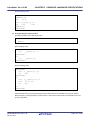
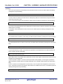
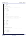
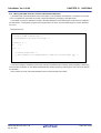
2.1.4
CHAPTER 2 FUNCTIONS
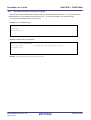
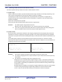
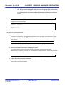
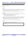
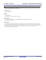
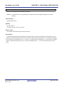
Defining user port
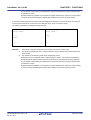
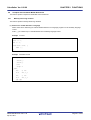
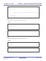
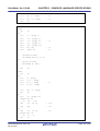
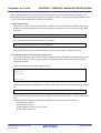
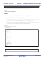
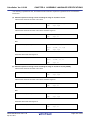
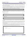
With regards to the user port, specify volatile as in the following example to avoid optimization.
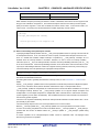
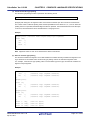
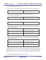
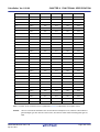
[Example of port description process]
/* 1.Port macro (format) definition*/
#define DEFPORTB(addr)
(*((volatile unsigned char *)addr))
/* 8-bit port*/
#define DEFPORTH(addr)
(*((volatile unsigned short *)addr))
/* 16-bit port*/
#define DEFPORTW(addr)
(*((volatile unsigned int *)addr))
/* 32-bit port*/
/* 2.Port definition (Example: PORT1 0x00100000 8bit)*/
#define PORT1
DEFPORTB(0x00100000)
/* 0x00100000
8-bit port*/
/* 3. Port use*/
{
PORT1 = 0xFF;
/* Write to PORT1*/
a = PORT1;
/* Read from PORT1*/
}
/* 4.C Compiler output code*/
:
mov
1048576, r10
#@BEGIN_VOLATILE
st.b
r20, [r10]
#@END_VOLATILE
mov
1048576, r11
#@BEGIN_VOLATILE
ld.b
[r11], r12
#@END_VOLATILE
:
Remarks 1.
By declaring a structure and assigning that structure variable to a specific section, and then assigning it
to the corresponding port address in the link directive, bit access is possible in the same "X.X" format
used in the CA850 internal region I/O register.
However, in the case of 1-bit or 8-bit access both the bit field and byte union are required, so the format
becomes "X.X.X".
2.
Assigning variables to sections should be performed using #pragma section or the section file.
R20UT0553EJ0100 Rev.1.00
Apr 01, 2011
Page 19 of 943
CubeSuite+ Ver.1.00.00
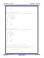
2.1.5
CHAPTER 2 FUNCTIONS
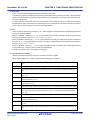
Defining const constant pointer
The pointer is interpreted differently depending on the "const" specified location.
To assign the const section to the sconst section, specify #pragma section sconst.
- const char *p;
This indicates that the object (*p) indicated by the pointer cannot be rewritten.
The pointer itself (p) can be rewritten.
Therefore the state becomes as follows and the pointer itself is allocated to RAM (.sdata/.data).
*p = 0;
/*Error*/
p = 0;
/*Correct*/
- char *const p;
This indicates that the pointer itself (p) cannot be rewritten.
The object (*p) indicated by the pointer can be rewritten.
Therefore the state becomes as follows and the pointer itself is allocated to ROM (.sconst/.const).
*p = 0;
/*Correct*/
p = 0;
/*Error*/
- const char *const p;
This indicates that neither the pointer itself(p) nor the object (*p) indicated by the pointer can be rewritten.
Therefore the state becomes as follows and the pointer itself is allocated to ROM (.sconst/.const).
*p = 0;
/*Error*/
p = 0;
/*Error*/
R20UT0553EJ0100 Rev.1.00
Apr 01, 2011
Page 20 of 943
CubeSuite+ Ver.1.00.00
2.2
CHAPTER 2 FUNCTIONS
Functions
This section explains functions.
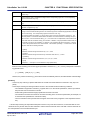
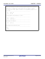
2.2.1
Changing area to be allocated to
When changing a function's section name, specify the function using the #pragma text directive as shown below.
#pragma text
["section name"]
#pragma text
["section name"]
function name
For a text attribute section that has had its section name changed, specify the initial section name from the time the
input section was created in a link directive.
Example The link directive coding method for when [#pragma text "sec1" func1] has been coded in the C source,
allocating function "func1" to the independently generated text-attribute section "sec1" (segment name:
FUNC1):
FUNC1:
!LOAD ?RX{
sec1.text = $PROGBITS ?AX sec1.text;
};
When allocating a specific function to an independently specified text-attribute section using the #pragma text directive,
the section name actually generated will be "(specified character string)+.text", and the section name must be entered in
the link directive.
In the above example it would be "sec1.text section".
Remark
See "#pragma text directive" .
R20UT0553EJ0100 Rev.1.00
Apr 01, 2011
Page 21 of 943
CubeSuite+ Ver.1.00.00
2.2.2
CHAPTER 2 FUNCTIONS
Calling an away function
The C compiler uses the jarl instruction to call functions.
However, depending on the program allocation the address may not be able to be resolved, resulting in an error when
linking because the jarl instruction is 22-bit displacement.
In such a case, it is possible to make the function call not depend on the displacement amount by using the C compiler's -Xfar_jump option.
This is called the far jump function.
When calling a function set as far jump, the jmp instruction rather than the jarl/jal instruction is output.
One function is described per line in the file where the -Xfar_jump option is specified. The names described should be
C language function names prefixed with "_" (an underscore).
Example
_func_led
_func_beep
_func_motor
:
:
_func_switch
If the following is described in place of "_function-name", all functions will be called using far jump.
{all_function}
Remark
See "far jump function" .
R20UT0553EJ0100 Rev.1.00
Apr 01, 2011
Page 22 of 943
CubeSuite+ Ver.1.00.00
2.2.3
CHAPTER 2 FUNCTIONS
Embedding assembler instructions
With the CA850 assembler instructions can be described in the following formats within C language source programs.
- asm declaration
__asm( character string constant);
or
__asm( character string constant);
- #pragma directive
#pragma asm
Assembler instruction
#pragma endasm
To use registers with an inserted assembler, save or restore the contents of the registers in the program because they
are not saved or restored by the CA850.
Example
__asm("nop ");
__asm(".str \"string\\0\"");;
#pragma asm
mov r0, r10
st.w r10, $_i
#pragma endasm
Assembler instructions written within asm declarations and between #pragma asm and #pragma endasm directives are
never expanded even if the assembler source contains material defined by C language #define.
Furthermore assembler instructions written within asm declarations and between #pragma asm and #pragma endasm
directives are not expanded even if the -P option is added in the C compiler because they are passed as is to the assembler.
Remark
2.2.4
See "Describing assembler instruction" .
Executing in RAM
A program allocated to external ROM can be copied to internal RAM and executed in internal RAM while linking and
after copying if the relative value of each section and each symbol (TP, EP, GP) is not destroyed.
Use caution, as some programs can be copied while others cannot.
If a program is copied to internal RAM following reset and is not changed, this can be done more easily by using the
ROMization function.
The text section can be packed with romp850.
R20UT0553EJ0100 Rev.1.00
Apr 01, 2011
Page 23 of 943
CubeSuite+ Ver.1.00.00
2.3
CHAPTER 2 FUNCTIONS
Using Microcomputer Functions
This section explains using microcomputer functions.
2.3.1
Accessing peripheral I/O register with C language
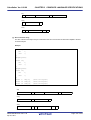
When reading from and writing to the device's internal peripheral I/O register in C language, adding a pragma directive
to the C source makes possible reading and writing using the peripheral I/O register name and bit names.
The peripheral I/O register name can be treated as a standard unsigned external variable.
#pragma ioreg
register name = ...
register name.bit number = ...
bit name = ...
After describing the above pragma directive as above, the peripheral I/O register name becomes usable.
Example
#pragma ioreg
main() {
int i;
P0 = 1;
/* Writes 1 to P0*/
i = RXB0;
/* Reads from RXB0*/
}
void func(void) {
P1 = 0;
/* Writes 0 to P1*/
}
void func2(void) {
P0.1 = 1;
/* Sets bit 1 of PO to 1*/
P2.3 = 0;
/* Sets bit 3 of P2 to 0*/
PS00 = 1;
/* Sets the bit named PSOO to 1*/
}
For peripheral I/O register bit names, the relevant bit names are limited to ones defined by the CA850.
An error will therefore occur if the bit name is undefined.
To access an undefined bit, use "register name.bit number".
Remarks 1.
2.
To access the 4th bit of C port 3, use "P3.4".
See "Peripheral I/O register" .
R20UT0553EJ0100 Rev.1.00
Apr 01, 2011
Page 24 of 943
CubeSuite+ Ver.1.00.00
2.3.2
CHAPTER 2 FUNCTIONS
Describing interrupt processing with C language
With the CA850, the interrupt handler is specified using the "#pragma interrupt directive" and "__interrupt qualifier" (for
standard interrupt), or the "#pragma interrupt directive" and "__multi_interrupt qualifier" (for multiple interrupt).
An example of the interrupt handler is shown below.
Example Non-maskable interrupt
#pragma interrupt NMI func1
/*non-maskable interrupt*/
__interrupt
void func1(void) {
:
}
Example Multiple interrupt specification
#pragma interrupt INTP0 func2
__multi_interrupt
/* multiple-interrupt function specified*/
void func2(void) {
:
}
Remark
See "Interrupt/Exception processing handler" .
R20UT0553EJ0100 Rev.1.00
Apr 01, 2011
Page 25 of 943
CubeSuite+ Ver.1.00.00
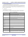
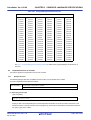
2.3.3
CHAPTER 2 FUNCTIONS
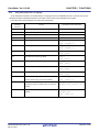
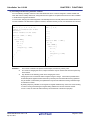
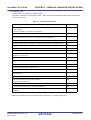
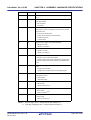
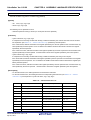
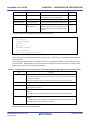
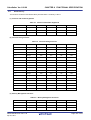
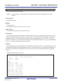
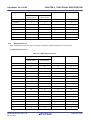
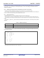
Using CPU instructions in C language
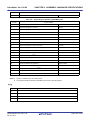
Some assembler instructions can be described in C language source as embedded functions. However, they are not
described exactly as assembler instructions, but rather in the function format prepared by the CA850.
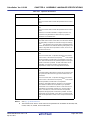
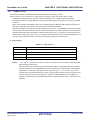
Instructions that can be described as functions are shown below.
Assembler
Function
Embedded Function Description
Instruction
di
Interrupt control (ei)
__DI()
ei
Interrupt control (di)
__EI()
nop
nop
__nop()
halt
halt
__halt()
satadd
Saturated addition (satadd)
long a, b;
long __satadd(a, b);
satsub
Saturated subtraction (satsub)
long a, b;
long __satsub(a, b);
bsh
Halfword data byte swap (bsh) [V850E]
long a;
long __bsh(a);
bsw
Word data byte swap (bsw) [V850E]
long a;
long __bsw(a);
hsw
Word data halfword swap (hsw) [V850E]
long a;
long __hsw(a);
sxb
Byte data sign extension (sxb) [V850E]
char a;
long __sxb(a);
sxh
Halfword data sign extension (sxh) [V850E]
short a;
long __sxh(a);
mul
mulu
Instruction that assigns higher 32 bits of multiplication
long a; long b;
result to variable using mul instruction [V850E]
long __mul32(a, b);
Instruction that assigns higher 32 bits of unsigned
unsigned long a, b;
multiplication result to variable using mulu instruction
unsigned long __mul32u(a, b);
[V850E]
sasf
Flag condition setting with logical left shift (sasf)
long a;
[V850E]
unsigned int b;
long __sasf(a, b);
R20UT0553EJ0100 Rev.1.00
Apr 01, 2011
Page 26 of 943
CubeSuite+ Ver.1.00.00
CHAPTER 2 FUNCTIONS
Example
long a, b, c;
void func(void) {
:
c = __satsub(a, b); /* The result of the saturated operation of a and b is stored in c
(c = a - b) */
:
__nop();
:
}
Remark
See "Embedded functions" .
R20UT0553EJ0100 Rev.1.00
Apr 01, 2011
Page 27 of 943
CubeSuite+ Ver.1.00.00
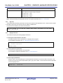
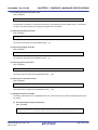
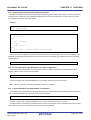
2.3.4
CHAPTER 2 FUNCTIONS
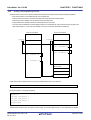
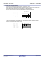
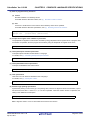
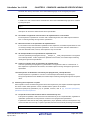
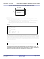
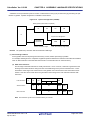
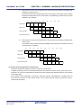
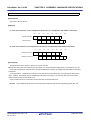
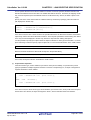
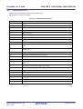
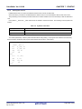
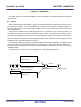
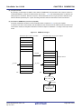
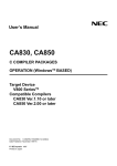
Creating a self-programming boot area
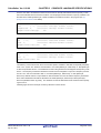
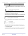
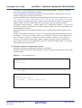
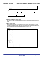
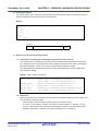
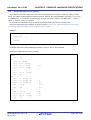
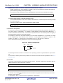
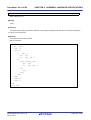
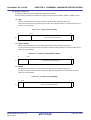
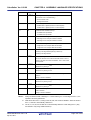
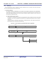
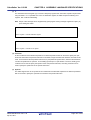
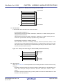
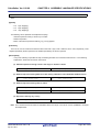
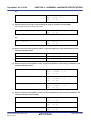
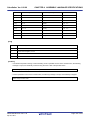
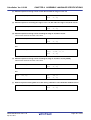
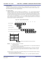
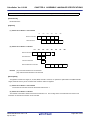
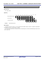
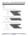
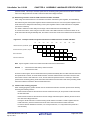
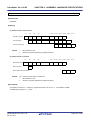
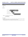
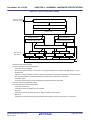
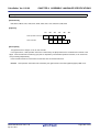
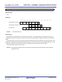
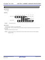
Variables and functions can be referenced between the flash area and boot area with the following operations.
- Boot area functions can be called directly from the flash area.
- Calling a function from the boot area to the flash area is performed via a branch table.
- External boot area variables can be referenced from the flash area.
- External flash area variables cannot be referenced from the boot area.
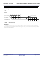
- Common external variables as well as global functions can be defined for use by both boot area programs and
flash area programs. In this case the variable or function on the same area side is referenced.
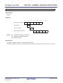
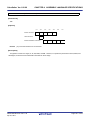
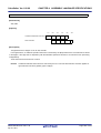
Boot Area Side ROM
_bootfunc:
Flash Area Side ROM
_flashfunc:
jarl
_bootfunc, lp
jarl
_flashfunc, lp
jarl
_bootfunc, lp
jarl
_flashfunc, lp
Branch Table
ID:1
jr
...
ID:0
jr
_flashfunc
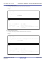
Flash area functions called from the boot area are defined with the ext_func directive.
.ext_func function name, ID number
[Example (Within a C language program)]
#pragma asm
.ext_func _func_flash0, 0
.ext_func _func_flash1, 1
.ext_func _func_flash2, 2
#pragma endasm
Additional specifications such as options must be made. See "Flash relink function" in the "V850 Build" for details.
R20UT0553EJ0100 Rev.1.00
Apr 01, 2011
Page 28 of 943
CubeSuite+ Ver.1.00.00
2.4
CHAPTER 2 FUNCTIONS
Variables (Assembler)
This section explains variables (Assembler).
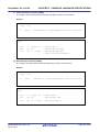
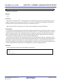
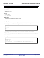
2.4.1
Defining variables with no initial values
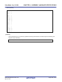
Use the .lcomm directive in a section with no initial value to allocate area for a variable with no initial value.
.lcomm label name, size, alignment condition
In order that it may be referenced from other files as well, it is necessary to define the label with the .globl directive.
.globl label name[, size]
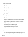
[Example]
.globl val0
-- Sets val0 as able to be referenced from other files
.globl val1
-- Sets val1 as able to be referenced from other files
.globl val2
-- Sets val2 as able to be referenced from other files
.sbss
.lcomm val0,4,4
-- Allocates 4 bytes of area for val0 and sets its alignment
condition to 4
.lcomm val1,2,2
-- Allocates 2 bytes of area for val1 and sets its alignment
condition to 2
.lcomm val2,1,1
-- Allocates 1 byte of area for val2 and sets its alignment
condition to 1
Remark
See ".lcomm", ".globl" .
R20UT0553EJ0100 Rev.1.00
Apr 01, 2011
Page 29 of 943
CubeSuite+ Ver.1.00.00
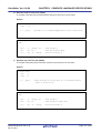
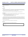
2.4.2
CHAPTER 2 FUNCTIONS
Defining const constants with initial values
To define a const with an initial value, use the following directives within the .const or .sconst section.
- 1-byte values
.byte value[, value, ...]
- 2-byte values
.hword value[, value, ...]
- 4-byte values
.word value[, value, ...]
Example Allocates 1 halfword and stores 100
.const
.align 4
.globl _p, 2
_p:
.hword 100
Remark
See ".byte", ".hword", ".word" .
R20UT0553EJ0100 Rev.1.00
Apr 01, 2011
Page 30 of 943
CubeSuite+ Ver.1.00.00
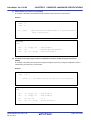
2.4.3
CHAPTER 2 FUNCTIONS
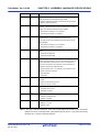
Referencing section addresses
Symbols such as .data and .sdata (reserved symbols) which point to the beginnings and ends of sections are available.
Therefore, utilize the appropriate symbol name when using the address value of a specified section from the assembler
source.
Start symbol:
__s[section name]
End symbol:
__e[section name]
For example, the start symbol for the .sbss section is __ssbss, and its end symbol is __esbss.
These symbols can be used to retrieve the section start address and end address, but these symbol names cannot be
used to make direct references with C language labels.
To retrieve these symbol values, create global variables to store these values then store the symbol values in the variables in assembler source such as that of the start up module.
By referencing these variables in the C source this can be realized.
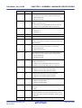
The same applies to symbols such as __gp_DATA.
For example, the method for retrieving the start and end addresses of a .data section is as follows.
[In assembler source]
.comm
_data_top, 4, 4
.comm
_data_end, 4, 4
.extern __sdata, 4
.extern __edata, 4
mov
#__sdata, r12
st.w
r12, $_data_top
mov
#__edata, r13
st.w
r13, $_data_end
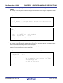
[In C source]
extern
int data_top;
/* extern defines data_top*/
extern
int data_end;
/* extern defines data_end*/
void func1(void){
int top, end;
top = data_top;
end = data_end;
:
}
Try using this method in cases where a C language label is used to initialize only a specified section.
R20UT0553EJ0100 Rev.1.00
Apr 01, 2011
Page 31 of 943
CubeSuite+ Ver.1.00.00
2.5
CHAPTER 2 FUNCTIONS
Startup Routine
This section explains startup routine.
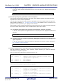
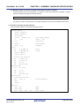
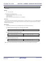
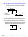
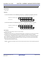
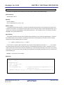
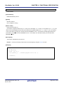
2.5.1
Secure stack area
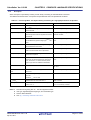
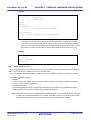
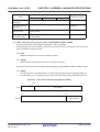
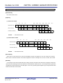
When setting a value to the stack pointer (sp), it is necessary to pay attention to the following points.
- The stack frame is generated downwards starting from the sp set value.
- Be sure to set the sp to point at the of 4-byte boundary position.
When the compiler references memory relative to a stack, it generates code based on the assumption the
stack pointer points at the 4-byte boundary position.
Allocate it to a data section (bss attribute section) as far as possible from gp.
If it is near the gp, there is a chance that the program data area will be destroyed.
[sp setting example]
.set
STACKSIZE, 0x3f0
.bss
.lcomm
__stack, STACKSIZE, 4
mov
#__stack + STACKSIZE, sp
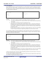
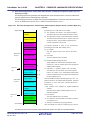
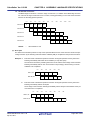
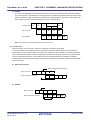
In the above example, the size of the stack frame used by the application is set to 0x3f0 bytes and area is secured.
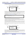
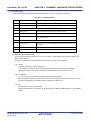
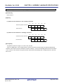
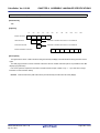
The label "__stack" points to the lowest position (start) of the stack frame.
Because __stack is not external variable defined (via .globl declaration) in the default startup module, __stack cannot
be referenced from other files.
If a .globl declaration is executed to __stack it becomes possible to be referenced by other files.
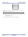
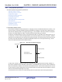
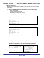
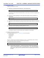
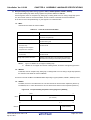
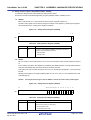
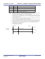
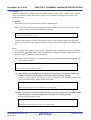
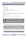
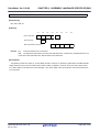
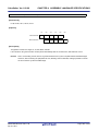
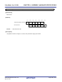
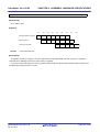
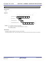
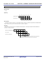
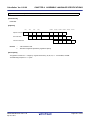
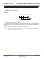
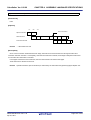
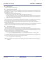
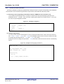
The stack area defines the __stack symbol to the lowest position address and sets the sum address and size of
__stack to the stack pointer.
Therefore there is no symbol for the end address.
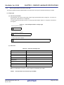
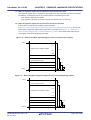
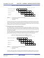
By doing the following, it becomes possible to define the next address after the stack area end address.
Use caution, as it is not the last address in the stack area.
.set
STACKSIZE, 0x200
.bss
.globl
__stack
--added
.globl
__stack_end
--added
.lcomm
__stack, STACKSIZE, 4
.lcomm
__stack_end, 0, 0
--added
With the above definition, it is possible to refer to _stack and _stack_end symbols in the C source.
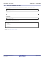
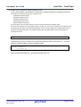
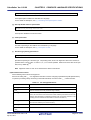
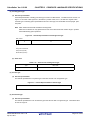
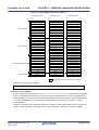
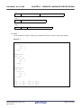
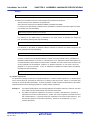
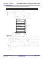
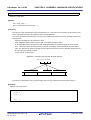
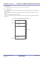
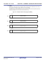
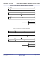
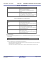
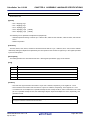
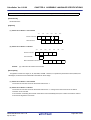
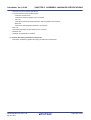
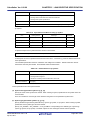
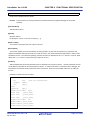
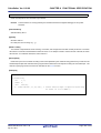
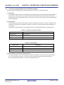
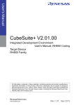
The mapping image becomes as follows.
R20UT0553EJ0100 Rev.1.00
Apr 01, 2011
Page 32 of 943
CubeSuite+ Ver.1.00.00
CHAPTER 2 FUNCTIONS
__stack_end
Stack Area
__stack
0x0
The size of the __stack symbol is specified in the startup module and should therefore be defined in C source in an
array as follows.
Use caution because it is not the last address in the stack area.
extern unsigned long
Remark
_stack[];
When using a label defined in the assembler in C language, one underscore is removed from the start of its
name.
Assembly language definition:__stack
Reference with C language : stack
The stack usage tracer (slk850) can be used to measure C source program stack area.
R20UT0553EJ0100 Rev.1.00
Apr 01, 2011
Page 33 of 943
CubeSuite+ Ver.1.00.00
2.5.2
CHAPTER 2 FUNCTIONS
Securing stack area and specifying allocation
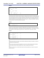
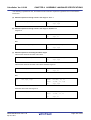
This section explains securing stack area and specifying allocation.
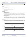
(1) Secure stack area
In the startup routine, secure a stack in a section of a variable with no initial value with a specified section name.
[Example of setting sp]
.set
STACKSIZE, 0x200
.section
".stack", bss
.lcomm
__stack, STACKSIZE, 4
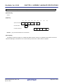
In the above example the section of the stack frame to be used by the application is set to .stack, the size is specified as 0x200 bytes and the area is secured.
The label "__stack" points to the lowest position (start) of the stack frame.
(2) Specify stack area allocation
In the link directive file specify the allocation of the section created in (1).
[Example of allocation specification]
STACK
: !LOAD ?RW V0x3ffee00 {
.stack
= $NOBITS
?AW
.stack;
};
In the above example the stack segment is called STACK, and is allocated to the address 0x3ffee00.
R20UT0553EJ0100 Rev.1.00
Apr 01, 2011
Page 34 of 943
CubeSuite+ Ver.1.00.00
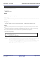
2.5.3
CHAPTER 2 FUNCTIONS
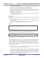
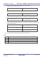
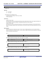
Initializing RAM
This section explains initializing RAM.
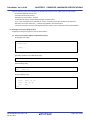
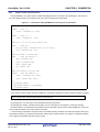
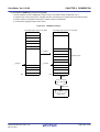
(1) Variables with no initial value
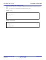
Processing to clear the .sbss and .bss sections with 0 is embedded in the default startup routine.
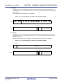
When clearing sections other than those above is desired, add such processing to the startup routine. When clearing, use the symbols that indicate the section start and end.
Example Clear the .tibss.byte section
.extern __stibss.byte, 4
-- .tibss.byte area start symbol
.extern __etibss.byte, 4
-- .tibss.byte area end symbol
mov #__stibss.byte, r13
mov #__etibss.byte, r12
cmp r12, r13
jnl .L20
.L21:
st.w r0, [r13]
add 4, r13
cmp r12, r13
jl .L21
.L20:
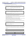
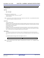
(2) RAM initialization
When a load module has been downloaded to the in-circuit emulator without performing ROMization, data with initialized values placed in regions such as the data and sdata areas are set to their values at the time of download.
When using the load module output by the linker to debug, it is necessary to remove the RAM area initialization
routine.
In the case of a ROMization load module, it is necessary to use the _rcopy copy function to perform operations
such as copying data with initial values.
This processing is possible not in the startup routine but also before accessing a main function variable with an initial value, so perform it upon full completion of peripheral settings.
R20UT0553EJ0100 Rev.1.00
Apr 01, 2011
Page 35 of 943
CubeSuite+ Ver.1.00.00
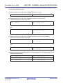
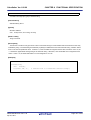
2.5.4
CHAPTER 2 FUNCTIONS
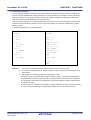
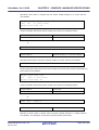
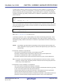
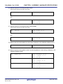
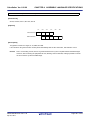
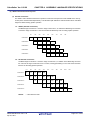
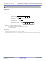
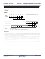
Preparing function and variable access
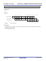
The text pointer is used when accessing a function, and either the global pointer or the element pointer is used when
accessing a variable
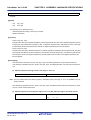
(1) Preparations for accessing a function
The text pointer (tp) is a pointer prepared to implement referencing (PIC: Position Independent Code) independent
of the position at which the text area of an application, i.e., program code is allocated when the program code is
referenced. For example, if it is necessary to reference a specific location in the code during program execution,
the CA850 outputs the code to be accessed in tp-relative mode.
Since the code is output on the assumption that tp is correctly set, tp must be correctly set in the startup routine.
The text pointer value is determined during linking, and is in a symbol defined by a symbol directive that is
described in the link directive file. For example, suppose that the symbol directive of the text pointer is described
as follows.
__tp_TEXT @ %TP_SYMBOL {TEXT};
The text pointer value is the beginning of the TEXT segment, and is in "__tp_TEXT".
Describe as follows to set tp in the startup routine.
.extern __tp_TEXT, 4
mov
#__tp_TEXT, tp
R20UT0553EJ0100 Rev.1.00
Apr 01, 2011
Page 36 of 943
CubeSuite+ Ver.1.00.00
CHAPTER 2 FUNCTIONS
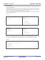
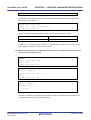
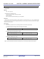
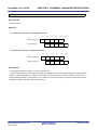
(2) Variable access preparations (Setting global pointer)
External variables or data defined in an application are allocated to the memory. The global pointer (gp) is a
pointer prepared to implement referencing independent of location position (PID: Position Independent Data) when
the variables or data allocated to the memory are referenced. The CA850 outputs a code for the section that is to
be accessed in gp-relative mode.
Since the code is output on the assumption that gp is correctly set, gp must be correctly set in the startup routine.
The global pointer value is determined during linking, and is in a symbol defined by a symbol directive that is
described in the link directive file. For example, suppose that the symbol directive of the global pointer is described
as follows.
__gp_DATA @ %GP_SYMBOL {DATA};
The gp symbol value can be defined the beginning of "data segment" of the DATA segment as shown above, or
offset from a text symbol. A gp symbol can be specified not only by specifying the start address of a data segment
(such as the DATA segment), but also by using an offset value from the text symbol as its address.
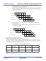
Using the second method, the gp symbol value is determined by adding an offset value from tp to tp. In other
words, a code that is independent of location can be generated. To copy a program code and data used by that
code to the RAM area simultaneously and execute them, the value of gp can be acquired immediately if the start
address of the copy destination is known. In this case, the symbol directive is described as follows.
__tp_TEXT @ %TP_SYMBOL;
__gp_DATA @ %GP_SYMBOL &__tp_TEXT {DATA};
The global pointer value is "__tp_TEXT to which the value of __gp_DATA is added", and the value to be added,
i.e., offset value, is stored in "__gp_DATA". Therefore, describe as follows to set gp in the startup routine.
.extern __tp_TEXT, 4
.extern __gp_DATA, 4
mov
#__tp_TEXT, tp
mov
#__gp_DATA, gp
add
tp, gp
This sets the correct value of the global pointer to gp.
R20UT0553EJ0100 Rev.1.00
Apr 01, 2011
Page 37 of 943
CubeSuite+ Ver.1.00.00
CHAPTER 2 FUNCTIONS
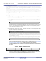
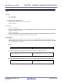
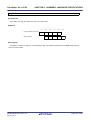
(3) Variable access preparations (Setting element pointer)
Of the external variables or data defined in an application, those that are allocated to the following sections are
accessed from the element pointer (ep) in relative mode.
- sedata/sebss attribute section
- sidata/sibss attribute section
- tidata/tibss attribute section
- tidata.byte/tibss.byte section
- tidata.word/tibss.word section
If these sections exist, the CA850 outputs a code to access these areas in ep-relative mode.
Since the code is output on the assumption that ep is correctly set, ep must be correctly set in the startup routine.
The element pointer value is determined during linking, and is in a symbol defined by a symbol directive that is
described in the link directive file. For example, suppose that the symbol directive of the element pointer is
described as follows.
__ep_DATA @ %EP_SYMBOL;
The element pointer value is the beginning of the SIDATA segment by default, and its value is in "__ep_DATA".
Therefore, describe as follows to set ep in the startup routine.
.extern __ep_DATA, 4
mov
#__ep_DATA, ep
Reference the absolute address of __ep_DATA and set that value to ep.
R20UT0553EJ0100 Rev.1.00
Apr 01, 2011
Page 38 of 943
CubeSuite+ Ver.1.00.00
2.5.5
CHAPTER 2 FUNCTIONS
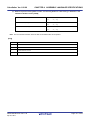
Preparing to use code size reduction function
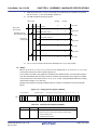
This setting is necessary to reduce code size when the V850Ex core is used or when the prologue/epilogue runtime
library is used (i.e. When higher optimization (execution speed priority) is not specified or when "-Xpro_epi_runtime=on"
is specified).
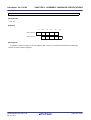
Since the CALLT instruction is used when the prologue/epilogue runtime library of functions is called by the V850Ex
core, the value of CTBP necessary for the CALLT instruction must be set at the beginning of the function table of the prologue/epilogue runtime library of functions.
The prologue/epilogue runtime library is used in the following case
- Compiler option "-Xpro_epi_runtime=on" is set
If a compiler option except "-Ot" is specified for optimization, "-Xpro_epi_runtime=on" is automatically specified.
The start symbol for the function prologue/epilogue runtime library function table is as follows.
- ___PROLOG_TABLE
Describe the following code using this symbol.
mov #___PROLOG_TABLE, r12
ldsr r12, 20
CTBP is system register 20. Set a value to it using the ldsr instruction.
R20UT0553EJ0100 Rev.1.00
Apr 01, 2011
Page 39 of 943
CubeSuite+ Ver.1.00.00
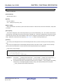
2.5.6
CHAPTER 2 FUNCTIONS
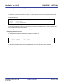
Ending startup routine
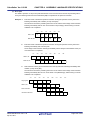
The final process in the startup routine differs depending on whether or not a real-time OS is used.
(1) When not using a real-time OS
When the processing necessary for the startup routine has been completed, execute an instruction that branches
to the main function.
Describe the following code to branch to the main function.
jarl _main, lp
When the main function has been executed, execution returns to the 4 bytes subsequent to this branch instruction.
The following instruction can also be used if it is known that execution does not return.
jr _main
mov #_main, lp
jmp [lp]
The entire 32-bit space can be accessed using the jmp instruction. When the "jarl_main, lp" instruction is used,
execution returns after the main function is executed. It is recommended to take appropriate action to prevent
deadlock from occurring when execution returns.
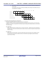
(2) When using a real-time OS (RI850V4)
In an application using a real-time OS, execution branches to the initialization routine when the processing that
must be performed by the startup routine has been completed.
.extern __kernel_sit
.extern __kernel_start
mov
#__kernel_sit, r6
mov
#__kernel_start, r11
jarl
__jump_kernel_start, lp
__boot_error:
jbr
__boot_error
__jump_kernel_start:
jmp
[r11]
R20UT0553EJ0100 Rev.1.00
Apr 01, 2011
Page 40 of 943
CubeSuite+ Ver.1.00.00
2.6
CHAPTER 2 FUNCTIONS
Link Directives
This section explains link directives.
Link directive files can be generated automatically in CubeSuite+.
Remark
For information about how to automatically generate link directive files, see the "CubeSuite+ V850 Build"
user's Manual.
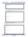
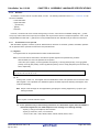
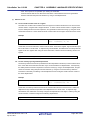
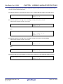
2.6.1
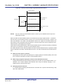
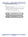
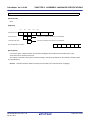
Adding function section allocation
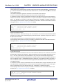
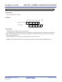
To perform function section allocation, divert the .text section setting portion and change the segment name and section name.
TEXT
: !LOAD ?RX {
.pro_epi_runtime = $PROGBITS
?AX
.pro_epi_runtime;
.text
?AX
.text;
= $PROGBITS
Divert
};
Example Setting allocation for USRTEXT segment and usr.text section
USRTEXT : !LOAD ?RX {
usr.text
= $PROGBITS
?AX
usr.text;
};
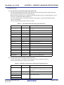
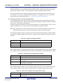
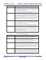
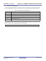
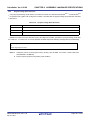
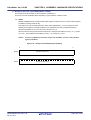
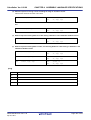
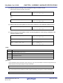
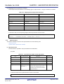
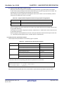
2.6.2
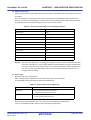
Adding section allocation for variables
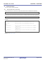
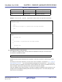
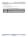
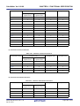
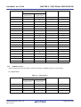
To add allocation settings for a variable section, divert the specification part for a section with the same attributes and
change the segment name and section name.
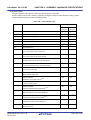
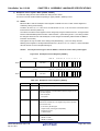
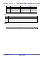
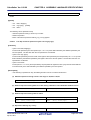
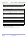
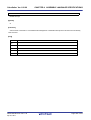
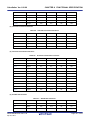
The section attributes specify the section type when the section is set to a variable in #pragma section.
Section Type
Section to Be Diverted
data
.data/.bss
sdata
.sdata/.sbss
sconst
.sconst
const
.const
Example Setting allocation for USRCONST segment and usr.const section
USRCONST
: !LOAD ?R {
usr.const
= $PROGBITS
?A usr.const;
};
R20UT0553EJ0100 Rev.1.00
Apr 01, 2011
Page 41 of 943
CubeSuite+ Ver.1.00.00
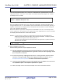
2.6.3
CHAPTER 2 FUNCTIONS
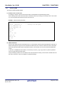
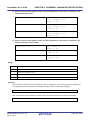
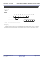
Distributing section allocation
The following three methods for distributing section allocation are available.
(1) Distribute by section name
In the C source or assembler source, specify separate names for the sections to be allocated.
By specifying individual input section names within the link directive, the section of each name will be allocated to
its specified part.
Example
TEXT : !LOAD ?RX{
.text = $PROGBITS ?AX .text ;
<- the .text section is allocated
};
FUNC1 : !LOAD ?RX{
funcsec1.text = $PROGBITS ?AX funcsec1.text ;
<- he funcsec.text section is allocated
};
(2) Distribute by object files
By specifying individual object names within the link directive, the section with the relevant attributes within each
object will be allocated to the specified part.
Example
TEXT1 : !LOAD ?RX {
.text1 = $PROGBITS ?AX { filel.o file2.o }; <- The TEXT ATTRIBUTE sections in file1.o and
file2.o are allocated.
};
TEXT2 : !LOAD ?RX{
.text2 = $PROGBITS ?AX { file3.o };
<- The TEXT ATTRIBUTE section in file3.o is
allocated.
};
When specifying the name an object file in a library (.a file), specify the .a file name including its path within parentheses.
Example
.text2 = $PROGBITS ?AX .text {rcopy.o(c:\micomtools\lib850\r32\libr.a)};
R20UT0553EJ0100 Rev.1.00
Apr 01, 2011
Page 42 of 943
CubeSuite+ Ver.1.00.00
CHAPTER 2 FUNCTIONS
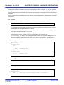
(3) Distribute by section attributes
Specify allocation only by attributes without specifying the input section and input object. Because this setting has
a lower priority level than the part where settings such as section name and object name are made, it can be used
to specify allocation for all parts where section and object names are not already specified.
Example
TEXT1 : !LOAD ?RX V0x100000{
.text1 = $PROGBITS ?AX{file1.o file2.o}; <- The TEXT ATTRIBUTE sections in file1.o and
file2.o are allocated.
};
TEXT2 : !LOAD ?RX V0x120000{
.text2 = $PROGBITS ?AX ;
<- The TEXT ATTRIBUTE sections in objects
other than file1.o and file2.o are allocated.
};
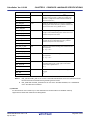
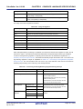
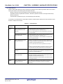
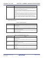
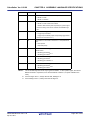
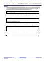
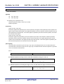
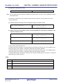
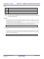
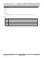
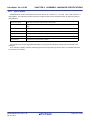
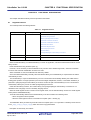
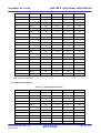
(4) Allocation specification priority level
There are priority levels depending on the presence or lack of input section and input object specifications. When
allocating sections, the linker allocates starting with the highest priority specification.
The relationship between priority level and specifications is shown below. (A lower the priority level number represents a higher priority.)
Priority
Specified Names
Output
Level
1
2
Input section name
The specified input section is extracted from the specified object and is
+ object file name
then output.
Input section name only
The specified input section is extracted from all objects and is then
output.
3
Object file name only
Sections having the same attribute as the output section to be created
are extracted from the specified object and are then output.
4
No names specified
Sections having the same attribute as the output section to be created
are extracted from all objects and are then ouput.
R20UT0553EJ0100 Rev.1.00
Apr 01, 2011
Page 43 of 943
CubeSuite+ Ver.1.00.00
2.7
CHAPTER 2 FUNCTIONS
Reducing Code size
This section explains reducing code size.
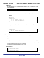
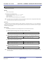
2.7.1
Reducing code size (C language)
This section explains reducing code size (C language).
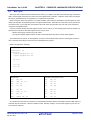
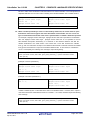
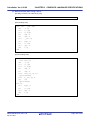
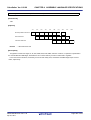
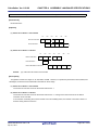
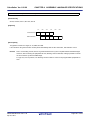
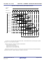
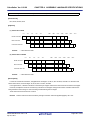
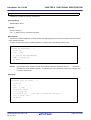
(1) Access to variables
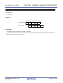
Because 4 bytes are needed each for external variable access loading and storing, even in non-assignment cases
it is possible to reduce code size by assigning the external variable into a temporary variable and using that temporary variable so as to change memory access to register access.
In the following example s is an external variable
Before change:
After change:
if(x != 0){
unsigned int
if((s & 0x00F00F00) != MASK1){
tmp = s;
if(x != 0){
return;
if((tmp & 0x00F00F00) != MASK1){
}
return;
s >>= 12;
}
s &= 0xFF;
tmp >>= 12;
}else{
tmp &= 0xFF;
if((s & 0x00FF0000) != MASK2){
}else{
return;
if((tmp & 0x00FF0000) != MASK2){
}
return;
s >>= 24;
}
}
tmp >>= 24;
}
s = tmp;
Remarks 1.
2.
The amount of reduction is specific to this example, and will vary case by case.
As a result of changing the source, output instructions may be reduced and execution speed may
be increased.
3.
Pay attention to the following points when changing the source.
- Changing the source causes the state of register usage to change. It is therefore possible that in
unintended places register transfers that had up until that point remained without being optimized
may be erased or, alternatively, that optimization may become ineffective causing redundant register transfers to remain.
- By adding temporary variables, a new register for register variables may come to be used, resulting
in code for saving and restoring that register being added to the function entrance and exit.
R20UT0553EJ0100 Rev.1.00
Apr 01, 2011
Page 44 of 943
CubeSuite+ Ver.1.00.00
CHAPTER 2 FUNCTIONS
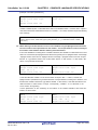
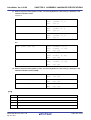
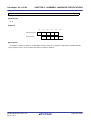
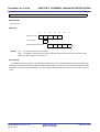
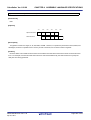
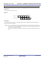
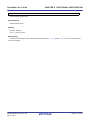
(2) Number of loops in loop processing
As in the following example, expanding a function may make its size smaller if the number of times to execute is
few and body of each loop is small.
In this case, the execution speed also increases.
Before change:
After change:
for(i = 0; i < 4; i++){
long
array[i] = 0;
}
*p;
:
p = array;
*p = 0;
*(p + 1) = 0;
*(p + 2) = 0;
*(p + 3) = 0;
Remarks 1.
2.
The amount of reduction is specific to this example, and will vary case by case.
As a result of changing the source, output instructions may be reduced and execution speed may
be increased.
3.
Pay attention to the following points when changing the source.
- Changing the source causes the state of register usage to change. It is therefore possible that in
unintended places register transfers that had up until that point remained without being optimized
may be erased or, alternatively, that optimization may become ineffective causing redundant register transfers to remain.
- By adding temporary variables, a new register for register variables may come to be used, resulting
in code for saving and restoring that register being added to the function entrance and exit.
R20UT0553EJ0100 Rev.1.00
Apr 01, 2011
Page 45 of 943
CubeSuite+ Ver.1.00.00
CHAPTER 2 FUNCTIONS
(3) auto variable initialization
When an auto variable is used within a function without being initialized, because that variable is not allocated to a
register and remains in memory, the code size may increase.
In the following example if neither switch case applies then variable a is referenced in the return statement without
being initialized.
Even if in actuality it will certainly apply to one of the cases it may not to be initialized because when the C compiler
allocates to register it is not understood when the program is analyzed.
In a case such as this, it cannot be allocated with CA850 register allocation.
By adding initialization it becomes able to be allocated to a register and the code size is reduced.
Before change:
After change:
int func(int x) {
int func(int x) {
int a;
int a = 0;
switch(x){
case
switch(x){
0:
case
0:
a = VAL0;
a = VAL0;
break;
break;
case
1:
case
a = VAL1;
1:
a = VAL1;
}
}
return(a);
return(a);
}
}
Remarks 1.
2.
The amount of reduction is specific to this example, and will vary case by case.
As a result of changing the source, output instructions may be reduced and execution speed may
be increased.
3.
Pay attention to the following points when changing the source.
- Changing the source causes the state of register usage to change. It is therefore possible that in
unintended places register transfers that had up until that point remained without being optimized
may be erased or, alternatively, that optimization may become ineffective causing redundant register transfers to remain.
- By adding temporary variables, a new register for register variables may come to be used, resulting
in code for saving and restoring that register being added to the function entrance and exit.
R20UT0553EJ0100 Rev.1.00
Apr 01, 2011
Page 46 of 943
CubeSuite+ Ver.1.00.00
CHAPTER 2 FUNCTIONS
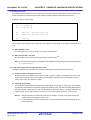
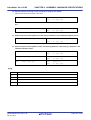
(4) switch statements
With respect to switch statements, if there are four or more case labels and the difference between each variable's
low limit and high limit is up to 3 times the number of cases, the CA850 generates code in table branch format.
In such an instance, if the number of cases is approximately 16 or less (this number varies depending on factors
such as the switch expression format and the label value distribution), changing them to equivalent if-else statements and putting comparison and branch instructions in line will cause the code size to decrease.
In cases such as when the switch expression is an external variable reference or is a complex expression, it is necessary to once substitute the value to a temporary variable and make the if expression refer to the temporary variable.
In the following example x is an auto variable.
Before change:
After change:
switch(x){
if(x == VAL0)
case
VAL0:
return(RETVAL0);
case
VAL1:
return(RETVAL1);
case
VAL2:
return(RETVAL2);
case
VAL3:
return(RETVAL3);
case
VAL4:
return(RETVAL4);
case
VAL5:
return(RETVAL0);
else if(x == VAL1)
return(RETVAL1);
else if(x == VAL2)
return(RETVAL2);
else if(x == VAL3)
return(RETVAL3);
else if(x == VAL4)
return(RETVAL4);
else if(x == VAL5)
return(RETVAL5);
return(RETVAL5);
}
Remarks 1.
2.
The amount of reduction is specific to this example, and will vary case by case.
As a result of changing the source, output instructions may be reduced and execution speed may
be increased.
3.
Pay attention to the following points when changing the source.
- Changing the source causes the state of register usage to change. It is therefore possible that in
unintended places register transfers that had up until that point remained without being optimized
may be erased or, alternatively, that optimization may become ineffective causing redundant register transfers to remain.
- By adding temporary variables, a new register for register variables may come to be used, resulting
in code for saving and restoring that register being added to the function entrance and exit.
4.
With the CA850 it is possible to specify the switch statement development code with the -Xcase
option.
- -Xcase=ifelse
Outputs the code in the same format as the if-else statement along a string of case statements.
- -Xcase=binary
Outputs the code in the binary search format.
- -Xcase=table
Outputs the code in a table jump format.
R20UT0553EJ0100 Rev.1.00
Apr 01, 2011
Page 47 of 943
CubeSuite+ Ver.1.00.00
CHAPTER 2 FUNCTIONS
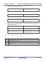
(5) if statements
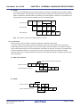
When executing the same processing to multiple cases with an if-else combination, if using a separate set of conditions would make the "multiple cases" combine into one case, then combine them.
This will delete redundant parts.
In the example below, if the conditions "the initial value of x is 0 and the values of s as well as t are either 0 or 1"
are set, the code can be changed as follows.
Before change:
After change:
if(!s){
if((s ^ t)){
if(t){
if((++u) >= v){
x = 1;
u = 0;
}
x = 1;
}else{
}
if(!t){
}
x = 1;
}
}
if(x){
if((++u) >= v){
u = 0;
}else{
x = 0;
}
}
Remarks 1.
The amount of reduction is specific to this example, and will vary case by case.
2.
As a result of changing the source, output instructions may be reduced and execution speed may
be increased.
3.
Pay attention to the following points when changing the source.
- Changing the source causes the state of register usage to change. It is therefore possible that in
unintended places register transfers that had up until that point remained without being optimized
may be erased or, alternatively, that optimization may become ineffective causing redundant register transfers to remain.
- By adding temporary variables, a new register for register variables may come to be used, resulting
in code for saving and restoring that register being added to the function entrance and exit.
If an assigned value is referenced immediately following its assignment statement, the part referred to is substituted by the assignment statement and combined into one.
This makes possible deletion of excess register transferring and reduction in code size.
In most cases, however, redundant register transferring is deleted by the C compiler's optimization, so the code
size would not change.
Before change:
After change:
--s;
if(--s == 0)){
if(s == 0){
:
:
}
}
R20UT0553EJ0100 Rev.1.00
Apr 01, 2011
Page 48 of 943
CubeSuite+ Ver.1.00.00
Remarks 1.
2.
CHAPTER 2 FUNCTIONS
The amount of reduction is specific to this example, and will vary case by case.
As a result of changing the source, output instructions may be reduced and execution speed may
be increased.
3.
Pay attention to the following points when changing the source.
- Changing the source causes the state of register usage to change. It is therefore possible that in
unintended places register transfers that had up until that point remained without being optimized
may be erased or, alternatively, that optimization may become ineffective causing redundant register transfers to remain.
- By adding temporary variables, a new register for register variables may come to be used, resulting
in code for saving and restoring that register being added to the function entrance and exit.
R20UT0553EJ0100 Rev.1.00
Apr 01, 2011
Page 49 of 943
CubeSuite+ Ver.1.00.00
CHAPTER 2 FUNCTIONS
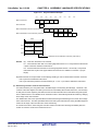
(6) if-else statements
As in the following example, if each branch destination of an if-else statement includes only statements that assign
differing values to the same variable, it is possible to reduce the code size by moving one of the branch destinations ahead of the if statement, because the else block will be erased and the jump instruction from the if the block
to after the else block is eliminated.
Before change:
After change:
if(x == 10){
s = 0;
s = 1;
if(x == 10){
}else{
s = 1;
s = 0;
}
}
Remarks 1.
The amount of reduction is specific to this example, and will vary case by case.
2.
As a result of changing the source, output instructions may be reduced and execution speed may
be increased.
3.
Pay attention to the following points when changing the source.
- Changing the source causes the state of register usage to change. It is therefore possible that in
unintended places register transfers that had up until that point remained without being optimized
may be erased or, alternatively, that optimization may become ineffective causing redundant register transfers to remain.
- By adding temporary variables, a new register for register variables may come to be used, resulting
in code for saving and restoring that register being added to the function entrance and exit.
As in the following example, if the branch destinations of if-else statements contain only return statements and
those return values are the results of the branch conditions themselves, change it to return the branch condition
expression and delete the if-else statement.
Before change:
After change:
if(s1 == s2){
return(s1 == s2);
return(1);
}
return(0);
Remarks 1.
2.
The amount of reduction is specific to this example, and will vary case by case.
As a result of changing the source, output instructions may be reduced and execution speed may
be increased.
3.
Pay attention to the following points when changing the source.
- Changing the source causes the state of register usage to change. It is therefore possible that in
unintended places register transfers that had up until that point remained without being optimized
may be erased or, alternatively, that optimization may become ineffective causing redundant register transfers to remain.
- By adding temporary variables, a new register for register variables may come to be used, resulting
in code for saving and restoring that register being added to the function entrance and exit.
If after each respective branch a function is called using differing arguments for the same function, move the function call to after the branches converge if possible.
To do this assign the differing arguments of the original function calls to temporary variables and use these temporary variables as arguments when calling the function.
R20UT0553EJ0100 Rev.1.00
Apr 01, 2011
Page 50 of 943
CubeSuite+ Ver.1.00.00
CHAPTER 2 FUNCTIONS
Before change:
After change:
if(s){
int tmp;
:
if(s){
func(0, 1, 2);
:
}else{
tmp = 2;
:
}else{
func(0, 1, 3);
:
}
tmp = 3;
}
func(0, 1, tmp);
Remarks 1.
The amount of reduction is specific to this example, and will vary case by case.
2.
As a result of changing the source, output instructions may be reduced and execution speed may
be increased.
3.
Pay attention to the following points when changing the source.
- Changing the source causes the state of register usage to change. It is therefore possible that in
unintended places register transfers that had up until that point remained without being optimized
may be erased or, alternatively, that optimization may become ineffective causing redundant register transfers to remain.
- By adding temporary variables, a new register for register variables may come to be used, resulting
in code for saving and restoring that register being added to the function entrance and exit.
In the case that after respective branches an identical assignment statement or function call exists, move it to
before the branch if possible.
If that statement's evaluation result is referenced, assign it once to a temporary variable and reference the temporary variable.
The following example is a case of a function call.
Before change:
After change:
if(x >= 0){
long
if(x > func(0, 1, 2)){
:
tmp;
tmp = func(0, 1, 2);
if(x >= 0){
}
if(x > tmp){
}else{
:
if(x < -func(0, 1, 2)){
:
}
}else{
}
if(x < -tmp){
}
:
}
}
Remarks 1.
2.
The amount of reduction is specific to this example, and will vary case by case.
As a result of changing the source, output instructions may be reduced and execution speed may
be increased.
3.
Pay attention to the following points when changing the source.
- Changing the source causes the state of register usage to change. It is therefore possible that in
unintended places register transfers that had up until that point remained without being optimized
R20UT0553EJ0100 Rev.1.00
Apr 01, 2011
Page 51 of 943
CubeSuite+ Ver.1.00.00
CHAPTER 2 FUNCTIONS
may be erased or, alternatively, that optimization may become ineffective causing redundant register transfers to remain.
- By adding temporary variables, a new register for register variables may come to be used, resulting
in code for saving and restoring that register being added to the function entrance and exit.
In the case that after respective branches an identical assignment statement or function call exists, if it cannot be
moved to before the branch but can be moved to after the merge, move it to after the merge.
The following example is an assignment statement case.
Before change:
After change:
if(tmp & MASK){
if(tmp & MASK){
:
:
j++;
}else{
}else{
:
:
}
j++;
j++;
}
Remarks 1.
2.
The amount of reduction is specific to this example, and will vary case by case.
As a result of changing the source, output instructions may be reduced and execution speed may
be increased.
3.
Pay attention to the following points when changing the source.
- Changing the source causes the state of register usage to change. It is therefore possible that in
unintended places register transfers that had up until that point remained without being optimized
may be erased or, alternatively, that optimization may become ineffective causing redundant register transfers to remain.
- By adding temporary variables, a new register for register variables may come to be used, resulting
in code for saving and restoring that register being added to the function entrance and exit.
R20UT0553EJ0100 Rev.1.00
Apr 01, 2011
Page 52 of 943
CubeSuite+ Ver.1.00.00
CHAPTER 2 FUNCTIONS
(7) switch/if-else statements
As in the following example, in the case where differing values are assigned to the same external variable at the
respective branch destinations of a switch statement or an if-else statement, it is possible to reduce code size by
assigning the values to a temporary variable at each branch and then reassigning the temporary variable value
back to the original external variable after the branches merge.
This is because, assigning to an external variable requires a memory store instruction (4 bytes) because external
variables are rarely allocated to registers, while in most cases assigning to a temporary variable uses a register
transfer (2 bytes).
In the following example s is an external variable.
Before change:
After change:
switch(x){
int tmp;
case
0:
:
s = 0;
if(x == 0){
break;
case
tmp = 0;
1:
}else if (x == 1){
s = 0x5555;
break;
case
tmp = 0x5555;
}else if(x == 2){
2:
tmp = 0xAAAA;
s = 0xAAAA;
}else if(x == 3) {
break;
case
tmp = 0xFFFF;
3:
}else{
s = 0xFFFF;
}
goto
label;
}
s = tmp;
label:
Remarks 1.
2.
The amount of reduction is specific to this example, and will vary case by case.
As a result of changing the source, output instructions may be reduced and execution speed may
be increased.
3.
Pay attention to the following points when changing the source.
- Changing the source causes the state of register usage to change. It is therefore possible that in
unintended places register transfers that had up until that point remained without being optimized
may be erased or, alternatively, that optimization may become ineffective causing redundant register transfers to remain.
- By adding temporary variables, a new register for register variables may come to be used, resulting
in code for saving and restoring that register being added to the function entrance and exit.
R20UT0553EJ0100 Rev.1.00
Apr 01, 2011
Page 53 of 943
CubeSuite+ Ver.1.00.00
CHAPTER 2 FUNCTIONS
(8) for/while statements
The CA850 generates condition judgment expressions twice for loops that begin with condition judgment expressions such as for and while
This type of change to loop format is executed at the front end (parsing part), which is the C compiler's first phase.
This is because the first condition judgment is commonly deleted by subsequent optimization, and changing the
code in this way is advantageous with regards to increasing execution speed.
However, in cases where the first condition judgment is not deleted, changing the code in this way creates redundancy with regards to code size.
[for loop]
Before change:
After change:
for(statement 1; expression 2; statement
3){
statement 1;
if(expression 2){
loop body
do{
}
loop body
statement 3;
}while(expression 2);
}
[while loop]
Before change:
After change:
while(expression 1){
if(expression 1){
loop body
do{
}
loop body
}while(expression 1);
}
Therefore, when the first time condition judgment expression is not deleted by optimization it is possible to reduce
the number of condition judgments to one by changing the loop to one composed with goto as follows.
[for loop]
statement 1;
loop_bgn:
if(! expression 2) goto loop_end;
loop body
statement 3;
goto
loop_bgn;
loop_end:
R20UT0553EJ0100 Rev.1.00
Apr 01, 2011
Page 54 of 943
CubeSuite+ Ver.1.00.00
CHAPTER 2 FUNCTIONS
[while loop]
loop_bgn:
if(! expression 1) goto loop_end;
loop body
goto loop_bgn;
loop_end:
Before change:
After change:
for(i = 0; i < s; ++i){
array[i] = array[i+1];
}
i = 0;
bgn_loop:
if(i >= s) goto end_loop;
array[i] = array[i+1];
++i;
goto bgn_loop;
end_loop:
Remarks 1.
2.
The amount of reduction is specific to this example, and will vary case by case.
As a result of changing the source, output instructions may be reduced and execution speed may
be increased.
3.
Pay attention to the following points when changing the source.
- Changing the source causes the state of register usage to change. It is therefore possible that in
unintended places register transfers that had up until that point remained without being optimized
may be erased or, alternatively, that optimization may become ineffective causing redundant register transfers to remain.
- By adding temporary variables, a new register for register variables may come to be used, resulting
in code for saving and restoring that register being added to the function entrance and exit.
(9) Functions with no return values
Define functions with no return values as "void."
R20UT0553EJ0100 Rev.1.00
Apr 01, 2011
Page 55 of 943
CubeSuite+ Ver.1.00.00
2.7.2
CHAPTER 2 FUNCTIONS
Reducing variable area with variable definition method
This section explains reducing variable area with the variable definition method.
(1) Variable signs
With the V850 microcontrollers, byte data and halfword data are sign-extended to word length, depending on the
value of their most significant bit, when they are loaded from memory to registers.
Consequently, the mask code of the higher bits may be generated when an operation on unsigned char or
unsigned short type data is performed (but it will not be generated in an operation in the case that the data is
already in the register).
Please use word data whenever possible.
When using byte data and halfword data, please use them in signed format.
Remarks 1.
The V850E supports unsigned load instructions.
Because of this, sign-extension will not occur, and mask code will not be generated.
2.
In the case of a program where word data cannot be used and mask code ends up being generated, it is possible to reduce code size by using the mask register function.
(2) Variable format
Because by ANSI-C specifications variables in short integer ((unsigned) short and (unsigned) char) formats are
expanded to int format or unsigned int format during operation, many format change instructions are generated
with respect to programs that use these variables (particularly in cases where these variables are allocated to registers).
Since making them (unsigned) int format makes this format change unnecessary, the code size is reduced.
Particularly with respect to stack intervals that are relatively easy to allocate to registers, it is recommended to use
(unsigned) int format as much as possible.
Before change:
After change:
unsigned char i;
int i;
:
:
for(i = 0; i < 4; i++){
for(i = 0; i < 4; i++){
array[2 + i] = *(p + i);
}
array[2 + i] = *(p + i);
}
Remarks 1.
2.
The amount of reduction is specific to this example, and will vary case by case.
As a result of changing the source, output instructions may be reduced and execution speed may
be increased.
3.
Pay attention to the following points when changing the source.
- Changing the source causes the state of register usage to change. It is therefore possible that in
unintended places register transfers that had up until that point remained without being optimized
may be erased or, alternatively, that optimization may become ineffective causing redundant register transfers to remain.
- By adding temporary variables, a new register for register variables may come to be used, resulting
in code for saving and restoring that register being added to the function entrance and exit.
In such a case, the code size will increase by the save/restore code amount (8 bytes).
R20UT0553EJ0100 Rev.1.00
Apr 01, 2011
Page 56 of 943
CubeSuite+ Ver.1.00.00
CHAPTER 2 FUNCTIONS
(3) Allocating and referencing automatic variables
As in the following example, if there is a time interval between when a value is assigned to a stack variable and
when that value is actually referenced, during that interval a register is occupied and the chance for other variables
to be allocated to registers decreases.
In such a case, changing the value assignment to immediately before it is actually referenced increases the chance
for other variables to be allocated to registers increases, decreases memory access, and decreases the code size.
Before change:
After change:
int i = 0, j = 0, k = 0, m = 0;
int i, j, k, m;
/*There is a function call in this
interval*/
:
i = 0;
/*These variables are not used*/
j = 0;
while((k & 0xFF) != 0xFF){
k = 0;
k = s1;
m = 0;
if(k & MASK){
while((k & 0xFF) != 0xFF){
if(m != 1){
k = s1;
s2 += 2;
if(k & MASK){
m = 1;
if(m != 1){
array[15+i+j] = 0xFF;
s2 += 2;
j++;
m = 1;
}
array[15+i+j] = 0xFF;
}
j++;
}
}
:
}
}
:
Remarks 1.
2.
The amount of reduction is specific to this example, and will vary case by case.
As a result of changing the source, output instructions may be reduced and execution speed may
be increased.
3.
Pay attention to the following points when changing the source.
- Changing the source causes the state of register usage to change. It is therefore possible that in
unintended places register transfers that had up until that point remained without being optimized
may be erased or, alternatively, that optimization may become ineffective causing redundant register transfers to remain.
- By adding temporary variables, a new register for register variables may come to be used, resulting
in code for saving and restoring that register being added to the function entrance and exit.
In such a case, the code size will increase by the save/restore code amount (8 bytes).
R20UT0553EJ0100 Rev.1.00
Apr 01, 2011
Page 57 of 943
CubeSuite+ Ver.1.00.00
CHAPTER 2 FUNCTIONS
(4) Variable types and order of definition
It is best to perform definitions in groups beginning with long data length values.
With the V850 microcontroller, word data in formats such as int format must be aligned to word boundaries, and
halfword data in formats such as short format must be aligned to halfword boundaries.
Due to this, source such as the following causes padding areas to be generated for alignment.
char
High position
c = 'c';
short s = 0;
int
i = 1;
char
d = 'b';
int
j = 2;
j
-
d
i
s
-
c
Low position
In order to avoid the generation of such padding areas, define definitions of variables and structure members
grouped by format beginning with longer data lengths.
int
i = 1;
int
j = 2;
short s = 0;
char
c = 'a';
char
d = 'b';
High position
d
c
s
j
i
Low position
R20UT0553EJ0100 Rev.1.00
Apr 01, 2011
Page 58 of 943
CubeSuite+ Ver.1.00.00
2.8
CHAPTER 2 FUNCTIONS
Accelerating Processing
This section explains accelerating processing.
2.8.1
Accelerate processing with description method
This section explains accelerate processing with the description method.
(1) Loop processing pointer
A variable that controls a loop as in the example below is called an induction variable.
"Deleting the induction variable" refers to optimization that deletes the induction variable by using a different variable to control the loop.
The CA850 includes this optimization, but because applicable conditions are limited, not all cases are able to be
optimized.
By modifying the program in the following manner, this optimization can be performed "manually".
In the lines below, induction variable i is deleted through the use of temporary variable (pointer) p.
Before change:
After change:
int i;
const unsigned short
for(i = 0; *(table + i) != NULL; ++i){
for(p = table; *p != NULL; ++p){
if((*(table + i) & 0xFF) == x){
*p;
if((*p & 0xFF) == x){
return(*p & 0xFF00);
return(*(table + i) & 0xFF00);
}
}
}
}
Remarks 1.
2.
The amount of reduction is specific to this example, and will vary case by case.
As a result of changing the source, output instructions may be reduced and execution speed may
be increased.
3.
Pay attention to the following points when changing the source.
- Changing the source causes the state of register usage to change. It is therefore possible that in
unintended places register transfers that had up until that point remained without being optimized
may be erased or, alternatively, that optimization may become ineffective causing redundant register transfers to remain.
- By adding temporary variables, a new register for register variables may come to be used, resulting
in code for saving and restoring that register being added to the function entrance and exit.
In such a case, the code size will increase by the save/restore code amount (8 bytes).
(2) Auto variable declaration
Keep the number of auto variables to within ten; of preferably to six or seven.
Auto variables are assigned to registers.
The CA850 allows a total of 20 registers, 10 work registers and 10 register variable registers, to be used for variables (in the 32-bit register mode).
It is recommended to use many auto variables if processing in one function takes time.
If the processing does not take much time, use only the 10 work registers whenever possible.
The register variable registers require overhead when they are saved or restored.
The C compiler automatically judges whether or not to use register variables.
Therefore, use six to seven registers for auto variables and leave three or four to be able to be used for work by the
C compiler.
R20UT0553EJ0100 Rev.1.00
Apr 01, 2011
Page 59 of 943
CubeSuite+ Ver.1.00.00
CHAPTER 2 FUNCTIONS
(3) Function arguments
Four argument registers, r6 to r9, are available.
If the number of arguments is five or more, the stack is used for the fifth and subsequent arguments.
Therefore, keep the number of arguments to within four whenever possible.
If five or more arguments must be used, pass the arguments using the pointer of a structure.
R20UT0553EJ0100 Rev.1.00
Apr 01, 2011
Page 60 of 943
CubeSuite+ Ver.1.00.00
2.9
CHAPTER 2 FUNCTIONS
Compiler and Assembler Mutual References
This section explains compiler and assembler mutual references.
2.9.1
Mutually referencing variables
This section explains mutually referencing variables.
(1) Reference a variable defined in C language
Define extern when referencing an external variable defined in a C language program from an assembly language
routine.
Prefix "_" (an underscore) to a variable defined in an assembly language routine.
Example C source
extern void subf ( void );
char c = 0 ;
int i = 0 ;
void main ( void ) {
subf ( );
}
Example Assembler source
.globl
_subf
.extern _c
.extern _i
.text
.align
4
_subf :
mov
4, r10
st.b
r10, $_c
mov
7, r10
st.w
r10, $_i
jmp [lp]
R20UT0553EJ0100 Rev.1.00
Apr 01, 2011
Page 61 of 943
CubeSuite+ Ver.1.00.00
CHAPTER 2 FUNCTIONS
(2) Reference a variable defined in assembly language
Define extern when referencing in a C language routine an external variable defined in an assembly language program.
Prefix "_" (an underscore) to a variable defined in an assembly language routine.
Example C source
extern char c ;
extern int i ;
void subf ( void ) {
c = 'A' ;
i = 4 ;
}
Example Assembler source
.globl _c
.globl _i
.sbss
.lcomm _i, 4, 4
.lcomm _c, 1, 1
R20UT0553EJ0100 Rev.1.00
Apr 01, 2011
Page 62 of 943
CubeSuite+ Ver.1.00.00
2.9.2
CHAPTER 2 FUNCTIONS
Mutually referencing functions
This section explains mutually referencing functions.
(1) Reference a function defined in C language
Note the following points when calling a function described in C language from an assembly language routine.
- Stack frame
Code is generated on the assumption that the stack pointer (sp) always indicates the lowest address of the
stack frame. Therefore, set sp so that it indicates the higher address of an unused area of the stack area
when execution branches from an assembler function to a C function.
- Work register
Values of the register variable registers before and after a C function is called are retained, but the values of
the work registers are not. Therefore, do not leave a value that must be retained assigned to a work register.
- Return address to return to assembler function
Code is generated on the assumption that the return address of a function is stored in link pointer lp (r31).
When execution branches to a C function, therefore, the return address of the function must be stored in lp.
(2) Reference a function defined in assembly language
Note the following points when calling an assembly language routine from a function described in C language.
- Identifier
Prefix "_" to the name.
- Stack frame
Code is output based on the assumption that the stack pointer (sp) always indicates the lowest address of the
stack frame. Therefore, the address area lower than the address indicated by sp can be freely used in the
assembler function after branching from a C language source to an assembler function. Conversely, if the
contents of the higher address area are changed, the area used by a C function may be lost and the subsequent operation cannot be guaranteed. To avoid this, change sp at the beginning of the assembler function
before using the stack.
At this time, however, make sure that the value of sp is retained before and after calling.
- Register variable register
When using a register variable register in an assembler function, make sure that the register value is retained
before and after the assembler function is called. In other words, save the value of the register variable register before calling the assembler function, and restore the value after calling.
- Return address to C language function
Code is generated on the assumption that the return address of a function is stored in link pointer lp (r31).
When execution branches to an assembler function, the return address of the function is stored in lp. Execute
the jmp [lp] instruction to return to a C function.
R20UT0553EJ0100 Rev.1.00
Apr 01, 2011
Page 63 of 943
CubeSuite+ Ver.1.00.00
CHAPTER 3 COMPILER LANGUAGE SPECIFICATIONS
CHAPTER 3 COMPILER LANGUAGE SPECIFICATIONS
This chapter explains language specifications supported by the CA850.
3.1
Basic Language Specifications
The CA850 supports the language specifications stipulated by the ANSI standards. These specifications include items
that are stipulated as processing definitions. This chapter explains the language specifications of the items dependent on
the processing system of the micro processors for V850 microcontrollers.
The differences between when options strictly conforming to the ANSI standards are used and when those options are
not used are also explained.
See "3.2 Extended Language Specifications" for extended language specifications explicitly added by CA850.
3.1.1
Processing system dependent Items
This section explains items dependent on processing system in the ANSI standards.
(1) Data types and sizes
The byte order in a word (4 bytes) is "from least significant to most significant byte" Signed integers are expressed
by 2's complements. The sign is added to the most significant bit (0 for positive or 0, and 1 for negative).
- The number of bits of 1 byte is 8.
- The number of bytes, byte order, and encoding in an object files are stipulated below.
Table 3-1. Data Types and Sizes
Data Types
Sizes
char
1 byte
short
2 bytes
int, long, float, double
4 bytes
pointer
Same as unsigned int
(2) Translation stages
The ANSI standards specify eight translation stages (known as "phases") of priorities among syntax rules for translation. The arrangement of "non-empty white space characters excluding line feed characters" which is defined as
processing system dependent in phase 3 "Decomposition of source file into preprocessing tokens and white space
characters" is maintained as it is without being replaced by single white space character.
(3) Diagnostic messages
When syntax rule violation or restriction violation occurs on a translation unit, the compiler outputs as error message containing source file name and (when it can be determined) the number of line containing the error. These
error messages are classified into three types: "warning", "fatal error", and "other error" messages.
R20UT0553EJ0100 Rev.1.00
Apr 01, 2011
Page 64 of 943
CubeSuite+ Ver.1.00.00
CHAPTER 3 COMPILER LANGUAGE SPECIFICATIONS
(4) Free standing environment
(a) The name and type of a function that is called on starting program processing are not stipulted in a
free-standing environmentNote. Therefore, it is dependent on the user-own coding and target system.
Note Environment in which a C Language source program is executed without using the functions of the
operating system.
In the ANSI Standard two environments are stipulated for execution environment: a free-standing environment and a host environment. The CA850 does not supply a host environment at present.
(b) The effect of terminating a program in a free-standing environment is not stipulated. Therefore, it is
dependent on the user-own coding and target system.
(5) Program execution
The configuration of the interactive unit is not stipulated.
Therefore, it is dependent on the user-own coding and target system.
(6) Character set
The values of elements of the execution environment character set are ASCII codes.
(7) Multi-byte characters
Multi-byte characters are not supported by character constants.
However, Japanese description in comments and character strings is supported.
(8) Significance of character display
The values of expanded notation are stipulated as follows.
Table 3-2. Expanded Notation and Meaning
Expanded Notation
Value(ASCII)
Meaning
\a
07
Alert (Warning tone)
\b
08
Backspace
\f
0C
Form feed (New Page)
\n
0A
New line (Line feed)
\r
0D
Carriage return (Restore)
\t
09
Horizontal tab
\v
0B
Vertical tab
R20UT0553EJ0100 Rev.1.00
Apr 01, 2011
Page 65 of 943
CubeSuite+ Ver.1.00.00
CHAPTER 3 COMPILER LANGUAGE SPECIFICATIONS
(9) Translation Limit
The limit values of translation are explained below.
The values marked with * are guaranteed values. These values may be exceeded in some cases, but the operation is not guaranteed.
Table 3-3. Translation Limit Values
Contents
Number of nesting levels of compound statements, repetitive control structures, and selective
Limit values
127
control structures
(However, dependent on the number of "case" labels)
Number of nesting levels of condition embedding
255
Number of pointers, arrays, and function declarators (in any combination) qualifying one arith-
16
metic type, structure type, union type, or incomplete type in one declaration
Number of nesting levels enclosed by parentheses in a complete declarator
255*
Number of nesting levels of an expression enclosed by parentheses in a complete expression
255*
Valid number of first characters in a macro name
1023
Valid number of first characters of an external identifier
1022
Valid number of first characters in an internal identifier
1023
Number of identifiers having an external identifier in one translation unit and the valid block range
4095*
declared in one basic block
Number of macro identifiersNote simultaneously defined in one translation unit
2047
Number of parameters in one function definition and number of actual arguments in one function
255
call
Number of parameters in one macro definition
127
Number of actual arguments in one macro call
127
Number of characters in one logical source line
32768
One character string constant after concatenation, or number of characters in a wide character
32766
string constant
Number of nesting levels for include (#include) files
50
Number of "case" labels for one "switch" statement
1025
(including those nested, if any)
Number of members of a single structure or single union
1023*
Number of enumerate constants in a single enumerate type
1023*
Number of nesting levels of a structure or union definition in the arrangement of a single structure
63*
declaration
Note The upper limit of the macro identifier can be changed by a C compiler option (-Xm).
R20UT0553EJ0100 Rev.1.00
Apr 01, 2011
Page 66 of 943
CubeSuite+ Ver.1.00.00
CHAPTER 3 COMPILER LANGUAGE SPECIFICATIONS
(10) Quantitative limit
(a) The limit values of the general integer types (limits.h file)
The limits.h file specifies the limit values of the values that can be expressed as general integer types (char
type, signed/unsigned integer type, and enumerate type).
Because multibyte characters are not supported, MB_LEN_MAX does not have a corresponding limit. Consequently, it is only defined with MB_LEN_MAX as 1.
If a -Xchar=unsigned option of the CA850 is specified, CHAR_MIN is 0, and CHAR_MAX takes the same
value as UCHAR_MAX.
The limit values defined by the limits.h file are as follows.
Table 3-4. Limit Values of General Integer Type (limits.h File)
Name
CHAR_BIT
Value
+8
Meaning
The number of bits (= 1 byte) of the minimum object not
in bit field
SCHAR_MIN
-128
Minimum value of signed char
SCHAR_MAX
+127
Maximum value of signed char
UCHAR_MAX
+255
Maximum value of unsigned char
CHAR_MIN
-128
Minimum value of char
CHAR_MAX
+127
Maximum value of char
SHRT_MIN
-32768
Minimum value of short int
SHRT_MAX
+32767
Maximum value of short int
USHRT_MAX
+65535
Maximum value of unsigned short int
INT_MIN
-2147483648
Minimum value of int
INT_MAX
+2147483647
Maximum value of int
UINT_MAX
+4294967295
Maximum value of unsigned int
LONG_MIN
-2147483648
Minimum value of long int
LONG_MAX
+2147483647
Maximum value of long int
ULONG_MAX
+4294967295
Maximum value of unsigned long int
(b) The limit values of the floating-point type (float.h file)
The limit values related to characteristics of the floating-point type are defined in float.h file.
The limit values defined by the float.h file are as follows.
Table 3-5. Definition of Limit Values of Floating-point Type (float.h File)
Name
FLT_ROUNDS
Value
+1
Meaning
Rounding mode for floating-point addition.
1 for the V850 microcontrollers (rounding in the nearest
direction).
FLT_RADIX
+2
FLT_MANT_DIG
+24
DBL_MANT_DIG
Radix of exponent (b)
Number of numerals (p) with FLT_RADIX of floatingpoint mantissa as base
LDBL_MANT_DIG
R20UT0553EJ0100 Rev.1.00
Apr 01, 2011
Page 67 of 943
CubeSuite+ Ver.1.00.00
CHAPTER 3 COMPILER LANGUAGE SPECIFICATIONS
Name
FLT_DIG
Value
+6
Meaning
Number of digits of a decimal numberNote 1 (q) that can
round a decimal number of q digits to a floating-point
DBL_DIG
number of p digits of the radix b and then restore the
LDBL_DIG
FLT_MIN_EXP
decimal number of q
-125
Minimum negative integer (emin) that is a normalized
floating-point number when FLT_RADIX is raised to the
DBL_MIN_EXP
power of the value of FLT_RADIX minus 1.
LDBL_MIN_EXP
FLT_MIN_10_EXP
-37
Minimum negative integerlog10bemin-1 that falls in the
range of a normalized floating-point number when 10 is
DBL_MIN_10_EXP
raised to the power of its value.
LDBL_MIN_10_EXP
FLT_MAX_EXP
+128
Maximum integer (emax) that is a finite floating-point
number that can be expressed when FLT_RADIX is
DBL_MAX_EXP
raised to the power of its value minus 1.
LDBL_MAX_EXP
FLT_MAX_10_EXP
+38
Maximum value of finite floating-point numbers that can
be expressed
DBL_MAX_10_EXP
(1 - b-p) * bemax
LDBL_MAX_10_EXP
FLT_MAX
3.40282347E + 38F
Maximum value of finite floating-point numbers that can
be expressed
DBL_MAX
(1 - b-p) * bemax
LDBL_MAX
FLT_EPSILON
1.19209290E - 07F
specified floating-point number type and the lowest
DBL_EPSILON
value which is greater than 1.
b1 - p
LDBL_EPSILON
FLT_MIN
DifferenceNote2 between 1.0 that can be expressed by
1.17549435E - 38F
Minimum value of normalized positive floating-point
number
DBL_MIN
bemin - 1
LDBL_MIN
Notes 1.
DBL_DIG and LDBL_DIG are 10 or more in the ANSI standards but are 6 in the V850 microcontrollers because both the double and long double types are 32 bits.
2.
DBL_EPSILON and LDBL_EPSILON are 1E-9 or less in the ANSI standards, but 1.19209290E07F in the V850 microcontrollers.
(11) Identifier
An external name must consist of up to 1022 characters and must be able to be identified uniformly.
Uppercase and lowercase characters are distinguished.
R20UT0553EJ0100 Rev.1.00
Apr 01, 2011
Page 68 of 943
CubeSuite+ Ver.1.00.00
CHAPTER 3 COMPILER LANGUAGE SPECIFICATIONS
(12) char type
A char type with no type specifier (signed, unsigned) specified is treated as a signed integer as the default assumption.
However, a simple char type can be treated as an unsigned integer by specifying the - Xchar=unsigned option of
the CA850.
The types of those that are not included in the character set of the source program required by the ANSI standards
(escape sequence) is converted for storage, in the same manner as when types other than char type are substituted for a char type.
char
c = '\777';
/* Value of c is -1 */
(13) Floating-point constants
The floating-point constants conform to IEEE754Note.
Note IEEE:Institute of Electrical and Electronics Engineers
Moreover,IEEE754 is a standard to unify specifications such as the data format and numeric range in
systems that handle floating-point operations.
(14) Character constants
(a) Both the character set of the source program and the character set in the execution environment are
basically ASCII codes, and correspond to members having the same value.
However, for the character set of the source program, character codes in Japanese can be used (see
"(8) Significance of character display").
(b) The last character of the value of an integer character constant including two or more characters is
valid.
(c) A character that cannot be expressed by the basic execution environment character set or escape
sequence is expressed as follows.
<1> An octal or hexadecimal escape sequence takes the value indicated by the octal or hexadecimal
notation
\777
511
<2> The simple escape sequence is expressed as follows.
\'
'
\"
"
\?
?
\\
\
<3> Values of \a, \b, \f, \n, \r, \t, \v are same as the values explained in "(8) Significance of character
display".
(d) Character constants of multi byte characters are not supported.
R20UT0553EJ0100 Rev.1.00
Apr 01, 2011
Page 69 of 943
CubeSuite+ Ver.1.00.00
CHAPTER 3 COMPILER LANGUAGE SPECIFICATIONS
(15) Character string
A character string can be described in Japanese.
The default character code is Shift JIS.
A character code in input source file can be selected by using the -Xk option of the CA850.
However, if n or none is specified, character code is not guaranteed.
[Option specification]
-Xk=[e | euc | n | none | s | sjis]
A character code in output source file can be changed by using the -Xkt option of the CA850. However, if n or
none is specified, character code cannot be changed.
[Option specification]
-Xkt=[e | euc | n | none | s | sjis]
(16) Header file name
The method to reflect the string in the two formats (< > and " ") of a header file name on the header file or an
external source file name is stipulated in "(33) Loading header file".
(17) Comment
A comment can be described in Japanese. The character code is the same as the character string in "(15) Character string".
(18) Signed constants and unsigned constants
If the value of a general integer type is converted into a signed integer of a smaller size, the higher bits are truncated and a bit string image is copied.
If an unsigned integer is converted into the corresponding signed integer, the internal representation is not
changed.
(19) Floating-points and general integers
If the value of a general integer type is converted into the value of a floating-point type, and if the value to be converted is within a range that can be expressed but not accurately, the result is rounded to the closest expressible
value.
When the result is just a middle value, it can be rounded to the even number (with the least significant bit of the
mantissa being 0).
(20) double type and float type
In the CA850, a double type is expressed as a floating-point number in the same manner as a float type, and is
treated as 32-bit (single-precision) data.
(21) Signed type in operator in bit units
The characteristics of the shift operator conform to the stipulation in"(27) Shift operator in bit units" .
The other operators in bit units for signed type are calculated as unsigned values (as in the bit imag.
R20UT0553EJ0100 Rev.1.00
Apr 01, 2011
Page 70 of 943
CubeSuite+ Ver.1.00.00
CHAPTER 3 COMPILER LANGUAGE SPECIFICATIONS
(22) Members of structures and unions
If the value of a member of a union is stored in a different member, it is stored according to an alignment condition.
Therefore, the members of that union are accessed according to the alignment condition (see "(6) Structure type"
and "(7) Union type").
In the case of a union that includes a structure sharing the arrangement of the common first members as a member, the internal representation is the same, and the result is the same even if the first member common to any
structure is referred.
(23) sizeof operator
The value resulting from the "sizeof" operator conforms to the stipulation related to the bytes in an object in"(1)
Data types and sizes".
For the number of bytes in a structure and union, it is byte including padding area.
(24) Cast operator
When a pointer is converted into a general integer type, the required size of the variable is the same as the size of
the int type. The bit string is saved as is as the conversion result.
Any integer can be converted by a pointer. However, the result of converting an integer smaller than an int type is
expanded according to the type.
(25) Division/remainder operator
The result of the division operator ("/") when the operands are negative and do not divide perfectly with integer division, is as follows: If either the divisor or the dividend is negative, the result is the smallest integer greater than the
algebraic quotient.
If both the divisor and the dividend are negative, the result is the largest integer less than the algebraic quotient.
If the operand is negative, the result of the "%" operator takes the sign of the first operand in the expression.
(26) Addition and subtraction operators
If two pointers indicating the elements of the same array are subtracted, the type of the result is int type, and the
size is 4 bytes.
(27) Shift operator in bit units
If E1 of "E1 >> E2" is of signed type and takes a negative value, an arithmetic shift is executed.
(28) Storage area class specifier
The storage area class specifier "register" is declared to increase the access speed as much as possible, but this
is not always effective.
R20UT0553EJ0100 Rev.1.00
Apr 01, 2011
Page 71 of 943
CubeSuite+ Ver.1.00.00
CHAPTER 3 COMPILER LANGUAGE SPECIFICATIONS
(29) Structure and union specifier
(a) A simple int type bit field without signed or unsigned appended is treated as a signed field, and the
most significant bit is treated as the sign bit. However, the simple int type bit field can be treated as an
unsigned field by specifying the -Xbitfield option (Specifying sign of simple int type bit field) of the
CA850.
(b) To retain a bit field, a storage area unit to which any address with sufficient size can be assigned can
be allocated. If there is insufficient area, however, the bit field that does not match is packed into to
the next unit according to the alignment condition of the type of the field.
(c) The allocation sequence of the bit field in unit is from lower to higher.
(d) Each member of the non-bit field of one structure or union is aligned at a boundary as follows
char, unsigned char type, and its array
Byte boundary
short, unsigned short type, and its array
Halfword boundary
Others (including pointer)
Word boundary
(30) Enumerate type specifier
The type of an enumeration specifier is signed int.
However, when the -Xenum_type=string option is specified, it is as follows
char
Treated as char
uchar
Treated as unsigned char
short
Treated as short
ushort
Treated as unsigned short
(31) Type qualifier
The configuration of access to data having a type qualified to be "volatile" is dependent upon the address (I/O port,
etc.) to which the data is mapped.
(32) Condition embedding
(a) The value for the constant specified for condition embedding and the value of the character constant
appearing in the other expressions are equal.
(b) The character constant of a single character must not have a negative value.
R20UT0553EJ0100 Rev.1.00
Apr 01, 2011
Page 72 of 943
CubeSuite+ Ver.1.00.00
CHAPTER 3 COMPILER LANGUAGE SPECIFICATIONS
(33) Loading header file
(a) A preprocessing directive in the form of "#include <character string>"
A preprocessing directive in the form of "#include <character string>" searches for a header file from the folder
specified by the -I option if "character string" does not begin with "\"Note, and then searches the \inc850 folder
with a relative path from the bin folder where the ca850 is placed.
If a header file uniformly identified is searched with a character string specified between delimiters "<" and ">",
the whole contents of the header file are replaced.
Note "/" are regarded as the delimiters of a folder.
Example
#include
<header.h>
The search order is as follows.
- Folder specified by -I
- Standard folder
(b) A preprocessing directive in the form of "#include "character string""
A preprocessing directive in the form of "#include "character string"" searches for a header file from the folder
where the source file exists, then searches specified folder (-I option) and then searches the ..\inc850 folder
via a relative path from the bin folder where the ca850 is placed.
If a header file uniformly identified is searched with a character string specified between delimiters " " "and " "
", the whole contents of the header file are replaced.
Example
#include
"header.h"
The search order is as follows.
- Folder where source file exists
- Folder specified by -I
- Standard folder
(c) The format of "#include preprocessing character phrase string"
The format of "#include preprocessing character phrase string" is treated as the preprocessing character
phrase of single header file only if the preprocessing character phrase string is a macro that is replaced to the
form of <character string> or "character string".
(d) A preprocessing directive in the form of "#include <character string>"
Between a string delimited (finally) and a header file name, the length of the alphabetic characters in the
strings is identified,
And the file name length valid in the compiler operating environment is valid.
The folder that searches a file conforms to the above stipulation.
R20UT0553EJ0100 Rev.1.00
Apr 01, 2011
Page 73 of 943
CubeSuite+ Ver.1.00.00
CHAPTER 3 COMPILER LANGUAGE SPECIFICATIONS
(34) #pragma directive
The CA850 can specify the following #pragma directives.
(a) Describing Assembler Instruction
#pragma asm
assembler instruction
#pragma endasm
Assembler directives can be described in a C language source program.
For the details of description, see "(4) Describing assembler instruction".
(b) Inline Expansion Specification
#pragma inline
function-name [, function-name ...]
A function that is expanded inline can be specified.
For the details of expansion specification, see " (8) Inline expansion".
(c) Specifying device type
#pragma cpu
device-name
Specify so that a device file defining the machine-dependent information of the device used is referred. This
function is the same as the device specification option (-cpu) of the CA850. Used when defining device in C
language source.
(d) Data or program memory allocation
#pragma section section-type ["section-name"] [begin | end]
#pragma text
["section name"] [function name]
<1> section
Allocates variables to an arbitrary section.
For details about the allocation method, see "(1) Allocation of data to section".
<2> text
A function to be allocated in a text section with an arbitrary name can be specified.
For details about the allocation specification, see "(2) Allocating functions to sections" .
(e) Peripheral I/O register name validation specification
#pragma ioreg
The peripheral I/O registers of a device are accessed by using peripheral function register names. When
programming using peripheral I/O registers names as it is, #pragma directives are needed to be specified.
(f) Interrupt/exception handler specification
R20UT0553EJ0100 Rev.1.00
Apr 01, 2011
Page 74 of 943
CubeSuite+ Ver.1.00.00
CHAPTER 3 COMPILER LANGUAGE SPECIFICATIONS
#pragma interrupt
interrupt-request-name function-name [allocation-method]
Interrupt/Exception handlers are described in C language.
For the details of description, see "(c) Describing interrupt/exception handler".
(g) Interrupt disable function specification
#pragma block_interrupt function-name
Interrupts are disabled for the entire function.
(h) Task specification
#pragma rtos_task
function-name
The task of operating on the realtime OS is described by C language.
For the details of description, see "(a) Description of task".
(i) Structure type packing specification
#pragma pack([1248])
Specifies the packing of a structure type. The packing value, which is an alignment value of the member, is
specified as the numeric value. A value of 1, 2, 4, or 8 can be specified. When the numeric value is not specified, it is by default (8)Note.
Note Alignment values "4" and "8" are treated as the same in this Version.
(35) Predefined macro names
All the following macro names are supported.
Macros not ending with "_ _ " are supplied for the sake of former C language specifications (K&R specifications).
To perform processing strictly conforming to the ANSI standards, use macros with "_ _ " before and after.
Table 3-6. List of Supported Macros
Macro name
Definition
__LINE__
Line number of source line at that point (decimal).
__FILE__
Name of assumed source file (character string constant).
__DATE__
Date of translating source file (character string constant in the form of "Mmm dd yyyy".
) Here, the name of the month is the same as that created by the asctime function stipulated by ANSI standards ( 3 alphabetic characters with only the first character is capital letter) (The first character of dd is blank if its value is less than 10).
__TIME__
Translation time of source file (character string constant having format "hh:mm:ss" similar to the time created by the asctime function).
__STDC__
Decimal constant 1 (defined when -ansi option is specified)Note
__v800
Decimal constant 1.
__v800__
R20UT0553EJ0100 Rev.1.00
Apr 01, 2011
Page 75 of 943
CubeSuite+ Ver.1.00.00
CHAPTER 3 COMPILER LANGUAGE SPECIFICATIONS
Macro name
Definition
__v850
Decimal constant 1.
__v850__
__v850e
Decimal constant 1 (defined by CA850, if V850Ex is specified as a target device).
__v850e__
__v850e2
Decimal constant 1 (defined by CA850, if V850E2 is specified as a target device).
__v850e2__
__CA850
Decimal constant 1.
__CA850__
__CHAR_SIGNED__
Decimal constant 1 (defined if signed is specified by -Xchar option and when -Xchar
option is not specified).
__CHAR_UNSIGNED__
Decimal constant 1 (defined when unsigned is specified by -Xchar option).
__DOUBLE_IS_32BITS__
Decimal constant 1.
_DOUBLE_IS_32BITS
Decimal constant 1.
CPUmacro
Decimal constant 1 of a macro indicating the target CPU. A character string indicated
by "product type specification" in the device file with "_ _ " prefixed and suffixed is
defined.
Register mode macro
Decimal constant 1 of a macro indicating the target CPU.
Macro defined with register mode is as follows.
32register mode:__reg32__
26 register mode: __reg26__
22 register mode: __reg22__
Note For the processing to be performed when the -ansi option is specified, see "3.1.2 Ansi option".
(36) Definition of special data type
NULL, size_t, and ptrdiff_t defined by stddef.h file are as follows.
Table 3-7. Definition of NULL, size_t, ptrdiff_t (stddef.h File)
NULL/size_t/ptrdiff_t
Definition
NULL
( ( void * ) 0 )
size_t
unsigned int
ptrdiff_t
int
R20UT0553EJ0100 Rev.1.00
Apr 01, 2011
Page 76 of 943
CubeSuite+ Ver.1.00.00
3.1.2
CHAPTER 3 COMPILER LANGUAGE SPECIFICATIONS
Ansi option
When ansi option is specified by CA850, process strictly conforming to ANSI standards is executed.
The differences between when -ansi options are specified and when not specified are as follows.
Table 3-8. Processing When -ansi Option Strictly Conforming to Language Specifications is Specified
Item
With -ansi Specification
Without -ansi Specification
Trigraph series
Trigraph series is replaced.
Not replaced.
Bit field
ErrorNote 1
Outputs warning message and permits.
occurs if type other than int is speci-
fied for bit field.
Argument scope
Multiple defined error occurs if automatic vari-
Outputs warning message and validates
able having same name as argument of function
automatic variable.
is declared.
Pointer substitution 1
Error occurs if the numeric value of pointer type
Outputs warning message, casts, and substi-
is substituted into general integer typeNote 2 vari-
tutes.
able.
Pointer substitution 2
Error occurs if pointers indicating different types
Outputs warning message and permits.
are substituted for each other.
Type conversion
Error occurs if conversion into pointer of array
Outputs warning message and permits.
that is not left-member value is performed.
Comparison operator
Error occurs if arithmatic type variable and
Outputs warning message and permits.
pointer are compared.
Conditional operator
Error occurs if both second and third expres-
Outputs warning message, casts, and substi-
sions are not general integer type, same struc-
tutes.
ture, same union, or numeric value of pointer
type to type same as substitution destination.
# line number
Error occurs.
Treated in same manner as "#line line number".Note 3
Character # in middle of
Error occurs if character # appears in the middle
line
of the line.
_asm
Outputs warning message and handles as func-
Outputs warning message and permits.
Treated as assembler insertionNote 4.
tion call.
However, _ _ asm is valid.
__STDC__
Binary Constants
Defines value as macro with value 1 .
Does not define.
Error occurs if "0b" or "0B" is followed by one or
Treats "0b" or "0B" followed by one or more
more "0" or "1".
"0" or "1" as a binary constant.
Notes 1.
Normal error beginning with "E". The same applies hereafter.
2.
char type, signed/unsigned integer type, and enumerate type.
3.
See the ANSI standards.
4.
See "(4) Describing assembler instruction".
R20UT0553EJ0100 Rev.1.00
Apr 01, 2011
Page 77 of 943
CubeSuite+ Ver.1.00.00
3.1.3
CHAPTER 3 COMPILER LANGUAGE SPECIFICATIONS
Internal representation and value area of data
This section explains the internal representation and value area of each type for the data handled by the CA850.
(1) Integer type
(a) Internal representation
The leftmost bit in an area is a sign bit with a signed type (type declared without "unsigned"). The value of a
signed type is expressed as 2' s complement.
If -Xchar=unsigned is specified, however, a char type specified without "signed" or "unsigned" is assumed to
be unsigned.
Figure 3-1. Internal Representation of Integer Type
char(no sign bit for unsigned)
7
0
Short (no sign bit for unsigned)
15
0
int, long (no sign bit for unsigned)
31
0
(b) Value area
Table 3-9. Value Area of Integer Type
Type
Value Area
charNote
-128 to +127
short
-32768 to +32767
int
-2147483648 to +2147483647
long
-2147483648 to +2147483647
unsigned char
0 to 255
unsigned short
0 to 65535
unsigned int
0 to 4294967295
unsigned long
0 to 4294967295
Note The value area is 0 to 255, if "-Xchar=unsigned" is specified by the CA850.
Caution
64-bit operation cannot be done by the CA850.
R20UT0553EJ0100 Rev.1.00
Apr 01, 2011
Page 78 of 943
CubeSuite+ Ver.1.00.00
CHAPTER 3 COMPILER LANGUAGE SPECIFICATIONS
(2) Floating-point type
(a) Internal representation
Internal Representation of floating-point data type conforms to IEEE754Note. The leftmost bit in an area of a
sign bit. If the value of this sign bit is 0, the data is a positive value; if it is 1, the data is a negative value.
A double type is a floating-point representation same as a float type, and is handled as 32-bit (single- precision) data.
Note IEEE: Institute of Electrical and Electronics Engineers
IEEE754 is a standard to unify specifications such as the data format and numeric range in systems
that handle floating-point operations.
Figure 3-2. Internal Representation of Floating-Point Type
float, double
S
E
M
31
0
23 22
S: Sign bit of mantissa
E: Exponent (8 bits)
M: Mantissa (23 bits)
(b) Value area
Table 3-10. Value Area of Floating-Point Type
Type
Value Area
float, double
1.18 x 10
-38
38
to 3.40 x 10
(3) Pointer type
(a) Internal representation
The internal representation of a pointer type is the same as that of an unsigned int type.
Figure 3-3. Internal Representation of Pointer Type
31
0
(4) Enumerate type
(a) Internal representation
The internal representation of an enumerate type is the same as that of a signed int type. The leftmost bit in
an area of a sign bit.
R20UT0553EJ0100 Rev.1.00
Apr 01, 2011
Page 79 of 943
CubeSuite+ Ver.1.00.00
CHAPTER 3 COMPILER LANGUAGE SPECIFICATIONS
Figure 3-4. Internal Representation of Enumerate Type
31
0
When the -Xenum_type=string option is specified, see "(30) Enumerate type specifier".
(5) Array type
(a) Internal representation
The internal representation of an array type arranges the elements of an array in the form that satisfies the
alignment condition(alignment) of the elements
Example
char
a[8] = {1, 2, 3, 4, 5, 6, 7, 8};
The internal representation of the array shown above is as follows.
Figure 3-5. Internal Representation of Array Type
7
0 7
0 7
0 7
0 7
0 7
0 7
0 7
0
(6) Structure type
(a) Internal representation
The internal representation of a structure type arranges the elements of a structure in a form that satisfies the
alignment condition of the elements.
Example
struct{
short
s1;
int
s2;
char
s3;
long
s4;
}tag;
The internal representation of the structure shown above is as follows.
Figure 3-6. Internal Representation of Structure Type
s4
31
s3
0 31
8 7 0 31
s2
s1
0 31
16 15
0
For the internal representation when the structure type packing function is used, see "(11) Structure type
packing".
R20UT0553EJ0100 Rev.1.00
Apr 01, 2011
Page 80 of 943
CubeSuite+ Ver.1.00.00
CHAPTER 3 COMPILER LANGUAGE SPECIFICATIONS
(7) Union type
(a) Internal representation
A union is considered as a structure whose members all start with offset 0 and that has sufficient size to
accommodate any of its members. The internal representation of a union type is like each element of the
union is placed separately at the same address.
Example
union{
int
u1;
short
u2;
char
u3;
long
u4;
}tag;
The internal representation of the union shown in the above example is as follows.
Figure 3-7. Internal Representation of Union Type
31
0
tag.u3 (1 byte)
tag.u2 (2 bytes)
tag.u1, tag.u4 (4 bytes)
(8) Bit field
(a) Internal representation
An area including the declared number of bits is reserved for a bit field. The most significant bit of the area for
a bit field declared to be of signed type is a sign bit.
The bit field declared first is allocated from the least significant bit of a word area. If the alignment condition of
the type specified in the declaration of a bit field is exceeded as a result of allocating an area that immediately
follows the area of the preceding bit field to the bit field, the area is allocated starting from a boundary that satisfies the alignment condition.
Example
struct{
unsigned int
f1:30;
int
f2:14;
unsigned int
f3:6;
}flag;
The internal representation for the bit field in the above example is as follows.
R20UT0553EJ0100 Rev.1.00
Apr 01, 2011
Page 81 of 943
CubeSuite+ Ver.1.00.00
CHAPTER 3 COMPILER LANGUAGE SPECIFICATIONS
Figure 3-8. Internal Representation of Bit Field
f2
f3
31
20 19
f1
14 13
0 31 29
0
The ANSI standards do not allow char and short types to be specified for a bit field, but CA850 allows this.
In this case, a warning message is output, and paddingNote is performed according to the alignment condition
of the specified type.
For the internal representation of bit field when the structure type packing function is used, see "(11) Structure
type packing".
Note An error occurs if -ansi is specified as an option of the CA850.
(9) Alignment condition
(a) Alignment condition for basic type
Alignment condition for basic type is as follows.
If -Xi of the CA850 is specified, however, all the arrey types are word boundaries.
Table 3-11. Alignment Condition for Basic Type
Basic Type
Alignment conditions
(unsigned) char and its array type
Byte boundary
(unsigned) short and its array type
Halfword boundary
Other basic types (including pointer)
Word boundary
(b) Alignment condition for union type
The alignment condition for the union type varies as shown in Table 3-12, depending on the maximum member size.
Table 3-12. Alignment Condition for Union Type
Maximum Member Size
Alignment conditions
2 bytes < size
Word boundary
Size <= 2 bytes
Maximum member size boundary
Here are examples of the respective cases:
Examples 1.
union
tug1{
unsigned short i; /*2 Bytes member*/
unsigned char
};
c; /*1 Bytes member */
/* The union is aligned with 2 bytes. */
R20UT0553EJ0100 Rev.1.00
Apr 01, 2011
Page 82 of 943
CubeSuite+ Ver.1.00.00
CHAPTER 3 COMPILER LANGUAGE SPECIFICATIONS
2.
union
tug2{
unsigned int
i; /*4 Byte member*/
unsigned char
};
c; /*1 Bytes member */
/* The union is aligned with 4 bytes. */
(c) Alignment condition for structure type
The alignment condition for the structure type differs as shown in Table 3-13, depending on the size of the
structure (excluding the size of the integer).
If -Xi of the CA850 is specified, however, all the structure types are word boundaries.
Table 3-13. Alignment Condition of Structure Type
Structure size
Alignment conditions
2 bytes < size
Word boundary
Size <= 2 bytes
It is either of the following depending on the size and member type.
- If member of type more than int type exists
--> Word boundary
- Other than above,if the member of the short type exists or the size is 2.
--> Halfword boundary
- If only member of char type, and the size is 1 byte.
--> Byte boundary
Here are examples of the respective cases:
Examples 1.
struct
};
SS{
int
i;
/*4 Byte member */
char
c;
/*1 Byte member*/
/* Structure is aligned with 4 bytes. */
2.
struct
int
};
BIT_I{
i1:5;
/*4 Byte member (Size is 1 byte or less)*/
/* Structure is aligned with 4 bytes because member type is int. */
3.
struct
char
};
BIT_C{
c1:5;
/*1 Byte member */
/* Structure is aligned with 1 byte. */
R20UT0553EJ0100 Rev.1.00
Apr 01, 2011
Page 83 of 943
CubeSuite+ Ver.1.00.00
CHAPTER 3 COMPILER LANGUAGE SPECIFICATIONS
4.
struct
BIT_CC{
char
c1:5;
/*1 Byte member */
char
c2:5;
/*1 Byte member*/
};
/* Structure is aligned with 2 bytes because size is 2 bytes. */
(d) Alignment condition for function argument
The alignment condition for a function argument is a word boundary.
(e) Alignment condition for executable program
The alignment condition when an executable object file is created by linking object files is a halfword boundary.
3.1.4
General-purpose registers
How the CA850 uses the general-purpose registers are as follows.
The general-purpose registers includes the following functions.
(1) Software register bank
The number of the work registers (r10 through r19) and register variable registers (r20 through r29) used can be
reduced by the -reg option of CA850 (see "3.1.6 Software register bank").
(2) Mask register function
In the 32-register mode and 22-register mode, registers r20 and r21 can be used to set a mask value (see "3.1.7
Mask register").
Table 3-14. Using General-Purpose Registers
Register
r0
Zero register
Usage
Used for operation as value of 0.
Also used to reference data located at const section (read-only
section placed in ROM area)Note.
r1
Assembler-reserved register
Used for instruction expansion by assembler.
r2 (hp)
Handler stack pointer
Reserved for system.
r3 (sp)
Stack pointer
Used to indicate beginning of stack frame.
r4 (gp)
Global pointer
Used to reference external variable.
r5 (tp)
Text pointer
Used to indicate beginning of text section (.text section)
r6-r9
Argument registers
Used to pass argument.
r10 to r19
Work register
Used as work area during operation (r10 is also used to pass
return value of function).
r20 to r29
Register variable registers
Used as an area for register variables.
r30 (ep)
Element pointer
Used to reference external variable specified to be located in
internal RAM or external RAM sectionNote.
r31 (lp)
Link pointer
Used to pass return address of function.
Note For the allocation of data to a section, see "(1) Allocation of data to section".
R20UT0553EJ0100 Rev.1.00
Apr 01, 2011
Page 84 of 943
CubeSuite+ Ver.1.00.00
3.1.5
CHAPTER 3 COMPILER LANGUAGE SPECIFICATIONS
Referencing data
How the CA850 references data are as follows.
Table 3-15. Referencing Data
Type
Referencing Method
Numeric constant
Immediate
Character string constant
Offset from global pointer (gp)
Offset from element pointer (ep)
Offset from r0
Automatic variable,Argument
Offset from stack pointer (sp)
External variable,Static variable in function
Offset from global pointer (gp)
Offset from element pointer (ep)
Offset from r0
Function address
3.1.6
Operated during execution by using offset from text pointer (tp)
Software register bank
Because the CA850 implements a register bank function by software, three register modes are provided. By specifying
these register modes efficiently, the contents of some registers do not need to be saved or restored when an interrupt
occurs or the task is switched. As a result, the processing speed can be improved. The register modes are specified by
using the register mode specification option (-reg) of CA850. This function reduces the number of registers internally
used by the CA850 on a step-by-step basis. As a result, the following effects can be expected:
- The registers not used can be used for the application program (that is, a source program in assembly language).
- The overhead required for saving and restoring registers can be reduced.
Caution
In an application program that has many variables to be allocated to registers by the CA850, the
variables so far allocated to a register are accessed from memory when a register mode has been
specified. As a result, the processing speed may drop.
(1) Register mode
Next table and next Figure show the three register modes supplied by the CA850.
Table 3-16. Register Modes Supplied by CA850
Register modes
Work Register
Register Variable Registers
32-register mode (Default)
r10 to r19
r20 to r29
26-register mode
r10 to r16
r23 to r29
22-register mode
r10 to r14
r25 to r29
R20UT0553EJ0100 Rev.1.00
Apr 01, 2011
Page 85 of 943
CubeSuite+ Ver.1.00.00
CHAPTER 3 COMPILER LANGUAGE SPECIFICATIONS
Figure 3-9. Register Modes and Usable Registers
32-register mode
31
26-register mode
0
31
22 -register mode
0
31
0
r0
r0
r0
r10
r10
r10
Other registers
r14
r15
Work register
r16
r17
r19
r20
r22
r23
r24
r25
Register Variable Registers
Other registers
r29
r29
r29
r31
r31
r31
Registers that can be used freely in application
Specification example on command line
> ca850 -cpu 3201 -reg26 file.c <- compiled in 26-register mode
(2) Register mode and library
A library supplied by the CA850 (see "CHAPTER 6 FUNCTIONAL SPECIFICATION") is provided for each register
mode. The standard folders that search a library are "Install Folder\lib850\r32" and "Install Folder\lib850" as the
default assumption. If the 22- or 26-register mode is specified by the CA850, however, "Install Folder \lib850\r22"
or "Install Folder\lib850\r26" is used as the standard folder for the library, in the place of "Install
Folder\lib850\r32".
If ld850 is not started from the CA850 but object files are linked by directly starting ld850 from the command line,
however, a library suitable for each register mode must be specified by specifying the -reg option of ld850.
R20UT0553EJ0100 Rev.1.00
Apr 01, 2011
Page 86 of 943
CubeSuite+ Ver.1.00.00
3.1.7
CHAPTER 3 COMPILER LANGUAGE SPECIFICATIONS
Mask register
When byte data or halfword data is loaded from the memory to a register, the V850 microcontrollers sign- extends the
data to a word length according to the value of the most significant bit of the data. Therefore, mask codes of the higher
bits may be generated during an unsigned char or unsigned short type data.
When storing the result of an operation to a register variable, mask codes are generated to clear the higher bits if the
result of the operation is unsigned byte data or unsigned halfword data. Generation of mask codes can be prevented if
word data is used. If word data cannot be used and the mask codes are generated, the code size can be reduced by
using the mask register function.
However, to decide whether the mask register function is to be used or not, the following points must be carefully considered for the code where the mask register function may be used.
- Whether the program outputs many mask codes.
- Two register variable registers will not be able to be used because they will be used as mask registers.
The CA850 uses r20 and r21 as mask registers, as shown in the example below, when the mask register function is
used. Note that mask values must be set to the mask registers by program.
[Mask code generation example]
unsigned char
UC;
unsigned short
US;
void f(void){
register unsigned char
ruc;
register unsigned short rus;
:
UC *= UC;
:
ruc = UC;
rus = US;
:
}
(Normal code)
(Code when mask register is used )
ld.b
$UC, r11
ld.b
$UC, r11
andi
0xff, r11, r11
and
r20, r11
mulh
r11, r11
mulh
r11, r11
st.b
r11, $UC
st.b
r11, $UC
:
:
ld.b
$UC, r29
ld.b
$UC, r29
andi
0xff, r29, r29
and
r20, r29
ld.h
$US, r28
ld.h
$US, r28
andi
0xffff, r28, r28
and
r21, r28
An instruction that executes "an operation on unsigned data" has been added to the V850Ex and the CA850 outputs a
code that uses this instruction. When the V850Ex is used, therefore, setting to use the mask register may not have as
much effect as expected.
R20UT0553EJ0100 Rev.1.00
Apr 01, 2011
Page 87 of 943
CubeSuite+ Ver.1.00.00
CHAPTER 3 COMPILER LANGUAGE SPECIFICATIONS
(1) Setting mask values
Mask values (0xff and 0xffff) must be set to r20 and r21, which are used as mask registers, via the program. The
CA850 generates mask codes using the mask registers, assuming that the mask values have been set.
[Example of setting of mask value]
__start:
mov
#__tp_TEXT, tp
mov
#__gp_DATA, gp
:
mov
0xff, r20
mov
0xffff, r21 --Sets mask value to r21
--Sets mask value to r20
:
jarl
_main, lp
If the program uses an real-time OS, however, the mask values are automatically set according to the real-time OS
type
(a) When RI850V4 is used
The mask values must be set in advance by using the startup module.
(b) When real-time OS is not used
The mask values must be set in advance by using the startup module Note.
Note The startup module crtN.s (for 32-register mode) supplied with the package sets the mask values (see
"7.3 Startup Routine").
(2) Using mask register function and points to be noted
This section describes the specifications for using the mask register functions and points to be noted.
(a) To newly compile C language source file
By specifying the mask register function option (-Xmask_reg) of the CA850, an assembler instructions including the mask codes that use the mask registers and information indicating that the mask register function is
used (".option mask_reg" directive) is output.
(b) Checking during linking
Once the linker has been started by specifying the mask register function option (-Xmask_reg) of the compiler,
the object file with the file name information (information specified by the ".file" directive) that indicates that the
object file has been created from the .c file is checked while the object file is linked. If an object using the mask
register function and an object that does not use the function exist together at this time, an error occurs
Notes 1.
Objects included in an archive file (.a file) are not checked. To use an .a file created by the user,
confirm that the mask registers are not used.
2.
To start ld850 alone from the command line, an option that performs checking during linking (-mc)
must be specified.
R20UT0553EJ0100 Rev.1.00
Apr 01, 2011
Page 88 of 943
CubeSuite+ Ver.1.00.00
CHAPTER 3 COMPILER LANGUAGE SPECIFICATIONS
(c) If the program is described in an assembly language
From the beginning, check that the contents of the mask registers are not lost. The mask registers are not
checked during linking because the file name information is not ".c".Whether or not the contents of the mask
registers are lost can be confirmed by a warning message that is output when the assembler is executed, if the
-m option that specifies the use of the mask registers is specified in the assembler.
(d) Supplied Libraries
Although the object files in the archive file are not checked during linking, almost all the libraries in the package
do not destroy the contents of the mask registers Note.
Note The bsearch, and qsort function in the standard library, however, may destroy the contents of the mask
registers because it calls an application function. Therefore, do not use the bsearch, and qsort function
when the mask register function is used (The CA850 does not output an error even if the bsearch, and
qsort function is used).
3.1.8
Device file
A device file is a binary file that contains information dependent upon the device type. One device file is available for
each device or group of target devices as a package. The compiler referred a device file to generate object codes corresponding to the target system that is used in the application system. Therefore, place the device file to be used under the
standard folder for the device file. If the device is placed under any other folder, specify the folder using a compiler
option; otherwise an error occurs during compilation because the device file is not found.
(1) Specifying device file
A device file that is referenced by a program in C language can be specified in the following two ways.
(a) Specifying device name using compiler option (-cpu device-name)
Example
> ca850 -cpu 3201 file.c
When building a program with CubeSuite+, specifying a device has an effect equivalent to specifying this
option.
(b) Specifying device name using #pragma directive (#pragma cpu device-name) in C language source file
Example
#pragma cpu 3201
In this example, the device name is "3201" (V850ES/SA2). The character strings that can be specified as
"device name" are common to option specification and the #pragma directive. Uppercase and lowercase characters are not distinguished.
For the character strings that can be specified as a device name, see the User's Manual of each device.
Cautions 1.
When specifying a device name using the #pragma directive, device specification must
be described in all source files.
R20UT0553EJ0100 Rev.1.00
Apr 01, 2011
Page 89 of 943
CubeSuite+ Ver.1.00.00
2.
CHAPTER 3 COMPILER LANGUAGE SPECIFICATIONS
Specify a device name at the beginning of a source file when using the #pragma directive. Only preprocessing that has nothing to do with C language syntax and comments
can be described before specification of the device name. If a device name is specified
in C language syntax, the compiler outputs the following error message and stops processin
F2625: illegal placement ' #pragma cpu '
[Example of incorrect specification]
#include
<stdio.h>
int i;
#pragma cpu 3201
:
(2) Notes on specifying device file
(a) If no device name is specified
If a device file is specified by neither the #pragma directive nor the -cpu option, and if neither the -cn option,
nor the -cnv850e option, -cnv850e2Note is specified, the compiler outputs the following error message and
stops compiling.
F2620: unknown cpu type, cannot compile
Note A device file is necessary during linking even if the -cn, -cnv850e option or -cnv850e2 option is specified
(b) If device is specified by both option and #pragma directive
The compiler outputs a warning message and continues processing, giving priority to the option.
If different device names are specified by two or more options or #pragma directives, the compiler outputs the
following message and stops processing.
F2622: duplicated cpu type
(c) Program described in assembler instructions
In this case also, a device must be specified by an assembler option or the .option quasi directive when an
object file that can be linked is created.
R20UT0553EJ0100 Rev.1.00
Apr 01, 2011
Page 90 of 943
CubeSuite+ Ver.1.00.00
3.2
CHAPTER 3 COMPILER LANGUAGE SPECIFICATIONS
Extended Language Specifications
This section explains the extended language specifications supported by the CA850.
The expanded specifications inclue how to specify section location of data and access the internal peripheral function
registers of the device, how to insert assembler code in a C language source program, how to specify inline expansion for
each function, how to define a handler when an interrupt or exception occurs, how to disable interrupts at the C language level, the valid RTOS functions when a real-time OS is used for the target environment, and how to embed
instructions in a C language source program.
3.2.1
Macro name
All the following macro names are supported.
Macros not ending with "__ " are supplied for the sake of former C language specifications (K&R specifications). To perform processing strictly conforming to the ANSI standards, use macros with "__ " before and after.
Table 3-17. List of Supported Macros
Macro Name
Definition
__LINE__
Line number of source line at that point (decimal).
__FILE__
Name of assumed source file (character string constant).
__DATE__
Date of translating source file (character string constant in the form of "Mmm dd yyyy".
The name of the month is the same as that created by the asctime function stipulated
by the ANSI standards (three alphabetic characters with only the first character being
uppercase) and the first character of dd is blank if its value is less than 10).
__TIME__
Translation time of source file (character string constant having format "hh:mm:ss" similar to the time created by the asctime function).
__STDC__
Decimal constant 1 (defined when -ansi option is specified). Note
__v800
Decimal constant 1.
__v800__
__v850
Decimal constant 1.
__v850__
__v850e
Decimal constant 1 (defined by CA850, if V850Ex is specified as a target device).
__v850e__
__v850e2
Decimal constant 1 (defined by CA850, if V850E2 is specified as a target device).
__v850e2__
__CA850
Decimal constant 1.
__CA850__
__CHAR_SIGNED__
Decimal constant 1 (defined if signed is specified by -Xchar option or when -Xchar
option is not specified).
__CHAR_UNSIGNED__
Decimal constant 1 (defined when unsigned is specified by -Xchar option).
__DOUBLE_IS_32BITS__
Decimal constant 1.
_DOUBLE_IS_32BITS
Decimal constant 1.
CPU macro
Decimal constant 1 of a macro indicating the target CPU. A character string indicated
by "product type specification" in the device file with "__" prefixed and suffixed is
defined.
R20UT0553EJ0100 Rev.1.00
Apr 01, 2011
Page 91 of 943
CubeSuite+ Ver.1.00.00
CHAPTER 3 COMPILER LANGUAGE SPECIFICATIONS
Macro Name
Definition
Register mode macro
Decimal constant 1 of a macro indicating the target CPU..
Macros defined as a register mode are as follows.
32-register mode: __reg32__
26-register mode: __reg26__
22-register mode: __reg22__
Note For the processing to be performed when the -ansi option is specified, see "3.1.2 Ansi option".
3.2.2
Keyword
Thae CA850 adds the following characters as a keyword to implement the expanded function. These words are similar
to the ANSI C keywords, and cannot be used as a label or variable name.
Keywords that are added by the CA850 are listed below.
_asm, _bsh, _bsw, data, __DI, __EI, _halt, _hsw, __interrupt, _mul32, _mul32u, __multi_interrupt, _nop, _sasf, _satadd,
_satsub, __set_il, _sxb, _sxh
3.2.3
#pragma directive
The CA850 can specify the following #pragma directives.
(1) Description with assembler instruction
Assembler directives can be described in a C language source program.
For the details of description, see "(4) Describing assembler instruction".
#pragma asm
assembler instruction
#pragma endasm
(2) Inline expansion specification
A function that is expanded inline can be specified.
For the details of expansion specification, see "(8) Inline expansion".
#pragma inline
function-name [, function-name ...]
(3) Device type specification
Specify so that a device file defining the machine-dependent information of the device used is referenced. This
function is the same as the device specification option (-cpu) of the CA850. It is used when the device is specified
in the C language source.
#pragma cpu
device-name
R20UT0553EJ0100 Rev.1.00
Apr 01, 2011
Page 92 of 943
CubeSuite+ Ver.1.00.00
CHAPTER 3 COMPILER LANGUAGE SPECIFICATIONS
(4) Data or program memory allocation
(a) section
Allocates variables to an arbitrary section.
For details about the allocation method, see "(1) Allocation of data to section".
(b) text
A function to be allocated in a text section with an arbitrary name can be specified.
For details about the allocation specification, see "(2) Allocating functions to sections".
#pragma section section-type
#pragma text
["section-name"] [begin | end]
["section-name"] [Function name]
(5) Peripheral I/O register name validation specification
The peripheral I/O registers of a device are accessed by using peripheral function register names. #pragma directive should be specified, when the program is executed by using the Peripheral I/O register name as it is.
#pragma ioreg
(6) Interrupt/exception handler specification
Interrupt/Exception handlers are described in C language.
For details, see "(c) Describing interrupt/exception handler".
#pragma interrupt
interrupt-request-name function-name [allocation-method]
(7) Interrupt disable function specification
Interrupts are disabled for the entire function.
#pragma block_interrupt function-name
(8) Task specification
Task that runs on an RTOS is described in the C language.
For details, see "(a) Description of task".
#pragma rtos_task
Function name
(9) Structure type packing specification
Specifies the packing of a structure type. The packing value, which is an alignment value of the member, is specified as the numeric value. A value of 1, 2, 4, or 8 can be specified. When the numeric value is not specified, the
setting is the default 8Note assumption.
#pragma pack([1248])
Note Alignment values "4" and "8" are treated as the same in this Version.
R20UT0553EJ0100 Rev.1.00
Apr 01, 2011
Page 93 of 943
CubeSuite+ Ver.1.00.00
3.2.4
CHAPTER 3 COMPILER LANGUAGE SPECIFICATIONS
Using expanded specifications
This section explains using expanded specifications.
- Allocation of data to section
- Allocating functions to sections
- Peripheral I/O register
- Describing assembler instruction
- Controlling interrupt level
- Disabling interrupts
- Interrupt/Exception processing handler
- Inline expansion
- Real-time OS support function
- Embedded functions
- Structure type packing
(1) Allocation of data to section
When external variables and data are defined in a C language source, the CA850 allocates them to memory. The
memory location to which the variables and data are allocated is, basically, an area that can be referenced by an
offset from the address pointed to by the global pointer (gp). If the variables or data are accessed in the program,
therefore, the CA850 attempts to output a code that accesses the area using gp, by default.
At this time, the CA850 attempts to output a code that allocates data to an area that can be referenced from gp by
one instruction, in order to enhance the object efficiency and execution efficiency as much as possible. Since the
range that can be referenced by one instruction from gp must be within +32 K bytes (a total of 64 K bytes) from gp
according to the V850 architecture, the CA850 has dedicated sections in the +32 K bytes area from gp. These
sections are called the sdata and sbss attribute sections.
Figure 3-10. sdata and sbss Attribute Sections
High Address
32K Bytes(0x8000)
Sdata Attribute /
Sbss Attribute section
gp
32K Bytes(0x8000)
In many cases, however, variables exceed in this range when using an application that uses many variables. In
this case, the variables must be allocated to other sections. The CA850 has many sections to which variables and
data can be allocated, in addition to the sdata and sbss attribute sections. Each of these sections has its own feature and sections to which variables that must be accessed quickly can be allocated are also available, so that the
sections can be selected depending on the usage.
The sections that can be used in the CA850 including sdata and sbss attribute sections are explained below.
R20UT0553EJ0100 Rev.1.00
Apr 01, 2011
Page 94 of 943
CubeSuite+ Ver.1.00.00
CHAPTER 3 COMPILER LANGUAGE SPECIFICATIONS
- sdata and sbss attribute sections
These sections can be referenced from gp with one instruction and must be allocated within + 32 K bytes from
gp. Data with initial values is allocated to the sdata attribute section, and data without initial values is allocated
to sbss attribute section.
The CA850 first attempts to generate a code that is to be allocated to these sections.
An error occurs if the code exceeds the upper limit of the section of these attributes.
To increase the amount of data to be allocated to the sdata or sbss attribute sections, the upper size limit for
the data to be allocated can be specified with the "-G" option of the CA850 so that data in excess of this upper
limit is not allocated to the sdata or sbss attribute sections (see "V850 Build" for details of this option).
Use the #pragma section directive to specify a variable to be allocated to the sdata or sbss attribute section in
the program (see "(a) #pragma section directive" for details).
#pragma section sdata
begin
int a = 1;
/*allocated to sdata attribute section*/
int b;
/*allocated to sbss attribute section*/
#pragma section sdata
end
- data and bss attribute sections
These sections can be referenced from gp with two instructions. Since access is performed after address
generation, the code becomes correspondingly longer and the execution speed also drops, but the entire 32bit space can be accessed.
In other words, these sections can be allocated anywhere as long as they are in RAM.
Use the #pragma section directive to specify a variable to be allocated to the data or bss attribute section in
the program (see "(a) #pragma section directive" for details).
#pragma section data
begin
int a = 1;
/*allocated to data attribute section*/
int b;
/*allocated to bss attribute section*/
#pragma section data
end
- sconst-attribute section
This is a section that can be referenced from r0, in other words from address 0, with 1 instruction, and must be
allocated within +32K bytes from address 0. Basically, data that can be fixed to ROM is allocated to this section. In the case of V850 devices with internal ROM, in many cases the internal ROM is assigned from
address 0, and data that should be referenced with 1 instruction and that can be fixed to ROM is allocated to
the sconst attribute section. Variables/data declared by adding the const qualifier are subject to allocation to
the sconst attribute section. If the data exceeds the upper limit of this attribute section, it is allocated to the
const attribute section.
To increase the amount of data to be allocated to the sconst attribute section, the upper size limit for the data
to be allocated can be specified with the "-Xsconst" option of the CA850 so that data in excess of this upper
limit is not allocated to the sconst attribute section (see "V850 Build" for details of this option).
Use the #pragma section directive to specify a variable to be allocated to the sconst attribute section in the
program (see "(a) #pragma section directive" for details).
#pragma section sconst
const int
a = 1;
/*allocated to sconst attribute section*/
#pragma section sconst
R20UT0553EJ0100 Rev.1.00
Apr 01, 2011
begin
end
Page 95 of 943
CubeSuite+ Ver.1.00.00
CHAPTER 3 COMPILER LANGUAGE SPECIFICATIONS
- const-attribute section
This is a section that can be referenced from r0, in other words from address 0, with two instructions. Data
that can be fixed to ROM that exceeds the upper limit of the sconst attribute section, or data that should be
allocated to external ROM in the case of ROMless devices of the V850 microcontrollers, is allocated to the
const attribute section. Variables/data declared by adding the const qualifier are subject to allocation to
the const attribute section.
The variables declared by adding the const qualifier are allocated to the const attribute section, string literal
even if allocation to the .const section is not specified by the #pragma section directive. Since access is performed after address generation, the code becomes correspondingly longer and the execution speed also
drops, but the entire 32-bit space can be accessed. In other words, these sections can be allocated anywhere
as long as they are in 32-bit space.
Use the #pragma section directive to specify a variable to be allocated to the const attribute section in the
program (see "(a) #pragma section directive" for details
#pragma section const
const int
a = 1;
begin
/*allocated to const attribute section*/
#pragma section const
end
- sidata and sibss attribute sections
These sections can be referenced from ep (element pointer) with 1 instruction toward higher addresses. In
other words, these sections are allocated in the 32 K bytes space toward higher addresses from ep.
Figure 3-11. sidata and sibss Attribute Sections
High Address
Sidata and
Sibss attribute section
32K Bytes(0x8000)
ep
Data with initial values is allocated to the sidata attribute section, and data without initial values is allocated to
sibss attribute section. If variables that exceed the upper limit of the sdata and sbss attribute sections that can
be accessed from gp with 1 instruction, but which need to be accessed with 1 instruction still exist, they canbe
allocated in the range that can be accessed with 1 instruction using ep.
Use the #pragma section directive to specify a variable to be allocated to the sidata or sibss attribute section in
the program (see "(a) #pragma section directive" for details).
#pragma section sidata
begin
int a = 1;
/*allocated to sidata section*/
int b;
/*allocated to sibss section*/
#pragma section sidata
R20UT0553EJ0100 Rev.1.00
Apr 01, 2011
end
Page 96 of 943
CubeSuite+ Ver.1.00.00
CHAPTER 3 COMPILER LANGUAGE SPECIFICATIONS
- sedata and sebss attribute sections
These sections can be referenced from ep (element pointer) with 1 instruction toward lower addresses from
ep. In other words, these sections are allocated in the 32 K bytes space toward lower addresses from ep.
Figure 3-12. sdata and sbss Attribute Sections
ep
High Address
Sedata and sebss
attribute section
32K Bytes(0x8000)
Data with initial values is allocated to the sedata attribute section, and data without initial values is allocated to
sebss attribute section. If variables that exceed the upper limit of the sdata and sbss attribute sections that
can be accessed from gp with 1 instruction, but which need to be accessed with 1 instruction still exist, they
can be allocated in the range that can be accessed with 1 instruction using ep.
Use the #pragma section directive to specify a variable to be allocated to the sedata or sebss attribute section
in the program (see "(a) #pragma section directive" for details).
#pragma section sedata
begin
int a = 1;
/*allocated to sedata section*/
int b;
/*allocated to sebss section*/
#pragma section sedata
end
- tidata (tidata.byte, tidata.word) and tibss (tibss.byte, tibss.word) attribute sections
These sections can be referenced from ep (element pointer) with 1 instruction toward higher addresses.
These sections are accessed with 1 instruction in the same manner as the sidata and sibss attribute sections,
but differ in terms of the assembler instruction to be used.
The sidata and sibss attribute sections use the 4-byte st/ld instruction for store/reference, whereas the tidata
and tibss attribute sections use the 2-byte sst/sld instruction to perform access. In other words, the
code efficiency of the tidata and tibss attribute sections is better than that of the sidata and sibss attribute sections.
However, the range in which sst/sld instructions can be applied is small, so it is not possible to allocate a large
number of variables.
Figure 3-13. tidata and tibss Attribute Sections
High Address
tidata.byte attribute/
tibss.byte attribute/
tidata.word attribute/
256 Bytes(0x100)
tibss.word attribute section
ep
Data with initial values is allocated to the tidata (tidata.byte, tidata.word) attribute section, and data without initial values is allocated to the tibss (tibss.byte, tibss.word) attribute section. Specify the tidata.byte/tibss.byte
attribute to allocate byte data, and specify the tidata.word/tibss.word attribute to allocate word data. To select
automatic byte/word judgment by the CA850, specify the tidata/tibss attribute.
The tidata and tibss attribute sections are used to allocate data that must be accessed the fastest in
the system.
R20UT0553EJ0100 Rev.1.00
Apr 01, 2011
Page 97 of 943
CubeSuite+ Ver.1.00.00
CHAPTER 3 COMPILER LANGUAGE SPECIFICATIONS
However, the data to be allocated to these sections must be carefully selected because the quantity of data
that can be allocated to these sections is limited. Use the #pragma section directive to specify variables to be
allocated to the tidata.byte/tibss.byte or tidata.word/tibss.word attribute section in the program (see "(a)
#pragma section directive" for details).
#pragma section tidata_byte
begin
char
a = 1;
/*allocated to tidata.byte attribute section*/
unsigned char
b;
/*allocated to tibss.byte attribute section*/
#pragma section tidata_byte
end
#pragma section tidata_word
begin
int
a = 1;
/*allocated to tidata.word attribute section*/
short
b;
/*allocated to tibss.word attribute section*/
#pragma section tidata_word
end
#pragma section tidata
begin
int
a = 1;
/*allocated to tidata.word attribute section*/
char
b;
/*allocated to tibss.byte attribute section*/
#pragma section tidata
end
The efficiency can be enhanced in terms of execution speed if variables or data that are especially frequently
used in the system are selected and allocated to the tidata (tidata.byte, tidata.word) or tibss (tibss.byte
or tibss.word) attribute section. The CA850 has a section file generator that investigates the frequency of reference. The frequency information obtained as a result of the investigation is output as a frequency information file. The code that allocates data to the tidata (tidata.byte, tidata.word) or tibss (tibss.byte,
tibss.word) attribute section is output based on this information The user can edit the frequency information
file to select variables that should be allocated to the tidata (tidata.byte, tidata.word) or tibss (tibss.byte,
tibss.word) attribute section by priority. The variables can then be allocated to these sections without qualifying the source.
Following figure shows an example of memory allocation of each section
R20UT0553EJ0100 Rev.1.00
Apr 01, 2011
Page 98 of 943
CubeSuite+ Ver.1.00.00
CHAPTER 3 COMPILER LANGUAGE SPECIFICATIONS
Figure 3-14. tidata and tibss Attribute Sections
Peripheral I/O register
r0-relative access area
.sibss Section
ep-relative access area
.sidata Section
gp-relative access are
.Within 32K bytes
.tibss.word Section
tp-relative access area
.Within 256 bytes
.tidata.word Section
Others
.tibss.byte Section
Within 128 bytes
.tidata.byte Section
ep
.sebss Section
Generally, ep sets in the
.Within 32K bytes
.sedata Section
beginning in RAM.
.const Section
.bss Section
.sbss and .sdata are allocated within
.sbss Section
gp
64 bytes
gp shows the address of first .sdata section +
.sdata Section
32 bytes.
.data Section
.text Section
tp
.sconst Section
Generally tp sets the first .text section or
Within 32 bytes
Interrupt/exception table
other than 0.
(a) #pragma section directive
How to allocate data to a section using the #pragma section directive is explained below.
<1> By default, when the section name is used as it is
Describe the #pragma section directive in the following format when using the section name defined by
the CA850.
#pragma section section-type
begin
Variable declaration/definition
#pragma section section-type
end
The following can be specified as the section-type.
R20UT0553EJ0100 Rev.1.00
Apr 01, 2011
Page 99 of 943
CubeSuite+ Ver.1.00.00
CHAPTER 3 COMPILER LANGUAGE SPECIFICATIONS
data, sdata, sedata, sidata, tidata, tidata.word, tidata.byte, sconst, const
The name of the bss attribute section must not be specified as the section type. The CA850 automatically allocates declared or defined data with initial values to the data attribute section, and data without
initial values to the bss attribute section.
#pragma section sdata
begin
int a = 1;
/*allocated to sdata attribute section*/
int b;
/*allocated to sbss attribute section*/
#pragma section sdata
end
In the above case, "variable a" is allocated to the data-attribute .sdata section because it has an initial
value, and "variable b" is allocated to the bss-attribute .sbss section because it does not have an initial
value.
Two or more variable declarations or definitions can be described between "#pragma section
section-type begin" and "#pragma section section-type end". Enumerate variables to be allocated for
each section type.
Use "_" (underscore) instead of "." (period) to specify tidata.word or tidata.byte as the section type, as
shown below.
tidata_word, tidata_byte
<2> To assign original section name
The user can assign a specific name to the sections with the following attributes, and can allocate variables and data to those sections.
data, sdata, sconst, const
In this case, describe the #pragma section directive in the following format.
#pragma section section-type
"created-section-name"
begin
Variable declaration / Definition
#pragma section section-type
"created-section-name"
end
However, ".section-type" is appended to a section name actually generated by this method as follows.
created-section-name.section-type
This is to prevent a section with another attribute and having the same name from being created
because the section attribute is classified into data or bss attribute depending on whether the data has
an initial value or not. Specify a generated section name when specifying a section in a link directive file.
See "(b) Specifying link directive of specific data section" for an example of specification in a link
directive file. The following table shows specific examples of section names specified by the user and
generated section names.
Table 3-18. Arithmetic Operation Instructions
Section Name Specified by User
Section Type
Character String Appended
Generated Section Name
mydata
data attribute
data/.bss
mydata.data/mydata.bss
mysdata
sdata attribute
sdata/.sbss
mysdata.sdata/mysdata.sbss
R20UT0553EJ0100 Rev.1.00
Apr 01, 2011
Page 100 of 943
CubeSuite+ Ver.1.00.00
CHAPTER 3 COMPILER LANGUAGE SPECIFICATIONS
Section Name Specified by User
Section Type
Character String Appended
Generated Section Name
myconst
const attribute
.const
myconst.const
mysconst
sconst attribute
.sconst
mysconst.sconst
If the name is specified as follows, "variable a" is allocated to the mysdata.sdata section because it has
an initial value, and "variable b" is allocated to the mysdata.sbss section because it does not have an initial value.
#pragma section sdata
"mysdata"
begin
int a = 1;
/*allocated to mysdata.sdata attribute section*/
int b;
/*allocated to mysdata.sbss attribute section*/
#pragma section sdata
"mysdata"
end
(b) Specifying link directive of specific data section
Specifying link directive of specific data section When a specific section is created using the #pragma section
directive, describe that section in a link directive file as explained below.
If "variable a" and "variable b" are specified as follows in a C language source, "variable a" is allocated to the
mysdata.sdata section because it has an initial value, and "variable b" is allocated to the mysdata.sbss section
because it does not have an initial value.
#pragma section sdata
"mysdata"
begin
int a = 1;
/*allocated to mysdata.sdata attribute section*/
int b;
/*allocated to mysdata.sbss attribute section*/
#pragma section sdata
"mysdata"
end
At this time, the variable can be allocated to a specific section if the mapping directive in the link directive file is
described as follows.
.data
= $PROGBITS ?AW .data;
.bss
= $NOBITS
mysdata.data
= $PROGBITS ?AW mysdata.data;
mysdata.bss
= $NOBITS
?AW .bss;
?AW mysdata.bss;
Since the variables are allocated in the order in which they are described, change the description order to
change the allocation order. It is also possible to specify the start address of the section directly (generally, a
segment is created first and a mapping directive, which specifies the start address of a section in segment
units, is then described in that segment).
Because the attribute of mysdata.data is "$PROGBITS?AW" and that of mysdata.bss is "$NOBITS?AW", do
not omit the input section (".data", ".bss", "mysdata.data", and "mysdata.bss" on the rightmost side of
the mapping directive in the above example) from mapping directives that have the same attribute as these.
R20UT0553EJ0100 Rev.1.00
Apr 01, 2011
Page 101 of 943
CubeSuite+ Ver.1.00.00
CHAPTER 3 COMPILER LANGUAGE SPECIFICATIONS
(c) Notes on section allocation
Notes below must be noted when sections are allocated by the #progma section directive, the const qualifier,
or the section file.
<1> An error occurs during compilation if the #pragma section directive is specified as follows
- Section allocation is nested.
- begin and end of #pragma section cross.
- Either begin or end of #pragma section is missing.
[Example of incorrect specification: "Nesting of sections"]
#pragma section data
int
a = 1;
#pragma section sdata
short
b;
char
c = 0x10;
#pragma section sdata
int
begin
begin
end
d;
#pragma section data
end
[Example of incorrect specification: "Crossing sections"]
#pragma section data
int
a = 1;
#pragma section sdata
short
b;
char
c = 0x10;
#pragma section data
int
begin
begin
end
d;
#pragma section sdata
end
<2> If a section is specified for an automatic variable, the specification is ignored. Section specification is a function for external variables.
<3> When specifying a specific section name, keep the length of the name to within 256 characters
<4> A variable declaration that is not set with an initial value is usually treated as a tentative definition. When a section is specified, however, it is treated as a "definition". Do not allow variable
declarations, which do not have their initial values, set to get mixed in with definitions.
[ Variable declaration not using #pragma section ]
[Variable declaration using #pragma section ]
int i;
#pragma section sedata
/*tentative definition*/
int i = 10; /*definition*/
int i;
begin
/*definition*/
int i = 10; /*definition*/
[Error does not occur.]
#pragma section sedata
end
[Duplicated definition error.]
R20UT0553EJ0100 Rev.1.00
Apr 01, 2011
Page 102 of 943
CubeSuite+ Ver.1.00.00
CHAPTER 3 COMPILER LANGUAGE SPECIFICATIONS
Be sure to make extern declaration in files that reference an external variable. In the example below, a
duplicated definition error occurs if extern is missing in the tentative definition of the variable in file1.c.
[file1.c]
[file2.c]
#pragma section sedata
extern
int
begin
i;
#pragma section sedata
#pragma section sedata
int
end
begin
i;
#pragma section sedata
end
[Duplicated definition error occurs if extern is not declared]
<5> When a variable specified by a section is referenced by another file, the section must be specified with the same section type for the extern declaration of that variable. An error occurs if a
type of section different from that of the section specified when a variable is defined is specified.
For example, if "#pragma section data begin - #pragma section data end" is specified on the definition
side and "#pragma section data begin - #pragma section data end" is not specified on the tentative definition side (extern declaration), it is assumed on the tentative definition side that the
variable is allocated to the sdata section. This means that a code that accesses the variable
from gp with two instructions is output on the definition side and that a code that accesses the variable
from gp with one instruction is output on the tentative definition side. In other words, a contradiction
occurs. Consequently, the following error message is output during linking.
F4163: output section ".data" overflowed or illegal label reference forsymbol "symbol" in file "file" (value:
value, input section: section, offset: offset, type:R_V850_GPHWLO_1). "symbol" is allocated in section
".data" (file: file).
[Example of correct specification]
[file1.c]
#pragma section sedata
[file2.c]
begin
int i = 1;
#pragma section sedata
#pragma section sedata
extern
end
begin
int i;
#pragma section sedata
end
[Example of incorrect specification 1]
[file1.c]
[file2.c]
int i = 1;
#pragma section sedata
extern
begin
int i;
#pragma section sedata
end
"variable i" defined by file1.c is allocated to the sbss or bss attribute section. However, file2.c outputs a
code that accesses the sebss attribute section for "variable i". As a result, the linker outputs the following
error message.
F4163: output section ".data" overflowed or illegal label reference forsymbol "symbol" in file "file" (value:
value, input section: section, offset: offset, type:R_V850_GPHWLO_1). "symbol" is allocated in section
".data" (file: file).
R20UT0553EJ0100 Rev.1.00
Apr 01, 2011
Page 103 of 943
CubeSuite+ Ver.1.00.00
CHAPTER 3 COMPILER LANGUAGE SPECIFICATIONS
[Example of incorrect specification 2]
[file1.c]
[file2.c]
#pragma section sedata
begin
extern
int i;
int i = 1;
#pragma section sedata
end
"variable i" defined by file1.c is allocated to the sbss or bss attribute section. However, file2.c outputs a
code that accesses the sebss attribute section for "variable i". As a result, the linker outputs the following
error message.
F4156: can not find GP-symbol in segment "*DUMMY*" or illegal labelreference for symbol "_i" in file
"file2.o" (section: section, offset: offset, type:R_V850_GPHWLO_1). "_i" is allocated in section ".sedata"
(file: file1.o).
<6> When defining a variable with the sconst or const attribute using the #pragma section directive,
be sure to make a const specification for the variable. A const specification is also necessary at
the location of the tentative definition made by extern declaration.
If the const declaration is missing when a variable is declared, the variable is not allocated to the sconst
section or const section (the #pragma section directive is ignored) even if "#pragma section sconst begin
- #pragma section sconst end" or "#pragma section const begin - #pragma section const end" is specified, but to a gp-relative section such as the sdata section or data section. In other words, allocation is not performed as intended.
[file1.c]
[file2.c]
#pragma section sconst
const
begin
int i = 1;
#pragma section sconst
#pragma section sconst
begin
int i;
end
#pragma section sconst
end
A code that allocates "variable i" to the sconst section is output in file1.c. In file2.c, however, the
#pragma section specification is ignored because the const specification is missing from "variable i", and
therefore the variable is treated as a gp-relative variable. In other words, a code that allocates the variable to the sdata or data section is output. Consequently, "variable i" is not allocated to the
sconst section during linking.
A const specification is also necessary at the location of the tentative definition with extern declaration, as shown below.
[file1.c]
[file2.c]
#pragma section sconst
const
begin
int i = 10;
#pragma section sconst
R20UT0553EJ0100 Rev.1.00
Apr 01, 2011
#pragma section sconst
extern
end
const
begin
int i;
#pragma section sconst
end
Page 104 of 943
CubeSuite+ Ver.1.00.00
CHAPTER 3 COMPILER LANGUAGE SPECIFICATIONS
(d) Example of #pragma section directive
Here are some examples of using the #pragma section directive.
<1> Allocating "variable a" to tidata.word section and "variable b" to tibss.word section
#pragma section tidata_word
begin
int
a = 1;
/*allocated to tidata.word attribute section*/
short
b;
/*allocated to tibss.word attribute section*/
#pragma section tidata_word
end
<2> Allocating "variable c" to tidata.byte section and "variable d" to tibss.byte section
#pragma section tidata_byte
begin
char
c = 0x10;
/*allocated to tidata.byte section*/
char
d;
/*allocated to
#pragma section tidata_byte
tibss.byte section*/
end
In the tidata attribute section, word data or halfword data is allocated to the tidata_word or tibss_word
section, and byte data is allocated to the tidata_byte or tibss_byte section.
If char-type arrays are declared in the C language source, however, they are allocated to the tidata.word
section. The tidata.word section can be used up to 256 bytes. Because the arrays are of char type, a
code using sld.b or sst.b is output.
However, the sld.b and sst.b instructions cannot access more than 128 bytes.
Therefore, if a char-type array is declared and if the array itself is of more than 128 bytes or is located at
a place exceeding 128 bytes relatively from ep, an error occurs during linking.
Take this point into consideration when allocating char-type arrays to the tidata section
<3> Allocating "variable e" specified by const to the sconst section and character string constant
data indicated by pointer p to sconst section.
#pragma section sconst
begin
const
int
e = 0x10;
const
char
*p = "Hello, World";
#pragma section sconst
end
In the above description, "Hello World" indicated by pointer p is allocated to the sconst section, and
pointer variable "p" itself is allocated to the sdata section or data section. The allocation position of the
pointer variable and the contents indicated by the pointer vary depending on how const is specified.
Examples 1.
const
char
*p = "Hello, World";
If this declaration is made, the pointer variable and character sting constant indicated by the pointer are
Pointer variable "p"
Can be rewritten ("p = 0" can be compiled).
Character string constant "Hello World"
Cannot be rewritten ("p = 0" cannot be compiled).
R20UT0553EJ0100 Rev.1.00
Apr 01, 2011
Page 105 of 943
CubeSuite+ Ver.1.00.00
CHAPTER 3 COMPILER LANGUAGE SPECIFICATIONS
Describe as shown below to allocate what the pointer variable indicates to a section with the
const attribute.
#pragma section sconst
const
char
begin
*p = "Hello, World";
#pragma section sconst
end
The above definition allocates the pointer variable and constant to the following sections.
Pointer variable "p"
sdata/data section
Character string constant "Hello World"
sconst section
2.
char
*const
p;
Pointer variable "p"
Cannot be rewritten ("p = 0" cannot be compiled).
Describe as shown below to allocate the pointer variable to a section with the const attribute.
char
*const
p = "Hello World";
The above description allocates both the pointer variable and character string constant "Hello World" to a
section with the const attribute.
#pragma section sconst
char
*const
begin
p = "Hello World";
#pragma section sconst
end
The above definition allocates the pointer variable and constant to the following sections.
Pointer variable "p"
sconst section
Character string constant "Hello World"
sconst section
3.
const
char
Pointer variable "p"
*const
p;
Cannot be rewritten ("p = 0" cannot be compiled).
Describe as shown below to allocate what the pointer variable indicates to a section with the
const attribute. This description is used when the pointer itself is fixed to ROM.
R20UT0553EJ0100 Rev.1.00
Apr 01, 2011
Page 106 of 943
CubeSuite+ Ver.1.00.00
const
CHAPTER 3 COMPILER LANGUAGE SPECIFICATIONS
char
*const
p = "Hello World";
The above description allocates both the pointer variable and character string constant "Hello World" to a
section with the const attribute.
#pragma section sconst
begin
const
p = "Hello World";
char
*const
#pragma section sconst
end
The above definition allocates the pointer variable and constant to the following sections.
Pointer variable "p"
sconst section
Character string constant "Hello World"
sconst section
In addition to the #pragma section directive, the compiler option "-Xconst" can be used to allocate a variable specified by const to the sconst section.
<4> Make the extern declaration of the #pragma section directive in a commonly used header file and
include it in the C language source.
[header.h]
#pragma section sidata
extern
begin
int k;
#pragma section sidata
end
[file1.c]
#include
"header.h"
#pragma section sidata
begin
int k;
#pragma section sidata
end
[file2.c]
#include
"header.h"
void func1(void){
k = 0x10;
}
If the extern declaration of the #pragma section directive is made in a header file as shown above, the
errors decrease and the source is visually simplified.
R20UT0553EJ0100 Rev.1.00
Apr 01, 2011
Page 107 of 943
CubeSuite+ Ver.1.00.00
CHAPTER 3 COMPILER LANGUAGE SPECIFICATIONS
(2) Allocating functions to sections
The CA850 allocates the functions of a C language source program, i.e., program codes, to the .text section by
default. When the text section allocation address is specified in the link directive file, the program is allocated from
that address.
However, it may be necessary to change the allocation address for each function or distribute the allocation
address because of the layout of the memory. To satisfy these necessities, the CA850 has the #pragma text directive. Using this directive, any name can be given to a section with the text attribute, and the allocation address can
be changed in the link directive file.
(a) #pragma text directive
Using the #pragma text directive, any name can be given to a section with the text attribute. The #pragma text
directive can be used in the following two ways
<1> Specifying the function name to be allocated to a section to be created using the #pragma text
directive.
#pragma text
"created section name"
function-name
Describe functions that are described in the C language. In the case of a function, "void func1() {}", specify "func1". The created section name can be omitted. In this case, a function specified by "function
name" is allocated to the default .text section.
<2> Describing the #pragma text directive before the main body of a function (function definition) but not specifying a function name.
#pragma text
"created section name"
The created section name can be omitted. In this case, specification of the name of section to be created by "#pragma text" specified immediately before is canceled, and the subsequent functions are allocated to the default .text section.
However, ".section-type" is appended to a section name actually generated by this method as follows.
section-name.text
Specify a generated section name when specifying a section in a link directive file. See "(b) Specifying
link directive of specific data section" for an example of specification in a link directive file.
The following table shows specific examples of section names specified by the user and generated section names.
Table 3-19. Arithmetic Operation Instructions
Section Name Specified by User
mytext
Section Type
text attribute
Character String Appended
.text
Generated Section Name
mytext.text
If the name is specified as follows, "func1" is allocated to the mytext1.text section, and "func2" is allocated to the .text section by default, because the #pragma text directive is not used.
R20UT0553EJ0100 Rev.1.00
Apr 01, 2011
Page 108 of 943
CubeSuite+ Ver.1.00.00
CHAPTER 3 COMPILER LANGUAGE SPECIFICATIONS
#pragma text
"mytext1"
func1
void func1(void){
:
}
void func2(void){
:
}
If the name is specified as follows, "func1" and "func2" are allocated to the mytext2.text section, "func3"
to the "mytext3.text section", and "func4" to the default .text section because the #pragma text
"mytext3" immediately before is cancelled.
#pragma text
"mytext2"
void func1(void){
:
}
void func2(void){
:
}
#pragma text
"mytext3"
void func3(void){
:
}
#pragma text
void func4(void){
:
}
(b) Specifying link directive of specific data section
When a specific section is created using the #pragma section directive, describe that section in a link directive
file as explained below.
#pragma text
"mytext2"
void func1(void){
:
}
void func2(void){
:
}
#pragma text
"mytext3"
void func3(void){
:
}
#pragma text
void func4(void){
R20UT0553EJ0100 Rev.1.00
Apr 01, 2011
Page 109 of 943
CubeSuite+ Ver.1.00.00
CHAPTER 3 COMPILER LANGUAGE SPECIFICATIONS
:
}
If the name is specified as follows, "func1" and "func2" are allocated to the mytext2.text section, "func3" to the
"mytext3.text section", and "func4" to the default .text section because the #pragma text "mytext3"
immediately before is cancelled.
text = $PROGBITS
?AX .text;
mytext2 = $PROGBITS ?AX mytext2.text;
mytext3 = $PROGBITS ?AX mytext3.text;
Since the variables are allocated in the order in which they are described, change the description order to
change the allocation order. It is also possible to specify the start address of the section directly (generally, a
segment is created first and a mapping directive, which specifies the start address of a section in segment
units, is then described in that segment).
Because the attribute of mytext2.text and mytext3.text is "$PROGBITS ?AX", do not omit the input section
(".text", "mytext2.text", and "mytext3.text" on the rightmost side of the mapping directive in the above example)
from mapping directives that have the same attribute as these.
Example If an input section is omitted from a mapping directive having the same "$PROGBITS?AX"
attribute, the linker links and locates all the sections having that attribute. Consequently, data is
not allocated to the specific section created by the user.
This means that the program that should be allocated to the mytext2.text or mytext3.text section is
allocated to the .text section.
.text = $PROGBITS
?AX;
(c) Notes on #pragma text directive.
Note the following points when using the #pragma text directive
<1> Describe the #pragma text directive before the function definition in the same file; otherwise a
warning message is output and the directive is ignored. However, the order of prototype declaration of a function is not affected.
<2> If a function specified by the #pragma text directive is an interrupt handler specified as direct
allocation, a warning message is output and the #pragma text directive is ignored. See "(7)
Interrupt/Exception processing handler" for details of direct allocation specification.
<3> A function specified by #pragma text cannot be expanded inline by a #pragma inline specification
or an optimization option. Inline expansion specification is ignored.
<4> When specifying a section name, keep the length of the name to within 256 characters.
R20UT0553EJ0100 Rev.1.00
Apr 01, 2011
Page 110 of 943
CubeSuite+ Ver.1.00.00
CHAPTER 3 COMPILER LANGUAGE SPECIFICATIONS
(3) Peripheral I/O register
Peripheral I/O registers are used to control the internal peripheral functions of a device. By using the peripheral
I/O register name defined by the device, the internal I/O can be accessed at C language level. The peripheral I/O register names can be treated in the C language source program as if they were normal unsigned external
variables.
For the register names and attributes that can be specified, see the Relevant Device ’s Hardware User’ s Manual of
each device.
(a) Accessing
A peripheral function register name is validated by describing the following #pragma directive.
#pragma ioreg
In a C language source file in which "#pragma ioreg" directive is described, the peripheral function register
name described after the #pragma directive can be used.
If this directive is not used or if a peripheral function register name is used without specifying an applicable
device name, an "undefined variable" error occurs.
An error also occurs if the access attribute peculiar to the specified register is violated.
Of the examples as follows, Example 1 is correct, but Examples 2 and 3 cause an error.
P0, P1, P2, RXB0, and OVF0 in the following examples indicate the peripheral I/O registers of the
V850 microcontrollers. In this way, symbols defined by the device file are specified as "register names".
Examples 1.
#pragma ioreg
void func1(void){
int i;
P0 = 1;
/*Writes to P0*/
i = RXB0;
/*Reads from RXB0*/
}
void func2(void){
P1 = 0;
/*Writes to P1*/
}
2.
void func(void){
P1 = 0;
/*Undefined error*/
}
3.
#pragma ioreg
void func(void){
RXB0 = 1;
/*Error that occurs if attribute of RXB0 is read-only*/
}
R20UT0553EJ0100 Rev.1.00
Apr 01, 2011
Page 111 of 943
CubeSuite+ Ver.1.00.00
CHAPTER 3 COMPILER LANGUAGE SPECIFICATIONS
(b) Bit access
The CA850 can access each bit of a peripheral function register. "bit number" is specified as 0 to 31 in the
case of a 32-bit register.
register name.bit number = ...
<1> Cautions of case of bit access
- A value other than 0 or 1 is substituted in accessing a bit, the binary least significant value of that
value is set (In this case, no message is output.).
Example
#pragma ioreg
void func(void){
P0.1 = 1;
/*Sets bit 1 of P0 to 1*/
P2.3 = 0;
/*Resets bit 3 of P2 to 0*/
}
- The bits of the flag of each register can be accessed by using a bit name. Specify a name defined
by the device file as the bit name.
Example
#pragma ioreg
void func(void){
OVF0 = 1;
/*Sets bit name OVF0 to 1*/
}
(4) Describing assembler instruction
With the CA850, assembler instruction can be described in the functions of a C language source program in the following format.
- asm declaration
- #pragma directives
To use registers with an inserted assembler, save or restore the contents of the registers in the program
because they are not saved or restored by the CA850.
It is advisable to insert assembler in a function. If the instructions are described outside a function, the following
restrictions apply and a warning message is output.
- The output sequence of the function and code is not guaranteed.
- The code is not output in a file where the function does not exist.
(a) asm declaration
__asm(character string constant);
, OR
_asm (character string constant);
R20UT0553EJ0100 Rev.1.00
Apr 01, 2011
Page 112 of 943
CubeSuite+ Ver.1.00.00
CHAPTER 3 COMPILER LANGUAGE SPECIFICATIONS
<1> The _asm format is provided to maintain compatibility with the conventional language specifications. If the -ansi option is specified, the compiler outputs a warning message to the _asm format
and treats the option as a function call. When specifying the -ansi option, use the __ asm format.
<2> (b) If the asm declaration is specified, the compiler suffixes a new-line character (\n) to the specified character string constantNote and passes it to the assembler.
Note The specified character string constant is unlike the normal character string constant, "\" followed
by a character other than a new line indicates the following character itself ("\" followed by
a new line causes an error).
Example
__asm("nop");
__asm (".str
\"string\\0\"");
- _ asm or _ asm is a declaration and is not treated as a statement. Therefore, because of the syntax of
the C language source, an error occurs in a structure that does not allow the use of a declaration only, as
shown in Example 1 below.
Therefor, enclose the statement in "{ }" as shown in Example 2 to make it a compound statement.
Examples 1.
if(i == 0)
__asm("mov
r11, r10");
/*Error occurs because only declaration is made.*/
2.
if(i == 0){
__asm("mov
r11, r10");
/* Can be used because this is compound
statement.*/
}
(b) #pragma directives
In the range enclosed by the above #pragma directives, assembler instructions can be described as is. This is
useful for using two or more assembler instructions.
#pragma asm
assembler instruction
#pragma endasm
A description of example 1 to show next is same to a description of example 2.
R20UT0553EJ0100 Rev.1.00
Apr 01, 2011
Page 113 of 943
CubeSuite+ Ver.1.00.00
CHAPTER 3 COMPILER LANGUAGE SPECIFICATIONS
Examples 1.
int i;
void f( ){
#pragma asm
mov
r0, r10
st.w
r10, $_i
:
#pragma endasm
}
2.
int i;
void f( ){
__asm("mov
r0, r10");
__asm("st.w
r10, $_i");
:
}
The description from "#pragma asm" to "#pragma endasm" is passed to the assembler as it is.
In other words, the CA850 internally creates an assembler instruction and starts the assembler.
Therefore, a quasi directive of the assembler can be used after the #pragma asm declaration. A local variable
in a C language source must not be used with the assembler. Because the local variable is allocated to the
stack or a register by the CA850, it cannot be used with an inline assembler.
A symbol defined using #define in the C language source file cannot be used in the description from "#pragma
asm" to "#pragma endasm". Therefore expand a macro defined by #define in a file by an assembler instruction, as follows.
- Define the macro by using the .macro instruction in the #pragma asm - #pragma endasm directives.
- Call an assembler instruction from the C language source program by means of a function call.
Another method is to write an assembler instruction without making a macro definition.
(5) Controlling interrupt level
(a) __set_il function
The CA850 can manipulate the interrupts of the V850 microcontrollers as follows in a C language source.
- By controlling interrupt level
- By enabling or disabling acknowledgment of maskable interrupts (by masking interrupts)
In other words, the interrupt control register can be manipulated.
For this purpose, the " __ set_il" function is used. Specify this function as follows to manipulate the interrupt
priority level.
__set_il(interrupt-priority-level, "interrupt-request-name");
R20UT0553EJ0100 Rev.1.00
Apr 01, 2011
Page 114 of 943
CubeSuite+ Ver.1.00.00
CHAPTER 3 COMPILER LANGUAGE SPECIFICATIONS
The "interrupt request name" that can be specified is the "maskable interrupt request name" defined in the
device file. Because a request name defined in the device file is used, the #pragma ioreg directive must be
described in the C language source that uses this function.
Integer values 1 to 8 can be specified as the interrupt priority level. With the V850, eight steps, from 0 to 7, can
be specified as the interrupt priority level. To set the interrupt priority level to "5", therefore, specify the interrupt priority level as "6" by this function.
Example
__set_il(2, "INTP0");
This specification sets the interrupt priority level of interrupt INTP0 to 1.
Specify the __ set_il function as follows to enable or disable acknowledgment of a maskable interrupt.
__set_il(enables/disables maskable interrupt, "interrupt request name");
"-1" or "0" can be specified to enable or disable the maskable interrupt.
Table 3-20. Enabling or Disabling Maskable Interrupt
Set Value
Operation
-1
Disables acknowledgment of maskable interrupt (masks interrupt).
0
Enables acknowledgement of maskable interrupt (unmasks interrupt).
Example
__set_il(-1, "INTP0");
If the function is specified as shown above, acknowledging maskable interrupt INTP0 is disabled (INTP0 is
masked).
Note that the __ set_il function does not manipulate the EP flag (that indicates that exception processing is in
progress) in the program status word (PSW).
(b) __set_il function and interrupt control register
The interrupt control register of the V850 microcontrollers is configured as follows.
7
xxIFn
6
xxMKn
5
0
4
0
3
0
2
xxPRn2
1
xxPRn1
0
xxPRn0
If the __ set_il function is used, either "priority level" or "interrupt mask flag" is set. This means that
the __ set_il function cannot set an interrupt request flag.
To set the interrupt priority level to 6 when the interrupt request name is "INTP000" and the interrupt control
register name is "P00IC0", for example, describe the function as follows.
__set_il(7, "INTP000");
R20UT0553EJ0100 Rev.1.00
Apr 01, 2011
Page 115 of 943
CubeSuite+ Ver.1.00.00
CHAPTER 3 COMPILER LANGUAGE SPECIFICATIONS
[Output codes]
ld.b
P00IC0, r1
andi
0xf8, r1, r1
ori
0x6, r1, r1
st.b
r1, P00IC0
Therefore, codes that change only the lower 3 bits (xxxPR02 to xxxPR00) of the setting of the priority level are
output.
Describe the __ set_il function as follows to enable a maskable interrupt when the interrupt request name is
"INTP000" and the interrupt control register name is "P00IC0".
__set_il(0, "INTP000");
[Output codes]
clr1
6, P00IC0
A code that changes only the interrupt mask flag is output.
If a value is directly written to the interrupt control register, values are set to the priority level, interrupt mask
flag, and interrupt request flag.
Example When the interrupt control register name is "P00IC0"
P00IC0 = 0x6;
[Output codes]
mov
0x6, r29
st.b
r29, P00IC0
The meanings of these codes are as follows.
- Sets the priority level to 6.
- Enables the maskable interrupt.
- Clears the interrupt request flag.
(6) Disabling interrupts
The CA850 can disable the maskable interrupts in a C language source.
This can be done in the following two ways.
- Locally disabling interrupt in function
- Disabling interrupts in entire function
(a) Locally disabling interrupt in function
The "di instruction" and "ei instruction" of the assembler instruction can be used to disable an interrupt locally
in a function described in C language. However, the CA850 has functions that can control the interrupts in a
C.language source.
R20UT0553EJ0100 Rev.1.00
Apr 01, 2011
Page 116 of 943
CubeSuite+ Ver.1.00.00
CHAPTER 3 COMPILER LANGUAGE SPECIFICATIONS
Table 3-21. Load/Store Instructions
Interrupt Control Function
Operation
Processing by CA850
__DI
Disables interrupt.
Generates di instruction.
__EI
Enables interrupt.
Generates ei instruction.
Example How to use the __ DI() and __ EI() functions and the codes to be output are shown below.
[C language source]
void func1(void){
:
__DI();
/*describe processing to be performed with interrupt disabled*/
__EI();
:
}
[Output codes]
_func1:
-- prologue code
:
di
-- processing to be performed with interrupt disabled
ei
:
-- epilogue code
jmp
[lp]
(b) Disabling interrupts in entire function
The CA850 has a "#pragma block_interrupt" directive that disables the interrupts of an entire function.
This directive is described as follows.
#pragma block_interrupt function-name
Describe functions that are described in the C language. In the case of a function, "void func1() {}", specify
"func1".
The interrupt to the function specified by "function-name" above is disabled. As explained in "(a) Locally disabling interrupt in function", __ DI()" can be described at the beginning of a function and " __ EI()", at the end.
In this case, however, an interrupt to the prologue code and epilogue code output by the CA850 cannot be disabled or enabled, and therefore, interrupts in the entire function cannot be disabled.
Using the #pragma block_interrupt directive, interrupts are disabled immediately before execution of the
prologue code, and enabled immediately after execution of the epilogue code. As a result, interrupts in the
entire function can be disabled.
R20UT0553EJ0100 Rev.1.00
Apr 01, 2011
Page 117 of 943
CubeSuite+ Ver.1.00.00
CHAPTER 3 COMPILER LANGUAGE SPECIFICATIONS
Example How to use the #pragma block_interrupt directive and the code that is output are shown below.
[C language source]
#pragma block_interrupt func1
void func1(void){
:
/*describe processing to be performed with interrupt disabled*/
:
}
[Output codes]
_func1:
di
-- prologue code
:
-- processing to be performed with interrupt disabled
:
-- epilogue code
ei
jmp
[lp]
(c) Notes on disabling interrupts in entire function
Note the following points when disabling interrupts in an entire function.
<1> If an interrupt handler and a #pragma block_interrupt directive are specified for the same interrupt, the interrupt handler takes precedence, and the setting of disabling interrupts is ignored.
<2> If the following functions are called in a function in which an interrupt is disabled, the interrupt is
enabled when execution has returned from the call.
- Function specified by #pragma block_interrupt
- Function that disables interrupt at the beginning and enables interrupt at the end
<3> Describe the #pragma block_interrupt directive before the function definition in the same file;
otherwise an error occurs during compilation.
However, the order of prototype declaration of a function is not affected.
<4> Neither #pragma inline nor inline expansion can be specified by an optimization option for the
function specified by a #pragma block_interrupt directive. The inline expansion specification is
ignored.
<5> A code that manipulates the ep flag (that indicates exception processing is in progress) in the
program status word (PSW) is not output even if #pragma block_interrupt is specified.
R20UT0553EJ0100 Rev.1.00
Apr 01, 2011
Page 118 of 943
CubeSuite+ Ver.1.00.00
CHAPTER 3 COMPILER LANGUAGE SPECIFICATIONS
(7) Interrupt/Exception processing handler
The CA850 can describe an "Interrupt handler" or "Exception handler" that is called if an interrupt or exception
occurs. This section explains how to describe these handlers.
(a) Occurrence of interrupt/exception
If an interrupt or exception occurs in the V850 microcontrollers, the program jumps to a handler address corresponding to the interrupt or exception. An interrupt source and a handler address correspond one by one. A
collection of handler addresses is called an interrupt/exception table.
For example, the interrupt/exception table of the V850ES/SG2 is as shown below (only the top part is shown).
Table 3-22. Interrupt/Exception Table (V850ES/SG2)
Address
Interrupt Name
Interrupt Trigger
0x00000000
RESET
RESET pin input/reset by internal source
0x00000010
NMI
Valid edge input to NMI pin
0x00000020
INTWDT2
Overflow of WDT2
0x00000040
TRAP0n
TRAP instruction
0x00000050
TRAP1n
TRAP instruction
0x00000060
LGOP/DBG0
Illegal instruction code/DBTRAP instruction
0x00000080
INTLVI
Low voltage detection
0x00000090
INTP0
Detection of input edge of external interrupt pin (INTP0))
0x000000A0
INTP1
Detection of input edge of external interrupt pin (INTP1)
0x000000B0
INTP2
Detection of input edge of external interrupt pin (INTP2)
0x000000C0
INTP3
Detection of input edge of external interrupt pin (INTP3)
:
:
:
The arrangement of the handler addresses and the available interrupts vary depending on the device of the
V850. See the Relevant Device ’s User’ s Manual of each device for details.
Each handler address has a 16-byte area. If an interrupt occurs, an instruction written in that 16-byte area is
executed. This means that, if the processing code does not exceed 16 bytes, it is performed only in the handler address. If not, an instruction that branches to a function (interrupt handler) where the processing is written is described.
Figure 3-15. Image of Interrupt Handler Address
Address
0x00000090
jr
_func_intp0
Interrupt handler address of INTP0
0x000000A0
jr
_func_intp1
Interrupt handler address of INTP1
R20UT0553EJ0100 Rev.1.00
Apr 01, 2011
Page 119 of 943
CubeSuite+ Ver.1.00.00
CHAPTER 3 COMPILER LANGUAGE SPECIFICATIONS
If the INTP0 interrupt occurs in the V850ES/SG2, the program jumps to address 0x90 and executes the code
written at that address. In this example, the program jumps to the func_intp0 function because a code that
branches to that function is written. This means that func_intp0 is the interrupt handler of INTP0.
The above description is at an assembly language source level. With the CA850, users do not have to pay
much attention to this when describing interrupt servicing in C language source. How to describe
interrupt servicing is explained specifically in "(c) Describing interrupt/exception handler".
(b) Processing necessary in case of interrupt/exception
If an interrupt/exception occurs while a function or a task is being executed, interrupt/exception processing
must be immediately executed. When the interrupt/exception processing is completed, execution must return
to the function or task that was interrupted Note.
Therefore, the register information at that time must be saved when an interrupt/exception occurs, and the
register information must be restored when interrupt/exception processing is complete.
Note When a real-time OS is used, execution may not return to a task that is interrupted if a system call is
issued during interrupt servicing. See the User's Manual of each real-time OS for details.
The prologue and epilogue codes of an ordinary function save and restore the registers for register variables.
The registers for register variables are shown below. Those that must be saved and restored are saved and
restored.
Table 3-23. Registers for Register Variables
Register modes
Register Variable Registers
22-register mode
r25, r26, r27, r28, r29
26 -register mode
r23, r24, r25, r26, r27, r28, r29
32-register mode
r20, r21, r22, r23, r24, r25, r26, r27, r28, r29
When execution shifts to an interrupt/exception handler, the following registers that must be saved, in addition
to the registers shown in the above table, are also saved as a stack frame for the interrupt/exception handler.
Table 3-24. Stack Frame for Interrupt/Exception Handler
Register modes
22-register mode
26-register mode
Registers Saved/Restored in Case of Interrupt/Exception
r1, r6, r7, r8, r9, r10, r11, r12, r13, r14, r31 (lp) , CTPC[V850E], CTPSW[V850E]
r1, r6, r7, r8, r9, r10, r11, r12, r13, r14, r15, r16, r31 (lp) , CTPC[V850E],
CTPSW[V850E]
32-register mode
r1, r6, r7, r8, r9, r10, r11, r12, r13, r14, r15, r16, r17, r18, r19, r31 (lp) ,
CTPC[V850E], CTPSW[V850E]
When multiple interrupt/exception occurs, the following registers that must be saved, in addition to the registers for register variables, are also saved as a stack frame for the multiple interrupt/exception handler.
Table 3-25. Stack Frame for Multiple Interrupt/Exception Handler
Register modes
22-register mode
Registers Saved/Restored in Case of Multiple Interrupts/Exceptions
r1, r6, r7, r8, r9, r10, r11, r12, r13, r14, r31 (lp) , EIPC, EIPSW, CTPC[V850E],
CTPSW[V850E]
R20UT0553EJ0100 Rev.1.00
Apr 01, 2011
Page 120 of 943
CubeSuite+ Ver.1.00.00
CHAPTER 3 COMPILER LANGUAGE SPECIFICATIONS
Register modes
26-register mode
Registers Saved/Restored in Case of Multiple Interrupts/Exceptions
r1, r6, r7, r8, r9, r10, r11, r12, r13, r14, r15, r16, r31 (lp) , EIPC, EIPSW,
CTPC[V850E], CTPSW[V850E]
32-register mode
r1, r6, r7, r8, r9, r10, r11, r12, r13, r14, r15, r16, r17, r18, r19, r31 (lp) , EIPC,
EIPSW, CTPC[V850E], CTPSW[V850E]
The usage of the above registers is as follows.
Table 3-26. Usage of Registers
Register
Usage
r1
Assembler-reserved register
r6-r9
Registers for arguments (registers to set arguments of function)
r10-r19
Work registers (registers used by CA850 to generate codes)
r31
Link pointer
CTPC[V850E]
Program counter (PC) when CALLT instruction is executed.
CTPSW[V850E]
Program status word (PSW) when CALLT instruction is executed.
EIPC
Program counter (PC) during interrupt/exception processing
EIPSW
Program status word (PSW) during EIPSW interrupt/exception processing.
When interrupt/exception processing is completed, the code which restores saved registers is output, the reti
instruction is output. This instruction notifies the V850 that the interrupt/exception servicing is completed.
If codes for saving/restoring registers or outputting the reti instruction are described as explained in "(c)
Describing interrupt/exception handler", the CA850 automatically outputs the relevant code. The code for saving/ restoring registers is output as explained in "Table 3-27. Processing for Saving/Restoring Registers
During Interrupt". The user therefore does not have to pay much attention to this and can concentrate on
describing the processing of the main body of the interrupt handler.
Table 3-27. Processing for Saving/Restoring Registers During Interrupt
Register Name
Register
Explanation
Assembler-reserved register
r1
Always saved/restored at interrupt.
Argument registers
r6-r9
r6 is always saved/restored when the interrupt
source is TRAP0/ TRAP1.
Saved/restored when a function call (including
runtime functions) exists.
Saved/restored if a function call does not exist
but is used with an interrupt function.
Work Registers
22-register mode
r10-r14
26-register mode
r10-r16
32-register mode
r10-r19
22-register mode
r25-r29
26-register mode
r23-r29
32-register mode
r20-r29
Saved/restored when a function call exists.
Saved/restored if a function call does not exist
but is used with an interrupt function.
Register Variable
Registers
R20UT0553EJ0100 Rev.1.00
Apr 01, 2011
Saved/restored as necessary, as with ordinary
functions.
Page 121 of 943
CubeSuite+ Ver.1.00.00
CHAPTER 3 COMPILER LANGUAGE SPECIFICATIONS
Register Name
Register
Link pointer
r31(lp)
Explanation
Saved/restored when a function call (including
runtime functions) exists
Does not save/restore if a function call does not
exist.
Interrupt-related system registers
EIPCE,
Saved/restored with functions using the multi-
EIPSW
ple interrupt qualifier__multi_interrupt.
Not saved/restored with the __interrupt qualifier.
callt instruction-related system registers
CTPC,
Always saved/restored with interrupt functions
[V850E]
CTPSW
being compiled with a V850E/V850ES/V850E2
core device specified.
(c) Describing interrupt/exception handler
The format in which an interrupt/exception handler is described does not differ from ordinary C functions, but
the functions described in C must be recognized as an interrupt/exception handler by the CA850. With
the CA850, an interrupt/exception handler is specified using the #pragma interrupt directive and __ interrupt
qualifier, or #pragma interrupt directive and __ multi_interrupt qualifier.
<1> When specifying interrupt/exception handler
#pragma interrupt
Interrupt-request-name
Function-name
Allocation-method
__interrupt
Function-definition, or Function-declaration
<2> When specifying multiple-interrupt/exception handle
#pragma interrupt
Interrupt-request-name
Function-name
Allocation-method
__multi_interrupt
Function-definition, or Function-declaration
Describe functions that are described in the C language. In the case of a function, "void func1() {}", specify "func1".
"Specifying multiple-interrupt handler" means to "specify a function that can be interrupted more than
once" It does not mean "to specify a function that interrupts more than once".
- Inerrupt request name
Interrupt request names registered in the device file can be specified. Refer to the interrupt
request names described in the Relevant Device ’s Architecture User’ s Manual of each device; they
are the interrupt request names registered in the device file.
A non-maskable interrupt (NMI) can also be specified in this way, but a reset interrupt (RESET) cannot be specified. Processing after reset must be described with assembler instructions. Processing
after reset is generally described in the startup routine, so see "CHAPTER 7 STARTUP" for details.
- Function Name
Specify the names of functions that are used as an Interrupt/Exception handler. Describe the function name in C language source. When specifying the function "void func1(void)", specify the function name as "func1".
R20UT0553EJ0100 Rev.1.00
Apr 01, 2011
Page 122 of 943
CubeSuite+ Ver.1.00.00
CHAPTER 3 COMPILER LANGUAGE SPECIFICATIONS
- Allocation method
Specify whether the main body of the function is directly allocated to the handler address, or only the
instruction that branches to the interrupt handler function is allocated. Specify "direct" when the
main body of the function is directly allocated; otherwise describe nothing as "allocation method".
By specifying "direct", all functions are allocated from the handler address of the specified
interrupt source. Note, however, that the areas for the subsequent handler address are also used.
When specifying "direct", be sure to describe the #pragma interrupt directive before the function definition; otherwise an error occurs during compilation.
Next, the roles of the #pragma interrupt directive, __ interrupt qualifier, and __ multi_interrupt qualifier
are explained.
- #pragma interrupt directive
Allocates an instruction (jr) that branches to the specified function to a handler address corresponding to
the interrupt request name specified by the #pragma interrupt directive. When the -Xj option is
specified, this directive allocates an instruction that saves the r1 register contents to the stack and an
instruction (jmp) that branches to the specified function.
- __ interrupt qualifier
Adds processing to save/restore the register contents by an interrupt/exception handler to a function with
the __ interrupt qualifier and adds the reti instruction at the end. When the -Xj option is specified, processing to save the r1 register contents is output to the handler address, so only restore processing is output
for the function.
- __multi_interrupt qualifier
Adds processing to save/restore the register contents by an interrupt handler and processing to
save/ restore the contents of the EIPC and EIPSW registers to a function with the __multi_interrupt qualifier. This directive also adds the reti instruction at the end. When the -Xj option is specified, processing to
save the r1 register contents is output to the handler address, so only restore processing is output for the
function.
When the #pragma interrupt directive, __ interrupt qualifier, and__ multi_interrupt qualifier are specified at the
same time, the following codes are output and the handler completes the interrupt/ exception servicing routine.
- Allocation of an instruction branching to the specified interrupt/exception handler to the handler address.
- Addition of processing to save/restore the register contents as an interrupt handler (and processing
to save/restore the contents of EIPC and EIPSW if the __ multi_interrupt qualifier is specified)
- Addition of the reti instruction at the end of the handler
In this case, function definition and the #pragma interrupt directive can be described in separate files in any
order. If "direct" is specified for the allocation method, however, they cannot be described in separate files.
The following codes are output if only the __ interrupt qualifier or __ multi_interrupt qualifier is specified.
- Addition of processing to save/restore the register contents by an interrupt handler (and processing
to save/restore the contents of EIPC and EIPSW if the __ multi_interrupt qualifier is specified)
- Addition of the reti instruction at the end of the interrupt/exception handler.
Therefore, the function can be started as an interrupt/exception handler but the processing to allocate "an
instruction to branch the interrupt handler to the handler address" output by the #pragma interrupt
directive is not performed.
R20UT0553EJ0100 Rev.1.00
Apr 01, 2011
Page 123 of 943
CubeSuite+ Ver.1.00.00
CHAPTER 3 COMPILER LANGUAGE SPECIFICATIONS
Example The #pragma interrupt is specified as follows when the interrupt handler "void intp0_func(void)" is
used for the interrupt request name "INTP0" without "direct" being specified and multiple interrupts
being enabled.
#pragma interrupt
INTP0
intp0_func
__interrupt
void intp0_func(void){
:
main body of interrupt servicing
:
}
Next, the function type that can be specified as an interrupt handler is explained.
- Function type
The type of a handler that handles a maskable interrupt or NMI is as follows.
void func(void) type
The argument and return value of this function are void type.
The type of a software exception processing (trap) handler is as follows.
void func(unsigned int) type
EICC (exception code) of the interrupt source register (ECR) is set as the argument. Unless the function
is specified by this type, an error occurs during compilation. Refer to the next paragraph for the
software exception processing function.
- Software exception processing (trap processing) handler
When software exception processing (trap processing) is used, two entry points, TRAP0 (address 0x40)
and TRAP1 (address 0x50), are used according to the specifications of the V850 microcontrollers. When
the software exception "trap 0x00 to trap 0x0f" occurs, execution branches to TRAP0 (address 0x40); if
"trap 0x10 to trap0x1f" occurs, it branches to TRAP1 (address 0x50). At this time, the value "0x40 to 0x4f"
is set to the interrupt source register (ECR) as a software exception code in the case of TRAP0. In the
case of TRAP1, the value "0x50 to 0x5f" is set to the ECR.
Table 3-28. Trap Instructions and Software Exception Codes
Trap Instruction
Software Exception Code
trap
0x00
0x40
trap
0x01
0x41
trap
0x02
0x42
:
:
trap
0x0a
0x4a
trap
0x0b
0x4b
:
:
trap
0x10
0x50
trap
0x11
0x51
trap
0x12
0x52
:
trap
0x1e
R20UT0553EJ0100 Rev.1.00
Apr 01, 2011
:
0x5e
Page 124 of 943
CubeSuite+ Ver.1.00.00
CHAPTER 3 COMPILER LANGUAGE SPECIFICATIONS
Trap Instruction
trap
Software Exception Code
0x5f
0x1f
When software exception processing for TRAP0 or TRAP1 is described, that function has one argument and
the type of the variable is "unsigned int". The software exception code set to the interrupt source register
(ECR) is set as the argument. In the case of TRAP0, the value is "0x40 to 0x4f". In the case of TRAP1, it is
"0x50 to 0x5f". Processing must be described in the handler depending on these values.
#pragma interrupt
TRAP0
trap0_func
__interrupt
void trap0_func(unsigned int codenum){
:
describe processing of each exception code
:
}
(d) Notes on describing interrupt/exception handler
- "Specifying multiple-interrupt handler" with the __ multi_interrupt qualifier means to "specify a function that can
be interrupted more than once" and does not mean "to specify a function that interrupts more than once".
- Even if a handler that enables multiple interrupts is specified by __ multi_interrupt, interrupts are not
enabled when the interrupt handler is activated. Therefore, be sure to issue an interrupt enabling
instruction (such as __ EI) in the interrupt handler, and issue an interrupt disabling instruction (such as __ DI)
at the end of the handler. If the interrupt disabling instruction is not issued at the end of the handler, an interrupt may be acknowledged while the contents of a register are being restored, which may cause a hang-up.
- The reset interrupt cannot be specified by the #pragma interrupt directive.
#pragma interrupt
RESET
reset_func
/*error*/
If the above description is made, an error occurs during compilation. Processing after reset must be
described with assembler instructions.
Processing after reset is generally described in the startup routine, so see "CHAPTER 7 STARTUP" for
details.
- Specify __multi_interrupt qualifier in the function specified as a handler that processes multiple interruptions.
In such case, code which saves,restores the EIPC and EIPSW is output. Interrupt handler where
__multi_interrupt qualifier is not specified, the code which saves, restores the EIPC and EIPSW is not output.
- The #pragma interrupt directive and _ _ multi_interrupt qualifier do not support multiple exceptions and
multiple NMIs. To use multiple exceptions or multiple NMI, add a code that saves or restores the necessary
system registers (such as FEPC and FEPSW). See the Relevant Device’s User’s Manual of each device for
the necessary system registers.
- The user is not required to additionally describe an interrupt handler address in the link directive file. It is output internally by the CA850.
- The same interrupt request name must not be specified for two or more functions.
- Both the __ interrupt qualifier and __ multi_interrupt qualifier must not be specified for the same function.
- An error occurs during compilation if a function is declared with the __ interrupt qualifier or __multi_interrupt
qualifier after the function is defined without the __ interrupt qualifier or __multi_interrupt qualifier being
specified.
- A function specified as an interrupt/exception handler cannot be expanded inline. The #pragma inline
directive is ignored even if specified.
R20UT0553EJ0100 Rev.1.00
Apr 01, 2011
Page 125 of 943
CubeSuite+ Ver.1.00.00
CHAPTER 3 COMPILER LANGUAGE SPECIFICATIONS
- An interrupt to a function specified as an interrupt/exception handler is disabled. Therefore, the #pragma
block_interrupt directive is ignored even if specified.
- A function specified as an interrupt/exception handler cannot be called by an ordinary function call. If it is
called from another file, the compiler cannot check it.
- When an assembler instruction is called from an interrupt/exception handler and the registers shown in "Table
3-23. Registers for Register Variables" and "Table 3-24. Stack Frame for Interrupt/Exception Handler" are
used, processing to save/restore the register contents must be described. Processing to save/restore the
register contents must also be described when sp (r3), gp (r4), tp (r5), and ep (r30) are rewritten.
- The #pragma interrupt directive, __ interrupt qualifier, and __ multi_interrupt qualifier do not issue a processing end report (EOI command) to the external interrupt controller. The user should therefore execute this directive, if necessary.
- Disable interrupts at the end of multiple interrupts because a code that restores EIPC and EIPSW must be
described.
- If "direct" is not specified, an instruction to branch to the interrupt/exception handler is allocated to the handler address. In this case, the CA850 outputs the jr instruction to enhance the code efficiency. However, the range in which the jr instruction can branch execution is limited to +21 bits from the jr
instruction. If the main body of the interrupt handler is not within the range in which the jr instruction can
branch execution, an error occurs during linking. In this case, specify the compilation option "-Xj " to replace
the jr instruction with the jmp instruction.
(e) Description example of interrupt/exception handler
Examples of describing interrupt/exception handlers are shown below.
Note that the interrupt request name differs depending on the device. See the Relevant Device ’s User’ s Manual of each device.
Examples 1.
Non-maskable interrupt
#pragma interrupt
NMI
func1
/*non-maskable interrupt*/
TRAP0
func2
/*Trap 0*/
__interrupt
void func1(void){
:
}
2.
Trap
#pragma interrupt
__interrupt
void func2(unsigned int num){
switch(num){
/*for every exception cod*/
:
}
}
R20UT0553EJ0100 Rev.1.00
Apr 01, 2011
Page 126 of 943
CubeSuite+ Ver.1.00.00
3.
CHAPTER 3 COMPILER LANGUAGE SPECIFICATIONS
#pragma interrupt and _ _ interrupt qualifier in separate files
[a. c]
__interrupt
/*__interrupt specification*/
void func1(void){
:
}
[b. c]
#pragma interrupt
file*/
4.
NMI func1
/*can be described after definition or in separate
Specification of multiple interrupts
#pragma interrupt
INTP0
func1
__multi_interrupt
/*multiple-interrupt function specified*/
void func1(void){
:
}
(8) Inline expansion
The CA850 allows inline expansion of each function. This section explains how to specify inline expansion.
(a) Inline Expansion
Inline expansion is used to expand the main body of a function at a location where the function is called. This
decreases the overhead of function call and increases the possibility of optimization. As a result, the execution
speed can be increased.
If inline expansion is executed, however, the object size increases.
Specify the function to be expanded inline using the #pragma inline directive.
#pragma inline
function-name [,function-name...]
Describe functions that are described in the C language. In the case of a function, "void func1() {}", specify
"func1". Two or more function names can be specified with each delimited by "," (comma).
#pragma inline
func1, func2
void
func1(){...}
void
func2(){...}
void func(void){
func1();
/*function subject to inline expansion*/
func2();
/*function subject to inline expansion*/
}
(b) Conditions of inline expansion
At least the following conditions must be satisfied for inline expansion of a function specified using the
#pragma inline directive.
If optimization other than "size priority optimization (-Os)" and "execution speed priority optimization (-Ot)" is
specified, however, inline expansion may not be executed even if the following conditions are satisfied,
because of the internal processing of the CA850.
R20UT0553EJ0100 Rev.1.00
Apr 01, 2011
Page 127 of 943
CubeSuite+ Ver.1.00.00
CHAPTER 3 COMPILER LANGUAGE SPECIFICATIONS
<1> A function that expands inline and a function that is expanded inline are described in the same
file
A function that expands inline and a function that is expanded inline, i.e., a function call and a
function definition must be in the same file. This means that a function described in another C language
source cannot be expanded inline. If it is specified that a function described in another C language
source is expanded inline, the CA850 does not output a warning message and ignores the specification.
<2> The #pragma inline directive is described before function definition.
If the #pragma inline directive is described after function definition, the CA850 outputs a warning message and ignores the specification. However, prototype declaration of the function may be described in
any order. Here is an example.
Example
[Valid Inline Expansion Specification]
[ Invalid Inline Expansion Specification]
#pragma inline
void
func1();
/*prototype declaration*/
/*prototype declaration*/
func1, func2
void
func1();
/*prototype declaration*/
void
func2();
void
func2();
/*prototype declaration*/
void
func1(){...}
void
func1(){...}
definition*/
void
func2(){...}
/*function
/*function
definition*/
void
func1(){...}
/*function
/*function
definition*/
definition*/
#pragma inline
func1, func2
<3> The number of arguments is the same between "call" and "definition" of the function to be
expanded inline.
If the number of arguments is different between "call" and "definition" of the function to be expanded
inline, the CA850 outputs a warning message and ignores the specification.
<4> The types of return value and argument are the same between "call" and "definition" of the function to be expanded inline.
If the number of arguments is different between "call" and "definition" of the function to be expanded
inline, the CA850 outputs a warning message and ignores the specification. If the type can be converted, however, it is converted as follows and the function is expanded inline.
- The return value type is the type of the "calling side".
- The argument type is the type of the "function definition"
If the "-ansi" option is specified, however, the type is not converted and an error is output.
<5> The size of the function to be expanded inline and the stack size are not too large.
If the size of the function to be expanded inline and the stack size are too large, neither an error nor
warning is output, and the inline expansion specification is ignored. This "size" means the size in
the intermediate language and is different from the size of the actual object. The upper limit of the size
can be changed in the CA850.
The function size in the intermediate language can be changed by this option.
-Wp,-Nnum
R20UT0553EJ0100 Rev.1.00
Apr 01, 2011
Page 128 of 943
CubeSuite+ Ver.1.00.00
CHAPTER 3 COMPILER LANGUAGE SPECIFICATIONS
The stack size used by the function in the intermediate language can be changed by this option.
-Wp,-Gnum
In addition, the size of each function and stack size used in the intermediate language can be checked
by using this option.
-Wp,-l
This option can be used to determine the size for specification.
<6> The number of arguments of the function to be expanded inline is not variable.
If inline expansion is specified for a function with a variable arguments, the CA850 outputs neither an
error nor warning message and ignores the specification.
<7> Recursive function is not specified to be expanded inline.
If a recursive function that calls itself is specified for inline expansion, the CA850 outputs neither an error
nor warning message and ignores the specification. If two or more function calls are nested and if a
code that calls itself exists, however, inline expansion may be executed.
<8> An interrupt handler is not specified to be expanded inline.
A function specified by the #pragma interrupt, __ interrupt, or __ multi_interrupt directive is recognized
as an interrupt handler. If inline expansion is specified for this function, the CA850 outputs a warning
message and ignores the specification.
<9> A task of a real-time OS is not specified to be expanded inline.
A function specified by the #pragma rtos_task directive is recognized as a task of a real-time OS. If
inline expansion is specified for this function, the CA850 outputs a warning message and ignores the
specification.
<10> Interrupts are not disabled in a function by the #pragma block_interrupt directive.
#If inline expansion is specified for a function in which interrupts are declared by the #pragma
block_interrupt directive to be disabled, the CA850 outputs a warning message and ignores the specification.
(c) Controlling inline expansion via option
Inline expansion can be controlled using options when inline expansion by the compiler should be suppressed.
The cases in which inline expansion can be controlled and the options are as follows.
If execution speed priority optimization (-Ot) is specified, however, refer to "(d) Execution speed priority
optimization and inline expansion".
<1> To expand inline all static functions that are referenced only once
If this option is specified, a static function that is referenced only once is expanded inline, regardless of
optimization specification and the presence or absence of a #pragma inline specification.
If optimization other than the size priority optimization (-Os) is specified, however, inline expansion may
not be executed even if the -Wp,-S option is specified, because of the internal processing of the CA850.
-Wp,-S
R20UT0553EJ0100 Rev.1.00
Apr 01, 2011
Page 129 of 943
CubeSuite+ Ver.1.00.00
CHAPTER 3 COMPILER LANGUAGE SPECIFICATIONS
<2> To suppress inline expansion of all functions
In this case, inline expansion is suppressed even if the -Wp,-S option or the #pragma inline directive is
specified.
-Wp,-no_inline
(d) Execution speed priority optimization and inline expansion
If the "execution speed priority optimization (-Ot)" option of the CA850 is specified, the CA850 uses inline
expansion as one of the means of optimization.
If the -Ot option is specified, the CA850 selects an appropriate function and expands it inline as long as the
inline expansion conditions in "(b) Conditions of inline expansion" are satisfied, even if the function is not
specified for inline expansion by the #pragma inline directive.
Inline expansion can be controlled using options when inline expansion by the compiler should be suppressed.
The cases in which inline expansion can be controlled and the options are as follows
<1> To suppress inline expansion of all functions even though the -Ot option is specified.
In this case, inline expansion is suppressed even if the -Wp,-S option or the #pragma inline directive is
specified.
-Wp,-no_inline
<2> To expand inline only the function specified by the #pragma inline directive even though the -Ot
option is specified.
In this case, the function for which inline expansion is specified must meet the conditions explained in
"(b) Conditions of inline expansion".
-Wp,-inline
(e) Examples of differences in inline expansion operation depending on option specification
Here are examples of differences in inline expansion operation depending on whether the #pragma
inline directive or an option is specified.
When -Os (size priority optimization) is specified (other than -Ot)
#pragma inline
func0
void
func0(){...}
/*expanded if inline expansion conditions are satisfied because,
void
func1(){...}
/*Not expanded*/
void
func2(){...}
/*Not expanded*/
#pragma inline is specified*/
When -Ot (execution speed priority optimization) is specified
#pragma inline
func0
void
func0(){...}
/*expanded if inline expansion conditions are satisfied
void
func1(){...}
/*expanded if inline expansion conditions are satisfied
because -Ot is specified*/
because -Ot is specified*/
void
func2(){...}
/*expanded if inline expansion conditions are satisfied
because -Ot is specified*/
R20UT0553EJ0100 Rev.1.00
Apr 01, 2011
Page 130 of 943
CubeSuite+ Ver.1.00.00
CHAPTER 3 COMPILER LANGUAGE SPECIFICATIONS
When -Ot (execution speed priority optimization)+ -Wp,-inline (inline expansion of only function
specified by
#pragma inline) are specified.
#pragma inline
void
func0
/*expanded if inline expansion conditions are satisfied because
func0(){...}
#pragma inline is specified*/
void
func1(){...}
/*not expanded because -Wp,-inline is specified but
void
func2(){...}
/*not expanded because -Wp,-inline is specified but
#pragma inline is not specified*/
#pragma inline is not specified*/
Remarks 1.
The CA850 does not treat a function specified for inline expansion by the #pragma inline directive as a static function. To use such a function as a static function, static must be explicitly
specified.
2.
When executing debugging, a breakpoint cannot be specified for a function specified for
inline expansion in the C language source.
(9) Real-time OS support function
The CA850 has functions to improve programming description and to reduce the number of codes, making allowances for organizing a system using the V850 microcontrollers real-time OS RI850V4.
(a) Description of task
An application using a real-time OS performs processing in task units. The real-time OS schedules a task
using a system call issued in that task or interrupt servicing. Register contents are saved and restored by the
real-time OS when the task is switched (when the context is switched). Therefore, prologue and epilogue processing are different from those of an ordinary function.
In other words, the prologue and epilogue processing generated by the CA850 when a function is called are
not executed by a task.
To use a function described as a task, the code can be reduced by deleting the prologue and epilogue processing that are executed when a function is called. However, ordinary functions and tasks are
not distinguished according to the description method of C language Therefore, the CA850 has the following #pragma directive so that a function can be recognized as a task of a real-time OS.
#pragma rtos_task
function-name
Consequently, the function specified by "function-name" can be recognized as a task of a real-time OS. A
function name described in C is specified as "function-name". The following description is made, for example,
to use the function "void func1(int inicode){}" as a task.
Example
#pragma rtos_task
func1
Specifying the #pragma rtos_task directive has the following effect.
R20UT0553EJ0100 Rev.1.00
Apr 01, 2011
Page 131 of 943
CubeSuite+ Ver.1.00.00
CHAPTER 3 COMPILER LANGUAGE SPECIFICATIONS
<1> The prologue/epilogue processing output by an ordinary function is not performed. Specifically, the following codes are not output.
- Saving/restoring of register contents for register variables
- Saving/restoring of link pointer (lp)
- Jump to return address
<2> The system call "ext_tsk" can be used as a defined function.
This system call can be used even if a prototype declaration is not made in the application. Functions
other than the one specified as a task can be called in the same manner as long as they are described
after the #pragma rtos_task directive.
When this system call is called, a code using the jr instruction is output to reduce the code size. If the
main body of system call "ext_tsk" is not in the range in which the jr instruction can branch execution, the
linker (ld850) outputs an error. In this case, take the following actions
- Change the memory allocation by the link directive
- Replace the jr instruction with the jmp instruction in the assembly language source.
- Specify far jump
Note the following points when the #pragma rtos_task directive is specified.
- A task cannot be called in the same manner as calling a function. A task called from a separate file
is not checked. A task cannot be expanded inline because it cannot be called as a function. That is,
even if the #pragma inline directive is specified for a function specified by the #pragma
rtos_task directive, the #pragma inline specification is ignored.
- An error occurs if "#pragma rtos_task function-name" is described after the function definition in the
same file.
- If the function is not defined after "#pragma rtos_task function-name" is described in the file,
the #pragma directive for that function is ignored.
- A function specified by the #pragma rtos_task directive cannot be specified as an
ordinary
interrupt/exception handler (see "(7) Interrupt/Exception processing handler").
See the User's Manual of each real-time OS for the real-time OS functions.
(10) Embedded functions
In the CA850, some of the assembler instructions can be described in C language source as "Embedded Functions". However, it is not described "as assembler instruction", but as a function format set in CA850. When these
functions are used, output code outputs the compatible assembler instructions without calling the ordinary function.
The instructions that can be described as functions are as follows.
Table 3-29. Embedded Functions
Assembler Instruction
di
Function
Interrupt control (DI/EI)
ei
Embedded Function
__DI();
__EI();
nop
nop
__nop();
halt
halt
__halt();
satadd
Saturated addition (satadd)
long
a, b;
long
__satadd(a, b);
long
a, b;
long
__satsub(a, b);
satsub
Saturated subtraction (satsub)
R20UT0553EJ0100 Rev.1.00
Apr 01, 2011
Page 132 of 943
CubeSuite+ Ver.1.00.00
Assembler Instruction
CHAPTER 3 COMPILER LANGUAGE SPECIFICATIONS
Function
Halfword data byte swap (bsh) [V850E]
bsh
long
a;
long
__bsh(a);
long
a;
long
__bsw(a);
long
a;
long
__hsw(a);
char
a;
long
__sxb(a);
Halfword data sign extension (sxh)
short
a;
[V850E]
long
__sxh(a);
Instruction that assigns higher 32 bits of
long
a, b;
multiplication result to variable using mul
long
__mul32(a, b);
Word data byte swap (bsw) [V850E]
bsw
Word data halfword swap (hsw) [V850E]
hsw
Byte data sign extension (sxb) [V850E]
sxb
sxh
mul
Embedded Function
instructions [V850E]
mulu
Instruction that assigns higher 32 bits of
unsigned long
a, b;
multiplication result to variable using mulu
unsigned long
__mul32u(a, b);
instruction [V850E]
sasf
Flag condition setting with logical left shift
long
(sasf) [V850E]
unsigned int
long
Cautions 1.
a;
b;
__sasf(a, b);
[V850E] mark indicates that only V850Ex core is available.
2.
Even if a function is defined with the same name as an embedded function, it cannot be
used.
If an att isempt made to call such a function, processing for the embedded function provided by the compiler takes precedence.
(a) Interrupt control (DI/EI)
An example of describing the interrupt control (DI/EI) instruction is shown below.
Example
void func(void){
:
__DI();
:
/*Describe the processing to be executed while interrupts are disabled.*/
__EI();
:
}
R20UT0553EJ0100 Rev.1.00
Apr 01, 2011
Page 133 of 943
CubeSuite+ Ver.1.00.00
CHAPTER 3 COMPILER LANGUAGE SPECIFICATIONS
[Output code]
_func:
-- Prologue code
:
di
:
-- Describe the processing to be executed while interrupts are disabled
ei
:
-- Epilogue code
jmp
[lp]
(b) nop
An example of describing the nop instruction is shown below.
Example
void func(void){
:
__nop();
:
}
[Output code]
_func:
:
nop
:
(c) halt
An example of describing the halt instruction is shown below.
Example
void func(void){
:
__halt();
}
[Output code]
_func:
:
halt
R20UT0553EJ0100 Rev.1.00
Apr 01, 2011
Page 134 of 943
CubeSuite+ Ver.1.00.00
CHAPTER 3 COMPILER LANGUAGE SPECIFICATIONS
(d) Saturated addition (satadd)
An example of describing the saturated addition instruction is shown below.
Example
void func(void){
long
a, b, c;
:
c = __satadd(a, b); /*The result of the saturated operation of a and b is
stored in c*/
:
}
[Output code]
_func:
:
ld.w
-4 + .A2[sp], r10
-- Load variable a
ld.w
-8 + .A2[sp], r11
-- Load variable b
satadd
r11, r10
-- Saturated subtraction (a + b )
st.w
r10, -12 + .A2[sp]
-- The result of the saturated operation is stored
in variable c
:
(e) Saturated subtraction (satsub)
An example of describing the saturated subtraction instruction is shown below.
Example
void func(void){
long
a, b, c;
:
c = __satsub(a, b); /*The result of saturated operation of a and b is stored in
c (c = a - b)*/
:
}
[Output code]
_func:
:
ld.w
-4 + .A2[sp], r10
-- Load variable a
ld.w
-8 + .A2[sp], r11
-- Load variable b
satsub
r11, r10
-- Saturated subtraction (a - b )
st.w
r10, -12 + .A2[sp]
-- The result of the saturated operation is stored
in
variable c
:
R20UT0553EJ0100 Rev.1.00
Apr 01, 2011
Page 135 of 943
CubeSuite+ Ver.1.00.00
CHAPTER 3 COMPILER LANGUAGE SPECIFICATIONS
(f) Halfword data byte swap (bsh) [V850E]
An example of describing the halfword data byte swap (bsh) instruction is shown below.
Example
void func(void){
long
a, b;
:
b = __bsh(a);
/*Halfword data of a is byte-swapped and the result is stored in b*/
:
}
[Output code]
_func:
:
ld.w
-4 + .A2[sp], r10
-- Load variable a
bsh
r10, r10
-- Halfword data byte swap
st.w
r10, -8 + .A2[sp]
-- Halfword data byte swap
-- Result is stored in variable b
:
(g) Word data byte swap (bsw) [V850E]
An example of describing the word data byte swap (bsw) instruction is shown below.
Example
void func(void){
long
a, b;
:
b = __bsw(a);
/*Word data of a is byte-swapped and the result is stored in b*/
:
}
[Output code]
_func:
:
ld.w
-8 + .A2[sp], r10
-- Load variable a
bsw
r10, r10
-- Word data byte swap
st.w
r10, -12 + .A2[sp]
-- Stored in variable b
:
R20UT0553EJ0100 Rev.1.00
Apr 01, 2011
Page 136 of 943
CubeSuite+ Ver.1.00.00
CHAPTER 3 COMPILER LANGUAGE SPECIFICATIONS
(h) Word data halfword swap (hsw) [V850E]
An example of describing the word data halfword swap (hsw) instruction is shown below.
Example
void func(void){
long
a, b;
:
b = __hsw(a);
/*Word data of a is halfword-swapped and the result is stored in b*/
:
}
[Output code]
_func:
:
ld.w
-8 + .A2[sp], r10
-- Load variable a
hsw
r10, r10
-- Word data halfword swap
st.w
r10, -12 + .A2[sp]
-- Stored in variable b
:
(i) Byte data sign extension (sxb) [V850E]
An example of describing the byte data sign extension (sxb) instruction is shown below.
Example
void func(void){
char
a;
long
b;
:
b = __sxb(a);
/*Sign extension of the byte data of a is performed and the
result is stored in b*/
:
}
[Output code]
_func:
:
ld.b
-8 + .A2[sp], r10
-- Load variable a
sxb
r10, r10
-- Sign extension of byte data
st.w
r10, -12 + .A2[sp]
-- Stored in variable b
:
R20UT0553EJ0100 Rev.1.00
Apr 01, 2011
Page 137 of 943
CubeSuite+ Ver.1.00.00
CHAPTER 3 COMPILER LANGUAGE SPECIFICATIONS
(j) Halfword data sign extension (sxh) [V850E]
An example of describing the halfword data sign extension (sxh) instruction is shown below.
Example
void func(void){
short
a;
long
b;
:
b = __sxh(a);
/*Sign extension of the halfword data of a is performed and the
result is stored in b*/
:
}
[Output code]
_func:
:
ld.h
-8 + .A2[sp], r10
-- Load variable a
sxh
r10
-- Halfword data sign extension
st.w
r10, -12 + .A2[sp]
-- Stored in variable b
:
(k) Instruction that assigns higher 32 bits of multiplication result to variable using mul instructions
[V850E]
An example of describing the instruction that assigns the higher 32 bits of the unsigned multiplication result to
variable using mul instruction is shown below.
Example
void func(void){
long
a, b, c;
:
c = __mul32(a, b);
/*The higher 32 bits of the result of a * b are stored in c*/
:
}
[Output code]
_func:
:
ld.w
-4 + .A2[sp], r10
-- Load variable a
ld.w
-8 + .A2[sp], r11
-- Load variable b
mul
r11, r10, r12
-- a * b
st.w
r12, -12 + .A2[sp]
-- Stored in variable c
:
R20UT0553EJ0100 Rev.1.00
Apr 01, 2011
Page 138 of 943
CubeSuite+ Ver.1.00.00
CHAPTER 3 COMPILER LANGUAGE SPECIFICATIONS
(l) Instruction that assigns higher 32 bits of multiplication result to variable using mulu instruction
[V850E]
An example of describing the instruction that assigns the higher 32 bits of the unsigned multiplication result to
variable using mulu instruction is shown below.
Example
void func(void){
unsigned long
a, b, c;
:
c = __mul32u(a, b); /*The higher 32 bits of the result of a * b are stored in c*/
:
}
[Output code]
_func:
:
ld.w
-4 + .A2[sp], r10
-- Load variable a
ld.w
-8 + .A2[sp], r11
-- Load variable b
mulu
r11, r10, r12
-- a * b
st.w
r12, -12 + .A2[sp]
-- Stored in variable c
:
(m) Flag condition setting with logical left shift (sasf) [V850E]
An example of describing the flag condition setting instruction with logical left shift when a conditional expression is written in the second argument is shown in Example 1.
An example of describing the flag condition setting instruction (sasf) with logical left shift when a variable is
written in the second argument is shown in Example 2.
Examples 1.
When a conditional expression is written in the second argument
void func(void){
unsigned long
a, b, c;
:
c = __sasf(c, a == b);
/*a == b is true, c is shifted left logically by 1 bit
and 1 is added. If a == b is not true, c is shifted
left logically by 1 bit.
The result is stored in c*/
:
}
R20UT0553EJ0100 Rev.1.00
Apr 01, 2011
Page 139 of 943
CubeSuite+ Ver.1.00.00
CHAPTER 3 COMPILER LANGUAGE SPECIFICATIONS
[Output code]
_func:
:
ld.w
-4 + .A2[sp], r10
-- Load variable a
ld.w
-8 + .A2[sp], r11
-- Load variable b
cmp
r11, r10
-- Compare variable a and b
ld.w
-12 + .A6[sp], r12
-- Load variable c
sasf
0x2, r12
-- a == b is not true, c is shifted left logically by 1 bit
-- c is shifted left logically by 1 bit and 1 is added
st.w
r12, -12 + .A2[sp]
-- Stored in variable c
:
2.
When a variable is written in the second argument
void func(void){
unsigned long
a, b;
:
b = __sasf(b, a);
/*If a is not 0, b is shifted left logically by 1 bit and 1
is added.
If a is other than 0, b is shifted left logically by 1 bit.
The result is stored in b.*/
:
}
[Output code]
_func:
:
ld.w
-4 + .A2[sp], r10
-- Load variable a
cmp
r0, r10
-- Compare variable a and 0
ld.w
-8 + .A2[sp], r11
-- Load variable b
sasf
0xa, r11
-- If a is not 0, b is shifted left logically by 1 bit
-- and 1 is added. If a is 0, b is shifted left
-- logically by 1 bit
st.w
r11, -8 + .A2[sp]
-- Stored in variable b
:
(11) Structure type packing
In the CA850, the alignment of structure members can be specified at the C language level. This function is equivalent to the -Xpack option, however, the structure type packing directive can be used to specify the alignment value
in any location in the C language source.
Caution
The data area can be reduced by packing a structure type, but the program size increases and
the execution speed is degraded.
R20UT0553EJ0100 Rev.1.00
Apr 01, 2011
Page 140 of 943
CubeSuite+ Ver.1.00.00
CHAPTER 3 COMPILER LANGUAGE SPECIFICATIONS
(a) Format of structure type packing
The structure type packing function is specified in the following format.
#pragma pack([1248])
#pragma pack changes to an alignment value of the structure member upon the occurrence of this directive.
The numeric value is called the packing value and the specifiable numeric values are 1, 2, 4, and 8. When the
packing value is not specified, the default alignment 8Note is specified. Since this directive becomes valid upon
occurrence, several directives can be described in the C language source.
Example
#pragma pack(1) /*Structure member aligned using 1-byte alignment*/
struct
TAG{
char
c;
int
i;
short
s;
};
Note Alignment values "4" and "8" are treated as the same in this Version.
(b) Rules of structure type packing
The structure members are aligned in a form that satisfies the condition whereby members are aligned according to whichever is the smaller value: the structure type packing value or the member’s alignment value.
For example, if the structure type packing value is 2 and member type is int type, the structure members are
aligned in 2-byte alignment.
Example
struct
S{
char
c;
/*Satisfies 1-byte alignment condition*/
int
i;
/*Satisfies 4-byte alignment condition*/
};
#pragma pack(1)
struct
S1{
char
c;
/*Satisfies 1-byte alignment condition*/
int
i;
/*Satisfies 1-byte alignment condition*/
};
#pragma pack(2)
struct
S2{
char
c;
/*Satisfies 1-byte alignment condition*/
int
i;
/*Satisfies 2-byte alignment condition*/
};
struct
S
sobj;
/*Size of 8 bytes*/
struct
S1
s1obj;
/*Size of 5 bytes*/
struct
S2
s2obj;
/*Size of 6 bytes*/
R20UT0553EJ0100 Rev.1.00
Apr 01, 2011
Page 141 of 943
CubeSuite+ Ver.1.00.00
CHAPTER 3 COMPILER LANGUAGE SPECIFICATIONS
sobj
c
i
78
0
3132
63
s1obj
c
i
0
78
39
s2obj
i
c
78
0
1516
47
(c) Union
A union is treated as subject to packing and is handled in the same manner as structure type packing.
Examples 1.
union
U{
struct
S{
char
c;
int
i;
}sobj;
};
#pragma pack(1)
union
U1{
struct
S1{
char
c;
int
i;
}s1obj;
};
#pragma pack(2)
union
U2{
struct
S2{
char
c;
int
i;
}s2obj;
};
union
U
uobj;
/*Size of 8 bytes*/
union
U1
u1obj;
/*Size of 5 bytes*/
union
U2
u2obj;
/*Size of 6 bytes*/
R20UT0553EJ0100 Rev.1.00
Apr 01, 2011
Page 142 of 943
CubeSuite+ Ver.1.00.00
CHAPTER 3 COMPILER LANGUAGE SPECIFICATIONS
2.
union
U{
int i:7;
};
#pragma pack(1)
union
U1{
int i:7;
};
#pragma pack(2)
union
U2{
int i:7;
};
union
U
uobj;
/*Size of 4 bytes*/
union
U1
u1obj;
/*Size of 1 byte*/
union
U2
u2obj;
/*Size of 2 bytes*/
(d) Bit field
Data is allocated to the area of the bit field element as follows.
<1> When the structure type packing value is equal to or larger than the alignment condition value of
the member type
Data is allocated in the same manner as when the structure type packing function is not used. That is, if
the data is allocated consecutively and the resulting area exceeds the boundary that satisfies the alignment condition of the element type, data is allocated from the area satisfying the alignment condition.
<2> When the structure type packing value is smaller than the alignment condition value of the element type
- If data is allocated consecutively and results in the number of bytes including the area becoming
larger than the element type
The data is allocated in a form that satisfies the alignment condition of the structure type packing
value.
- Other conditions
The data is allocated consecutively.
Example
struct
S{
short
a:7;
/*0 to 6th bit*/
short
b:7;
/*7 to 13th bit*/
short
c:7;
/*16 to 22nd bit (aligned to 2-byte boundary)*/
short
d:15;
/*32 to 46th bit (aligned to 2-byte boundary)*/
}sobj;
#pragma pack(1)
struct
S1{
short
a:7;
/*0 to 6th bit*/
short
b:7;
/*7 to 13th bit*/
R20UT0553EJ0100 Rev.1.00
Apr 01, 2011
Page 143 of 943
CubeSuite+ Ver.1.00.00
CHAPTER 3 COMPILER LANGUAGE SPECIFICATIONS
short
c:7;
/*14 to 20th bit*/
short
d:15;
/*24 to 38th bit
(aligned to byte boundary)*/
}s1obj;
sobj
a
0
b
67
d
c
13
16
2223
4647
3132
63
s1obj
a
0
b
67
d
c
20
1314
23
21 24
38
39
(e) Alignment condition of top structure object
The alignment condition of the top structure object is the same as when the structure packing function is not
used.
(f) Size of structure objects
Perform packing so that the size of structure objects becomes a multiple value of whichever is the smaller
value: the structure alignment condition value or the structure packing value. The alignment condition of the
top structure object is the same as when the structure packing function is not used.
Examples 1.
struct
S{
int
i;
char
c;
};
#pragma pack(1)
struct
S1{
int
i;
char
c;
};
#pragma pack(2)
struct
S2{
int
i;
char
c;
};
struct
S
sobj;
/*Size of 8 bytes*/
struct
S1
s1obj;
/*Size of 5 bytes*/
struct
S2
s2obj;
/*Size of 6 bytes*/
R20UT0553EJ0100 Rev.1.00
Apr 01, 2011
Page 144 of 943
CubeSuite+ Ver.1.00.00
CHAPTER 3 COMPILER LANGUAGE SPECIFICATIONS
sobj
c
i
0
3132
3940
63
s1obj
c
i
3132
0
39
s2obj
i
0
c
3132
3940
47
2.
struct
S{
int
i;
char
c;
};
struct
T{
char
c;
struct
S
s;
};
#pragma pack(1)
struct
S1{
int
i;
char
c;
};
struct
T1{
char
c;
struct
S1
s1;
};
#pragma pack(2)
struct
S2{
int
i;
char
c;
};
struct
T2{
char
c;
struct
S2
s2;
};
struct
T
tobj;
/*Size of 12 bytes*/
struct
T1
t1obj;
/*Size of 6 bytes*/
struct
T2
t2obj;
/*Size of 8 bytes*/
R20UT0553EJ0100 Rev.1.00
Apr 01, 2011
Page 145 of 943
CubeSuite+ Ver.1.00.00
CHAPTER 3 COMPILER LANGUAGE SPECIFICATIONS
tobj
s.i
c
0
78
s.c
3132
6364 7172
95
t1obj
c1
0
s1.c
s1.i
78
3940 47
t2obj
s2.i
c2
78
0
1516
s2.c
4748 5556 63
(g) Size of structure array
The size of the structure object array is a value that is the sum of the number of elements multiplied to the size
of structure object.
Example
struct
S{
int
i;
char
c;
};
#pragma pack(1)
struct
S1{
int
i;
char
c;
};
#pragma pack(2)
struct
S2{
int
i;
char
c;
};
struct
S
sobj[2];
/*Size of 16 bytes*/
struct
S1
s1obj[2];
/*Size of 10 bytes*/
struct
S2
s2obj[2];
/*Size of 12 bytes*/
sobj
i
c
i
3132 3940
0
c
9596 103104
6364
127
s1obj
i
c
i
c
3132 3940
0
7172 79
s2obj
i
0
R20UT0553EJ0100 Rev.1.00
Apr 01, 2011
c
3132 3940 4748
i
c
7980 8788 95
Page 146 of 943
CubeSuite+ Ver.1.00.00
CHAPTER 3 COMPILER LANGUAGE SPECIFICATIONS
(h) Area between objects
For example, sobj.c, sobj.i, and cobj may be allocated consecutively without a gap in the following source program (the allocation order of sobj and cobj is not guaranteed).
Example
#pragma pack(1)
struct
S{
char
c;
int
i;
}sobj;
char
cobj;
sobj, cobj
c
0
i
78
cobj
3940
47
(i) Notes concerning structure packing function
<1> -Specification of -Xpack option and #pragma pack directive at the same time
If the -Xpack option is specified when structure packing is specified with the #pragma pack directive in
the C language source, the specified option value is applied to all the structures until the first #pragma
pack directive appears. After this, the value of the #pragma pack directive is applied.
Even after the #pragma pack directive appears, however, the specified option value is applied to the
area specified by default.
Example When -Xpack=2 is specified
struct
S2{...};
/*Packing value is specified as 2 in option
Option -Xpack = 2 is valid: packing value is 2*/
#pragma pack(1)
struct
S1{...};
#pragma pack()
struct
S2_2{...};
/*Packing is specified as 1 in #pragma directive
pragma pack(1) is valid: packing value is 1*/
/*Packing value is specified by default in #pragma directive
Option -Xpack = 2 is valid: packing value is 2*/
<2> Restrictions
When using the V850 microcontrollers and a CPU that is set to disable misalign access for V850Ex products, the following restrictions apply.
- Access using the structure member address cannot be executed correctly.
As shown in the following example, the structure member address is acquired, and the
access to that address is then performed with the address masked in accordance with the data
alignment of the device. Therefore, some data may disappear or be rounded off.
R20UT0553EJ0100 Rev.1.00
Apr 01, 2011
Page 147 of 943
CubeSuite+ Ver.1.00.00
CHAPTER 3 COMPILER LANGUAGE SPECIFICATIONS
Example
struct
test{
char
c;
/*offset 0*/
int
i;
/*offset 1-4*/
}test;
int *ip, i;
void func(void){
i = *ip;
/*Accessed with address masked*/
}
void func2(void){
ip = &(test.i); /*Acquire structure member address*/
}
- In bit field access, an area with no data to be read using the member ’s type is also accessed.
If the width of the bit field is smaller than the member’ s type as shown in the following example,
access occurs outside the object because reading is performed using the member’ s type. Generally, there is no problem with the function, but if I/O are mapped, an illegal access may occur.
Example
struct
S{
int x:21;
}sobj;
/*3 bytes*/
sobj.x = 1;
3.2.5
Modification of C-source
By using expanded function object with high efficiency can be created. However, as expanded function is adapted in
V850, C-source needs to be modified so as to use in other than V850.
Here, 2 methods are described for shifting to CA850 from other C compiler and shifting to C compiler from CA850.
<From other C compiler to CA850>
- #pragmaNote
C source needs to be modified, when C compiler supports the #pragma. Modification methods are examined
according to the C compiler specifications.
- Expanded Specifications
It should be modified when other C compilers are expanding the specifications such as adding keywords etc.
Modified methods are examined according to the C compiler specifications.
Note #pragma is one of the pre-processing directives supported by ANSI. The character string next to #pragma
is made to be recognized as directives to C compiler. If that directive does not supported by the compiler,
#pragma directive is ignored and the compiler continues the process and ends normally.
R20UT0553EJ0100 Rev.1.00
Apr 01, 2011
Page 148 of 943
CubeSuite+ Ver.1.00.00
CHAPTER 3 COMPILER LANGUAGE SPECIFICATIONS
<From CA850 to other C compiler>
- CA850, either deletes key word or divides # fdef in order shift to other C compiler as key word has been added as
expanded function.
Examples 1.
Disable the keywords
#ifndef __CA850__
#define interrupt
/*Considered interrupt function as normal function*/
#endif
2.
Change to other type
#ifdef __V850__
#define bit char
/*Change bit type variable to char type variable*/
#endif
3.3
Function Call Interface
This section describes how to handle arguments when a program is called by the CA850.
3.3.1
Calling between C functions
- Normal function call
--> jarl instruction
- Function call using a pointer indicating a function (and returning from function call)
--> jmp instruction
When a C function is called from another C function, a 4-word argument is stored in the argument registers (r6 to r9).
An argument in excess of 4 words is stored in the stack frame of the calling function. Control is then transferred (jumps)
to the called function and the value in the argument registers stored when the function was called is stored in the stack
frame of the calling function.
The stack frame is generated when the prologue code of the function, i.e., the code that is executed before the code of
the main body of the function is called (processing (4) to (7) in "Figure 3-18. Generation/Disappearance of Stack Frame
(When Argument Register Area Is Located at Center of Stack))", "Figure 3-20. Generation/Disappearance of Stack
Frame (When Argument Register Area Is Located at Beginning of Stack)" is the prologue code), is executed and the
stack pointer (sp) is shifted by the necessary size. The stack frame disappears when the epilogue code of the function,
i.e., the code that is executed after the code of the main body of the function is executed and until control returns to the
calling function (processing (i) to (iv) in "Figure 3-18. Generation/Disappearance of Stack Frame (When Argument Register Area Is Located at Center of Stack))", "Figure 3-20. Generation/Disappearance of Stack Frame (When Argument
Register Area Is Located at Beginning of Stack)" is the epilogue code), is executed and the stack pointer (sp) is returned.
(1) Stack frame/Function call
This section explains the stack frame format and how the stack frame is generated and disappears when a function
is called.
(a) Stack frame format
The CA850 allocates the argument register area to either the beginning of the stack or center of the stack in
the stack frame, according to the argument condition. The argument conditions are as follows.
R20UT0553EJ0100 Rev.1.00
Apr 01, 2011
Page 149 of 943
CubeSuite+ Ver.1.00.00
CHAPTER 3 COMPILER LANGUAGE SPECIFICATIONS
<1> When the argument register area is allocated to the beginning of the stack
The argument register area is allocated to the beginning of the stack when the area is accessed
successively, exceeding the area for the 4-word argument, in the following two cases.
- If the number of arguments is variable
- If the argument is the entity of a structure and its area extends over a 4-word area
<2> When the argument register area is allocated to the center of the stack
In such case, it is other than the conditions mentioned above.
"Figure 3-16. Stack Frame (When Argument Register Area Is Located at Center of Stack)" shows stack
frame when the argument register area is at the center of the stack and "Figure 3-17. Stack Frame
(When Argument Register Area Is Located at Beginning of Stack)" shows stack frame when the argument register area is at the beginning of the stack.
Figure 3-16. Stack Frame (When Argument Register Area Is Located at Center of Stack)
Old sp
r20
r21
Register area for register variables
:
.S = .F
r28
r29
lp
Argument register area
.X
(4-word argument area)
.R
Work register area
.A
Automatic variable area
.T
Argument area for argument more than 4 words.
New sp
Figure 3-17. Stack Frame (When Argument Register Area Is Located at Beginning of Stack)
Old sp
Argument register area
.S
(4-word argument area)
r20
r21
Register area for register variables
:
.F
r28
r29
lp
Work register area
Automatic variable area
Argument area for argument more than 4 words.
.R = .X
.A
.T
New sp
R20UT0553EJ0100 Rev.1.00
Apr 01, 2011
Page 150 of 943
CubeSuite+ Ver.1.00.00
CHAPTER 3 COMPILER LANGUAGE SPECIFICATIONS
".S, .F, .X, .R, .A, and .T" in the figure are macros for functions output by the compiler internally.
macros are used for a specific purpose, as shown in the following table.
Table 3-30. Macros for Functions
Macro name
Meaning
.S
Stack size
.F
Stack size - Size of argument register area (if at the beginning of the stack)
.X
Size of argument register area (if at the center of the stack) + .R
.R
Size of work register area + .A
.A
Size of automatic variable area + .T
.T
Size of area for arguments of function to be called in excess of 4 words
.P
Always 0 (macro for code generation)Note
Note .P is not shown in "Figure 3-16. Stack Frame (When Argument Register Area Is Located at Center of
Stack)" and "Figure 3-17. Stack Frame (When Argument Register Area Is Located at Beginning of
Stack)" because it is always 0.
These macros are used to access the stack area. The following table shows specific access methods (access
codes.
Table 3-31. Method of Accessing Stack Area
Stack Area
Access Method (Displacement [sp])
Register area for register variables (including lp)
-offset + .Fxx[sp]
Work register area
-offset + .Rxx[sp]
Automatic variable area
-offset + .Axx[sp]
Area for arguments in excess of 4 words
offset + .Pxx[sp]
Argument register area
offset + .Fxx[sp]
Argument register area (if at the center of the stack)
offset + .Rxx[sp]
"offset" in this table is a positive integer and means the offset in each area. "xx" after a macro is a positive
integer and indicates the frame number of the function.
(b) Generation/disappearance of stack frame when function is called (when argument register area is at
center of stack)
The following explains the generation and disappearance of the stack frame when a function is called if the
argument register area is at the center of the stack. This case applies to most function calls.
The following figure shows an example of the generation/disappearance of the stack frame when the function
"func2 " is called from the function "func1 " and then execution returns to "func1".
R20UT0553EJ0100 Rev.1.00
Apr 01, 2011
Page 151 of 943
CubeSuite+ Ver.1.00.00
CHAPTER 3 COMPILER LANGUAGE SPECIFICATIONS
Figure 3-18. Generation/Disappearance of Stack Frame (When Argument Register Area Is Located at Center of Stack)
[ Processing on func1 side when func2 is called ]
Higher address
(1)The arguments are stored in the argument registers.
Area for automatic
The arguments of func2 to be called are stored in r6 to r9.
variables
(2)The arguments in excess of 4 words are stored in the stack.
Area for arguments in
The excess arguments that cannot be stored in r6 to r9 are
stored in the stack.
excess of 4 words
(3)Execution branches to func2() by the jarl instruction.
Area of saving
contents of register
for register variables
IP Saving Area
[Processing on func2() side when called by func1]
(4)sp is shifted.
The stack pointer moves to the stack to be used by
func2.
Argument register
(5)lp is saved.
area (4 Words)
Stack frame
The return address of func1 is stored.
for func1
(6)Register variable registers are saved.
Work register area
These registers are saved because the register values
Area for automatic
used by func1 must be retained when func2 also uses the
variables
register variable registers.
(7)Arguments in argument register area are stored.
Area for argument in
excess of 4 words
(2)
The values of r6 to r9 are stored. The current argument
fvalues are stored in the stack because when another
sp of func 1
Area for saving
contents of registers
for register variables
(iii)
lp saving area
(6), (i)
stored in registers r6 to r9.
(5), (ii)
Stack frame
for func2
Work register area
Since the V850Ex can perform processing (4) to (6) with
the
prepare instruction, the CA850 outputs the prepare instruction.
Arguemnt register
area (4 words)
function is called from func2, the arguments at that time are
(7)
[Processing on func2 side when execution returns from func2 to
func1]
(i)The contents of the registers for register variables are
restored.
Area for automatic
variables
Area for arguments in
restored to registers.
(ii)lp is restored.
The return address of func1() is restored.
excess of 4 words
(iii)ssp is returned. The stack pointer moves back to the stack
Area for saving
contents of registers
for register variables
(iv)Execution is returned by the jmp [lp] instruction.
sp of func2
(4)
The values of the register variable registers of func1() is
Ip saving area
to be used by func1().
Since the V850Ex can perform processing (i) to (iv) with the
dispose instruction, the CA850 outputs the dispose instruction.
Lower address
The items that are saved to the stack frame and the stack frame to be used are summarized below.
<1> Calling side - func1
- The values of the excess arguments are called if the arguments of func2 to be called exceed 4
words.
R20UT0553EJ0100 Rev.1.00
Apr 01, 2011
Page 152 of 943
CubeSuite+ Ver.1.00.00
CHAPTER 3 COMPILER LANGUAGE SPECIFICATIONS
<2> Called side - func2
- The arguments which are entered in the argument registed are passed ( To enter into the argument
register means to call a function (Function (fun 1))
- Saving the link pointer (lp) (= return address of func1) of the calling side (func1) Saving the contents
of the register variable registers.
- "Saving the contents of the register variable registers"
The register variable registers are allocated as follows.
In 22-register mode:
"r25, r26, r27, r28, r29"
In 26-register mode:
"r23, r24, r25, r26, r27, r28, r29"
In 32-register mode:
"r20, r21, r22, r23, r24, r25, r26, r27, r28, r29"
Of these registers, those that are used are saved.
- Area for automatic variables
- Allocating an area used for operation if a very complicated expression is used in a function Although
this area is not is allocated at the lower address of the area for automatic variables if it is necessary.
If the function has a return value, that value is stored in r10.
The location of each area of the stack frame and the image of the stack growth direction of each area are illustrated below (it is assumed that func2() to be called has five arguments).
Figure 3-19. Stack Growth Direction of Each Area of Stack Frame
Growth direction of each area
Stores 5th argument
sp for func1
Area for saving contents of registers
for register variables
Area for saving link pointer (lp)
Stores 4th argument
Stores 3rd argument
Stores 2nd argument
Stores 1st argument
Area for automatic variables
Area for complicated operations
Area for arguments of function to be
called from func2 in excess of 4 words
sp for func2
An example of a source calling a C function from a C function and an assembly source when that source is
compiled is shown below.
Example
void func1(void){
int a, b, c, d, e;
func2(a, b, c, d, e);
R20UT0553EJ0100 Rev.1.00
Apr 01, 2011
Page 153 of 943
CubeSuite+ Ver.1.00.00
CHAPTER 3 COMPILER LANGUAGE SPECIFICATIONS
:
}
int func2(int a, int b, int c, int d, int e){
register int
i;
:
return(i);
}
Assembler instructions generated when func2 is called in the above example.
[V850]
_func1:
jbr
.L3
ld.w
-8 + .A3[sp], r6
ld.w
-12 + .A3[sp], r7
ld.w
-16 + .A3[sp], r8
ld.w
-20 + .A3[sp], r9
ld.w
-24 + .A3[sp], r10
st.w
r10, [sp]
-- (2)
jarl
_func2, lp
-- (3)
.L4:
-- (1)
:
-- epilogue for funci
-- Processing from(ii)to(iv)
.L3:
-- prolog
for func1
-- processing (4) and (5)
:
jbr
.L4
_func2:
jbr
.L5
st.w
r6, .R2[sp]
st.w
r7, 4 + .R2[sp]
st.w
r8, 8 + .R2[sp]
st.w
r9, 12 + .R2[sp]
st.w
r29, -4 + .A2[sp]
.L6:
-- (7)
:
jbr
.L2
ld.w
-4 + .A2[sp], r10
ld.w
-4 + .F2[sp], r29
-- (i)
ld.w
-8 + .F2[sp], lp
-- (ii)
add
.F2, sp
-- (iii)
.L2:
jmp[lp]
-- (iv)
.L5:
R20UT0553EJ0100 Rev.1.00
Apr 01, 2011
Page 154 of 943
CubeSuite+ Ver.1.00.00
CHAPTER 3 COMPILER LANGUAGE SPECIFICATIONS
add
-.F2, sp
-- (4)
st.w
lp, -8 + .F2[sp]
-- (5)
st.w
r29, -4 + .F2[sp]
-- (6)
jbr
.L6
[V850E]
_func1:
jbr
.L3
ld.w
-8 + .A3[sp], r6
ld.w
-12 + .A3[sp], r7
ld.w
-16 + .A3[sp], r8
ld.w
-20 + .A3[sp], r9
ld.w
-24 + .A3[sp], r10
st.w
r10, [sp]
-- (2)
jarl
_func2, lp
-- (3)
.L4:
-- (1)
:
-- epilogue for func1
-- Processing from (ii) to (iv)
.L3:
-- prolog
for func1
-- processing (4) and (5)
:
jbr
.L4
_func2:
jbr
.L5
st.w
r6, .R2[sp]
st.w
r7, 4 + .R2[sp]
st.w
r8, 8 + .R2[sp]
st.w
r9, 12 + .R2[sp]
st.w
r29, -4 + .A2[sp]
.L6:
-- (7)
:
jbr
.L2
ld.w
-4 + .A2[sp], r10
.L2:
dispose .X2, 0x3, [lp]
-- (i) , (ii) , (iii) , (iv)
.L5:
prepare 0x3, .X2
-- (4) , (5) , (6)
jbr
.L6
R20UT0553EJ0100 Rev.1.00
Apr 01, 2011
Page 155 of 943
CubeSuite+ Ver.1.00.00
CHAPTER 3 COMPILER LANGUAGE SPECIFICATIONS
(c) Generation/disappearance of stack frame when function is called (when argument register area is at
beginning of stack)
The following explains the generation and disappearance of the stack frame when a function is called if the
argument register area is at the beginning of the stack.
The following figure shows an example of the generation/disappearance of the stack frame when the function
"func2 " is called from the function "func1 " and then execution returns to "func1".
Figure 3-20. Generation/Disappearance of Stack Frame (When Argument Register Area Is Located at Beginning
of Stack)
[Processing on func1 side when func2 is called]
Higher address
(1) The arguments are stored in the argument registers.
Area for automatic
The arguments of func2 to be called are stored in r6 to r9.
variables
(2) The arguments in excess of 4 words are stored in the stack.
Area for arguments in
The excess arguments that cannot be stored in r6 to r9 are
excess of 4 words
stored in the stack. This processing is performed if the
Area of saving contents of register for
register variables
(3) Execution branches to func2 by the jarl instruction.
IP Saving Area
[Processing on func2 side when called by func1]
Argument register
(4) sp is shifted.
number of arguments is five or more.
The stack pointer moves to the stack to be used by
area (4 Words)
Stack frame
for func1
func2.
(5) lp is saved.
Work register area
The return address of func1 is stored.
Area for automatic
(6) Register variable registers are saved.
variables
These registers are saved because the register values
used by func1 must be retained when func2 also uses the
Area for argument in
excess of 4 words
(2)
sp of fun 1
(iii)
(7) Arguments in argument register area are stored.
Area for saving contents of registers for
register variables
(6), (i)
lp saving area
(5), (ii)
area (4 words)
for func2
The values of r6 to r9 are stored. The current argument
fvalues are stored in the stack because when another
function is called from func2, the arguments at that time are
stored in registers r6 to r9.
Arguemnt register
Stack frame
register variable registers.
(7)
Since the V850Ex can perform processing (4) to (6) with
the
prepare instruction, the CA850 outputs the prepare instruction.
Work register area
[Processing on func2 side when execution returns from
Area for automatic
(i)The contents of the registers for register variables are
func2 to func1]
variables
restored.
Area for arguments in
The values of the register variable registers of func1 is
excess of 4 words
Area for saving contents of registers for
register variables
(4)
restored to registers.
(ii)lp is restored.
sp of func2
Lp saving area
Lower address
The return address of func1 is restored.
(iii)sp is returned. The stack pointer moves back to the stack
to be used by func1.
(iv)Execution is returned by the jmp [lp] instruction.
Since the V850Ex can perform processing (i) to (iv) with the
The items that are saved to the stack frame and the stack frame to be used are summarized below.
R20UT0553EJ0100 Rev.1.00
Apr 01, 2011
Page 156 of 943
CubeSuite+ Ver.1.00.00
CHAPTER 3 COMPILER LANGUAGE SPECIFICATIONS
<1> Calling side - func1
- The values of the excess arguments are called if the arguments of func2() to be called exceed 4
words.
<2> Called side - func2
- The arguments which are entered in the argument registed are passed ( To enter into the argument
register means to call a function (Function (fun 1))
- Saving the link pointer (lp) (= return address of func1) of the calling side (func1) Saving the contents
of the register variable registers.
- The register variable registers are allocated as follows.
- Area for automatic variables
- Allocating an area used for operation if a very complicated expression is used in a function
Although this area is not is allocated at the lower address of the area for automatic variables if it is
necessary.
If the function has a return value, that value is stored in r10.
The location of each area of the stack frame and the image of the stack growth direction of each area are illustrated below (it is assumed that func2 to be called has five arguments).
Figure 3-21. Stack Growth Direction of Each Area of Stack Frame
Growth direction of each area
Stores 5th argument
sp for func1
Stores 4th argument
Stores 3rd argument
Stores 2nd argument
Stores 1st argument
Area for saving contents of registers
for register variables
Area for saving link pointer (lp)
Area for automatic variables
Area for complicated operations
Area for arguments of function to be
called from func2 in excess of 4 words
sp for func2
An example of a source calling a C function from a C function and an assembly source when that source is
compiled is shown below.
Example
void func1(void){
int a, b, c, d, e;
func2(a, b, c, d, e);
R20UT0553EJ0100 Rev.1.00
Apr 01, 2011
Page 157 of 943
CubeSuite+ Ver.1.00.00
CHAPTER 3 COMPILER LANGUAGE SPECIFICATIONS
:
}
int func2(int a, int b, int c, int d, int e){
register int
i;
:
return(i);
}
Assembler instructions generated when func2 is called in the above example.
[V850]
_func1:
jbr
.L3
ld.w
-8 + .A3[sp], r6
ld.w
-12 + .A3[sp], r7
ld.w
-16 + .A3[sp], r8
ld.w
-20 + .A3[sp], r9
ld.w
-24 + .A3[sp], r10
st.w
r10, [sp]
-- (2)
jarl
_func2, lp
-- (3)
.L4:
-- (1)
:
-- epilogue for func1
-- Processing from (ii) to (iv)
.L3:
-- prolog
for func1
-- processing (4) and (5)
:
jbr
.L4
_func2:
jbr
.L5
st.w
r6, .F2[sp]
st.w
r7, 4 + .F2[sp]
st.w
r8, 8 + .F2[sp]
st.w
r9, 12 + .F2[sp]
.L6:
-- (7)
:
st.w
r29, -4 + .A2[sp]
jbr
.L2
ld.w
-4 + .A2[sp], r10
ld.w
-4 + .F2[sp], r29
-- (i)
ld.w
-8 + .F2[sp], lp
-- (ii)
add
.S2, sp
-- (iii)
jmp
[lp]
-- (iv)
.L2:
.L5:
R20UT0553EJ0100 Rev.1.00
Apr 01, 2011
Page 158 of 943
CubeSuite+ Ver.1.00.00
CHAPTER 3 COMPILER LANGUAGE SPECIFICATIONS
sub
-.S2, sp
-- (4)
st.w
lp, -8 + .F2[sp]
-- (5)
st.w
r29, -4 + .F2[sp]
-- (6)
jbr
.L6
[V850E]
_func1:
jbr
.L3
ld.w
-8 + .A3[sp], r6
ld.w
-12 + .A3[sp], r7
ld.w
-16 + .A3[sp], r8
ld.w
-20 + .A3[sp], r9
ld.w
-24 + .A3[sp], r10
st.w
r10, [sp]
-- (2)
jarl
_func2, lp
-- (3)
.L4:
-- (1)
:
-- epilogue for func1
-- Processing from (ii) to (iv)
.L3:
-- prolog
for func1
-- processing (4) and (5)
:
jbr
.L4
_func2:
jbr
.L5
st.w
r6, .F2[sp]
st.w
r7, 4 + .F2[sp]
st.w
r8, 8 + .F2[sp]
st.w
r9, 12 + .F2[sp]
.L6:
-- (7)
:
st.w
r29, -4 + .A2[sp]
jbr
.L2
ld.w
-4 + .A2[sp], r10
.L2:
dispose .X2, 0x3
-- (i) , (ii) , (iii)
add
.S2 - .F2, sp
-- (iii)
jmp
[lp]
-- (iv)
add
.F2 - .S2, sp
-- (4)
.L5:
prepare 0x3, .X2
-- (4) , (5) , (6)
jbr
.L6
R20UT0553EJ0100 Rev.1.00
Apr 01, 2011
Page 159 of 943
CubeSuite+ Ver.1.00.00
3.3.2
CHAPTER 3 COMPILER LANGUAGE SPECIFICATIONS
Prologue/Epilogue processing function
The CA850 can reduce the object size in part of the prologue/epilogue processing of a function by calling a runtime
library. It is called as "Prologue/Epilogue Runtime" process. Because the prologue/epilogue processing of a function
is predetermined, it is prepared as runtime library functions and these functions are called when a function is
called or execution returns to a function.
An example of the assembler code of the prologue/epilogue processing of a function is shown below.
Numbers in parentheses in this example correspond to those in "Figure 3-18. Generation/Disappearance of Stack
Frame (When Argument Register Area Is Located at Center of Stack)".
Example
int func(int a, int b, int c, int d, int e){
register int
i;
:
return(i);
}
Assembler instruction in prologue/epilogue processing of function "func" in above example
[Code when runtime library function is not used]
_func:
jbr
.L5
st.w
r6, .R2[sp]
st.w
r7, 4 + .R2[sp]
st.w
r8, 8 + .R2[sp]
st.w
r9, 12 + .R2[sp]
.L6:
-- (7)
:
st.w
r29, -4 + .A2[sp]
jbr
.L2
ld.w
-4 + .A2[sp], r10
ld.w
-4 + .F2[sp], r29
-- (i)
ld.w
-8 + .F2[sp], lp
-- (ii)
add
.F2, sp
-- (iii)
jmp
[lp]
-- (iv)
add
-.F2, sp
-- (4)
st.w
lp, -8 + .F2[sp]
-- (5)
st.w
r29, -4 + .F2[sp]
-- (6)
jbr
.L6
.L2:
.L5:
R20UT0553EJ0100 Rev.1.00
Apr 01, 2011
Page 160 of 943
CubeSuite+ Ver.1.00.00
CHAPTER 3 COMPILER LANGUAGE SPECIFICATIONS
[Code when runtime library function is used]
_func :
jbr
.L5
st.w
r6, .R2[sp]
st.w
r7, 4 + .R2[sp]
st.w
r8, 8 + .R2[sp]
st.w
r9, 12 + .R2[sp]
.L6:
-- (7)
:
st.w
r29, -4 + .A2[sp]
jbr
.L2
ld.w
-4 + .A2[sp], r10
add
.R2, sp
jarl
___pop2904, lp
.L2:
-- (iii)
-- (i) , (ii) , (iii) , (iv)
.L5:
jarl
___push2904, r10
-- (4) , (5) , (6)
add
-.R2, sp
jbr
.L6
-- (4)
(1) Specifying use of runtime library function for prologue/epilogue of function
Specify the compiler option "-Xpro_epi_runtime=on" to call the runtime library for prologue/epilogue. Specify "Xpro_epi_runtime=off" if the runtime library is not called.
When an optimization option other than "-Ot (execution speed priority optimization)" is specified, however, the
runtime library is automatically called for the prologue/epilogue of a function. That is, the compiler option "pro_epi_runtime=on" is automatically specified.
If an option other than "-Ot" is specified and if a runtime library should not be called, specify the "Xpro_epi_runtime=off" option.
The "-Xpro_epi_runtime" option can be specified in each source file, so a file for which the runtime library is called
and a file for which the runtime library is not called can be used together.
When a runtime library is called for the prologue/epilogue of a function by specifying the "Xpro_epi_runtime=on" option, a dedicated section ".pro_epi_runtime" is necessary.
Consequently, the following definition must be described by a link directive.
.pro_epi_runtime = $PROGBITS
?AX
.pro_epi_runtime;
Table information of the prologue/epilogue runtime function is allocated to this section.
(2) Calling runtime library for prologue/epilogue of function in V850Ex
When the V850Ex is used, the following instruction is used to call the prologue/epilogue runtime function of a function.
The CALLT instruction is a 2-byte instruction. The code size can be reduced by using this instruction for calling a
function. The CALLT instruction requires a pointer that indicates that the table of the function subject to the CALLT
instruction is set to the CTBP (Callt Base Pointer) register. If processing of the setting is missing from the program,
the following error message is output during linking.
R20UT0553EJ0100 Rev.1.00
Apr 01, 2011
Page 161 of 943
CubeSuite+ Ver.1.00.00
CHAPTER 3 COMPILER LANGUAGE SPECIFICATIONS
F4414: CallTBasePointer(CTBP) is not set. CTBP must be set when compileroption "-Ot" (or "-Xpro_epi_runtime=off")
is not specified.
If processing of the setting is missing from the program, the following error message is output during linking.
Add the following instruction to the startup routine.
mov
#___PROLOG_TABLE, r12
ldsr
r12, 20
--three underscores "_" before "PROLOG"
At this time, _ _ _ PROLOG_TABLE is the first symbol of the function table of the runtime function of the
prologue/epilogue of a function, and the function table itself is allocated to the ".pro_epi_runtime" section by setting
it to CTEB. The r12 register is used in the above example, but it is not always necessary to use r12.
If the CALLT instruction provided in the CA850 is used for any purpose other than calling a runtime library for the
prologue/epilogue of a function, the CTBP register contents must be saved/restored If the CALLT instruction is
used by another object, such as middleware or a user-created library, and if a code that saves/restores the CTBP
register contents is missing or cannot be inserted in that object, a runtime library for the prologue/epilogue of a
function cannot be called In this case, suppress calling the runtime library by specifying the "Xpro_epi_runtime=off" option.
See the Relevant Device ’s Architecture User’ s Manual of each device for details of the CALLT instruction and
CTEB register.
(3) Notes on calling runtime library for prologue/epilogue of function
Note the following points when calling a runtime library for the prologue/epilogue of a function.
- Calling a runtime library for the prologue/epilogue of a function degrades the execution speed because a function is called. Specify the "-Xpro_epi_runtime=off" option to avoid this. Specifying this option in file units is
effective.
- In the case of a program in which few functions are called, the code size may not be reduced even if a runtime
library is called for the prologue/epilogue. If no real effect can be expected, specify the
"-Xpro_epi_runtime=off" option.
- Note the following points when calling a runtime library for the prologue/epilogue of a function. Calling a runtime library for the prologue/epilogue of a function degrades the execution speed because a function is called.
3.3.3
far jump function
The CA850 outputs a code using the jarl instruction when a function is called.
jarl
_func1, lp
The architecture allows only a sign-extended value of up to 22 bits (22-bit displacement) to be specified as the first
operand of the jarl instruction.
This means that, if the branch destination is not within + 2MB range from the branch point, branching cannot take place
and the linker outputs the following error message.
F4161:symbol " function name"(output section: section-name) is too far from output section " section-name".(value: disp
value, file: main.o, input section: .text, offset: offset value, type: R_V850_PC22).
This can be solved easily by allocating as shown below, however, the branch destination may not be able to be located
within this range depending on target system. The "far jump" function solves this.
- The branch destination within + 2MB range from the branch point.
R20UT0553EJ0100 Rev.1.00
Apr 01, 2011
Page 162 of 943
CubeSuite+ Ver.1.00.00
CHAPTER 3 COMPILER LANGUAGE SPECIFICATIONS
When the far jump function is used, a code that uses the jmp instruction is output when a function is called. As a
result, execution can branch to the entire 32-bit space of the V850. However, one of the general purpose register is used.
Function call using far jump function is called "far jump calling".
(1) Specifying far jump
When calling a function using the far jump function, prepare a file in which functions to be called by the far jump
function are enumerated (file listing functions to be called by the far jump function), and use the compiler option "Xfar_jump".
-Xfar_jump file listing functions to be called by far jump function
The "-Xfar_jump" option can also be used with "=" as follows.
-Xfar_jump=file listing functions to be called by far jump function
See the next section for the format of the file listing the functions to be called by the far jump function.
(2) File listing functions to be called by far jump function
This section explains the format of the file that enumerates the functions to be called by using the far jump function.
Describe one function to which the far jump function is applied in one line. Describe a C function name with "_"
(underscore) prefixed.
[Sample of file listing functions to be called by far jump]
_func_led
_func_beep
_func_motor
:
_func_switch
If the following description is made instead of "_function-name", all the functions are called using the far jump function.
{all_function}
If {all_function} is specified, all the functions are called by the far jump function, even if "_function-name" is specified.
The far jump function can also be applied to the following functions, as well as to user functions.
- Standard library functions
- Runtime library functions
- Prologue/epilogue runtime function of function
- System calls of real-time OS
R20UT0553EJ0100 Rev.1.00
Apr 01, 2011
Page 163 of 943
CubeSuite+ Ver.1.00.00
CHAPTER 3 COMPILER LANGUAGE SPECIFICATIONS
Note the following points when describing the file listing the functions to be called by the far jump function.
- Only ASCII characters can be used.
- Comments must not be inserted.
- Describe only one function in one line.
- A blank and tab may be inserted before and after a function name.
- Up to 1,023 characters can be described in one line. A blank or tab is also counted as one character.
- Describe a C function name with "_" (underscore) prefixed to the function name.
- The far jump function cannot be used together with the re-link function of the flash memory/external ROM.
(3) Examples of using far jump function
Examples of using the far jump function are shown below.
(a) User function (same applies to standard functions)
[C language source file]
extern
void
func3(void);
void func(void)
{
func3();
}
[File listing functions to be called by far jump]
_func3
[Normal calling code]
#@CALL_ARG
jarl
_func3, lp
[Far jump calling code]
#@CALL_ARG
movea
_func3, tp, r10
movea
.L18, tp, lp
jmp
[r10]
.L18:
R20UT0553EJ0100 Rev.1.00
Apr 01, 2011
Page 164 of 943
CubeSuite+ Ver.1.00.00
CHAPTER 3 COMPILER LANGUAGE SPECIFICATIONS
(b) Runtime function (when calling a macro)
[File listing functions to be called by far jump]
___mul
[Normal calling code]
.macro
mul
arg1, arg2
add
-8, sp
st.w
r6, [sp]
st.w
r7, 4[sp]
mov
arg1, r6
mov
arg2, r7
jarl
___mul, lp
ld.w
4[sp], r7
mov
r6, arg2
ld.w
[sp], r6
add
8, sp
.endm
[Far jump calling code]
.macro
mul
arg1, arg2
.local
macro_ret
add
-8, sp
st.w
r6, [sp]
st.w
r7, 4[sp]
mov
arg1, r6
mov
arg2, r7
movea
macro_ret, tp, r31
.option nowarning
movea
#___mul, tp, r1
jmp
[r1]
.option warning
macro_ret:
ld.w
4[sp], r7
mov
r6, arg2
ld.w
[sp], r6
add
8, sp
.endm
R20UT0553EJ0100 Rev.1.00
Apr 01, 2011
Page 165 of 943
CubeSuite+ Ver.1.00.00
CHAPTER 3 COMPILER LANGUAGE SPECIFICATIONS
(c) Runtime function (when direct calling)
[File listing functions to be called by far jump]
___mul
[Normal calling code]
mov
r12, r6
mov
r13, r7
#@CALL_ARG
r6, r7
#@CALL_USE
r6, r7
jarl
___mul, lp
mov
r6, r13
[Far jump calling code]
mov
r12, r6
mov
r13, r7
#@CALL_ARG
r6, r7
#@CALL_USE
r6, r7
movea
#___mul, tp, r14
movea
.L13, tp, lp
jmp
[r14]
.L13:
mov
r6, r13
The compiler automatically selects whether a runtime macro is called or a runtime function is directly called by
judging the register efficiency in the process of optimization.
(d) System calls of real-time OS
[File listing functions to be called by far jump]
_ext_tsk
[Normal calling code]
#@B_EPILOGUE
#@BEGIN_NO_OPT
add
.S4, sp
jr
_ext_tsk
--C NR
#@END_NO_OPT
#@E_EPILOGUE
R20UT0553EJ0100 Rev.1.00
Apr 01, 2011
Page 166 of 943
CubeSuite+ Ver.1.00.00
CHAPTER 3 COMPILER LANGUAGE SPECIFICATIONS
[Far jump calling code]
#@B_EPILOGUE
#@BEGIN_NO_OPT
add
.S4, sp
movea
#_ext_tsk, tp, r10
jmp
[r10]
--C NR
#@END_NO_OPT
#@E_EPILOGUE
(e) Prologue/epilogue runtime function
[File listing functions to be called by far jump]
___pop2900
___push2900
[Normal calling code]
#@B_EPILOGUE
jarl
___pop2900, lp
--1
#@E_EPILOGUE
.L3:
jarl
___push2900, r10
#@E_PROLOGUE
[Far jump calling code]
#@B_EPILOGUE
movea
#___pop2900, tp, r11
jmp
[r11]
--1
#@E_EPILOGUE
.L3:
movea
#___push2900, tp, r11
movea
.L5, tp, r10
jmp
[r11]
.L5:
#@E_PROLOGUE
Following table shows the prologue/epilogue function names that can be specified by the far jump function.
Before specifying a prologue/epilogue runtime function, confirm the functions used in the assembly source output after compilation.
R20UT0553EJ0100 Rev.1.00
Apr 01, 2011
Page 167 of 943
CubeSuite+ Ver.1.00.00
CHAPTER 3 COMPILER LANGUAGE SPECIFICATIONS
Table 3-32. Prologue/Epilogue Runtime Functions
Prologue/Epilogue Runtime Function names
___pop2000
___pop2001
___pop2002
___pop2003
___pop2004
___pop2040
___pop2100
___pop2101
___pop2102
___pop2103
___pop2104
___pop2140
___pop2200
___pop2201
___pop2202
___pop2203
___pop2204
___pop2240
___pop2300
___pop2301
___pop2302
___pop2303
___pop2304
___pop2340
___pop2400
___pop2401
___pop2402
___pop2403
___pop2404
___pop2440
___pop2500
___pop2501
___pop2502
___pop2503
___pop2504
___pop2540
___pop2600
___pop2601
___pop2602
___pop2603
___pop2604
___pop2640
___pop2700
___pop2701
___pop2702
___pop2703
___pop2704
___pop2740
___pop2800
___pop2801
___pop2802
___pop2803
___pop2804
___pop2840
___pop2900
___pop2901
___pop2902
___pop2903
___pop2904
___pop2940
___poplp00
___poplp01
___poplp02
___poplp03
___poplp04
___poplp40
___push2000
___push2001
___push2002
___push2003
___push2004
___push2040
___push2100
___push2101
___push2102
___push2103
___push2104
___push2140
___push2200
___push2201
___push2202
___push2203
___push2204
___push2240
___push2300
___push2301
___push2302
___push2303
___push2304
___push2340
___push2400
___push2401
___push2402
___push2403
___push2404
___push2440
___push2500
___push2501
___push2502
___push2503
___push2504
___push2540
___push2600
___push2601
___push2602
___push2603
___push2604
___push2640
___push2700
___push2701
___push2702
___push2703
___push2704
___push2740
___push2800
___push2801
___push2802
___push2803
___push2804
___push2840
___push2900
___push2901
___push2902
___push2903
___push2904
___push2940
___pushlp00
___pushlp01
___pushlp02
___pushlp03
___pushlp04
___pushlp40
See "3.3.2 Prologue/Epilogue processing function" for details of the prologue/epilogue runtime library of
functions.
3.4
Expanded Function of CC78Kx
This section explains the expanded functions of the CC78Kx.
3.4.1
#pragma directive
The following #pragma directive compatible with the CC78Kx can be specified in the CA850.
The [78K-compatible] mark indicates as follows:
[78K-compatible]
Invalid unless -cc78K option is specified.
Uppercase and lowercase characters of keywords following #pragma are not distinguished.
(1) Specifying device type
[78K-compatible]
#pragma pc(device-name)
Specify so that a device file defining the machine-dependent information of the device used is referenced. This
directive functions in the same manner as the "#pragma cpu device-name" specification and the device specification option (-cpu) of the CA850.
R20UT0553EJ0100 Rev.1.00
Apr 01, 2011
Page 168 of 943
CubeSuite+ Ver.1.00.00
CHAPTER 3 COMPILER LANGUAGE SPECIFICATIONS
(2) Validating peripheral I/O register name
[78K-compatible]
#pragma sfr
The peripheral I/O registers of a device are accessed by using peripheral function register names. This directive
functions in the same manner as the #pragma ioreg directive of the CA850.
(3) Specifying Disabling interrupts
[78K-compatible]
#pragma di
The function DI is treated as the embedded function __DI.
(4) Specifying enabling interrupts
[78K-compatible]
#pragma ei
The function EI is treated as the embedded function __EI.
(5) Specifying CPU stop function
[78K-compatible]
#pragma halt
The function HALT is treated as the embedded function __halt.
(6) Specifying no-operation function
[78K-compatible]
#pragma nop
The function NOP is treated as the embedded function __ nop.
(7) #pragma directives of CC78Kx
The following directives are not compatible with the 78K. These directives are treated as the #pragma directive in
the CA850.
(a) Interrupt/exception handler specification
[78K-compatible]
#pragma interrupt
interrupt-request-name function-name [stack selection] ...
#pragma vect
interrupt-request-name function-name [stack selection] ...
R20UT0553EJ0100 Rev.1.00
Apr 01, 2011
Page 169 of 943
CubeSuite+ Ver.1.00.00
CHAPTER 3 COMPILER LANGUAGE SPECIFICATIONS
"#pragma interrupt" and "#pragma vect" of the CC78Kx are treated as "#pragma interrupt interruptrequest-name function-name [allocation-method]" in the CA850. The following message is output if description is made after "[stack selection]" and if that description can- not be.
W2150: unexpected character(s) following directive 'directive'
(b) Specifying section
[78K-compatible]
#pragma section ...
This directive is treated as "#pragma section section-type ["section-name"] [begin | end]" in the CA850. The
following message is output if it is not recognized by the CA850.
W2162: unrecognized pragma directive '#pragma directive', ignored
(c) Specification related to memory manipulation
[78K-compatible]
#pragma inline
The CC78Kx expands memcpy, memset, memchr, and memcmp inline, but the CA850 attempts to
expand the specified function inline, so the following message is output.
W2162: unrecognized pragma directive '#pragma inline', ignored
(d) Specifying module name
[78K-compatible]
#pragma name
module-name
The CA850 outputs the following message.
W2162: unrecognized pragma directive '#pragma name', ignored
(e) Specifying data insertion function
[78K-compatible]
#pragma opc
Corresponding embedded function
__OPC
The CA850 outputs the following message and stops compiling.
W2162: unrecognized pragma directive '#pragma opc', ignored
R20UT0553EJ0100 Rev.1.00
Apr 01, 2011
Page 170 of 943
CubeSuite+ Ver.1.00.00
CHAPTER 3 COMPILER LANGUAGE SPECIFICATIONS
E2752: cannot call opc function
(f) Specifying byte address insertion/generation function
[78K-compatible]
#pragma addraccess
Corresponding embedded function
FP_SEG, FP_OFF, MK_FP
The CA850 outputs the following message and stops compiling.
W2162: unrecognized pragma directive '#pragma addraccess', ignored
E2752: cannot call addraccess function
(g) Specifying function directly referencing register
[78K-compatible]
#pragma realregister
Corresponding embedded function
__absa, __ashra, __clr1cy, __coma, __deca, __geta, __getax, __getcy, __inca, __nega, __not1cy, __rola,
__rolca, __rora, __rorca, __set1cy, __seta, __setax, __setcy, __shla, __shra
The CA850 outputs the following message and stops compiling.
W2162: unrecognized pragma directive '#pragma realregister', ignored
E2752: cannot call realregister function
(h) Specifying function directly calling self-writing subroutine of firmware
[78K-compatible]
#pragma hromcall
Corresponding embedded function
__FlashAreaBlankCheck, __FlashAreaErase, __FlashAreaIVerify, __FlashAreaPreWrite, __FlashAreaWriteBack,
__FlashBlockBlankCheck, __FlashBlockErase, __FlashBlockIVerify, __FlashBlockPreWrite,
__FlashBlockWriteBack, __FlashByteRead, __FlashByteWrite, __FlashEnv, __FlashGetInfo, __FlashSetEnv,
__FlashWordWrite, __hromcall, __hromcalla, __setsp
The CA850 outputs the following message and stops compiling.
W2162: unrecognized pragma directive '#pragma hromcall', ignored
E2752: cannot call hromcall function
R20UT0553EJ0100 Rev.1.00
Apr 01, 2011
Page 171 of 943
CubeSuite+ Ver.1.00.00
3.4.2
CHAPTER 3 COMPILER LANGUAGE SPECIFICATIONS
Assembler control instructions
[78K-compatible]
#asm
assembler instruction
#endasm
This instruction is treated as "#pragma asm" - "#pragma endasm" in the CA850.
The following message is output for each instruction.
W2166: recognized pragma directive '#pragma asm'
W2166: recognized pragma directive '#pragma endasm'
3.4.3
Specifying interrupt/exception handler
An interrupt/exception handler is specified in a C-source program by the following #pragma directive and qualifier.
[78K-compatible]
#pragma interrupt
interrupt-request-name
function-name
[allocation method]
__interrupt_brk function-definition, or function-declaration
The function qualifier __ interrupt_brk is treated as specification of the __ interrupt function in the CA850.
3.4.4
Expanded function not supported
The CA850 outputs a message if an expanded specification of the CC78Kx that is not supported is specified.
[78K-compatible]
__banked1, __banked2, __banked3, __banked4, __banked5, __banked6, __banked7, __banked8, __banked9,
__banked10, __banked11, __banked12, __banked13, __banked14, __banked15, callf, __callf, callt, __callt, noauto, norec,
__pascal, sreg, __sreg, __sreg1, __temp
The CA850 outputs the following message.
W2761: unrecognized specifier 'specifier', ignored
3.5
Section Name List
The following table lists the names, section types, and section attributes of these reserved sections.
Table 3-33. Reserved Sections
NameNote 1
Description
Section Type
Section Attribute
.bss
.bss section
NOBITS
AW
.const
.const section
PROGBITS
A
R20UT0553EJ0100 Rev.1.00
Apr 01, 2011
Page 172 of 943
CubeSuite+ Ver.1.00.00
CHAPTER 3 COMPILER LANGUAGE SPECIFICATIONS
NameNote 1
Description
Section Type
Section Attribute
.data
.data section
PROGBITS
AW
.ext_info
Information section for flash/external ROM re-link function
PROGBITS
None
.ext_table
Branch table section for flash/external ROM re-link function
PROGBITS
AX
.ext_tgsym
Information section for flash/external ROM re-link function
PROGBITS
None
.gptabname
Global pointer tableNote 2
GPTAB
None
.pro_epi_runtime
Prologue/epilogue run-time call section
PROGBITS
AX
.regmode
Register mode information
REGMODE
None
.relname
Relocation information
REL
None
.relaname
Relocation information
RELA
None
.sbss
.sbss section
NOBITS
AWG
.sconst
.sconst section
PROGBITS
A
.sdata
.sdata section
PROGBITS
AWG
.sebss
.sebss section
NOBITS
AW
.sedata
.sedata section
PROGBITS
AW
.shstrtab
String table where the section name is saved
STRTAB
None
.sibss
.sibss section
NOBITS
AW
.sidata
.sidata section
PROGBITS
AW
.strtab
String table
STRTAB
None
.symtab
Symbol table
SYMTAB
None
.text
.text section
PROGBITS
AX
.tibss
.tibss section
NOBITS
AW
.tibss.byte
.tibss.byte section
NOBITS
AW
.tibss.word
.tibss.word section
NOBITS
AW
.tidata
.tidata section
PROGBITS
AW
.tidata.byte
.tidata.byte section
PROGBITS
AW
.tidata.word
.tidata.word section
PROGBITS
AW
.vdbstrtab
Symbol table for debug information
STRTAB
None
.vdebug
Debug information
PROGBITS
None
.version
Version information section
PROGBITS
None
.vline
Line and column information
PROGBITS
None
.ext_info_boot
Notes 1.
The name part of .gptabname, .relname, and .relaname indicates the name of the section corresponding to
each respective section.
2.
This is information that is used when processing the linker’ s -A option.
R20UT0553EJ0100 Rev.1.00
Apr 01, 2011
Page 173 of 943
CubeSuite+ Ver.1.00.00
CHAPTER 4 ASSEMBLY LANGUAGE SPECIFICATIONS
CHAPTER 4 ASSEMBLY LANGUAGE SPECIFICATIONS
This chapter explains the assembly language specifications supported by the CA850 assembler (as850).
4.1
Description of Source
This section explains description of source, expressio, and operators.
4.1.1
Description
An assembly language statement consists of a "label", a "mnemonic", "operands", and a "comment".
[label]:
[mnemonic]
[operand], [operand]
-- [comment]
It is irrelevant whether blanks are inserted in the following location.
- Between the label name and colon
- Between the colon and mnemonic
- Before the second and subsequent operands
- Before "- - " that indicates the beginning of a comment
One or more blank is necessary in the following location.
- Between the mnemonic and the operand
Figure 4-1. Organization of Assembly Language Statement
Label1:
add
0x10, r19
Label
--For example
Operand
Comment
Mnemonic
Basically, one assembly language statement is described on one line. There is a line feed (return) at the end of the
statement. Two or more assembly language statements can be described in one line by using "; (semicolon)" .
R20UT0553EJ0100 Rev.1.00
Apr 01, 2011
Page 174 of 943
CubeSuite+ Ver.1.00.00
CHAPTER 4 ASSEMBLY LANGUAGE SPECIFICATIONS
(1) Character set
The characters that can be used in a source program (assembly language) supported by the as850 are as follows.
Table 4-1. Character Set and Usage of Characters
Character
Usage
Lowercase letter (a-z)
Constitutes a mnemonic, identifier, and constant
Uppercase letter (A-Z)
Constitutes an identifier and constant
_ (underscore)
Constitutes an identifier
.(period)
Constitutes an identifier and constant
Numerals
Constitutes an identifier and constant
: (colon)
End of label
, (comma)
Delimits an operand
- (hyphen)
Negative sign, subtraction operator, and at the beginning of comment
#
Refers the absolute address of a label and indicates the beginning of a comment
; (semicolon)
End of statement
' (single quotation)
Start and end of character constant
"(double quotation)
Start and end of character string constant
$
gp offset reference of label
[]
Specifies the base register
+
Addition operator
*
Multiplication operator
/
Division operator
%
Offset reference of label in section (without instruction expansion) and
remainder operator
<<
Left shift operator
>>
Right shift operator
!
Absolute address reference of label (without instruction expansion) and
negation operator
&
Logical product operator
|
Logical sum operator
^
Exclusive OR operator
()
Specifies an operation sequence
R20UT0553EJ0100 Rev.1.00
Apr 01, 2011
Page 175 of 943
CubeSuite+ Ver.1.00.00
CHAPTER 4 ASSEMBLY LANGUAGE SPECIFICATIONS
(2) Label
A label is a "name plate" that can be described on any line of a program. A label can be used as the name of a
branch destination if a conditional branch is executed or if execution branches to a subroutine.
For example, when the "jr" instruction, one of the branch instructions, is used, describe a label as follows.
jr
Label1
When this instruction is executed, execution branches to the location of Label1. When a label is described as
name Label1, describe as follows.
Label1:
Different labels can be defined over several lines.
Label1:
Label2:
However, two or more labels must not be specified on one line.
Label1: Label2: --Two or more labels must not be specified on one line.
It is irrelevant whether one or more blanks are inserted between the label name and colon.
Before using a label, a "definition" or "declaration" must be made.
(a) Definition of label
A label may be defined in two ways.
<1> Defined as local label when ":" is suffixed to a name at the beginning of a statement
label1:
This method is generally used to define a local label, and is hereafter referred to as "normal label definition".
<2> Defined as local label by the .lcomm quasi directive
.lcomm
label1, 0x100, 4
The above statement means 'allocates size of "0x100 bytes" from an address aligned to 4 bytes and
uses the first label of that area as"label 1".
R20UT0553EJ0100 Rev.1.00
Apr 01, 2011
Page 176 of 943
CubeSuite+ Ver.1.00.00
CHAPTER 4 ASSEMBLY LANGUAGE SPECIFICATIONS
(b) Declaration of label
A label may be declared in four ways.
<1> Declared as an undefined external label by the .comm quasi directive
.comm
label1, 4, 4
This statement means 'undefined external label "label1" of size "4 bytes" is declared in an alignment condition of 4 bytes.
<2> Declared as an external label by the .extern quasi directive (label not having a definition in a
specified file)
.extern label1
<3> Declared as an external label by the .globl quasi directive (label having a definition in a specified
file)
.globl
label1
<4> Declared as an external label by not making a definition in a file.
mov
label1, r10
If the definition of label1 is not in the same file, label1 is regarded as an external label.
(c) Characters that may be used in labels
The following characters shown in "(1) Character set" can be used in labels.
- Lowercase letters
- Uppercase letters
- _ (underscore)
- .(period)
- Numerals
However, a numeral must not be used at the beginning of a name. If a label that begins with a numeral is
specified, the as850 outputs the following message and stops assembling.
Also, reserved word may not be used as label.
E3249: illegal syntax
Caution
Note that a label starting with "_" (underscore) may match a symbol name output by the
compiler, and may therefore cause an unexpected operation. Also, avoid using symbols
that start with "."(period) as much as possible because such symbols may be reserved in
the future.
R20UT0553EJ0100 Rev.1.00
Apr 01, 2011
Page 177 of 943
CubeSuite+ Ver.1.00.00
CHAPTER 4 ASSEMBLY LANGUAGE SPECIFICATIONS
(d) Maximum number of characters of label and maximum number of labels
A label consists of up to 1,037 characters. If a label of 1,038 or more characters is specified, the as850 outputs the following message and stops assembling.
The maximum number of labels that can be defined depends on the size of the available memory area.
E3260: token too long
(e) Normal label definition in sbss/bss-attribute section
If a normal label definition is made in the sbss/bss-attribute section, the as850 outputs the following message
and stops assembling.
If this error is output, use the .lcomm quasi directive to define a label.
E3246: illegal section
(3) Mnemonic and operands
A mnemonic is a character string assigned to each instruction (V850 machine code). Machine codes are hard
for human beings to understand as is. Therefore, a name assigned to each machine code is "Mnemonic". A
mnemonic means the instruction itself. A mnemonic is expressed in close to word notation (based on English) so
that the operation it stands for can be easily inferred.
For example, the mnemonic "add" means "addition", and "mul" means "multiplication". An operand is an object
to be manipulated by each instruction. If the mnemonic is "add" (addition), the operand is subject to the
operation of addition. An operand must be described next to (on the right of) a mnemonic.
One or more blank is necessary between the mnemonic and the first operand.
Figure 4-2. Mnemonic and Operands
add
0x10, r19
Operand
Mnemonic
An assembly instruction consists of a "mnemonic" and "operand(s)". Number of operand differs as per mnemonics.
For the list of the assembly instructions provided in the V850 microcontrollers and their specifications, see "4.5.4
Instruction set".
(4) Comment
Comments can be described in an assembly language program. The as850 recognizes the description after the
following marks to the end of the line as a comment.
--
#
In the case of "#", however, the statement to the end of the line is recognized as a comment only if "#" is at the
beginning of the statementNote.
In the comment, "EUC" or "shift JIS code " for Japanese can be described.
R20UT0553EJ0100 Rev.1.00
Apr 01, 2011
Page 178 of 943
CubeSuite+ Ver.1.00.00
CHAPTER 4 ASSEMBLY LANGUAGE SPECIFICATIONS
# comment
add
0x10, r19
--comment 1
sub
r18, r19
--comment 2
Note The blank at the start of line is not included in the statement. Even if before "#" space is included, it can be
handled as the comment until the end of that line.
(5) Constant
The as850 can handle "Numerical constants", "Character constant", and "String constant" as constants.
(a) Numerical constants
Numerical constants are divided into "Integer constants" and "Floating-point constant".
<1> Integer constants
Integer constants has a width of 32 bits. A negative value is expressed as a 2's complement. If an integer value that exceeds the range of the values that can be expressed by 32 bits is specified, the as850
uses the value of the lower 32 bits of that integer value and continues processing (it does not output any
message).
[Binary Constants]
Binary constant constitutes of "0b" or "0B" followed by numeric string of one or more of "0" or "1" digits.
Example
0b00010110111101010111111010010111
[Octal constant]
An octal constant consists of "0" followed by a numeric string of one or more "0" to "7" digits.
Example
02675277227
[Decimal constant]
A decimal constant consists of one or more numeric stings starting with digits other than "0".
Example
385187479
[Hexadecimal constant]
A hexadecimal constant consists of "0x" or "0X" followed by a numeric string of one or more "0" to "9"
digits and a character string of lowercase letters from "a" to "f" or uppercase letters from "A" to "F".
Example
0x16f57e97
R20UT0553EJ0100 Rev.1.00
Apr 01, 2011
Page 179 of 943
CubeSuite+ Ver.1.00.00
CHAPTER 4 ASSEMBLY LANGUAGE SPECIFICATIONS
<2> Floating-point constant
Floating-point constant has 32 bits width. A floating-point constant consists of the following elements.
(i)
Sign of mantissa ("+" can be omitted.)
(ii)
Mantissa
(iii)
"e" or "E" indicating exponent
(iv)
Sign of exponent ("+" can be omitted.)
(v)
Exponent
The exponent and mantissa are specified as decimal constants. If no exponent is used, however, (iii),
(iv), and (v) are not used.
Example
123.4
-100.
10e-2
-100.2E+5
A floating-point constant can also bby placing "0f" or "0F" at the beginning of a mantissa. For example,
the as850 regards 10 as being an integer constant but "0f10" as being a floating-point constant. A
numeric string that starts with "0" and which has no decimal point, such as "060", must not be specified
(only "0" can be specified).
(b) Character string constant
A character constant consists of a single character enclosed by a pair of single quotation marks (' ')
and indicates the value of the enclosed characterNote.
If any of the escape sequences listed below is specified in "'"and "'", the as850 regards the sequence as being
a single character.
Example
'a'
'\0'
'\012'
'\x0a'
Note If a character constant is specified, the as850 assumes that an integer having the value of that
character constant is specified.
Table 4-2. Value and Meaning of Escape Sequence
Escape Sequence
Value
Meaning
\0
0x00
null character
\a
0x07
Alert
\b
0x08
Backspace
\f
0x0c
Form feed
\n
0x0a
Line feed
R20UT0553EJ0100 Rev.1.00
Apr 01, 2011
Page 180 of 943
CubeSuite+ Ver.1.00.00
CHAPTER 4 ASSEMBLY LANGUAGE SPECIFICATIONS
Escape Sequence
Value
Meaning
\r
0x0d
Carriage return
\t
0x09
Horizontal tab
\v
0x0b
Vertical tab
\\
0x5c
Back slash
\'
0x27
Single quotation marks
\"
0x22
Double quotation mark
\?
0x3f
Question mark
\ddd
0 to 0377
Octal number of up to 3 digits (0 < d < 7) Note
\xhh
0 to 0xff
Hexadecimal number of up to 2 digits
(0 < h < 9, a < h < f, or A < h < F)
Note If a value exceeding "\377" is sp value of the escape sequence becomes the lower 1 byte. Cannot be of
value more than 0377. For example value of"\777"is 0377.
(6) Symbol
A symbol is a name having a value (integer value) which is defined by the user. The ".set quasi directive" is used
to define a symbol.
.set
sym1, 0x10
--sym1 is the symbol having 0x10 value
mov
sym1, r10
--Storing value (0x10) of sym1 in the register.
The as850 assumes a reference to a symbol appearing between the beginning of a file and the first .set quasi
directive as a "reference to a symbol undefined at that point", and distinguishes this symbol from a reference to a
defined symbol (also see "(1) Absolute expression" in "4.1.2 Expression").
(a) Characters that may be used in symbol
The following characters shown in "(1) Character set" can be used as symbols.
- Lowercase letters
- Uppercase letters
- _ (underscore)
- .(period)
- Numerals
However, a numeral can not be used at the beginning of a name. If a symbol that begins with a numeral is
specified, the as850 outputs the following message and stops assembling.
Also, reserved word can not be used as label.
E3249: illegal syntax
Caution
Note that a symbol starting with "_" (underscore) may match a symbol name output by the
compiler, and may therefore cause an unexpected operation. Also, avoid using symbols
that start with "."(period) as much as possible because such symbols may be reserved in
the future.
R20UT0553EJ0100 Rev.1.00
Apr 01, 2011
Page 181 of 943
CubeSuite+ Ver.1.00.00
CHAPTER 4 ASSEMBLY LANGUAGE SPECIFICATIONS
(b) Maximum number of characters of symbol and maximum number of symbols
A symbol consists of up to 1,037 characters. If a symbol of 1,038 or more characters is specified, the as850
outputs the following message and stops assembling.
E3260: token too long
The maximum number of symbols that can be defined depends on the size of the available memory area.
(7) Example of assembly language statement
Here is a simple example of an assembly language program.
# sample program
.extern __tp_TEXT, 4
.extern __gp_DATA, 4
.extern _main
.section
jr
"RESET", text
__boot
--Reset Handler address
--Jump to __boot
.text
--Text section
.align
4
--Code alignment
.globl
__boot
--Alignment
mov
#__tp_TEXT, tp
--Set tp
mov
#__gp_DATA, gp
--Set gp
__boot:
.extern __ssbss, 4
.extern __esbss, 4
# start of bss initialize
mov
#__ssbss, r13
mov
#__esbss, r13
cmp
r12, r13
jnl
sbss_init_end
sbss_init_loop:
st.w
r0, 0[r13]
add
4, r13
cmp
r12, r13
jl
sbss_init_loop
sbss_init_end:
# end of bss initialize
jarl
_main, lp
--Call main function
.word
0x00
--data1
.hword
0x01
--data2
.byte
0xff;
.data
.align 4
data_area:
R20UT0553EJ0100 Rev.1.00
Apr 01, 2011
.byte
0xfe
--data3, data4
Page 182 of 943
CubeSuite+ Ver.1.00.00
4.1.2
CHAPTER 4 ASSEMBLY LANGUAGE SPECIFICATIONS
Expression
An expression consists of a "constant", "symbol", "label reference", "operator", and "parentheses".It indicates a value
consisting of these elements. The as850 distinguishes between Absolute expression and Relative expressions.
(1) Absolute expression
An expression indicating a constant is called an "absolute expression". An absolute expression can be used when
an operand is specified for an instruction or when a value, size, alignment condition, filling value, or bit width is
specified for a quasi directive. An absolute expression usually consists of a constant or symbol. The as850 treats
expressions in the format described below as absolute expressions. However, an absolute expression in a format
other than "constant expression" must not be specified for quasi directives other than the .byte, .hword, .shword
[V850E], and .word quasi directives without a bit width specification and quasi directives other than the .frame
quasi directive (absolute expressions in all formats below can be specified for the .byte, .hword, .shword
[V850E], and .word quasi directives without a bit width specification to specify a value, while absolute expressions in "symbol" format can be specified for the .frame quasi directive to specify size, in addition to the "constant
expression" format).
(a) Constant expression
If a reference to a previously defined symbol is specified, the as850 assumes that the constant of the value
defined for the symbol has been specified. Therefore, a defined symbol reference can be used in a constant
expression.
Example
.set
sym1, 0x100 --Define symbol sym1
mov
sym1, r10
--sym1, already defined, is treated as a constant expression.
(b) Symbol
The expressions related to symbols are the following (" + " is either "+" or "-").
- Symbol
- Symbol + constant expression
- Symbol - symbol
- Symbol - symbol + constant expression
A "symbol" here means an undefined symbol reference at that point. If a reference to a previously defined
symbol is specified, the as850 assumes that the "constant" of the value defined for the symbol has
been specified.
Example
add
SYM1 + 0x100, r11
--SYM1 is an undefined symbol at this point
.set
SYM1, 0x10
--Defines SYM1
(c) Label reference
The following expressions are related to label reference (" + " is either "+" or "- ").
- Label reference - label reference
- Label reference - label reference + constant expression
Here is an example of an expression related to a label reference.
R20UT0553EJ0100 Rev.1.00
Apr 01, 2011
Page 183 of 943
CubeSuite+ Ver.1.00.00
CHAPTER 4 ASSEMBLY LANGUAGE SPECIFICATIONS
Example
mov
$label1 - $label2, r11
A "reference to two labels" as shown in this example must be referenced as follows.
- The same section has a definition in the specified file.
- Same reference method (such as $label and $label, and #label and #label)
- If a reference to a label having no definition in the specified file is specified, the as850 outputs the following message and stops assembling.
E3209: illegal expression (labels must be defined)
If a reference to two labels having no definition in the same section is specified, the as850 outputs the following message and stops assembling.
E3208: illegal expression (labels in different sections)
If a reference to two labels by different reference methods is specified, the as850 outputs the following message and stops assembling.
E3207: illegal expression (labels have different reference types)
However, if a reference to the absolute address of a label not having a definition in the specified file is
specified as label reference on one side of "- label reference" in an "expression related to label reference",
it is assumed that the same reference method as that of the label on the other side is used, because of the
current organization of the assembler. Note that an absolute expression in this format cannot be
specified for a branch instruction. If such an expression is specified, the as850 outputs the following
message and stops assembling.
E3221: illegal operand (label-label)
(2) Relative expressions
An expression indicating an offset from a specific addressNote 1 is called a "relative expression". A relative expression is used to specify an operand by an instruction or to specify a value by the .byte, .hword, or .word quasi directive that do not have bit width specification. A relative expression usually consists of a label reference The as850
regards expressions in the following formatsNote 2 as being relative expressions.
Examples 1.
This address is determined when the linker (ld850) in the CA850 is executed. Therefore, the value
of this offset may also be determined when the linker is executed.
2.
The as850 can regard an expression in the format of "-symbol + label reference", as being an
expression in the format of "label reference - symbol," but it cannot regard an expression in the format of "label reference - (+symbol)" as being an expression in the format of "label reference - symbol" (the same applies to an absolute expression). Therefore, use parentheses "( )" only in
constant expressions.
R20UT0553EJ0100 Rev.1.00
Apr 01, 2011
Page 184 of 943
CubeSuite+ Ver.1.00.00
CHAPTER 4 ASSEMBLY LANGUAGE SPECIFICATIONS
(a) Label reference
The following expressions are related to label reference (" + " is either "+" or "- ").
- Label reference
- Label reference + constant expression
- Label reference - symbol
- Label reference - symbol + constant expression
Here is an example of an expression related to a label reference.
Example
4.1.3
add
#labe11 + 0x10, r10
add
#label2 - SIZE, r10
.set
SIZE, 0x10
Operators
An operator can be used to specify the operation to be performed by an expression.
(1) Types of operators
Operators are classified into four types: "Arithmetic operators", "Shift operators", "Bitwise logical operators", and
"Comparison operators". "-" can be used as either a unary or binary operator.
Table 4-3. Operators
Type
Operator
Arithmetic operators
+
-
Shift operators
<<
>>
Bitwise logical operators
!
Comparison operators
==
*
/
|
&
^
<
<=
!=
%
>
>=
&&
||
(2) Priority of operators
Table below shows the priorities of the operators. If two operators having the same priority are specified, and if
either is enclosed in parentheses, the operator in parentheses is executed first. If neither operator is enclosed in
parentheses, or if both are enclosed in parentheses, the one on the left is executed first.
However, use parentheses only for constant expressions (see "4.1.2 Expression").
Table 4-4. Priority of Operators
Priority
High
Low
R20UT0553EJ0100 Rev.1.00
Apr 01, 2011
Operator
-
! (unary operator)
*
/
<<
&
|
^
+
-
==
<
&&
||
<=
>>
%
!=
>
>=
Page 185 of 943
CubeSuite+ Ver.1.00.00
4.1.4
CHAPTER 4 ASSEMBLY LANGUAGE SPECIFICATIONS
Arithmetic operators
(1) +
Calculates the sum of the first and second operands.
(2) Calculates the difference between the first and second operands.
If this operator is used as a unary operator, it calculates the 2's complement of the operand.
(3) *
Calculates the product of the first and second operands.
(4) /
Calculates the quotient of the first and second operands.
(5) %
Calculates the remainder resulting from dividing the first operand by the second operand.
4.1.5
Shift operators
(1) <<
Shifts the first operand to the left by the number of bits specified by the second operand. As many 0s as the specified numbers of bits are inserted on the right side (LSBNote ) of the first operand.
Note LSB is an abbreviation of Least Significant Bit (bit corresponding to the lowest digit).
Example
0x12345678 << 4
0x23456780
(2) >>
Shifts the first operand to the right by the number of bits specified by the second operand. If the first operand is
positive (MSB is 0), as many 0s as the specified number of bits are inserted on the left side of the first operand
(MSBNote). If the first operand is negative (MSB is 1), as many 1s as the specified number of bits are inserted on
the left side of the first operand.
Note MSB is an abbreviation of Most Significant Bit (bit corresponding to the highest digit)
Example
0x12345678 >> 4
0x01234567
0x87654321 >> 4
0xF8765432
R20UT0553EJ0100 Rev.1.00
Apr 01, 2011
Page 186 of 943
CubeSuite+ Ver.1.00.00
4.1.6
CHAPTER 4 ASSEMBLY LANGUAGE SPECIFICATIONS
Bitwise logical operators
(1) !
Logically negates each bit of the operand value.
Example
!0x12345678
0xEDCBA987
(2) |
Calculates the logical sum of the first and second operands.
Example
0x1234 | 0x5678
0x567C
(3) &
Calculates the logical product of the first and second operands.
Example
0x1234 & 0x5678
0x1230
(4) ^
Calculates the exclusive OR of the first and second operands.
Example
0x1234 ^ 0x5678
4.1.7
0x444C
Comparison operators
(1) ==
Compares the first operand with the second operand. If the two operands are equal, returns 1. Otherwise, returns
0.
Example
1 == 1
1
1 == 0
0
R20UT0553EJ0100 Rev.1.00
Apr 01, 2011
Page 187 of 943
CubeSuite+ Ver.1.00.00
CHAPTER 4 ASSEMBLY LANGUAGE SPECIFICATIONS
(2) <
Compares the first and second operands. Returns 1 if the first operand is less than the second operand, and
returns 0 if the first operand is greater than or equal to the second operand.
Example
1 < 10
1
10 < 1
0
(3) <=
Compares the first and second operands. Returns 1 if the first operand is less than or equal to the second operand, and returns 0 if the first operand is greater than the second operand.
Example
1 <= 2
1
1 <= 1
1
1 <= 0
0
(4) !=
Compares the first and second operands. Returns 0 if both the operands are equal, and returns 1 otherwise.
Example
1 != 0
1
1 != 1
0
(5) >
Compares the first and second operands. Returns 1 if the first operand is greater than the second operand, and
returns 0 if the first operand is less than or equal to the second operand.
Example
1 > 0
1
1 > 2
0
(6) >=
Compares the first and second operands. Returns 1 if the first operand is greater than or equal to the second operand, and returns 0 if the first operand is less than the second operand.
Example
1 >= 0
1
1 >= 1
1
1 >= 2
0
R20UT0553EJ0100 Rev.1.00
Apr 01, 2011
Page 188 of 943
CubeSuite+ Ver.1.00.00
CHAPTER 4 ASSEMBLY LANGUAGE SPECIFICATIONS
(7) &&
Calculates the logical product of the logical value of the first and second operands.
Example
1 != 3 && 1 <= 3
1
1 == 1 && 1 != 1
0
1 != 1 && 3 <= 1
0
(8) ||
Calculates the logical sum of the logical value of the first and second operands
Example
4.1.8
1 != 3 || 1 <= 3
1
1 == 1 || 1 != 1
1
1 != 1 || 3 <= 1
0
Operation rules
The operation rules of the as850 are as follows.
However, the rule explained in "4.1.2 Expression" takes precedence for an expression including a reference to a symbol or label that has not yet been defined at that point.
(1) Unary operation
Only an absolute expression can be specified as the operand of a unary operator. An expression that handles a
floating-point value cannot be specified as the operand of the unary operator !.
(2) Binary operation
Below is the list of the valid combinations of integer value expressions that can be specified as the operands of
binary operators. In this table, the following symbols are used in expressions consisting of operators and operands.
abs
Absolute expression
rel
Relative expression "referencing a label with a definition in the specified file"
ext
Relative expression "referencing a label with no definition in the specified file"
NG
Indicates that the specified combination of the operator and operand is not supported by the as850
R20UT0553EJ0100 Rev.1.00
Apr 01, 2011
Page 189 of 943
CubeSuite+ Ver.1.00.00
CHAPTER 4 ASSEMBLY LANGUAGE SPECIFICATIONS
For floating-point values, however, the operation must be between floating-point values, and a floating-point value
must not exist together with a relative expression in the same expression.
Table 4-5. peration Rules for Binary Operation
Operand
Operator
+
Second operand
First operand
abs
rel
ext
*, /
Other
abs
rel
ext
abs
rel
ext
abs
rel
ext
abs
abs
rel
ext
abs
NG
NG
abs
NG
NG
abs
NG
NG
rel
rel
NG
NG
rel
abs
NG
NG
NG
NG
NG
NG
NG
NG
NG
NG
NG
NG
NG
NG
Note
ext
ext
NG
NG
ext
NG
Note For details, see "4.1.2 Expression".
4.1.9
Definition of absolute expression
An expression indicating a constant is called an "absolute expression". An absolute expression can be used when an
operand is specified in an instruction or when a value, size, alignment condition, filling value, or bit width is specified in a
quasi directive.
An absolute expression usually consists of a constant or symbol.
The as850 treats expressions in the format described below as absolute expressions. However, an absolute expression in a format other than "constant expression" must not be specified for quasi directives other than the .byte, .hword,
.shword [V850E], and .word quasi directives without a bit width specification and quasi directives other than the
.frame quasi directive (absolute expressions in all formats below can be specified for the .byte, .hword, .shword
[V850E], and .word quasi directives without a bit width specification to specify a value, while absolute expressions in
"symbol" format can be specified for the .frame quasi directive to specify size, in addition to the "constant expression" format).
(1) Constant expression
Example
.set
sym1, 0x100 --Defines symbol sym1
mov
sym1, r10
--sym1, already defined, is treated as a constant expression.
If a reference to a previously defined symbol is specified, the as850 assumes that the constant of the value defined
for the symbol has been specified. Therefore, a defined symbol reference can be used in a constant expression.
(2) Symbol
The expressions related to symbols are the following (" + " is either "+" or "-").
- Symbol
- Symbol + constant expression
- Symbol - symbol
- Symbol - symbol + constant expression
A "symbol" here means an undefined symbol reference at that point. If a reference to a previously defined symbol
is specified, the as850 assumes that the "constant" of the value defined for the symbol has been specified.
R20UT0553EJ0100 Rev.1.00
Apr 01, 2011
Page 190 of 943
CubeSuite+ Ver.1.00.00
CHAPTER 4 ASSEMBLY LANGUAGE SPECIFICATIONS
Example
add SYM1 + 0x100, r11
--SYM1 is an undefined symbol at this point
mov sym1, r10
--sym1, already defined, is treated as a constant expression.
(3) Label reference
The following expressions are used to reference a label (" + " is either "+" or "- ").
- Label reference - label reference
- Label reference - label reference + constant expression
Here is an example of an expression related to a label reference.
Example
mov
$label1 - $label2, r11
A "reference to two labels" as shown in this example must be referenced as follows.
- The same section has a definition in the specified file.
- Same reference method (such as $label and $label, and #label and #label)
- If a reference to a label having no definition in the specified file is specified, the as850 outputs the following
message and stops assembling.
E3209: illegal expression (labels must be defined)
If a reference to two labels having no definition in the same section is specified, the as850 outputs the
following message and stops assembling.
E3208: illegal expression (labels in different sections)
If a reference to two labels by different reference methods is specified, the as850 outputs the following message and stops assembling.
E3207: illegal expression (labels have different reference types)
However, if a reference to the absolute address of a label not having a definition in the specified file is specified as label reference on one side of "- label reference" in an "expression related to label reference", it is
assumed that the same reference method as that of the label on the other side is used, because of the current
organization of the assembler. Note that an absolute expression in this format cannot be specified for a
branch instruction. If such an expression is specified, the as850 outputs the following message and stops
assembling.
E3221: illegal operand (label-label)
R20UT0553EJ0100 Rev.1.00
Apr 01, 2011
Page 191 of 943
CubeSuite+ Ver.1.00.00
4.1.10
CHAPTER 4 ASSEMBLY LANGUAGE SPECIFICATIONS
Identifiers
An identifier is a name used for a symbol, label, or macro. The following characters shown in "(1) Character set" can
be used in identifiers.
- Lowercase letters
- Uppercase letters
- _ (underscore)
- .(period)
- Numerals
However, a numeral must not be used at the beginning of a name. Also note that a identifier starting with "_" (underscore) may match a label name output by the compiler, and may therefore cause an unexpected operation. Also, avoid
using identifiers that start with "." (period) as much as possible because such identifiers may be reserved in the future.
4.1.11
Characteristics of an operand
With the as850, registers, constants, symbols, label reference, reference of constants, symbols, and labels, operators
can be specified as the operands of instructions and quasi directives.
(1) Registers
The registers that can be specified with the as850 are listed belowNote.
Note For the ldsr and stsr instructions, the PSW and system registers are specified using numbers.
With the as850, PC cannot be specified as an operand
r0 and zero (zero register), r2 and hp (handler stack pointer), r3 and sp (stack pointer), r4 and gp (global
pointer), r5 and tp (text pointer), r30 and ep (element pointer), and r31 and lp (link pointer) are the same registers, respectively.
r0, zero, r1, r2, hp, r3, sp, r4, gp, r5, tp, r6, r7, r8, r9, r10, r11, r12, r13, r14, r15, r16, r17, r18, r19, r20, r21, r22, r23, r24,
r25, r26, r27, r28, r29, r30, ep, r31, lp
(a) r0
r0 always has a value of 0. This register does not substitute the result of an operation even if used as a destination register. If r0 is specified as a destination register, the as850 outputs the following messageNote, then
continues assembling.
Note Output of this message can be suppressed by specifying the warning suppression (-w) option upon
starting the as850.
mov
0x10, r0
|
W3013: register r0 used as destination register
<1> If r0 is specified in any of the following instructions as a destination register when the V850Ex is
used as the target device, the as850 outputs an error message, not a warning message.
- Syntax (1) and (2) of the dispose, divh instruction
- Syntax (2) of the ld.bu, ld.hu, mov instruction
- movea, movhi, mulh, mulhi, satadd, satsub, satsubi, satsubr, sld.bu, sld.hu
R20UT0553EJ0100 Rev.1.00
Apr 01, 2011
Page 192 of 943
CubeSuite+ Ver.1.00.00
divh
CHAPTER 4 ASSEMBLY LANGUAGE SPECIFICATIONS
r10, r0
|
E3240: illegal operand (can not use r0 as destination in V850E mode)
<2> If r0 is specified in any of the following instructions as a source register when the V850Ex is used
as the target device, the as850 outputs an error message, not a warning message.
- Syntaxes (1) in divh instruction
- switch
divh
r0, r10
|
E3239: illegal operand (can not use r0 as source in V850E mode)
(b) r1
The assembler-reserved register (r1) is used as a temporary register when instruction expansion is performed
using the as850. If r1 is specified as a source or destination register, the as850 outputs the following messageNotethen continues assembling.
Note Output of this message can be suppressed by specifying the warning suppression (-w) option upon
starting the as850.
mov
0x10, r1
|
W3013: register r1 used as destination register
mov
r1, r10
|
W3013: register r1 used as source register
(2) Constants
As the constituents of the absolute expressions or relative expressions that can be used to specify the operands of
the instructions and quasi directives in the as850, integer constants and character constants can be used. For the
ld/st and bit manipulation instructions," a peripheral I/O register name", defined in the device file, can also be specified as an operand, thus enabling input/output of a port address. Moreover, floating-point constants can be used
to specify the operand of the .float quasi directive, and string constants can be used to specify the operand of the
.str quasi directive.
(3) Symbol
The as850 supports the use of symbols as the constituents of the absolute expressions or relative expressions that
can be used to specify the operands of instructions and quasi directives.
R20UT0553EJ0100 Rev.1.00
Apr 01, 2011
Page 193 of 943
CubeSuite+ Ver.1.00.00
CHAPTER 4 ASSEMBLY LANGUAGE SPECIFICATIONS
(4) Label reference
With the as850, label references can be used as the constituents of the relative expressions that can be used to
specify the operand of the following instructions/quasi directive:
- Memory reference instructions (load/store and bit manipulation instructions)
- Operation instructions (arithmetic instructions, saturation operation instructions, and logical instructions)
- Branch instructions
- Area allocation quasi directive (only .word/.hword/.byte quasi directive)
The meaning of a label reference varies with the reference method and the differences in the instructions/ quasi
directives. Detail is shown below.
Table 4-6. Label Reference
Referencing
Instruction Used
Meaning
Method
#label
Memory reference instructions,
The absolute address of the position at which the definition of the
operation instructions, jmp
label label exists (the offset from address 0Note 1).
instruction
This has a 32-bit address and must be expanded into two instructions except V850Ex.
Area allocation quasi directives
The absolute address of the position at which the definition of the
(.word/.hword/.byte)
label label exists (the offset from address 0Note 1).
Note that the 32-bit address is a value masked in accordance with
the size of the area secured.
label
Memory reference instructions,
The offset in the section at the position at which the definition of the
operation instructions
label exists (the offset from the first address of the section where
the definition of the label label existsNote 2).
This has a 32-bit offset and must be expanded into two instructions.
Note that for a section allocated to a segment for which a tp symbol
is to be generated, the offset is referenced from the tp symbol
Branch instructions except jmp
The PC offset at the position at which the definition of the label
instruction
label exists (the offset from the first address of the instruction using
the reference of the label labelNote 2).
Area allocation quasi directives
The offset in the section at the position at which the definition of the
(.word/.hword/.byte)
label exists (the offset from the first address of the section where
the definition of the label label existsNote 2).
Note that the 32-bit offset is a value masked in accordance with the
size of the area secured.
$label
Memory reference instructions,
The gp offset at the position at which the definition of the label label
operation instructions
exists (the offset from the address pointed to by the global
pointerNote 3).
R20UT0553EJ0100 Rev.1.00
Apr 01, 2011
Page 194 of 943
CubeSuite+ Ver.1.00.00
Referencing
CHAPTER 4 ASSEMBLY LANGUAGE SPECIFICATIONS
Instruction Used
Meaning
Method
!label
Memory reference instructions,
The absolute address of the position at which the definition of the
operation instructions
label exists (the offset from address 0Note 1).
This has a 16-bit address and cannot be instruction expanded if
instructions with 16-bit displacement or immediate data are specified.
If any other instructions are specified, expansion into appropriate
1-instruction units is possible.
If the address defined by the label label is not within a range
expressible by 16 bits, an error will be output at linking.
Area allocation quasi directives
The absolute address of the position at which the definition of the
(.word/.hword/.byte)
label exists (the offset from address 0Note 1).
Note that the 32-bit address is a value masked in accordance with
the size of the area secured.
%label
Memory reference instructions,
The offset in the section at the position at which the definition of the
operation instructions
label exists (the offset from the first address of the section where
the definition of the label label existsNote 2).
This has a 16-bit address and cannot be instruction expanded if
instructions with 16-bit displacement or immediate data are specified.
If any other instructions are specified, expansion into appropriate
1-instruction units is possible.
If the address defined by the label label is not within a range
expressible by 16 bits, an error will be output at linking.
The ep offset at the position at which the definition of the label label
exists (the offset from the address pointed to by the element
pointer).
Area allocation quasi directives
The offset in the section at the position at which the definition of the
(.word/.hword/.byte)
label exists (the offset from the first address of the section where
the definition of the label label existsNote 2).
Note that the 32-bit offset is a value masked in accordance with the
size of the area secured.
Notes 1.
2.
Offset from address 0 in a linked object file.
The offset from the first address of the section (output section) to which the section in which
the definition of label label exists is allocated in the linked object file.
3.
The offset from the address indicated by the value of the text pointer symbol + value of the global
pointer for the segment to which the above output section is allocated.
The meanings of label references for memory reference instructions, operation instructions, branch
instructions, and area allocation quasi directives are shown below.
Table 4-7. Memory Reference Instructions
Referencing Method
#label [reg]
Meaning
The absolute address of the label label is regarded as a displacement.
This has a 32-bit value and must be expanded into two instructions. By setting
#label[r0], referencing by an absolute address can be specified.
[reg] can be omitted. If omitted, the as850 assumes that [r0] has been specified.
R20UT0553EJ0100 Rev.1.00
Apr 01, 2011
Page 195 of 943
CubeSuite+ Ver.1.00.00
CHAPTER 4 ASSEMBLY LANGUAGE SPECIFICATIONS
Referencing Method
label [reg]
Meaning
The offset in the section of the label label is regarded as a displacement. This has a
32-bit value and must be expanded into two instructions. By specifying a register indicating the first address of the section as reg and thereby setting label[reg], general register relative referencing can be specified.
For a section allocated to a segment for which a tp symbol is to be generated, however, the offset from the tp symbol is regarded as a displacement.
$label [reg]
The gp offset of the label label is regarded as a displacement. This has either a 32-bit
or 16-bit value, depending on the section defined by the label label, and its instruction
expansion pattern changes accordinglyNote . If an instruction with a 16-bit value is
expanded and the offset calculated by the address defined by the label label is not
within a range that can be expressed in 16 bits, an error is output at linking. By setting
$label[gp], relative referencing of the gp register (called a gp offset reference) can be
specified. [reg] can be omitted. If omitted, the as850 assumes that [gp] has been
specified.
!label [reg]
The absolute address of the label label is regarded as a displacement. This has a 16bit value and is not instruction expanded. If the address defined by the label label cannot be expressed in 16 bits, an error is output at linking. By setting !label[r0], referencing by an absolute address can be specified.
[reg] can be omitted. If omitted, the as850 assumes that [r0] has been specified.
Unlike #label[reg] referencing, however, instruction expansion is not executed.
%label [reg]
The offset in the section of the label label is regarded as a displacement. If the label
label is allocated to a section that is the ep symbol, the offset from the ep symbol is
regarded as a displacement. This has either a 16-bit value, or depending on the
instruction a value lower than this, and if it is not a value that can be expressed within
this range, an error is output at linking.
[reg] can be omitted. If omitted, the as850 assumes that [ep] has been specified.
Table 4-8. Operation Instructions
Referencing Method
#label
Meaning
The absolute address of the label label is regarded as an immediate value.
This has a 32-bit value and must be expanded into two instructions.
label
The offset in the section of the label label is regarded as an immediate value.
This has a 32-bit value and must be expanded into two instructions.
For a section allocated to a segment for which a tp symbol is to be generated, however, the offset from the tp symbol is regarded as an immediate value.
$label
The gp offset of the label label is regarded as an immediate value.
This has either a 32-bit or 16-bit value, depending on the section defined by the label
label, and its instruction expansion pattern changes accordingly . If an instruction with
a 16-bit value is expanded and the offset calculated by the address defined by the
label label is not within a range that can be expressed in 16 bits, an error is output at
linking.
!label
This has a 16-bit value, and if operation instructions of an architecture for which a 16bit value can be specifiedNote as immediate are specified, instruction expansion is not
executed. If the add, mov, and mulh instructions are specified, expansion into appropriate 1-instruction units is possible. No other instructions can be specified. If the
value is not within a range that can be expressed in 16 bits, an error is output at linking.
R20UT0553EJ0100 Rev.1.00
Apr 01, 2011
Page 196 of 943
CubeSuite+ Ver.1.00.00
CHAPTER 4 ASSEMBLY LANGUAGE SPECIFICATIONS
Referencing Method
%label
Meaning
The offset in the section of the label label is regarded as an immediate value.
If the label label is allocated to a section that is a target of the ep symbol, the offset
from the ep symbol is regarded as a displacement.
This has a 16-bit value, and if operation instructions of an architecture for which a 16bit value can be specifiedNote as immediate are specified, instruction expansion is not
executed.
Unlike label referencing, however, instruction expansion is not executed. This referencing method can be specified only for operation instructions of an architecture for
which a 16-bit value can be specified as immediate, as well as the add, mov, and mulh
instructions. If the add, mov, and mulh instructions are specified, expansion into
appropriate 1-instruction units is possible. No other instructions can be specified. If
the value is not within a range that can be expressed in 16 bits, an error is output at
linking.
Note The instructions for which a 16-bit value can be specified as immediate are the addi, andi, movea, mulhi, ori,
satsubi, and xori instructions.
Table 4-9. Branch Instructions
Referencing Method
#label
Meaning
The absolute address of the label label for the jmp instruction is regarded as the jump
destination address.
This has a 32-bit value and must be expanded into three instructions except V850E. In
case of V850E, this has a 32-bit value and must be expanded into two instructions.
label
The PC offset of the label label for branch instructions other than the jmp instruction is
regarded as being a displacement.
This is a 22-bit value, and if it is not within a range that can be expressed in 22 bits, an
error is output at linking.
Table 4-10. Area Allocation Quasi Directives
Referencing Method
Meaning
#label
The absolute address of the label label for the .word/.hword/.byte quasi instructions is
!label
regarded as a value.
This has a 32-bit value, but is masked in accordance with the bit width of the relevant
quasi directive.
label
The offset in the section defined by the label label for the .word/.hword/.byte quasi
%label
instructions is regarded as a value.
This has a 32-bit value, but is masked in accordance with the bit width of the relevant
quasi directive.
$label
The gp offset of the label label for the .word/.hword/.byte quasi instructions is regarded
as a value.
This has a 32-bit value, but is masked in accordance with the bit width of the relevant
quasi directive.
R20UT0553EJ0100 Rev.1.00
Apr 01, 2011
Page 197 of 943
CubeSuite+ Ver.1.00.00
CHAPTER 4 ASSEMBLY LANGUAGE SPECIFICATIONS
(5) ep offset reference
The CA850 assumes that data explicitly stored in internal RAM is shown below.
Referenced by the offset from the address indicated by the element pointer (ep).
Data in the internal RAM is divided into the following two groups.
- .tidata/.tibss/.tidata.byte/.tibss.byte/.tidata.word/.tibss.word section
Data referenced by memory reference instructions (sld/sst) and having a small code size
- .sidata/.sibss section
Data referenced by memory reference instructions (ld/st) and having a large code size
Figure 4-3. Memory Location Image of Internal RAM
Higher address
.sibss section
.sidata section
.tibss section
.tidata section
InternalRAM
.tibss.word section
.tidata.word section
.tibss.byte section
.tidata.byte section
ep
Lower address
(a) Data allocation
Data is allocated to the sections in internal RAM as follows:
<1> When developing a program in C
- Allocate data by specifying the "tidata", "tidata.byte", "tidata.word" or “sidata” section in the #pragma
section command.
- Allocate data by specifying the “tidata", "tidata.byte", "tidata.word", or "sidata" section in the section
file. Input the section file during compilation with a ca850 option.
<2> When developing a program in assembly language
Data is allocated to the .tidata, .tibss, .tidata.byte, .tibss.byte, .tidata.word, .tibss.word, .sidata, or .sibss
section by a section definition quasi directive. ep offset reference can also be executed with respect
to data in a specific range of external RAM by allocating the data to sections .sedata or .sebss in the
same manner as above.
R20UT0553EJ0100 Rev.1.00
Apr 01, 2011
Page 198 of 943
CubeSuite+ Ver.1.00.00
CHAPTER 4 ASSEMBLY LANGUAGE SPECIFICATIONS
Figure 4-4. Memory Allocation Image for External RAM (.sedata, /.sebss section)
Higher address
.tibss.byte section
InternalRAM
.tidata.byte section
ep
.sebss section
ExternalRAM
.sedata section
Lower address
(b) Data reference
Using the data allocation method explained "(a) Data allocation", the as850 generates a machine
instruction string that performs as follows:
- .Reference by ep offset for %label reference to data allocated to the .tidata, .tidata.byte, .tidata.word,
.tibss, .tibss.byte, .tibss.word, .sidata, .sibss, .sedata, or .sebss section
- Reference by inter-section offset for %label reference to data allocated to other than that above
Example
.sidata
sidata: .hword
0xfff0
.data
data:
.hword
0xfff0
.text
ld.h
%sidata, r20
--(1)
ld.h
%data, r20
--(2)
The as850 generates a machine instruction string for %label reference because: The as850 regards the code
in (1) as being a reference by ep offset because the defined data is allocated to the .sidata section - The as850
regards the code in (2) as being a reference by in-section offset The as850 performs processing, assuming
that the data is allocated to the correct section. If the data is allocated to other than the correct section, it cannot be detected by the as850.
Example
.text
ld.h
%label[ep], r20
Instructions are coded to allocate a label to the .sidata section and to perform reference by ep offset. Here,
however, label is allocated to the .data section because of the allocation error. In this case, the as850 loads
the data in the base register ep symbol value + offset value in the .data section of label.
R20UT0553EJ0100 Rev.1.00
Apr 01, 2011
Page 199 of 943
CubeSuite+ Ver.1.00.00
CHAPTER 4 ASSEMBLY LANGUAGE SPECIFICATIONS
Example
.text
ld.h
%label1[r10], r20
-- (1)
.option ep_label
ld.h
%label2[ep], r21
-- (2)
.option no_ep_label
ld.h
%label3[r10], r22
-- (3)
For (1),
reference by ep offset or by in-section offset is performed according to the section in which the defined data is
allocated (default).
For (2),
reference by ep offset is performed regardless of the section in which the defined data is allocated, because
label is within the range specified by the .option ep_label quasi directive.
For (3),
the operation is the same as (1) because label is within the range specified by the .option no_ep_label
quasi directive.
(6) gp offset reference
The CA850 assumes that data stored in external RAM (other than the .sedata or .sebss section explained on the
previous page) is basically shown below.
Referenced by the offset from the address indicated by the global pointer (gp).
If r0-relative memory allocation for internal ROM or RAM is not done with the #pragma section command of C, the
section file to be input to the C compiler, or an assembly language section definition quasi directive, all data is subject to gp offset reference.
(a) Data allocation
The memory reference instruction (ld/st) of the machine instruction of the V850 microcontrollers can
only accept 16-bit immediate as a displacement. Therefore, data is divided into the following two in CA850,
the former data is allocated to the sdata attribute section or the sbss attribute section, and latter data is allocated to the data attribute section or the bss attribute section. Data having an initial value is allocated to
the sdata/data-attribute section, while data without an initial value is allocated to the sbss/bss-attribute
section. By default, the CA850 allocates data to the data-, sdata-, sbss-, then bss-attribute sections, starting
from the lowest address. Moreover, it is assumed that the global pointer (gp) is set by a start up module to
point to the address resulting from addition of 32 KB to the first address of the sdata-attribute section.
- Data allocated to a memory range that can be referenced by using the global pointer (gp) and a 16-bit displacement
- Data allocated to a memory range that can be referenced by using the global pointer (gp) and a 32-bit displacement (consisting of two or more instructions).
R20UT0553EJ0100 Rev.1.00
Apr 01, 2011
Page 200 of 943
CubeSuite+ Ver.1.00.00
CHAPTER 4 ASSEMBLY LANGUAGE SPECIFICATIONS
Figure 4-5. Memory Location Image of gp Offset Reference Section
Higher Address
bss attribute section
data without an
64K Bytes
sbss attribute section
initial value
gp
32K Bytes
sdata attribute section
data with an initial
data attribute section
value
Lower address
Remark
The sum of sdata- and sbss-attribute sections is 64 KB. gp is 32 KB below the first byte of the
sdata-attribute section.
Data in the sdata- and sbss-attribute sections can be referenced by using a single instruction. To reference
data in the data- and bss-attribute sections, however, two or more instructions are necessary. Therefore, the
more data allocated to the sdata- and sbss-attribute sections, the higher the execution efficiency and
object efficiency of the generated machine instructions. However, the size of the memory range that can be
referenced with a 16-bit displacement is limited.
If all the data cannot be allocated to the sdata- and sbss-attribute sections, it becomes necessary to determine
which data is to be allocated to the sdata- and sbss-attribute sections.
The CA850 "allocates as much data as possible to the sdata- and sbss-attribute sections." By default, all data
items are allocated to the sdata- and sbss-attribute sections. The data to be allocated can be selected as follows:
<1> When the -Gnum option is specified
By specifying the -Gnum option upon starting the C compiler (ca850) or assembler (as850), data of less
than num bytes is allocated to the sdata- and sbss-attribute sections.
<2> When using a program to specify the section to which data will be allocated
Explicitly allocate data that will be frequently referenced to the sdata- and sbss-attribute sections. For
allocation, use a section definition quasi directive when using the assembly language, or the
#pragma section command when using C.
<3> Specifying with the section file
In C, allocate data by specifying the sdata section in the section file. Input the section file during compilation with a ca850 option.
R20UT0553EJ0100 Rev.1.00
Apr 01, 2011
Page 201 of 943
CubeSuite+ Ver.1.00.00
CHAPTER 4 ASSEMBLY LANGUAGE SPECIFICATIONS
(b) Data reference
Using the data allocation method explained "(a) Data allocation", the as850 generates a machine
instruction string that performs as follows:
- Reference by using a 16-bit displacement for gp offset reference to data allocated to the sdata- and sbssattribute sections
- Reference by using a 32-bit displacement (consisting of two or more machine instructions) for gp offset
reference to data allocated to the data- and bss-attribute sections
Example
.data
data:
.word
0xfff00010
--(1)
$data[gp], r20
--(2)
.text
ld.w
The as850 generates a machine instruction string, equivalent to the following instruction string for the ld.w
instruction in (2), that performs gp offset reference of the data defined in (1).
movhi
hi1($data), gp, r1
ld.w
lo($data)[r1], r20
The as850 processes files on a one-by-one basis. Consequently, it can identify to which attribute section data
having a definition in a specified file has been allocated, but cannot identify the section to which data not having a definition in a specified file has been allocated. Therefore, the as850 generates machine instructions
as followsNote, when the -Gnum option is specified at start-up, assuming that the allocation policy
described above (i.e., data smaller than a specific size is allocated to the sdata- and sbss-attribute sections)
is observed.
Note The data, for which data or sdata is specified by the .option quasi directive, is assumed to be
allocated in the .data or .sdata section regardless of its size.
- Generates machine instructions that perform reference by using a 16-bit displacement for gp offset
reference to data not having a definition in a specified file and which consists of less than num bytes.
- Generates a machine instruction string that performs reference by using a 32-bit displacement (consisting
of two or more machine instructions) for gp offset reference to data having no definition in a specified file
and which consists of more than num bytes.
To identify these conditions, however, the size of the data not having a definition in a specified file, and which
is referenced by a gp offset, must be identified. To develop a program in an assembly language, therefore,
specify the size of the data (actually, a label for which there is no definition in a specified file and which
is referenced by a gp offset) for which there is no definition in a specified file, by using the .extern quasi
directive.
Example
.extern data, 4
--(1)
.text
ld.w
$data[gp], r20
R20UT0553EJ0100 Rev.1.00
Apr 01, 2011
--(2)
Page 202 of 943
CubeSuite+ Ver.1.00.00
CHAPTER 4 ASSEMBLY LANGUAGE SPECIFICATIONS
When -G2 is specified upon starting the as850, the as850 generates a machine instruction string, equivalent to
the following instruction string for the ld.w instruction in (2), that performs gp offset reference of the data
defined in (1).
movhi
hi1($data), gp, r1
ld.w
lo($data)[r1], r20
To develop a program in C, the C compiler (ca850) of the CA850 automatically generates the .extern quasi
directive, thus outputting code which specifies the size of data not having a definition in the specified
file (actually, a label for which there is no definition in a specified file and which is referenced by a gp offset).
[Summary]
The handling of gp offset reference (specifically, memory reference instructions that use a relative expression
having the gp offset of a label as their displacement) by the as850 is summarized below:
<1> If the data has a definition in a specified file
- If the data is to be allocated to the sdata- or sbss-attribute sectionNote.
Generates a machine instruction that performs reference by using a 16-bit displacement.
- If the data is not allocated to the sdata- or sbss-attribute section.
Generates a machine instruction string that performs reference by using a 32-bit displacement.
Note If the value of the constant expression of a relative expression in the form of "label + constant expression" exceeds 16 bits, the as850 generates a machine instruction string that
performs reference using a 32-bit displacement.
<2> If the data does not have a definition in a specified file
- If the -Gnum option is specified upon starting the assembler
If a size of other than 0, but less than num bytes is specified for the data (label referenced by gp offset) by the .comm, .extern, .globl, .lcomm, or .size quasi directive.
Assumes that the data is to be allocated to the sdata- or sbss-attribute section and generates a
machine instruction that performs reference by using a 16-bit displacement.
Other than above, assumes that the data is not allocated to the sdata- or sbss-attribute section and generates a machine instruction string that performs reference using a 32-bit displacement.
- If the -Gnum option is not specified upon starting the assembler
Assumes that the data is to be allocated to the sdata- or sbss-attribute section and generates a
machine instruction that performs reference by using a 16-bit displacement.
R20UT0553EJ0100 Rev.1.00
Apr 01, 2011
Page 203 of 943
CubeSuite+ Ver.1.00.00
CHAPTER 4 ASSEMBLY LANGUAGE SPECIFICATIONS
(7) hi ( )/lo ( )/hi1 ( )
(a) To store 32-bit constant value in a register
The V850 microcontroller does not support a machine instruction that can store a 32-bit constant value in a
register with a single instruction. To store a 32-bit constant value in a register, therefore, the as850 performs
instruction expansion, and generates an instruction string, by using the movhi and movea instructions. These
divide the 32-bit constant value into the higher 16 bits and lower 16 bits.
Example
mov
0x18000, r11
movhi
hi1(0x18000), r0, r1
movea
lo(0x18000), r1, r11
At this time, the movea instruction, used to store the lower 16 bits in the register, sign-extends the specified
16-bit value to a 32-bit value. To adjust the sign-extended bits, the as850 does not merely store the higher 16
bits in a register when using the movhi instruction, instead it stores the value of "the higher 16 bits + the most
significant bit (i.e., bit 15) of the lower 16 bits" in the register.
Higher 16 bits + Most significant bit of lower 16 bits (bit number 15)
00000000
00000001
10000000
Higher 16 bits
00000001
Lower 16 bits
When not adjusting
00000000
00000001
00000000
00000000
movhi
+
=
11111111
11111111
10000000
00000000
Sign extension of lower 16 bit by movea
00000000
00000000
10000000
00000000
Does not return to original value
When adjusting
000000000000001 + 1 = 0000000000000010
hi1
00000000
00000010
00000000
00000000
movhi
+
=
11111111
11111111
10000000
00000000
Sign extension of lower 16 bit by movea
00000000
00000001
10000000
00000000
Return to original value
R20UT0553EJ0100 Rev.1.00
Apr 01, 2011
Page 204 of 943
CubeSuite+ Ver.1.00.00
CHAPTER 4 ASSEMBLY LANGUAGE SPECIFICATIONS
(b) To reference memory by using 32-bit displacement
The memory reference instruction (Load/store and bit manipulation instructions) of the machine instruction
of the V850 microcontrollers can only take 16-bit immediate as a displacement. Consequently, the as850
performs instruction expansion to reference the memory by using a 32-bit displacement, and generates
an instruction string that performs the reference, by using the movhi and memory reference instructions and
thereby constituting a 32-bit displacement from the higher 16 bits and lower 16 bits of the 32-bit displacement.
Example
ld.w
0x18000[r11], r12
movhi
hi1(0x18000), r11, r1
ld.w
lo(0x18000)[r1], r12
At this time, the memory reference instruction that uses the lower 16 bits as a displacement, sign-extends the
specified 16-bit displacement to a 32-bit value. To adjust the sign-extended bits, the as850 does not
merely configure the displacement of the higher 16 bits by using the movhi instruction, instead it configures the displacement of
Higher 16 bits + Most significant bit of lower 16 bits (bit number 15)
00000000
00000001
10000000
Higher 16 bits
00000001
Lower 16 bits
When not adjusting
00000000
00000001
00000000
00000000
movhi
+
=
11111111
11111111
10000000
00000000
Sign extention of lower 16 bit by ld.w
00000000
00000000
10000000
00000000
Not correct address
When adjusting
000000000000001 + 1 = 0000000000000010
hi1
00000000
00000010
00000000
00000000
movhi
+
=
11111111
11111111
10000000
00000000
Sign extention of lower 16 bit by ld.w
00000000
00000001
10000000
00000000
Correct address
R20UT0553EJ0100 Rev.1.00
Apr 01, 2011
Page 205 of 943
CubeSuite+ Ver.1.00.00
CHAPTER 4 ASSEMBLY LANGUAGE SPECIFICATIONS
(c) hi( ) /lo( ) /hi1( )
In the next table, the as850 can specify the higher 16 bits of a 32-bit value, the lower 16 bits of a 32-bit value,
and the value of the higher 16 bits + bit 15 of a 32-bit value by using hi( ), lo( ), and hi1( ) Note .
Note If this information cannot be internally resolved by the assembler, it is reflected in the relocation
information and subsequently resolved by the linker (ld850).
Table 4-11. Area Allocation Quasi Directives
hi ( ) /lo ( ) /hi1 ( )
Meaning
hi ( value )
Higher 16 bits of value
lo ( value )
Lower 16 bits of value
hi1 ( value )
Higher 16 bits of value + value of bit 15 of value
Example
.data
L1:
:
.text
movhi
hi($L1), r0, r10
--Stores the higher 16 bits of the gp offset value of
--L1 in the higher 16 bits of r10, and 0 in the
--lower 16 bits.
movea
lo($L1), r0, r10
--Sign-extends and stores the lower 16 bits of gp
--offset value of L1 in r10
:
movhi
hi1($L1), r0, r1
movea
lo($L1), r1, r10
R20UT0553EJ0100 Rev.1.00
Apr 01, 2011
--Stores the gp offset value of L1 in r10
Page 206 of 943
CubeSuite+ Ver.1.00.00
4.2
CHAPTER 4 ASSEMBLY LANGUAGE SPECIFICATIONS
Quasi Directives
This section describes the assembly language quasi directives supported by the CA850 assembler (as850).
4.2.1
Outline
A quasi directive performs the preprocessing necessary for the assembler to generate machine instructions. It directs
the assembler to define a section or input a file. It can also direct processing of output code and macro replacement.
R20UT0553EJ0100 Rev.1.00
Apr 01, 2011
Page 207 of 943
CubeSuite+ Ver.1.00.00
4.2.2
CHAPTER 4 ASSEMBLY LANGUAGE SPECIFICATIONS
Section definition quasi directives
Using a section definition quasi directive, the as850 can allocate a code, generated for a source program
(assembly language), to a specified sectionNote. Next table lists the section definition quasi directives described in this
section.
Note The CA850 handles machine instructions and data in units called sections.
Table 4-12. Section Definition Quasi Directives
Quasi directive
Meanings
.tidata
Allocation to .tidata section
.tidata.byte
Allocation to .tidata.byte section
.tidata.word
Allocation to .tidata.word section
.tibss
Allocation to .tibss section
.tibss.byte
Allocation to .tibss.byte section
.tibss.word
Allocation to .tibss.word section
.data
Allocation to .data section
.bss
Allocation to .bss section
.sdata
Allocation to .sdata section
.sbss
Allocation to .sbss section
.sedata
Allocation to .sedata section
.sebss
Allocation to .sebss section
.sidata
Allocation to .sidata section
.sibss
Allocation to .sibss section
.sconst
Allocation to .sconst section
.const
Allocation to .const section
.text
Allocation to .text section
.vdbstrtab
Allocation to .vdbstrtab section
.vdebug
Allocation to .vdebug section
.vline
Allocation to .vline section
.section
Allocation to section of specified type
.previous
(Re-)definition of section definition quasi directive preceding the section definition quasi directive that
specifies the current section definition quasi directive
If the assembler source program does not contain a section definition quasi directive, all sections generated by that
program will become .text sections.
R20UT0553EJ0100 Rev.1.00
Apr 01, 2011
Page 208 of 943
CubeSuite+ Ver.1.00.00
CHAPTER 4 ASSEMBLY LANGUAGE SPECIFICATIONS
.tidata
Allocation to .tidata section.
[Syntax]
.tidata
[Function]
Allocates, to the .tidata sectionNote, a code generated for the assembly language source program, between this quasi
directive and the next section definition quasi directive. Or, if there is no subsequent section definition quasi directive,
allocates it between this quasi directive and the end of the assembler source file.
Note Reserved section having section name .tidata, section type PROGBITS, and section attribute AW.
[Description]
The .tidata section is located in internal RAM of the V850 microcontrollers and is assumed to be accessed by relative
addressing, using ep and the sld/sst instruction. The as850 and ld850 position .tidata at the address indicated by ep
when none of .tidata.byte, .tibss.byte, .tidata.word, and .tibss.word sections are used. When any of these sections is
used, .tidata is positioned at the address obtained by adding the size of the .tidata.byte/.tibss.byte/.tidata.word/.tibss.word
section used to the address indicated by ep.
For the sld and sst instructions, the range to be accessed varies with the data size. To effectively use the sld and sst
instructions, therefore, it is recommended that byte data be allocated to the .tidata.byte/.tibss.byte section and that halfword or larger data be allocated to the .tidata.word/.tibss.word section. If, however, the amount of data to be stored in
internal RAM is small, making such careful consideration for access areas unnecessary, this quasi directive can be used
to allocate data to the .tidata section, thus eliminating the necessity to classify data by size.
[Example]
Used as .tidata section until the next section definition quasi directive.
.tidata
.align
4
.globl
_p, 4
.word
10
_p:
R20UT0553EJ0100 Rev.1.00
Apr 01, 2011
Page 209 of 943
CubeSuite+ Ver.1.00.00
CHAPTER 4 ASSEMBLY LANGUAGE SPECIFICATIONS
.tidata.byte
Allocation to .tidata.byte section.
[Syntax]
.tidata.byte
[Function]
Allocates, to the .tidata.byte sectionNote, a code generated for the assembly language source program, between this
quasi directive and the next section definition quasi directive. Or, if there is no subsequent section definition quasi directive, allocates it between this quasi directive and the end of the assembler source file.
Note Reserved section having section name .tidata.byte, section type PROGBITS, and section attribute AW.
[Description]
The .tidata.byte section is located in internal RAM of the V850 microcontrollers and is assumed to be accessed by relative addressing, using ep and the sld/sst instruction. The sld/sst instruction can access
- Area of up to 128 bytes when byte data is accessed.
- Area of up to 256 bytes when halfword or larger data is accessed.
The as850 and ld850 classify sections into either .tidata.byte/.tibss.byte or .tidata.word/.tibss.word, depending on the
size of the data, to position .tidata.byte to the address indicated by ep, enabling effective use of the area that can be
accessed by the sld/sst instruction.It is recommended, therefore, that byte data having an initial value to be stored in
internal RAM be allocated to the .tidata.byte section by using this quasi directiveNote.
Note Byte data having an initial value can be accessed even if allocated to the .tidata.word section.
[Example]
Used as .tidata.byte section until the next section definition quasi directive.
.tidata.byte
.globl
_p, 1
.byte
1
_p:
R20UT0553EJ0100 Rev.1.00
Apr 01, 2011
Page 210 of 943
CubeSuite+ Ver.1.00.00
CHAPTER 4 ASSEMBLY LANGUAGE SPECIFICATIONS
.tidata.word
Allocation to .tidata.word section.
[Syntax]
.tidata.word
[Function]
Allocates, to the .tidata.word sectionNote, a code generated for the assembly language source program, between this
quasi directive and the next section definition quasi directive. Or, if there is no subsequent section definition quasi directive, allocates it between this quasi directive and the end of the assembler source file.
Note Reserved section having section name .tidata.word, section type PROGBITS, and section attribute AW.
[Description]
The .tidata.word section is located in internal RAM of the V850 microcontrollers and is assumed to be accessed by relative addressing, using ep and the sld/sst instruction. The sld/sst instruction can access
- Area of up to 128 bytes when byte data is accessed.
- Area of up to 256 bytes when halfword or larger data is accessed.
The as850 and ld850 classify sections into either .tidata.byte/.tibss.byte or .tidata.word/.tibss.word, depending on the
size of the data, to position .tidata.word at the address obtained by adding the size of the .tidata.byte/.tibss.byte section
used to the address indicated by ep. This enables the area that can be accessed by the sld/sst instruction to be used
effectively.It is recommended, therefore, that halfword or larger data having an initial value to be stored in internal RAM
be allocated to the .tidata.word section by using this quasi directive.
[Example]
Used as .tidata.word section until the next section definition quasi directive.
.tidata.word
.align
4
.globl
_p, 4
.word
100000
_p:
R20UT0553EJ0100 Rev.1.00
Apr 01, 2011
Page 211 of 943
CubeSuite+ Ver.1.00.00
CHAPTER 4 ASSEMBLY LANGUAGE SPECIFICATIONS
.tibss
Allocation to .tibss section.
[Syntax]
.tibss
[Function]
Allocates, to the .tibss sectionNote, a code generated for the assembly language source program between this quasi
directive and the next section definition quasi directive. Or, if there is no subsequent section definition quasi directive,
allocates it between this quasi directive and the end of the assembler source file.
Note Reserved section having section name .tibss, section type NOBITS, and section attribute AW.
[Description]
The .tibss section is data without an initial value that is located in internal RAM of the V850 microcontrollers. Access to
it is assumed to be by relative addressing using ep and the sld/sst instruction. The as850 and ld850 position .tibss at the
address indicated by ep when none of .tidata.byte, .tibss.byte, .tidata.word, .tibss.word, and .tidata sections are used.
When any of these sections is used, .tibss is positioned at the address obtained by adding the size of the .tidata.byte/
.tibss.byte/.tidata.word/.tibss.word section used to the address indicated by ep.
The range to be accessed when the sld and sst instructions are used varies with the data size. To effectively use the
sld and sst instructions, therefore, it is recommended that byte data be allocated to the .tidata.byte/.tibss.byte section and
that halfword or larger data be allocated to the .tidata.word/.tibss.word section. If, however, the quantity of data to be
stored in internal RAM is small, making such careful preparations for access areas unnecessary, this quasi directive can
be used to allocate data to the .tibss section, thus eliminating the necessity to classify data by size.
[Example]
Used as .tibss section until the next section definition quasi directive.
.tibss
.globl
_1, 4
.lcomm
_1, 4, 4
R20UT0553EJ0100 Rev.1.00
Apr 01, 2011
Page 212 of 943
CubeSuite+ Ver.1.00.00
CHAPTER 4 ASSEMBLY LANGUAGE SPECIFICATIONS
.tibss.byte
Allocation to .tibss.byte section.
[Syntax]
.tibss.byte
[Function]
Allocates, to the .tibss.byte sectionNote, a code generated for the assembly language source program between this
quasi directive and the next section definition quasi directive. Or, if there is no subsequent section definition quasi directive, allocates it between this quasi directive and the end of the assembler source file.
Note Reserved section having section name .tibss.byte, section type NOBITS, and section attribute AW.
[Description]
The .tibss.byte section is located in internal RAM of the V850 microcontrollers. Access to it is assumed to be by relative addressing using ep and the sld/sst instruction. The sld/sst instruction can access
- Area of up to 128 bytes when byte data is accessed
- Area of up to 256 bytes when halfword or larger data is accessed
The as850 and ld850 classify sections into either .tidata.byte/.tibss.byte or .tidata.word/.tibss.word, depending on the
size of the data, to position .tibss.byte at the address obtained by adding the size of the .tidata.byte section used to the
address indicated by ep. This enables the area that can be accessed by the sld/sst instruction to be used effectively. It is
recommended, therefore, that byte data without an initial value to be stored in internal RAM be allocated to the .tibss.byte
section with this quasi directiveNote.
Note Byte data can be accessed even if allocated to the .tibss.word section.
[Example]
Used as .tibss.byte section until the next section definition quasi directive.
.tibss.byte
.globl
_1, 1
.lcomm
_1, 1, 1
R20UT0553EJ0100 Rev.1.00
Apr 01, 2011
Page 213 of 943
CubeSuite+ Ver.1.00.00
CHAPTER 4 ASSEMBLY LANGUAGE SPECIFICATIONS
.tibss.word
Allocation to .tibss.word section.
[Syntax]
.tibss.word
[Function]
Allocates, to the .tibss.word sectionNote, a code generated for the assembly language source program between this
quasi directive and the next section definition quasi directive. Or, if there is no subsequent section definition quasi directive, allocates it between this quasi directive and the end of the assembler source file.
Note Reserved section having section name .tibss.word, section type NOBITS, and section attribute AW.
[Description]
The .tibss.word section is located in internal RAM of the V850 microcontrollers. Access to it is assumed to be by relative addressing using ep and the sld/sst instruction. The sld/sst instruction can access
- Area of up to 128 bytes when byte data is accessed
- Area of up to 256 bytes when halfword or larger data is accessed
The as850 and ld850 classify sections into either .tidata.byte/.tibss.byte or .tidata.word/.tibss.word, depending on the
size of the data, to position .tibss.word at the address obtained by adding the size of the .tidata.byte/.tibss.byte/
.tidata.word section used to the address indicated by ep. This enables the area that can be accessed by the sld/sst
instruction to be used effectively. It is recommended, therefore, that halfword or larger data without an initial value to be
stored in internal RAM be allocated to the .tibss.word section with this quasi directive.
[Example]
Used as .tibss.word section until the next section definition quasi directive.
.tibss.word
.globl
_1, 4
.lcomm
_1, 4, 4
R20UT0553EJ0100 Rev.1.00
Apr 01, 2011
Page 214 of 943
CubeSuite+ Ver.1.00.00
CHAPTER 4 ASSEMBLY LANGUAGE SPECIFICATIONS
.data
Allocation to .data section.
[Syntax]
.data
[Function]
Allocates, to the .data sectionNote, a code generated for the assembly language source program, between this quasi
directive and the next section definition quasi directive. Or, if there is no subsequent section definition quasi directive,
allocates it between this quasi directive and the end of the assembler source file.
Note Reserved section having section name .data, section type PROGBITS, and section attribute AW.
[Description]
The .data section is allocated to a memory range which can be referenced by using gp and a 32-bit displacement,
specified by two instructions. This section has an initial value
[Example]
Used as .data section until the next section definition quasi directive.
.data
.align
4
.globl
_p, 4
.word
10
_p:
R20UT0553EJ0100 Rev.1.00
Apr 01, 2011
Page 215 of 943
CubeSuite+ Ver.1.00.00
CHAPTER 4 ASSEMBLY LANGUAGE SPECIFICATIONS
.bss
Allocation to .bss section.
[Syntax]
.bss
[Function]
Allocates, to the .bss sectionNote, a code generated for the assembly language source program, between this quasi
directive and the subsequent section definition quasi directive. Or, if there is no subsequent section definition quasi directive, allocates it between this pquasi directive and the end of the assembler source file.
Note Reserved section having section name .bss, section type NOBITS, and section attribute AW.
[Description]
The .bss section is allocated to a memory range which can be referenced by using gp and a 32-bit displacement, specified by two instructions. This section has no initial value.
[Example]
Used as .bss section until the next section definition quasi directive.
.bss
.lcomm
_stack, 0x100, 4
R20UT0553EJ0100 Rev.1.00
Apr 01, 2011
Page 216 of 943
CubeSuite+ Ver.1.00.00
CHAPTER 4 ASSEMBLY LANGUAGE SPECIFICATIONS
.sdata
Allocation to .sdata section.
[Syntax]
.sdata
[Function]
Allocates, to the .sdata sectionNote, a code generated for the assembly language source program, between this quasi
directive and the next section definition quasi directive. Or, if there is no subsequent section definition quasi directive,
allocates it between this quasi directive and the end of the assembler source file.
Note Reserved section having section name .sdata, section type PROGBITS, and section attribute AWG.
[Description]
The .sdata section is allocated to a memory range which can be referenced with a single instruction by using gp and a
16-bit displacement (up to 64 KB, including the size of the .sbss section). This section has an initial value.
[Example]
Used as .sdata section until the next section definition quasi directive.
.sdata
.align
4
.globl
_p, 4
.word
10
_p:
R20UT0553EJ0100 Rev.1.00
Apr 01, 2011
Page 217 of 943
CubeSuite+ Ver.1.00.00
CHAPTER 4 ASSEMBLY LANGUAGE SPECIFICATIONS
.sbss
Allocation to .sbss section.
[Syntax]
.sbss
[Function]
Allocates, to the .sbss sectionNote, a code generated for the assembly language source program, between this quasi
directive and the next section definition quasi directive. Or, if there is no subsequent section definition quasi directive,
allocates it between this quasi directive and the end of the assembler source file.
Note Reserved section having section name .sbss, section type NOBITS, and section attribute AWG.
[Description]
The .sbss section is allocated to a memory range which can be referenced with a single instruction by using gp and a
16-bit displacement (up to 64 KB, including the size of the .sdata section). This section has no initial value.
[Example]
Used as .sbss section until the next section definition quasi directive.
.sbss
.globl
_1, 4
.lcomm
_1, 4, 4
R20UT0553EJ0100 Rev.1.00
Apr 01, 2011
Page 218 of 943
CubeSuite+ Ver.1.00.00
CHAPTER 4 ASSEMBLY LANGUAGE SPECIFICATIONS
.sedata
Allocation to .sedata section.
[Syntax]
.sedata
[Function]
Allocates, to the .sedata sectionNote, a code generated for the assembly language source program, between this quasi
directive and the next section definition quasi directive. Or, if there is no subsequent section definition quasi directive,
allocates it between this quasi directive and the end of the assembler source file.
Note Reserved section having section name .sedata, section type PROGBITS, and section attribute AW.
[Description]
The .sedata section is allocated to a memory range which can be referenced with a single instruction by using ep and a
16-bit displacement (up to 32 KB in the negative direction, relative to ep). It cannot be allocated, however, to the higher
addresses used for the .sebss section within that range. This section has an initial value.
[Example]
Used as .sedata section until the next section definition quasi directive.
.sedata
.align
4
.globl
_p, 4
.word
10
_p:
R20UT0553EJ0100 Rev.1.00
Apr 01, 2011
Page 219 of 943
CubeSuite+ Ver.1.00.00
CHAPTER 4 ASSEMBLY LANGUAGE SPECIFICATIONS
.sebss
Allocation to .sebss section.
[Syntax]
.sebss
[Function]
Allocates, to the .sebss sectionNote, a code generated for the assembly language source program, between this quasi
directive and the next section definition quasi directive. Or, if there is no subsequent section definition quasi directive,
allocates it between this quasi directive and the end of the assembler source file.
Note Reserved section having section name .sebss, section type NOBITS, and section attribute AW.
[Description]
The .sebss section is allocated to a memory range which can be referenced with a single instruction by using ep and a
16-bit displacement (up to 32 KB in the negative direction, relative to ep). It cannot be allocated, however, to the lower
addresses used for the .sedata section within that range. This section has no initial value.
[Example]
Used as .sebss section until the next section definition quasi directive.
.sebss
.globl
_1, 4
.lcomm
_1, 4, 4
R20UT0553EJ0100 Rev.1.00
Apr 01, 2011
Page 220 of 943
CubeSuite+ Ver.1.00.00
CHAPTER 4 ASSEMBLY LANGUAGE SPECIFICATIONS
.sidata
Allocation to .sidata section.
[Syntax]
.sidata
[Function]
Allocates, to the .sidata sectionNote, a code generated for the assembly language source program, between this quasi
directive and the next section definition quasi directive. Or, if there is no subsequent section definition quasi directive,
allocates it between this quasi directive and the end of the assembler source file.
Note Reserved section having section name .sidata, section type PROGBITS, and section attribute AW.
[Description]
The .sidata section is allocated to a memory range which can be referenced with a single instruction by using ep and a
16-bit displacement (up to 32 KB in the positive direction, relative to ep). It is allocated at an address higher by the size of
the .tidata.byte, .tibss.byte, .tidata.word, .tibss.word, .tidata, or .tibss section within that range.
[Example]
Used as .sidata section until the next section definition quasi directive.
.sidata
.align
4
.globl
_p, 4
.word
10
_p:
R20UT0553EJ0100 Rev.1.00
Apr 01, 2011
Page 221 of 943
CubeSuite+ Ver.1.00.00
CHAPTER 4 ASSEMBLY LANGUAGE SPECIFICATIONS
.sibss
Allocation to .sibss section.
[Syntax]
.sibss
[Function]
Allocates, to the .sibss sectionNote, a code generated for the assembly language source program, between this quasi
directive and the next section definition quasi directive. Or, if there is no subsequent section definition quasi directive,
allocates it between this quasi directive and the end of the assembler source file.
Note Reserved section having section name .sibss, section type NOBITS, and section attribute AW.
[Description]
The .sibss section is allocated to a memory range that can be referenced with a single instruction by using ep and a 16bit displacement (up to 32 KB in the positive direction from ep). It is allocated at an address higher by the size of the
.tidata.byte, .tibss.byte, .tidata.word, .tibss.word, .tidata, .tibss, or .sidata section within that range. This section does not
have an initial value .
[Example]
Used as .sibss section until the next section definition quasi directive.
.sibss
.globl
_1, 4
.lcomm
_1, 4, 4
R20UT0553EJ0100 Rev.1.00
Apr 01, 2011
Page 222 of 943
CubeSuite+ Ver.1.00.00
CHAPTER 4 ASSEMBLY LANGUAGE SPECIFICATIONS
.sconst
Allocation to .sconst section.
[Syntax]
.sconst
[Function]
Allocates, to the .sconst sectionNote, a code generated for the assembly language source program, between this quasi
directive and the next section definition quasi directive. Or, if there is no subsequent section definition quasi directive,
allocates it between this quasi directive and the end of the assembler source file.
Note Reserved section having section name .sconst, section type PROGBITS, and section attribute A.
[Description]
The .sconst section is allocated to a memory range which can be referenced with a single instruction by using r0 and a
16-bit displacement (up to 32 KB in the positive direction, relative to r0). This section is used for constant data (readonly).
[Example]
Used as .sconst section until the next section definition quasi directive.
.sconst
.align
4
.globl
_p, 4
.word
10
_p:
R20UT0553EJ0100 Rev.1.00
Apr 01, 2011
Page 223 of 943
CubeSuite+ Ver.1.00.00
CHAPTER 4 ASSEMBLY LANGUAGE SPECIFICATIONS
.const
Allocation to .const section.
[Syntax]
.const
[Function]
Allocates, to the .const sectionNote, a code generated for the assembly language source program, between this quasi
directive and the next section definition quasi directive. Or, if there is no subsequent section definition quasi directive,
allocates it between this quasi directive and the end of the assembler source file.
Note Reserved section having section name .const, section type PROGBITS, and section attribute A.
[Description]
The .const section is allocated to a memory range which can be referenced by using r0 and a 32-bit displacement,
specified by two instructions. This section is used for constant data (read-only).
[Example]
Used as .const section until the next section definition quasi directive.
.const
.align
4
.globl
_p, 4
.word
10
_p:
R20UT0553EJ0100 Rev.1.00
Apr 01, 2011
Page 224 of 943
CubeSuite+ Ver.1.00.00
CHAPTER 4 ASSEMBLY LANGUAGE SPECIFICATIONS
.text
Allocation to .text section.
[Syntax]
.text
[Function]
Allocates, to the .text sectionNote 1, a code generated for the assembly language source program, between this quasi
directive and the next section definition quasi directive.
Or, if there is no subsequent section definition quasi directive, allocates it between this quasi directive and the end of
the assembler source fileNote 2.
Notes 1.
2.
Reserved section having section name .text, section type PROGBITS, and section attribute AX.
The as850 assumes .text to be specified two times before the assembly-language source program in a single assembler source file (for example, if ".word 1" is specified prior to a section definition quasi directive, it
is allocated to the .text section). If, however, the .text section is not explicitly specified, and if a label definition, instruction, location counter control quasi directive, or area allocation quasi directive are not specified
for the .text section that is specified as being the default section, the as850 does not generate the .text section.
[Example]
Used as .text section until the next section definition quasi directive.
.text
.align
4
.globl
_start
_start:
mov
#_tp_TEXT, tp
R20UT0553EJ0100 Rev.1.00
Apr 01, 2011
Page 225 of 943
CubeSuite+ Ver.1.00.00
CHAPTER 4 ASSEMBLY LANGUAGE SPECIFICATIONS
.vdbstrtab
Allocation to .vdbstrtab section.
[Syntax]
.vdbstrtab
[Function]
Allocates, to the .vdbstrtab sectionNote, a code generated for the assembly language source program, between this
quasi directive and the next section definition quasi directive. Or, if there is no subsequent section definition quasi directive, allocates it between this quasi directive and the end of the assembler source file.
Note Reserved section having section name .vdbstrtab and section type STRTAB.
R20UT0553EJ0100 Rev.1.00
Apr 01, 2011
Page 226 of 943
CubeSuite+ Ver.1.00.00
CHAPTER 4 ASSEMBLY LANGUAGE SPECIFICATIONS
.vdebug
Allocation to .vdebug section.
[Syntax]
.vdebug
[Function]
Allocates, to the .vdebug sectionNote, a code generated for the assembly language source program, between this quasi
directive and the next section definition quasi directive. Or, if there is no subsequent section definition quasi directive,
allocates it between this quasi directive and the end of the assembler source file.
Note Reserved section having section name .vdebug and section type PROGBITS.
R20UT0553EJ0100 Rev.1.00
Apr 01, 2011
Page 227 of 943
CubeSuite+ Ver.1.00.00
CHAPTER 4 ASSEMBLY LANGUAGE SPECIFICATIONS
.vline
Allocation to .vline section.
[Syntax]
.vline
[Function]
Allocates, to the .vline sectionNote, a code generated for the assembly language source program, between this quasi
directive and the next section definition quasi directive. Or, if there is no subsequent section definition quasi directive,
allocates it between this quasi directive and the end of the assembler source file.
Note Reserved section having section name .vline and section type PROGBITS.
R20UT0553EJ0100 Rev.1.00
Apr 01, 2011
Page 228 of 943
CubeSuite+ Ver.1.00.00
CHAPTER 4 ASSEMBLY LANGUAGE SPECIFICATIONS
.section
Allocation to section of specified type.
[Syntax]
.section
"section-name"[, section-type]
[Function]
Allocates, to a section of the type specified by the second operand in the section name specified by the first operand, a
code generated for the assembly language source program, between this quasi directive and the next section definition
quasi directive. Or, if there is no subsequent section definition quasi directive, allocates it between this quasi directive
and the end of the assembler source file.
Note Uppercase characters can also be used to specify a section type (for example, TEXT can be specified instead of
text).
Table 4-13. Section Types
Type
Meaning
data
data-attribute section
Section having section type PROGBITS and section attribute AW
bss
bss-attribute section
Section having section type NOBITS and section attribute AW
sdata
sdata-attribute section
Section having section type PROGBITS and section attribute AWG
sbss
sbss-attribute section
Section having section type NOBITS and section attribute AWG
const
const-attribute section
Section having section type PROGBITS and section attribute A
text
text-attribute section
Section having section type PROGBITS and section attribute AX
comment
comment-attribute section
Section with section type PROGBITS and without any section attribute
[Example]
Defines a data-attribute section named sec.
.section
"sec", data
.align
4
.globl
_p, 4
.word
10
_p:
R20UT0553EJ0100 Rev.1.00
Apr 01, 2011
Page 229 of 943
CubeSuite+ Ver.1.00.00
CHAPTER 4 ASSEMBLY LANGUAGE SPECIFICATIONS
[Caution]
- Section names .pro_epi_runtime, .text, .data, .bss, .sdata, .sbss, .sconst, .const, .sidata, .sibss, .sedata, .sebss,
.tidata, .tibss, .tidata.byte, .tibss.byte, .tidata.word, .tibss.word, and .version are reserved for use by the CA850.
The correspondence between these reserved section names and the section types is detailed in the table below.
Table 4-14. Section Types
Section Type
Reserved Section Name
data
.tidata, .tidata.byte, .tidata.word, .data, .sedata, .sidata
bss
.tibss, .tibss.byte, .tibss.word, .bss, .sebss, .sibss
sdata
.sdata
sbss
.sbss
const
.sconst, .const
text
.text, .pro_epi_runtime
comment
.version
If these section names are specified by the first operand, therefore, either the second operand must be omitted or
the section type corresponding to each reserved section must be specified. If a type other than the corresponding
type is specified, the as850 outputs the following message then stops assembling.
F3504: illegal section kind
- If a name other than that of one of the above reserved sections is specified by the first operand, and if the second
operand is omitted, it is assumed that text is specified as the section type.
- If two or more different section types are specified for a single section having a specific name, the as850 outputs
the following message then stops assembling
F3504: illegal section kind
- If an interrupt request name defined in the device file is specified as the first operand, the linker automatically allocates the section to the corresponding handler address. The allocation address, therefore, cannot be specified by
using the linker for a section for which an interrupt request name has been specified. An interrupt request name
must not be specified for other than an interrupt handler section.
[Example of using interrupt request name]
Defines a section that jumps to __ start when a reset is input.
.section
jr
"RESET", text
_start
R20UT0553EJ0100 Rev.1.00
Apr 01, 2011
Page 230 of 943
CubeSuite+ Ver.1.00.00
CHAPTER 4 ASSEMBLY LANGUAGE SPECIFICATIONS
.previous
(Re-)definition of section definition quasi directive preceding the section definition quasi directive that specifies the current section definition quasi directive.
[Syntax]
.previous
[Function]
(Re-)specifies the section definition quasi directive preceding the section definition quasi directive specifying the current section definition quasi directive.
For example, if quasi directives .data, .text, then .previous are specified, the specification of the .previous quasi directive is equivalent to specifying the .data quasi directive.
[Example]
.previous is equivalent to .data.
.data
.align
4
.globl
_p, 4
.word
10
_p:
.text
lab:
jbr
LL
.previous
R20UT0553EJ0100 Rev.1.00
Apr 01, 2011
Page 231 of 943
CubeSuite+ Ver.1.00.00
4.2.3
CHAPTER 4 ASSEMBLY LANGUAGE SPECIFICATIONS
Symbol control quasi directives
Using the symbol control quasi directives, the as850 can generate a symbol table entry, define symbols, and specify
the size of the data indicated by a label. Next table lists the symbol control quasi directives described in this section.
Table 4-15. Symbol Control Quasi Directives
Quasi directive
Meanings
.set
Defines a symbol
.size
Specifies the size of the data indicated by label
.frame
Generates a symbol table entry (FUNC type)
.file
Generates a symbol table entry (FILE type)
.ext_func
Generates a flash table entry
.ext_ent_size
Specifies a flash table entry size
Maintain the value of sizeNote, as specified by the symbol control quasi directive, within 231. If a value of 231 or more is
specified, the as850 outputs the following message then stops assembling.
E3247: illegal size value
R20UT0553EJ0100 Rev.1.00
Apr 01, 2011
Page 232 of 943
CubeSuite+ Ver.1.00.00
CHAPTER 4 ASSEMBLY LANGUAGE SPECIFICATIONS
.set
Defines a symbol.
[Syntax]
.set symbol-name, value
[Function]
Defines a symbol having a symbol name specified by the first operand and a value( Integer value ) specified by the second operand. If the .set quasi directive is specified for a given symbol more than once within a single assembler source
file, reference to that symbol will have the following value, depending on the position of that reference.
- If the reference appears between the beginning of the file and the first .set quasi directive for that symbol
Value specified with the last .set quasi directive for that symbol
- If the reference does not appear between a certain .set quasi directive and the next .set quasi directive, or if there
is no subsequent .set quasi directive, between the first .set quasi directive and the end of the assembler source file
Value specified by that .set quasi directive
[Example]
Defines the value of symbol sym1 as 0x10
.set
sym1, 0x10
[Caution]
- Any label reference or undefined symbol reference must not be used to specify a value.
Otherwise, the as850 outputs the following message then stops assembling.
E3203: illegal expression (string)
- If a label name, a macro name defined by the .macro quasi directive, or a symbol of the same name as a formal
parameter of a macro is specified, the as850 outputs the following message and stops assembling.
E3212: symbol already define as string
R20UT0553EJ0100 Rev.1.00
Apr 01, 2011
Page 233 of 943
CubeSuite+ Ver.1.00.00
CHAPTER 4 ASSEMBLY LANGUAGE SPECIFICATIONS
.size
Specifies the size of the data indicated by label.
[Syntax]
.size label-name, size
[Function]
Specifies the size specified by the second operand as the size of the data indicated by the label specified by the first
operandNote.
Note If the size has already been set, the previously specified value is overwritten.
[Example]
Assumes size of label1 to be 15
.size
label1, 15
[Caution]
If the -A option of the linker of the CA850 is used, set the size of the data to be allocated to the sdata-attribute section
(actually, the label subject to gp offset reference) by using this quasi directive or the .globl quasi directive when defining
the dataNote.
Note Otherwise, valid information cannot be obtained by specifying the -A option of the linker.
R20UT0553EJ0100 Rev.1.00
Apr 01, 2011
Page 234 of 943
CubeSuite+ Ver.1.00.00
CHAPTER 4 ASSEMBLY LANGUAGE SPECIFICATIONS
.frame
Generates a symbol table entry (FUNC type).
[Syntax]
.frame label-name, size
[Function]
Generates a symbol table entry of a size specified by the second operand and type FUNC when the symbol table entry
for the label specified by the first operand is generated upon the generation of the object fileNote.
Note This quasi directive is used for debugging at C language source level. Specify 0 in size to code for debugging at
assembler level
R20UT0553EJ0100 Rev.1.00
Apr 01, 2011
Page 235 of 943
CubeSuite+ Ver.1.00.00
CHAPTER 4 ASSEMBLY LANGUAGE SPECIFICATIONS
.file
Generates a symbol table entry (FILE type).
[Syntax]
.file "file-name"
[Function]
Generates a symbol table entryNote having a file name specified by the operand and type FILE when an object file is
generated. If this quasi directive does not exist in the input source file, it is assumed that ".file "input file name""has been
specified, and a symbol table entry with the input file name and type FILE is generated.
Note The binding class is LOCAL.
R20UT0553EJ0100 Rev.1.00
Apr 01, 2011
Page 236 of 943
CubeSuite+ Ver.1.00.00
CHAPTER 4 ASSEMBLY LANGUAGE SPECIFICATIONS
.ext_func
Generates a flash table entry.
[Syntax]
.ext_func
label-name, ID-value
[Function]
Generates a flash table entry having a label name and ID value specified by the operands when an object file is generated. Specify this instruction to use the function for relinking a flash area or external ROM
[Description]
To specify a branch from an area that cannot be rewritten or replaced (boot area) to a rewritable or replaceable area
(flash area), a branch table is generated to a specified address in a flash area by specifying this quasi directive and twostage branch is performed via the table.
[Caution]
- This quasi directive must be written in a source file which contains a relevant branch instruction (in the boot area)
and a source file which contains a relevant label definition (in the flash area).
- If the same label name is specified with a different ID value, the as850 outputs the following message then stops
assembling.
E3253: symbol "identifier" already defined as another id
- If the same ID value is specified with a different label name, the as850 outputs the following message then stops
assembling.
E3252: id already defined as symbol "identifier"
- It is recommended that all relevant label names be written in a single file and included into source files of the boot
area and flash area using the .include quasi directive. This prevents contradictions described above.
- The ID value must be a positive number. The size of a branch table to be allocated depends on the maximum ID
value. Renesas Electronics recommends that the ID value be specified without spaces.
R20UT0553EJ0100 Rev.1.00
Apr 01, 2011
Page 237 of 943
CubeSuite+ Ver.1.00.00
CHAPTER 4 ASSEMBLY LANGUAGE SPECIFICATIONS
.ext_ent_size
Specifies a flash table entry size.
[Syntax]
.ext_ent_size size
[Function]
Sets the value specified by the operand as the flash table entry size when an object file is generated. Specify this
instruction to use the function for relinking a flash area or external ROM.
[Description]
To specify a branch from an area that cannot be rewritten or replaced (boot area) to a rewritable or replaceable area
(flash area), a branch table is generated at a specified address in the flash area by specifying this quasi directive and twostage branch is performed via the table. The entry size of this table is 4 bytes by default. A jr instruction is generated and
execution can branch in a range of 22 bits from the branch instruction. If it is necessary to branch to an address exceeding the range of 22 bits from the branch instruction in this table, execution can branch over the entire 32-bit address
space when 10 is specified by this instruction as the entry size in the case of the V850 core, and 8 is specified in the case
of the V850Ex core.
[Caution]
- This quasi directive must be described in a source file which contains a relevant branch instruction (in the boot
area) and a source file which contains a relevant label definition (in the flash area).
- The size specified by this quasi directive is the only value for the entire area, including the boot area and flash
area.
- If a different size is specified, the as850 outputs the following message and stops assembling.
If a different size is specified for two or more relocatable object files, an error occurs when linking is executed.
W3021: .ext_ent_size already specified, ignored.
- It is recommended that all relevant label names be described in a single file and included in the source files of the
boot area and flash area using the .include quasi directive. This prevents the contradictions described above.
- Specify 4 (default), 8 [V850E], or 10 [V850] as the size.
- When a common object is created (when the -cn option is specified), 8 [V850E] must not be specified because the
object must operate with both the V850 and V850Ex.
R20UT0553EJ0100 Rev.1.00
Apr 01, 2011
Page 238 of 943
CubeSuite+ Ver.1.00.00
4.2.4
CHAPTER 4 ASSEMBLY LANGUAGE SPECIFICATIONS
Location counter control quasi directives
Using the location counter control quasi directive, the as850 can align or advance the value of the location counterNote.
Next table lists the location counter control quasi directives described in this section.
Table 4-16. Location Counter Control Quasi Directives
Quasi directive
Meanings
.align
Aligns the value of the location counter
.org
Advances the value of the location counter
If the location counter control quasi directive is specified in the sbss- or bss-attribute section, the as850 outputs the following message then stops assembling.
E3246: illegal section
Note A location counter exists in each section and is initialized to 0 when the first section definition quasi directive for
the corresponding section in that file appears.
R20UT0553EJ0100 Rev.1.00
Apr 01, 2011
Page 239 of 943
CubeSuite+ Ver.1.00.00
CHAPTER 4 ASSEMBLY LANGUAGE SPECIFICATIONS
.align
Aligns the value of the location counter.
[Syntax]
.align alignment-condition[, fill-value]
[Function]
Aligns the value of the location counter for the current section, specified by the previously specified section definition
quasi directive under the alignment condition specified by the first operand. If a hole results from aligning the value of the
location counter, it is filled with the fill value specified by the second operand, or with the default value of 0.
For example, if .align 4 is specified while the current value of the location counter is 3, the value of the location counter
is aligned, according to the alignment condition of 4 (word boundary), to 4, and the 1-byte hole that results is filled with the
default value of 0.
[Example]
Aligns at 16 bytes.
.align
16
[Caution]
- Specify an even number of 2 or more, but less than 231, as the alignment condition. Otherwise, the as850 outputs
the following message then stops assembling.
E3200: illegal alignment value
- Specify a 1-byte value as the fill value. If a value of more than 1 byte is specified, the lowermost 1-byte is used.
- If this quasi directive is used with an alignment condition of 4 or more, as specified by the sdata-attribute section,
valid information may not be obtained when a guideline value for determining the size of the data to be allocated to
the sdata/sbss-attribute section is displayed (by using the -A option of the ld850).
- This quasi directive merely aligns the value of the location counter in a specified file for the section. It does not
align an absolute addressNote 1 or an offset in a sectionNote 2.
Notes 1.
2.
Offset from address 0 in linked object file.
Offset from the first address of the section (output section) to which that section is allocated in a linked
object file.
R20UT0553EJ0100 Rev.1.00
Apr 01, 2011
Page 240 of 943
CubeSuite+ Ver.1.00.00
CHAPTER 4 ASSEMBLY LANGUAGE SPECIFICATIONS
.org
Advances the value of the location counter.
[Syntax]
.org
value
[Function]
Advances the value of the location counter for the current section, specified by the previously specified section
definition quasi directive, to the value(Less than 231) specified by the operand. If a hole results from advancing the value
of the location counter, it is filled with 0.
[Example]
Advances the location counter value 16 bytes.
.org
16
[Caution]
- If a value that is smaller than the current value of the location counter is specified, the as850 outputs the following
message then stops assembling.
E3244: illegal origin value value
- If this quasi directive is used in the sdata-attribute section, valid information may not be obtained when a guideline
value for determining the size of the data to be allocated to the sdata/sbss-attribute section is displayed (by using
the -A option of the ld850).
- This quasi directive merely advances the value of the location counter in a specified file for the section. It does not
specify either an absolute addressNote 1 or an offset in a sectionNote 2.
Notes 1.
2.
Offset from address 0 in a linked object file.
Offset from the first address of the section (output section) to which that section is allocated in a linked
object file.
R20UT0553EJ0100 Rev.1.00
Apr 01, 2011
Page 241 of 943
CubeSuite+ Ver.1.00.00
4.2.5
CHAPTER 4 ASSEMBLY LANGUAGE SPECIFICATIONS
Area allocation quasi directives
Using area allocation quasi directives, the as850 can allocate an area and set a value for that area. Next table lists the
area allocation quasi directives described in this section.
Table 4-17. Area Allocation Quasi Directives
Quasi directive
Meanings
.byte
Allocates a 1-byte area
.hword
Allocates a 1-halfword area
.shword
Allocates a 1-halfword area [V850E]
.word
Allocates a 1-word area
.float
Sets a floating-point value
.space
Allocates an area for size
.str
Allocates an area for string
.lcomm
Defines a label that allocates an area
If an area allocation quasi directive other than the .lcomm quasi directive is specified in the sbss- or bss attribute section, the as850 outputs the following message then stops assembling.
E3246: illegal section
Maintain the values of size (Number of bytes) and alignment condition, specified with the area allocation quasi directive, within 231. If a value of 231 or more is specified, the as850 outputs the following message then stops assembling.
E3247: illegal size value
or
E3200: illegal alignment value
R20UT0553EJ0100 Rev.1.00
Apr 01, 2011
Page 242 of 943
CubeSuite+ Ver.1.00.00
CHAPTER 4 ASSEMBLY LANGUAGE SPECIFICATIONS
.byte
Allocates a 1-byte area.
[Syntax]
- .byte value[, value, ...]
- .byte bit-width:value[, bit-width:value, ...]
[Function]
- The first part of this quasi directive instructs the allocation of a 1-byte area for each operand, and the storing of the
value of the lowermost byte of the specified value in the allocated area.
- The second part instructs the allocation of an area of the specified bit width and stores the specified value into the
allocated area.
- Specify the bit width as a value between 0 and 8.
- If the specified bit width exceeds the byte width, it is masked by the byte width.
- A value specified first and having the bit width is allocated starting from the least significant bit of the byte
area. If the area exceeds the byte boundary as a result of allocating an area immediately after the area to
which the value with the previous bit width has been allocated, the second value is allocated starting from the
byte boundary (see the figure below).
- If a hole results, it is filled with 0.
Figure 4-6. Example of Allocation with Bit Width Specified
.byte 4:2, 3:1, 5:6, 0x20
0 0 1 0 0 0 0 0 0 0 0 0 0 1 1 0 0 0 0 1 0 0 1 0
- The above two specifications can be made together with one .byte quasi directive (see the above figure ).
[Example]
Allocates 1 byte and stores 1.
.tidata.byte
.align
4
.globl
_p, 4
.byte
1
_p:
R20UT0553EJ0100 Rev.1.00
Apr 01, 2011
Page 243 of 943
CubeSuite+ Ver.1.00.00
CHAPTER 4 ASSEMBLY LANGUAGE SPECIFICATIONS
.hword
Allocates a 1-halfword area.
[Syntax]
- .hword value[, value, ...]
- .hword bit-width:value[, bit-width:value, ...]
[Function]
- The first part of this quasi directive instructs the allocation of a 1-halfword area (2 bytes) for each operand, and the
storing of the value of the lower 1 halfword of the specified value into the allocated area.
- The second part of this instruction instructs the allocation of an area of the specified bit width, and the storing of the
specified value into the allocated area.
- Specify the bit width as a value between 0 and 16.
- If the specified value exceeds the halfword width, it is masked by the halfword width.
- A value declared first and having the bit width is allocated from the least significant bit position in the halfword
area. If the halfword boundary of the area is exceeded as a result of allocating an area immediately after the
area to which the value having the previous bit width has been allocated, the value having the bit width is allocated starting from the halfword boundary.
- If a hole results, it is filled with 0.
- The above two specifications can be made together for each .hword quasi directive.
[Example]
Allocates 1 halfword and stores 100.
.tidata
.align
4
.globl
_p, 4
.hword
100
_p:
R20UT0553EJ0100 Rev.1.00
Apr 01, 2011
Page 244 of 943
CubeSuite+ Ver.1.00.00
CHAPTER 4 ASSEMBLY LANGUAGE SPECIFICATIONS
.shword
Allocates a 1-halfword area [V850E].
[Syntax]
- .shword value[, value, ...]
- .shword bit-width:value[, bit-width:value, ...]
[Function]
- The first part of the .shword quasi directive allocates an area of 1 halfword to each operand, shifts a specified
value 1 bit to the right, and stores it in the allocated area.
- The second part of the .shword quasi directive allocates an area of the specified bit width, shifts a specified value
1 bit to the right, and stores it in the allocated area.
- Specify the bit width as a value between 0 and 16.
- If the specified value exceeds the halfword width, it is masked by the halfword width.
- A value that is declared first and has the bit width is allocated from the least significant bit position in the halfword area. If the halfword boundary of the area is exceeded as a result of allocating an area immediately after
the area to which the value with the previous bit width has been allocated, that value is allocated starting at the
halfword boundary.
- If a hole results, it is filled with 0.
- The above two specifications can be made together for each .shword quasi directive.
- This quasi directive is suitable for creating a table for the switch instruction.
[Example]
Allocates an area for a string constant and stores a value in it.
.sdata
.align
4
.globl
_p, 4
_p:
.shword 10
R20UT0553EJ0100 Rev.1.00
Apr 01, 2011
Page 245 of 943
CubeSuite+ Ver.1.00.00
CHAPTER 4 ASSEMBLY LANGUAGE SPECIFICATIONS
.word
Allocates a 1-word area.
[Syntax]
- .word value[, value, ...]
- .word bit-width:value[, bit-width:value, ...]
[Function]
- The first part of this quasi directive instructs the allocation of a 1-word area for each operand, and the storing of the
specified value in the allocated area.
- The second part of this quasi directive instructs the allocation of an area of a specified bit width, and the storing of
the specified value in the allocated area.
- Specify the bit width as a value between 0 and 32.
- If the value exceeds the word width, it is masked by the word width.
- A value for which the bit width is declared first is allocated starting from the least significant bit position of the
word area. If the word boundary of the area is exceeded as a result of allocating an area immediately after the
area to which the value having a bit width has been allocated, the value having the bit width is allocated starting from the word boundary.
- If a hole results, it is filled with 0.
- The above two specifications can be made together for each .word quasi directive.
[Example]
Allocates an area of 1 word and fills it with 0xa.
.sidata
.align
4
.globl
_p, 4
.word
0xa
_p:
R20UT0553EJ0100 Rev.1.00
Apr 01, 2011
Page 246 of 943
CubeSuite+ Ver.1.00.00
CHAPTER 4 ASSEMBLY LANGUAGE SPECIFICATIONS
.float
Sets a floating-point value.
[Syntax]
.float value[, value, ...]
[Function]
Allocates a 1-word area for each operand, and stores the specified floating-point value in the allocated areaNote.
Note If an integer constant is specified, a 1-word area is allocated, and the specified integer constant is stored in the
allocated area.
[Example]
Allocates 1 word and stores 1.2345.
.sidata
.align
4
.globl
_p, 4
.float
1.2345
_p:
R20UT0553EJ0100 Rev.1.00
Apr 01, 2011
Page 247 of 943
CubeSuite+ Ver.1.00.00
CHAPTER 4 ASSEMBLY LANGUAGE SPECIFICATIONS
.space
Allocates an area for size.
[Syntax]
.space size[, fill-value]
[Function]
- Allocates an area of the size specified by the first operand and fills the allocated area with the fill value specified by
the second operand (the default is 0).
- If a fill value is specified, specify a 1-byte fill value.
- If a larger value than a 1-byte is specified, the 1 byte corresponding to the lowermost digit is used.
[Example]
Fills 4 bytes with 0.
.sidata
.globl
_p, 4
.space
4
_p:
R20UT0553EJ0100 Rev.1.00
Apr 01, 2011
Page 248 of 943
CubeSuite+ Ver.1.00.00
CHAPTER 4 ASSEMBLY LANGUAGE SPECIFICATIONS
.str
Allocates an area for string.
[Syntax]
.str
"string-constant"[, "string-constant", ...]
[Function]
Allocates an area for the specified string constant for each operand and stores the specified string in the allocated
areaNote.
Note Unlike in the case of C, ’\0’ is not loaded as the default value at the end of a string.
[Example]
Allocates an area for a string constant and stores a value in it.
.str
"hello"
R20UT0553EJ0100 Rev.1.00
Apr 01, 2011
Page 249 of 943
CubeSuite+ Ver.1.00.00
CHAPTER 4 ASSEMBLY LANGUAGE SPECIFICATIONS
.lcomm
Defines a label that allocates an area.
[Syntax]
.lcomm label-name, size, alignment-condition
[Function]
Aligns the value of the location counter for the current section, specified by the previously specified section definition
quasi directive, under the alignment condition specified by the third operand, allocates an area of the size specified by the
second operand, and defines a local labelNote, having a label name specified by the first operand, at the first address of
the allocated area.
Note Local symbol (symbol having binding class LOCAL).
[Example]
Assumes size of __ stack label to be 0x100 for 4-byte alignment.
.bss
.lcomm
_stack, 0x100, 4
[Caution]
- The current section, specified by the previously specified section definition quasi directive, must be an sbss- or
bss-attribute section. If this quasi directive is specified for any other section, the as850 outputs the following message then stops assembling.
E3246: illegal section
- If this quasi directive is used by specifying an alignment condition of 4 or greater in the sbss-attribute section, valid
information may not be obtained when a guideline value for determining the size of the data to be allocated to the
sdata/sbss-attribute section is displayed (by using the -A option of the ld850).
R20UT0553EJ0100 Rev.1.00
Apr 01, 2011
Page 250 of 943
CubeSuite+ Ver.1.00.00
4.2.6
CHAPTER 4 ASSEMBLY LANGUAGE SPECIFICATIONS
Program linkage quasi directives
Using the program linkage quasi directive, the as850 can declare an undefined external labelNote 1 or external labelNote
2
of a specified size, together with an alignment condition. Next table lists the program linkage quasi directives described
in this section.
Table 4-18. Program Linkage Quasi Directives
Quasi directive
Meanings
.globl
Declares an external label
.extern
Declares an external label
.comm
Declares an undefined external label
Maintain the values of the size ( Number of bytes ) and alignment condition, specified for a program linkage quasi directive, within 231. If a value of 231 or more is specified, the as850 outputs the following message then stops assembling.
E3247: illegal size value
or
E3200: illegal alignment value
Notes 1.
Undefined external symbol (symbol having binding class GLOBAL and section header table index
GPCOMMON or COMMON).
2.
External symbol (symbol having binding class GLOBAL).
R20UT0553EJ0100 Rev.1.00
Apr 01, 2011
Page 251 of 943
CubeSuite+ Ver.1.00.00
CHAPTER 4 ASSEMBLY LANGUAGE SPECIFICATIONS
.globl
Declares an external label.
[Syntax]
.globl label-name[, size]
[Function]
Declares a label having the same name as that specified by the first operand as an external labelNote. If the second
operand is specified, a value is specified as the size of the data indicated by the label. This quasi directive is the same as
the .extern quasi directive in that both declare an external label. However, use this quasi directive to declare a label having a definition in the specified file as an external label, and use the .extern quasi directive to declare a label that does not
have a definition in the specified file as an external label.
Note External symbol (symbol having binding class GLOBAL)
[Example]
Declares external label _func (_func is defined in file).
.globl
_func
[Caution]
- If a label having the same name as that of the label specified by the first operand is defined by this declaration, that
label can be referenced from other assembler source files.
- When a guideline value for determining the size of the data to be allocated to the sdata/sbss-attribute section is to
be displayed (by using the -A option of the ld850), the size of the data to be allocated to the sdata-attribute section
(actually, the label subject to gp offset reference) must be specified by using either this or the .size quasi directiveNote.
Note Otherwise, valid information may not be obtained.
R20UT0553EJ0100 Rev.1.00
Apr 01, 2011
Page 252 of 943
CubeSuite+ Ver.1.00.00
CHAPTER 4 ASSEMBLY LANGUAGE SPECIFICATIONS
.extern
Declares an external label.
[Syntax]
.extern label-name[, size]
[Function]
Declares a label having the same name as that specified by the first operand as an external labelNote. If the second
operand is specified, specifies a value as the size indicated by the data of the label. This quasi directive is the same as
the .globl quasi directive in that both declare an external label. However, use this quasi directive to declare a label that
does not have a definition in the specified file as an external label, and use the .globl quasi directive to declare a label
having a definition in the specified file as an external labe
Note External symbol (symbol having binding class GLOBAL).
[Example]
Declares external label _main (_main is not defined in file).
.extern _main
[Caution]
- With the as850, by default, a label is declared as an external label if it does not have a definition in the specified
file. Consequently, if a label having the same name as the label specified by the first operand does not have a definition in the specified file, this quasi directive specifies only the size of the data indicated by that label.
- Because the as850 judges whether to generate "a machine instruction that performs reference using 16-bit displacement" or "a machine instruction string (consisting of two or more machine instructions) that performs reference using 32-bit displacement" when executing gp offset reference to data that does not have a definition in the
specified file, based on the size of the data, specify the size of the label that has no definition in the specified file
and which is subject to gp offset reference, using this quasi directive.
R20UT0553EJ0100 Rev.1.00
Apr 01, 2011
Page 253 of 943
CubeSuite+ Ver.1.00.00
CHAPTER 4 ASSEMBLY LANGUAGE SPECIFICATIONS
.comm
Declares an undefined external label.
[Syntax]
.comm label-name, size, alignment-condition
[Function]
Declares an undefined external label having a label name specified by the first operand, a size specified by the second
operand, and an alignment condition specified by the third operand.
Undefined external symbol (symbol having binding class GLOBAL and section header table index GPCOMMON or
COMMON). If a definition for the undefined external symbol does not exist, the linker (ld) of the CA850 allocates an area
of the specified size, aligned under the specified alignment condition, to the .sbss section for an undefined external symbol having section header table index GPCOMMON, or to the .bss section for an undefined external symbol having section header table index COMMON. If two or more undefined external symbols of different sizes exist, the ld uses the
larger size. If a definition already exists, it takes precedence.
- If the -Gnum option is specified upon starting the as850
- If the specified size is 1 or more, but no more than num bytes
Generates a symbol table entry having section header table index GPCOMMON upon generating the symbol
table entry for the label when the object file is generated.
- If the specified size is 0 or more than num bytes
Generates a symbol table entry having section header table index COMMON upon generating the symbol
table entry for the label when the object file is generated.
- If the -Gnum option is not specified upon starting the as850
Generates a symbol table entry having section header table index GPCOMMON upon generating the symbol table
entry for the label when the object file is generated.
[Example]
Declares undefined external label of size 4 with alignment condition 4.
.sbss
.comm
_p, 4, 4
R20UT0553EJ0100 Rev.1.00
Apr 01, 2011
Page 254 of 943
CubeSuite+ Ver.1.00.00
CHAPTER 4 ASSEMBLY LANGUAGE SPECIFICATIONS
[Caution]
- If the same label name as that specified by the first operand is defined by means of normal label definition in the
same file as this quasi directive
- If the label is declared as having symbol table entry index GPCOMMON and is defined by means of normal
label definition in the data-attribute section, or if it is declared as having symbol table entry index COMMON by
this quasi directive and is defined by means of normal label definition in the sdata-attribute section.
.comm
lab1, 4, 4
--GPCOMMON if assembly is executed without -G
:
.data
lab1:
--Normal label definition in .data section
The as850 outputs the following message then stops assembling.
E3213: label identifier redefined
- Else
The label defined by means of normal label definition is regarded as being an external label and the specification of this quasi directive is ignored. Generates a symbol table entry having binding class GLOBAL upon
generating the symbol table entry for the label when the object file is generated.
.comm
lab1, 4, 4
--GPCOMMON if assembly is executed without -G
:
.sdata
lab1:
--Normal label definition in .sdata section
- If a label having the same name as that specified by the first operand is defined by the .lcomm quasi directive in
the same file as this quasi directive
- If the size or alignment condition specified by the .lcomm quasi directive differs from the size or alignment condition specified by this quasi directive.
.comm
lab1, 4, 4
:
.sbss
.lcomm
lab1, 4, 2
--Alignment condition differs
The as850 outputs the following message then stops assembling.
E3213: label identifier redefined
R20UT0553EJ0100 Rev.1.00
Apr 01, 2011
Page 255 of 943
CubeSuite+ Ver.1.00.00
CHAPTER 4 ASSEMBLY LANGUAGE SPECIFICATIONS
- If the label is declared, by this quasi directive, as having section header table index GPCOMMON and is
defined in the bss-attribute section by the .lcomm quasi directive, or if it is declared by this quasi directive as
having section header table index COMMON and is defined in the sbss-attribute section by the .lcomm quasi
directive.
.comm
lab1, 4, 4
--GPCOMMON if assembly is executed without -G
lab1, 4, 4
--Definition in .bss section
:
.bss
.lcomm
The as850 outputs the following message then stops assembling.
E3213: label identifier redefined
- Else
The as850 regards the label defined by .lcomm as being an external labelNote, ignoring the specification made
by this quasi directive. Generates a symbol table entry having binding class GLOBAL upon generating the
symbol table entry for the label when the object file is generated.
.comm
lab1, 4, 4
--GPCOMMON if assembly is executed without -G
lab1, 4, 4
--Definition in .bss section
:
.sbss
.lcomm
- If a label having the same name as that specified by the first operand is (re-)defined by this quasi directive in the
same file as this quasi directive.
- If the size or boundary condition is differen
.comm
lab1, 4, 4
:
.comm
lab1, 2, 4
--Size differs
The as850 outputs the following message then stops assembling.
E3213: label identifier redefined
- When the size and boundary conditions are the same
The as850 assumes the .comm quasi directive to be specified once only.
R20UT0553EJ0100 Rev.1.00
Apr 01, 2011
Page 256 of 943
CubeSuite+ Ver.1.00.00
4.2.7
CHAPTER 4 ASSEMBLY LANGUAGE SPECIFICATIONS
Assembler control quasi directive
The assembler control quasi directive can be used to control the processing performed by the as850. Next table lists
the assembler control quasi directives described in this section.
Table 4-19. Assembler Control Quasi Directive
Quasi directive
.option
Meanings
Controls the assembler according to specified options
R20UT0553EJ0100 Rev.1.00
Apr 01, 2011
Page 257 of 943
CubeSuite+ Ver.1.00.00
CHAPTER 4 ASSEMBLY LANGUAGE SPECIFICATIONS
.option
Controls the assembler according to specified options.
[Syntax]
.option option
[Function]
Controls the assembler according to the options specified with the operand.The following options can be specifiedNote:
Note Uppercase characters can also be used to specify the option (for example, NOMACRO can be specified instead
of nomacro).
- asm
This cancels c option specification for a syntax error that occurs after this quasi directive.
- az_info_j
The address of the instruction immediately after this quasi directive is output to the address information section for
AZ850 ( The section name is az_info_j ) . This option is specified to collect the address information for an instruction that calls a function.
- az_info_r
The address of the instruction immediately after this quasi directive is output to the address information section for
AZ850 ( The section name is az_info_r ) . This option is specified to collect the address information for an instruction which causes a return from a function.
- az_info_ri
The address of the instruction immediately after this quasi directive is output to the address information section for
AZ850 ( The section name is az_info_ri ) . This option is specified to collect the address information for an instruction which causes a return from an interrupt function.
- c linenum ["filename"]
The line number of the error message and the file name for the syntax error subsequent to this quasi directive are
overwritten by the specified items and output. Second and subsequent "filename" specifications in the assembler
source file can be omitted. If omitted, the file name is processed as the one specified for the preceding quasi directive. In this case, the presence of the asm option between this quasi directive and the preceding one is not
checked.
If the first "filename" is omitted in the assembler source file, as850 outputs the following message then stops
assembling.
E3249: illegal syntax
- callt
A quasi directive which is reserved for the compiler.
Caution
Do not delete a callt instruction when it exists in the assembler source file output by the compiler. If it is deleted, the prologue epilogue runtime linking cannot be checked.
R20UT0553EJ0100 Rev.1.00
Apr 01, 2011
Page 258 of 943
CubeSuite+ Ver.1.00.00
CHAPTER 4 ASSEMBLY LANGUAGE SPECIFICATIONS
- cpu devicename
Reads the device file on the target device specified by devicename. To specify a device name to read the device
file, the -cpu option can also be specified when starting the as850. If a device name is not specified with the -cpu,
-cnxxx option, or with this quasi directive, the as850 outputs the following message then stops processing.
F3522: unknown cpu type
If a device name is specified by both the -cpu option and quasi directive, the as850 outputs a warning message. In
this case, the specification made with the option takes precedence over that made with the quasi directive. If two
or more devices are specified by the option or quasi directive, the as850 outputs the following error message stops
processing.
F3523: duplicated cpu type
Example Specifies V850ES/SA2 as device to be used.
.option cpu
3201
The device file to be used must be stored in directory-containing-as850\..\..\..\dev (that is, C-compiler-package-install-directory\dev). Alternatively, the directory containing the device file must be specified by using the
-F option of the as850.
If there is a blank in the file name of the device file specified by devicename, the following message is output
and assembly is stopped.
E3250: illegal syntax string
- data extern_symbol
Assumes that external data having symbol name extern_symbol has been allocated to the data or bss attribute
section, regardless of the size specified with the -G option of the ca850 or as850, and expands the instructions
which reference that data. This format is used when a variable for which "data" is specified in #pragma section or
section file is externally referenced by an assembler source file
Example _d is used as the .data section regardless of the option and is expanded into instructions when referenced.
.option data
_d
.text
mov
$_d, r11
- ep_label
Performs a label reference by %label as a reference by ep offset for the subsequent instructions.
- macro
Cancels the specification made with the nomacro option for the subsequent instructions.
R20UT0553EJ0100 Rev.1.00
Apr 01, 2011
Page 259 of 943
CubeSuite+ Ver.1.00.00
CHAPTER 4 ASSEMBLY LANGUAGE SPECIFICATIONS
- mask_reg
Embeds information, which indicates the mask register function is used, in the relocatable object file generated by
the as850. This option is effective when, for example, an assembler source file output by an earlier C compiler that
does not support the mask register function is used to specify the mask register function. Since use of this option
assumes that the mask register function is used, no error occurs when an object compiled with the mask register
function specified is linked.
Caution
When the mask register function is used, the C compiler uses r20 and r21 as mask registers. Do
not allow the assembler source program to change the mask values set in these registers.
- new_fcall
Embeds information, which indicates the new function call formatNote is used, in the relocatable object file generated by the as850. This option is effective when, for example, an assembler source file output by an earlier C compiler with different calling specifications is used with an object created by the current version of the C compiler.
Specifying this option assumes that the new call format is met, resulting in no error during a link with an object created in the default new call format of the C compiler.
- no_ep_label
Cancels the specification made with the ep_label option for the subsequent instructions.
- nomacro
Does not expand the subsequent instructions, other than the setfcnd/ sasfcnd [V850E]/ cmovcnd [V850E]/ adfcnd
[V850E2]/ sbfcnd [V850E2]/ jcnd/ jmp/ jarl/jr instructions.
- nooptimize
Does not optimize instruction rearrangement for the subsequent instructions.
- novolatile
Cancels the specification made with the nooptimize/volatile option for the subsequent instructions.
- nowarning
Does not output warning messages for the subsequent instructions.
- optimize
Has the same function as the novolatile option.
- reg_mode tnum pnum
Embeds a register mode information section in the relocatable object file generated by the as850. The register
mode information section contains information relating to the number of work registers, and registers for register
variables, used by the compiler. This instruction sets the number of work registers, and registers for register variables, as tnum, pnum. When 22-register mode is used, tnum and pnum indicate five registers each. In 26-register
mode, they indicate seven registers each.
Example 22-register mode is used.
.option reg_mode
R20UT0553EJ0100 Rev.1.00
Apr 01, 2011
5
5
Page 260 of 943
CubeSuite+ Ver.1.00.00
CHAPTER 4 ASSEMBLY LANGUAGE SPECIFICATIONS
- sdata extern_symbol
Assumes that external data having symbol name extern_symbol has been allocated to the sdata or sbss attribute
section, regardless of the size specified with the -G option of the ca850 or as850, and does not expand the instructions which reference that data. This format is used when a variable for which "sdata" is specified in the #pragma
section or section file is externally referenced by an assembler source file.
Example The _d is used as the .sdata section regardless of the option and is not expanded into instructions
when referenced.
.option sdata
_d
.text
mov
$_d, r11
- volatile
Has the same function as the nooptimize option.
- warning
Outputs warning messages for the subsequent instructions.
R20UT0553EJ0100 Rev.1.00
Apr 01, 2011
Page 261 of 943
CubeSuite+ Ver.1.00.00
4.2.8
CHAPTER 4 ASSEMBLY LANGUAGE SPECIFICATIONS
File input control quasi directives
Using the file input control quasi directive, the as850 can input an assembler source file or binary file to a specified
position. Next table lists the file input control quasi directives described in this section.
Table 4-20. File Input Control Quasi Directives
Quasi directive
Meanings
.include
Inputs an assembler source file
.binclude
Inputs a binary file
R20UT0553EJ0100 Rev.1.00
Apr 01, 2011
Page 262 of 943
CubeSuite+ Ver.1.00.00
CHAPTER 4 ASSEMBLY LANGUAGE SPECIFICATIONS
.include
Inputs an assembler source file.
[Syntax]
.include
"file-name"
[Function]
ssumes that the contents of the file specified by the operand to be at the position of this quasi directive. The specified
file is searched in the folder in which the source file including this quasi directive is placed. "file-name" can also be
described with the relative path from the folder including the source file. When a folder is specified by the assembler
option -I, the folder is searched first. When there is no file in the folder in which the source file is placed, the folder in
which C language source file is placed (specified by the .file quasi directive and the current folder are searched).
[Example]
Includes aa.s file.
.include
"aa.s"
[Caution]
- Enclose the file name to be specified with ".
- If a non-existent file is specified, the as850 outputs the following message then stops assembling.
F3503: can not open file file
- If the .include statement is nested 9 or more levels deep, the as850 outputs the following message then stops
assembling
F3517: include nest over
R20UT0553EJ0100 Rev.1.00
Apr 01, 2011
Page 263 of 943
CubeSuite+ Ver.1.00.00
CHAPTER 4 ASSEMBLY LANGUAGE SPECIFICATIONS
.binclude
Inputs a binary file.
[Syntax]
.binclude "file-name"
[Function]
Assumes the contents of the binary file specified by the operand to be the result of assembling the source file at the
position of this quasi directive. The specified file is searched in the folder in which the source file including this quasi
directive is placed. "file-name" can also be described with the relative path from the folder including the source file.
When a folder is specified by the assembler option -I, the folder is searched first. When there is no file in the folder in
which the source file is placed, the folder in which C language source file is placed (specified by the .file quasi directive)
and the current folder are searched
[Example]
Includes aa.bin file.
.binclude
"aa.bin"
[Caution]
- This quasi directive handles the entire contents of the binary files. When a relocatable file is specified, this quasi
directive handles files configured in ELF format. Note that it is not just the contents of the .text selection, etc. that
are handled.
- Enclose the file name to be specified with ".
- If a non-existent file is specified, the as850 outputs the following message then stops assembling.
F3503: can not open file file
R20UT0553EJ0100 Rev.1.00
Apr 01, 2011
Page 264 of 943
CubeSuite+ Ver.1.00.00
4.2.9
CHAPTER 4 ASSEMBLY LANGUAGE SPECIFICATIONS
Repetitive assembly quasi directives
The as850 can repeatedly assemble an arrangement of statements (block) enclosed within a repetitive assembly quasi directive and corresponding .endm quasi directive, at the position of the repetitive assembly quasi directive.
Next table lists the repetitive assembly quasi directives described in this section.
Table 4-21. Repetitive Assembly Quasi Directives
Quasi directive
Meanings
.repeat
Repetition by the specified number of times
.irepeat
Repetition according to the parameter specification
R20UT0553EJ0100 Rev.1.00
Apr 01, 2011
Page 265 of 943
CubeSuite+ Ver.1.00.00
CHAPTER 4 ASSEMBLY LANGUAGE SPECIFICATIONS
.repeat
Repetition by the specified number of times.
[Syntax]
.repeat absolute-value-expression
[Function]
Repeatedly assembles the arrangement of statements (block) enclosed within this quasi directive and the corresponding .endm quasi directive by the number of times specified by the absolute expression of the first operand.
[Example]
The expansion result is shown below:
[Before expansion]
.repeat 2
nop
.endm
[After expansion]
nop
nop
[Caution]
- Always specify .repeat and .endm as a pair. If .endm is omitted, the as850 outputs the following message then
stops assembling.
F3513: unexpected EOF in .repeat/.irepeat
- The value is evaluated as a 32-bit signed integer.
- If there is no arrangement of statements (block), nothing is executed.
- If the result of evaluating the expression is negative, the as850 outputs the following message then stops assembling.
E3225: illegal operand (must be evaluated positive or zero)
R20UT0553EJ0100 Rev.1.00
Apr 01, 2011
Page 266 of 943
CubeSuite+ Ver.1.00.00
CHAPTER 4 ASSEMBLY LANGUAGE SPECIFICATIONS
.irepeat
Repetition according to the parameter specification.
[Syntax]
.irepeat
formal-parameter actual-parameter[, actual-parameter, ...]
[Function]
Repeatedly assembles the arrangement of statements (block) enclosed within this quasi directive and the .endm quasi
directive corresponding to this quasi directive, replacing the formal parameter specified by the first operand appearing in
that block with the actual parameters specified by the second operands and those that follow. If the formal parameter is
replaced by all the actual parameters specified by the second operand and those that follow, repetition is stopped.
[Example]
The expansion result is shown below:
[Before expansion]
.irepeat
x
.word
a, b, c, d
x
.endm
[After expansion]
.word
a
.word
b
.word
c
.word
d
[Caution]
- Always specify .irepeat and .endm as a pair. If .endm is omitted, the as850 outputs the following message then
stops assembling.
F3513: unexpected EOF in .repeat/.irepeat
- If 33 or more actual parameters are specified, the as850 outputs the following message then stops assembling.
F3514: paramater table overflowt
- If the same parameter name is specified for a formal parameter and an actual parameter, the as850 outputs the
following message and stops assembling.
F3238: illegal operand (.irepeat parameter)
R20UT0553EJ0100 Rev.1.00
Apr 01, 2011
Page 267 of 943
CubeSuite+ Ver.1.00.00
CHAPTER 4 ASSEMBLY LANGUAGE SPECIFICATIONS
- If a parameter defined by a label or other quasi directive is specified for a formal parameter and an actual parameter, the as850 outputs the following message and stops assembling.
F3238: illegal operand (.irepeat parameter)
R20UT0553EJ0100 Rev.1.00
Apr 01, 2011
Page 268 of 943
CubeSuite+ Ver.1.00.00
4.2.10
CHAPTER 4 ASSEMBLY LANGUAGE SPECIFICATIONS
Conditional assembly quasi directives
Using conditional assembly quasi directives, the as850 can control the range of assembly according to the result of
evaluating a conditional expression. Next table lists the conditional assembly quasi directives described in this section.
Table 4-22. Conditional Assembly Quasi Directives
Quasi directive
Meanings
.if
Control based on absolute expression (assembly performed when the value is true)
.ifn
Control based on absolute expression (assembly performed when the value is false)
.ifdef
Control based on symbol (assembly performed when the symbol is defined)
.ifndef
Control based on symbol (assembly performed when the symbol is not defined)
.else
Control based on absolute expression/symbol
.elseif
Control based on absolute expression (assembly performed when the value is true)
.elseifn
Control based on absolute expression (assembly performed when the value is false)
.endif
End of control range
If a conditional assembly quasi directive is nested 17 or more levels deep, the as850 outputs the following message
then stops assembling.
F3512: .if, .ifn, etc. too deeply nested
R20UT0553EJ0100 Rev.1.00
Apr 01, 2011
Page 269 of 943
CubeSuite+ Ver.1.00.00
CHAPTER 4 ASSEMBLY LANGUAGE SPECIFICATIONS
.if
Control based on absolute expression (assembly performed when the value is true).
[Syntax]
.if
absolute-value-expression
[Function]
- If the absolute expression specified by the operand is evaluated as being true (≠ 0)
(a) If this quasi directive and a corresponding .else, .elseif, or .elseifn quasi directive exist, assembles the
block enclosed within this quasi directive and the corresponding quasi directive.
(b) If none of the corresponding quasi directives detailed above exist, assembles the block enclosed
within this quasi directive and the corresponding .endif quasi directive.
- If the absolute expression is evaluated as being false (= 0)
Skips to the .else, .elseif, .elseifn, or .endif quasi directive corresponding to this quasi directive.
[Example]
The expansion result is shown below:
[Before expansion]
.if
10
.word
10
.endif
.if
10 < 20
.word
20
.endif
.set
expr, 30
.if
expr
.word
expr
.endif
[After expansion]
.word
10
.word
20
.word
30
R20UT0553EJ0100 Rev.1.00
Apr 01, 2011
Page 270 of 943
CubeSuite+ Ver.1.00.00
CHAPTER 4 ASSEMBLY LANGUAGE SPECIFICATIONS
[Caution]
- If an undefined symbol is specified by the operand, the as850 outputs the following message then stops assembling.
E3202: illegal expression
- If a corresponding quasi directive does not exist, the as850 outputs the following message then stops assembling.
F3511: .endif unmatched
R20UT0553EJ0100 Rev.1.00
Apr 01, 2011
Page 271 of 943
CubeSuite+ Ver.1.00.00
CHAPTER 4 ASSEMBLY LANGUAGE SPECIFICATIONS
.ifn
Control based on absolute expression (assembly performed when the value is false).
[Syntax]
.ifn
absolute-value-expression
[Function]
- If the absolute expression specified by the operand is evaluated as being true (≠ 0)
Skips to the .else, .elseif, .elseifn, or .endif quasi directive corresponding to this quasi directive.
- If the absolute expression is evaluated as being false (= 0)
(a) If this quasi directive and the corresponding .else, .elseif, or .elseifn quasi directive exist, assembles
the block enclosed within this quasi directive and the corresponding quasi directive.
(b) If none of the corresponding quasi directives detailed above exist, assembles the block enclosed
within this quasi directive and the corresponding .endif quasi directive.
[Example]
The expansion result is shown below:
[Before expansion]
.ifn
0
.word
10
.endif
.ifn
10 > 20
.word
20
.endif
.set
expr, 0
.ifn
expr
.word
expr
.endif
[After expansion]
.word
10
.word
20
.word
0
[Caution]
- If the corresponding quasi directive does not exist, the as850 outputs the following message then stops assembling.
F3511: .endif unmatched
R20UT0553EJ0100 Rev.1.00
Apr 01, 2011
Page 272 of 943
CubeSuite+ Ver.1.00.00
CHAPTER 4 ASSEMBLY LANGUAGE SPECIFICATIONS
.ifdef
Control based on symbol (assembly performed when the symbol is defined).
[Syntax]
.ifdef name
[Function]
- If the name specified by the operand is defined
(a) If this quasi directive and the corresponding .else, .elseif, or .elseifn quasi directive exist, assembles
the block enclosed within this quasi directive and the corresponding quasi directive.
(b) If none of the corresponding quasi directives detailed above exist, assembles the block enclosed
within this quasi directive and the corresponding .endif quasi directive.
- If the specified name is not defined
Skips to the .else, .elseif, .elseifn, or .endif quasi directive corresponding to this quasi directive.
[Example]
The expansion result is shown below:
[Before expansion]
define_symbol:
.ifdef
define_symbol
.word
10
.endif
.ifdef
undef_symbol
.word
20
.else
.ifdef
define_symbol
.str
"x"
.endif
.endif
.set
expr, 20
.ifdef
expr
.word
expr
.endif
[After expansion]
.word
10
.str
"x"
.word
20
R20UT0553EJ0100 Rev.1.00
Apr 01, 2011
Page 273 of 943
CubeSuite+ Ver.1.00.00
CHAPTER 4 ASSEMBLY LANGUAGE SPECIFICATIONS
[Caution]
- A symbol, label, or macro name can be specified as the name, but a reserved word must not be specified. If a
reserved word is specified, the as850 outputs the following message then stops assemblin
E3220: illegal operand (identifier is reserved word)
- If the corresponding quasi directive does not exist, the as850 outputs the following message then stops assembling.
F3511: .endif unmatched
- The local symbol name that the assembler generated by .local quasi directive is an undefined symbol.
R20UT0553EJ0100 Rev.1.00
Apr 01, 2011
Page 274 of 943
CubeSuite+ Ver.1.00.00
CHAPTER 4 ASSEMBLY LANGUAGE SPECIFICATIONS
.ifndef
Control based on symbol (assembly performed when the symbol is not defined).
[Syntax]
.ifndef name
[Function]
- If the name specified by the operand is defined
Skips to the .else, .elseif, .elseifn, or .endif quasi directive corresponding to this quasi directive.
- If the specified name is not defined
(a) If this quasi directive and the corresponding .else, .elseif, or .elseifn quasi directive exist, assembles
the block enclosed within this quasi directive and the corresponding quasi directive.
(b) If none of the corresponding quasi directives detailed above exist, assembles the block enclosed
within this quasi directive and the corresponding .endif quasi directiv
[Example]
The expansion result is shown below:
[Before expansion]
define_symbol:
.ifndef define_symbol
.word
10
.else
.str
"a"
.endif
.ifndef undef_symbol
.word
20
.else
.ifndef define_symbol
.str
"x"
.endif
.endif
.set
expr, 20
.ifndef expr
.word
expr
.endif
[After expansion]
.str
"a"
.word
20
R20UT0553EJ0100 Rev.1.00
Apr 01, 2011
Page 275 of 943
CubeSuite+ Ver.1.00.00
CHAPTER 4 ASSEMBLY LANGUAGE SPECIFICATIONS
[Caution]
- A symbol, label, or macro name can be specified as the name, but a reserved word must not be specified. If a
reserved word is specified, the as850 outputs the following message then stops assembling.
E3220: illegal operand (identifier is reserved word)
- If the corresponding quasi directive does not exist, the as850 outputs the following message then stops assembling.
F3511: .endif unmatched
- The local symbol name that the assembler generated by .local quasi directive is an undefined symbol.
R20UT0553EJ0100 Rev.1.00
Apr 01, 2011
Page 276 of 943
CubeSuite+ Ver.1.00.00
CHAPTER 4 ASSEMBLY LANGUAGE SPECIFICATIONS
.else
Control based on absolute expression/symbol.
[Syntax]
.else
[Function]
If the absolute expression of the .if, .elseif, or .ifdef quasi directive is evaluated as being false (= 0), or if the absolute
expression of the .ifn, .elseifn, or .ifndef quasi directive corresponding to this quasi directive is evaluated as being true (≠
0), assembles the arrangement of statements (block) enclosed within this quasi directive and the corresponding .endif
quasi directive.
[Example]
The expansion result is shown below:
[Before expansion]
.if
0
.word
10
.else
.str
"a"
.endif
.if
10 > 20
.word
20
.else
.str
"b"
.endif
.set
expr, 0
.if
expr
.word
expr
.else
.str
"c"
.endif
[After expansion]
.str
"a"
.str
"b"
.str
"c"
[Caution]
- If the .if, .ifn, .elseif, .elseifn, .ifdef, or .ifndef quasi directive corresponding to this quasi directive does not exist, the
as850 outputs the following message then stops assembling.
F3510: .else unexpected
R20UT0553EJ0100 Rev.1.00
Apr 01, 2011
Page 277 of 943
CubeSuite+ Ver.1.00.00
CHAPTER 4 ASSEMBLY LANGUAGE SPECIFICATIONS
.elseif
Control based on absolute expression (assembly performed when the value is true).
[Syntax]
.elseif absolute-value-expression
[Function]
- If the absolute expression specified by the operand is evaluated as being true (≠ 0)
(a) If this quasi directive and the corresponding .else, .elseif, or .elseifn quasi directive exist, assembles
the block enclosed within this quasi directive and the corresponding quasi directive.
(b) If none of the corresponding quasi directives detailed above exist, assembles the block enclosed
within this quasi directive and the corresponding .endif quasi directive.
- If the absolute expression is evaluated as being false (= 0)
Skips to the .else, .elseif, .elseifn, or .endif quasi directive corresponding to this quasi directive.
[Example]
The expansion result is shown below:
[Before expansion]
.if
0
.word
10
.elseif 10
.str
"a"
.endif
.if
10 > 20
.word
20
.elseif 10 == 20
.str
"b"
.endif
.set
expr, 0
.if
expr
.word
.elseifn
expr
expr - 10
.str
"c"
.endif
[After expansion]
.str
"a"
R20UT0553EJ0100 Rev.1.00
Apr 01, 2011
Page 278 of 943
CubeSuite+ Ver.1.00.00
CHAPTER 4 ASSEMBLY LANGUAGE SPECIFICATIONS
[Caution]
- If a corresponding quasi directive does not exist, the as850 outputs the following message then stops assembling.
F3511: .endif unmatched
R20UT0553EJ0100 Rev.1.00
Apr 01, 2011
Page 279 of 943
CubeSuite+ Ver.1.00.00
CHAPTER 4 ASSEMBLY LANGUAGE SPECIFICATIONS
.elseifn
Control based on absolute expression (assembly performed when the value is false).
[Syntax]
.elseifn
absolute-value-expression
[Function]
- If the absolute expression specified by the operand is evaluated as being true (≠ 0)
Skips to the .else, .elseif, .elseifn, or .endif quasi directive corresponding to this quasi directive.
- If the absolute expression is evaluated as being false (= 0)
(a) If this quasi directive and the corresponding .else, .elseif, or .elseifn quasi directive exist, assembles
the block enclosed within this quasi directive and the corresponding quasi directive.
(b) If none of the corresponding quasi directives detailed above exist, assembles the block enclosed
within this quasi directive and the corresponding .endif quasi directive.
[Example]
The expansion result is shown below:
[Before expansion]
.if
0
.word
.elseifn
10
10
.str
"a"
.endif
.if
10 > 20
.word
.elseifn
20
10 >= 20
.str
"b"
.endif
.set
expr, 0
.if
expr
.word
expr
.elseif expr - 10
.str
"c"
.endif
[After expansion]
.str
"b"
.str
"c"
R20UT0553EJ0100 Rev.1.00
Apr 01, 2011
Page 280 of 943
CubeSuite+ Ver.1.00.00
CHAPTER 4 ASSEMBLY LANGUAGE SPECIFICATIONS
[Caution]
- If the corresponding quasi directive does not exist, the as850 outputs the following message then stops assembling.
F3511: .endif unmatched
R20UT0553EJ0100 Rev.1.00
Apr 01, 2011
Page 281 of 943
CubeSuite+ Ver.1.00.00
CHAPTER 4 ASSEMBLY LANGUAGE SPECIFICATIONS
.endif
End of control range.
[Syntax]
.endif
[Function]
Indicates the end of the control range of a conditional assembly quasi directive.
[Caution]
- If the .if, .ifn, .elseif, .elseifn, .ifdef, or .ifndef quasi directive corresponding to this quasi directive does not exist, the
as850 outputs the following message then stops assembling.
F3510: .endif unexpected
R20UT0553EJ0100 Rev.1.00
Apr 01, 2011
Page 282 of 943
CubeSuite+ Ver.1.00.00
4.2.11
CHAPTER 4 ASSEMBLY LANGUAGE SPECIFICATIONS
Skip quasi directives
Using the skip quasi directives, the as850 can skip the remaining repetitions of a repetitive assembly quasi directive.
Next table lists the skip quasi directives described in this section.
Table 4-23. Skip Quasi Directives
Quasi directive
Meanings
.exitm
Skips outwards by one
.exitma
Skips to the outmost repetition
R20UT0553EJ0100 Rev.1.00
Apr 01, 2011
Page 283 of 943
CubeSuite+ Ver.1.00.00
CHAPTER 4 ASSEMBLY LANGUAGE SPECIFICATIONS
.exitm
Skips outwards by one.
[Syntax]
.exitm
[Function]
This quasi directive skips the repetitive assembly of the repetitive assembly quasi directives enclosing this quasi directive at the innermost position.
[Example]
The expansion result is shown below:
[Before expansion]
.repeat 2
.set
expr, 1
.word
10
.repeat 10
.if
expr < 5
.byte
expr
.set
expr, expr + 1
.else
.ifdef
undefine_symbol
.byte
expr
.set
expr, expr + 1
.else
.exitm
.endif
.endif
.endm
.hword
20
.hword
30
.endm
.word
expr
R20UT0553EJ0100 Rev.1.00
Apr 01, 2011
Page 284 of 943
CubeSuite+ Ver.1.00.00
CHAPTER 4 ASSEMBLY LANGUAGE SPECIFICATIONS
[After expansion]
.word
10
.byte
1
.byte
2
.byte
3
.byte
4
.hword
20
.hword
30
.word
10
.byte
1
.byte
2
.byte
3
.byte
4
.hword
20
.hword
30
.word
5
[Caution]
- If this quasi directive is not enclosed by repetitive assembly quasi directives, the as850 outputs the following message then stops assembling.
F3513: unexpected EOF in .repeat/.irepeat
R20UT0553EJ0100 Rev.1.00
Apr 01, 2011
Page 285 of 943
CubeSuite+ Ver.1.00.00
CHAPTER 4 ASSEMBLY LANGUAGE SPECIFICATIONS
.exitma
Skips to the outmost repetition.
[Syntax]
.exitma
[Function]
This quasi directive skips the repetitive assembly of the repetitive assembly quasi directives enclosing this quasi directive at the outermost position.
[Example]
The expansion result is shown below:
[Before expansion]
.repeat 2
.set
expr, 1
.word
10
.repeat 10
.if
expr < 5
.byte
expr
.set
expr, expr + 1
.else
.ifdef
undefine_symbol
.byte
expr
.set
expr, expr + 1
.else
.exitma
.endif
.endif
.endm
.hword
20
.hword
30
.endm
.word
expr
[After expansion]
.word
10
.byte
1
.byte
2
.byte
3
.byte
4
.word
5
R20UT0553EJ0100 Rev.1.00
Apr 01, 2011
Page 286 of 943
CubeSuite+ Ver.1.00.00
CHAPTER 4 ASSEMBLY LANGUAGE SPECIFICATIONS
[Caution]
- If this quasi directive is not enclosed by repetitive assembly quasi directives, the as850 outputs the following message then stops assembling.
F3515: .exitma not in .repeat/.irepeat
R20UT0553EJ0100 Rev.1.00
Apr 01, 2011
Page 287 of 943
CubeSuite+ Ver.1.00.00
4.2.12
CHAPTER 4 ASSEMBLY LANGUAGE SPECIFICATIONS
Macro quasi directives
Using a macro quasi directive, the as850 can define any arrangement of statements as a macro body corresponding to a specified macro name. By referencing this macro name in the source program, it can be assumed that the
arrangement of statements corresponding to the macro name is described at the position of reference. Next table lists
the skip quasi directives described in this section.
Table 4-24. Macro Quasi Directives
Quasi directive
Meanings
.macro
Beginning of macro definition
.endm
End of repetitive zone or end of macro definition
.local
Definition of local symbol
R20UT0553EJ0100 Rev.1.00
Apr 01, 2011
Page 288 of 943
CubeSuite+ Ver.1.00.00
CHAPTER 4 ASSEMBLY LANGUAGE SPECIFICATIONS
.macro
Beginning of macro definition.
[Syntax]
.macro macro-name [formal-parameter, ...]
[Function]
Defines the arrangement of the statements, enclosed within this quasi directive and the .endm quasi directive, as the
macro body for the macro name specified by the first operand. If this macro name is referenced (a process referred to as
"macro call"), it is assumed that the macro body corresponding to the macro name is described at the position of the
macro call.
[Example]
The expansion result is shown below:
[Before expansion]
.macro
PUSH
REG
add
-4, sp
st.w
REG, 0x0[sp]
.endm
.macro
POP
REG
ld.w
0x0[sp], REG
add
0x4, sp
.endm
PUSH
r10
mov
10, r10
add
r10, r20
POP
r10
[After expansion]
add
-4, sp
st.w
r10, 0x0[sp]
mov
10, r10
add
r10, r20
ld.w
0x0[sp], r10
add
0x4, sp
R20UT0553EJ0100 Rev.1.00
Apr 01, 2011
Page 289 of 943
CubeSuite+ Ver.1.00.00
CHAPTER 4 ASSEMBLY LANGUAGE SPECIFICATIONS
[Caution]
- If the .endm quasi directive corresponding to this quasi directive does not exist, the as850 outputs the following
message then stops assembling.
F3513: unexpected EOF in .macro
- If a macro name is re-defined, and if this macro is subsequently called, the re-defined macro body becomes the
macro body of the macro name.
- If 33 or more formal parameters are specified, the as850 outputs the following message then stops assembling.
F3514: paramater table overflow
- Any excess formal parameters that are not referenced in the macro body are ignored. Note that, in this case, the
as850 outputs no message.
- If a shortage of actual parameters for macro call occurs, the as850 outputs the following message then stops
assembling.
F3519: argument mismatch
- If an undefined macro is called in a macro body, the as850 outputs the following message then stops assembling.
E3249: illegal syntax
- If a currently defined macro is called in a macro body, the as850 outputs the following message then stops assembling.
F3518: unreasonable macro_call nesting
- If a parameter defined by a label or quasi directive is specified for a formal parameter, the as850 outputs the following message and stops assembling.
E3212: symbol already defined as string
- When calling a macro, only a label name, symbol name, numeric value, register, and instruction mnemonic can be
specified for an actual parameter.
If a label expression (LABEL-1), reference method specification label (#LABEL), or base register specification
([gp]) is specified, the as850 outputs a message dependent on the specified actual parameter and stops assembling.
- A line of a sentence can be designated in the macro-body. Such as operand can't designate the part of the sentence. If operand has a macro call, performs a label reference is undefined macro name, or the as850 outputs the
following message then stops assembling.
E3249: illegal syntax
R20UT0553EJ0100 Rev.1.00
Apr 01, 2011
Page 290 of 943
CubeSuite+ Ver.1.00.00
CHAPTER 4 ASSEMBLY LANGUAGE SPECIFICATIONS
.endm
End of repetitive zone or end of macro definition.
[Syntax]
.endm
[Function]
Indicates the end of a repetitive zone or a macro body.
[Caution]
- If the .repeat, .irepeat, or .macro quasi directive corresponding to this quasi directive does not exist, the as850 outputs the following message then stops assembling.
F3510: .endm unexpected
R20UT0553EJ0100 Rev.1.00
Apr 01, 2011
Page 291 of 943
CubeSuite+ Ver.1.00.00
CHAPTER 4 ASSEMBLY LANGUAGE SPECIFICATIONS
.local
Definition of local symbol.
[Syntax]
.local local-symbol[, local-symbol, ...]
[Function]
Declares a specified string as a local symbol that is replaced by a specific identifier.
[Example]
The expansion result is shown below:
[Before expansion]
.macro
m1
x
.local
a, b
a:
.word
a
b:
.word
x
.endm
m1
10
m1
20
[After expansion]
.??0000:
.word
.??0000
.??0001:
.word
10
.??0002:
.word
.??0002
.??0003:
.word
20
[Caution]
- If 33 or more local symbols are specified for the formal parameter of this quasi directive, the as850 outputs the following message then stops assembling.
F3514: paramater table overflow
- The local symbol name is generated by the assembler in the range between .??0000 and ??FFFF.
- The local symbol name is generated by the assembler, is an undefined by conditional assembly quasi directives.
R20UT0553EJ0100 Rev.1.00
Apr 01, 2011
Page 292 of 943
CubeSuite+ Ver.1.00.00
4.3
CHAPTER 4 ASSEMBLY LANGUAGE SPECIFICATIONS
Macro
This section lainshe hthe cro function .
This is very convenient function to describe serial instruction group for number of times in the program
4.3.1
Outline
This macro function is very convenient function to describe serial instruction group for number of times in the program.
Macro function is the function that is deployed at the location where serial instruction group defined as macro body is
referred by macros as per .macro, .endm quasi directives.
Macro differs from subroutine as it is used to improve description of the source.
Macro and subroutine has features respectively as follows. Use them effectively according to the respective purposes.
- Subroutine
Process required many times in program is described as one subroutine. Subroutine is converted in machine language only once by assembler.
Subroutine/call instruction (generally instruction for argument setting is required before and after it) is described
only in subroutine reference. Consequently, memory of program can be used effectively by using subroutine.
It is possible to draw structure of program by executing subroutine for process collected serially in program
(Because program is structured, entire program structure can be easily understood as well setting of the program
also becomes easy.).
- Macro
Basic function of macro is to replace instruction group.
Serial instruction group defined as macro body by .macro, .endm quasi directives are deployed in that location at
the time of referring macro. Assembler deploys macro/body that detects macro reference and converts the
instruction group to machine language while replacing temporary parameter of macro/body to actual parameter at
the time of reference.
Macro can describe a parameter.
For example, when process sequence is the same but data described in operand is different, macro is defined by
assigning temporary parameter in that data. When referring the macro, by describing macro name and actual
parameter, handling of various instruction groups whose dercription is different in some parts only is possible.
Subroutine technique is used to improve efficiency of coding for macro to use to draw structure of program and reducing memory size.
R20UT0553EJ0100 Rev.1.00
Apr 01, 2011
Page 293 of 943
CubeSuite+ Ver.1.00.00
4.3.2
CHAPTER 4 ASSEMBLY LANGUAGE SPECIFICATIONS
Usage of macro
A macro is described by registering a pattern with a set sequence and by using this pattern. A macro is defined by the
user. A macro is defined as follows. The macro body is enclosed by ".macro" and ".endm".
.macro
PUSH
REG
add
-4, sp
st.w
REG, 0x0[sp]
--The following two statements constitute the macro body.
.endm
If the following description is made after the above definition has been made, the macro is replaced by a code that
"stores r19 in the stack".
PUSH
r19
In other words, the macro is expanded into the following codes.
add
-4, sp
st.w
r19, 0x0[sp]
4.3.3
Symbols in macro
There are two types of symbols defined in macro such as global symbol and local symbol.
- Global symbol
It is possible to refer from all the statements in source.
Consequently, macro in which that symbol is defined is referred for more than 2 times and if serial statement is
deployed, symbol gives double definition error.
Symbol that is not defined in .local quasi directive is global symbol.
- Local symbol
Local symbol is defined by .local quasi directive (see "4.2.12 Macro quasi directives").
Local symbol can be referred only in the macro declared by .local quasi directive.
Local symbol cannot be referred without macro.
Example of usage is shown below.
.macro
m1
x
.local
a, b
a:
.word
a
b:
.word
x
.endm
m1
10
m1
20
R20UT0553EJ0100 Rev.1.00
Apr 01, 2011
Page 294 of 943
CubeSuite+ Ver.1.00.00
4.3.4
CHAPTER 4 ASSEMBLY LANGUAGE SPECIFICATIONS
Macro operator
This section describes a tilde (~), used as a zero-length delimiter in a macro body, and a dollar ($), used to specify a
symbol value as an argument in a macro call.
(1) Tilde symbol
The as850 handles a tilde (~) in a macro body as a zero-length delimiter. If, however, the tilde appears in a string
constant or comment, it is not regarded as being a delimiter, but as a normal tilde (~).
Examples 1.
.macro
abc
abc~x:
x
mov
r10, r20
sub def~x, r20
.endm
abc STU
[Development result]
abcSTU
:
mov
r10, r20
sub
defSTU, r20
2.
.macro
abc
a_~xy:
x, xy
mov
r10, r20
a_~x~y: mov
r20, r10
.endm
abc stu, STU
[Development result]
a_STU:
mov
r10, r20
a_stuy:
mov
r20, r10
3.
.macro
abc
~ab:
x, xy
mov r10, r20
.endm
abc stu, STU
[Development result]
ab:
mov
r10, r20
R20UT0553EJ0100 Rev.1.00
Apr 01, 2011
Page 295 of 943
CubeSuite+ Ver.1.00.00
CHAPTER 4 ASSEMBLY LANGUAGE SPECIFICATIONS
(2) Dollar symbol
If a symbol prefixed with a dollar symbol ($) is specified as an actual argument for a macro call, the as850 assumes
the symbol to be specified as an actual argument. If, however, an identifier other than a symbol or an undefined
symbol name is specified immediately after the dollar symbol ($), the as850 outputs the following message then
stops assembling.
F3520: $ must be followed by defined symbol
Example
.macro
mac1
mov
x
x, r10
.endm
.macro
mac2
.set
value, 10
mac1
value
mac1
$value
.endm
mac2
[Development result]
4.4
.set
value, 10
mov
value, r10
mov
10, r10
Reserved Words
The as850 has reserved words. Reserve word cannot be used in symbol, label, section name. If a reserved word is
specified, the as850 outputs the following message and stops assembling.
E3245: identifier is reserved word
The reserved words are as follows.
- Instructions (such as add, sub, and mov)
- QUASI DIRECTIVES (such as .section, .lcomm, and .globl)
- hi, lo, hi1 (because they are used as hi(), lo(), and hi1())
- Register names
R20UT0553EJ0100 Rev.1.00
Apr 01, 2011
Page 296 of 943
CubeSuite+ Ver.1.00.00
4.5
CHAPTER 4 ASSEMBLY LANGUAGE SPECIFICATIONS
Instructions
This section describes various instruction functions of V850 microcontroller products.
4.5.1
Memory space
V850 microcontroller has architecture of 32 bit and supports linear address space (data space) of maximum 4G byte in
operand addressing.
On other hand, linear address space (program space) of maximum 16M byte is supported in address of instruction
address.
Memory map of V850 microcontroller is shown below.
However, see user's manual of each product for details as contents of internal ROM, internal RAM etc are different for
each product.
Figure 4-7. Memory Map of V850 Microcontroller
FFFFFFFFH
Peripheral I/O
FFFFEFFFH
Internal RAM
4G byte linear
Internal ROM/
PROM/
Flash memory
00000000H
R20UT0553EJ0100 Rev.1.00
Apr 01, 2011
Page 297 of 943
CubeSuite+ Ver.1.00.00
4.5.2
CHAPTER 4 ASSEMBLY LANGUAGE SPECIFICATIONS
Register
Register can be divided broadly in 2 types of registers such as program register used for general program and system
register used for controlling of executing environment. Register has width of 32 bits. System register is different depending on architecture. See "(2) System register" for details.
Figure 4-8. Program Register
31
0
r0:Zero register
r1:Assembler reserve register
r2
r3:Stack pointer(SP)
r4:Global pointer(GP)
r5:Text pointer(TP)
r6
r7
r8
r9
r10
r11
r12
r13
r14
r15
r16
r17
r18
r19
r20
r21
r22
r23
r24
r25
r26
r27
r28
r29
r30:Element pointer(EP)
r31:Link pointer(LP)
PC:Program counter
R20UT0553EJ0100 Rev.1.00
Apr 01, 2011
Page 298 of 943
CubeSuite+ Ver.1.00.00
CHAPTER 4 ASSEMBLY LANGUAGE SPECIFICATIONS
Figure 4-9. System Register
31
0
EIPC:Status save register at the time of interruption
EIPSW:Status save register at the time of interruption
FEPC:Status save register at the time of NMI
FEPSW:Status save register at the time of NMI
ECR:Interruption cause register
PSW:Program status word
CTPC:Status save register at the time of CALLT execution
CTPSW:Status save register at the time of CALLT execution
DBPC:Status save register upon exception/debug trap
DBPSW:Status save register upon exception/debug trap
CTBP:CALLT base pointer
DIR:Debug interface register
BPC0:Breakpoint control register
BPC1:Breakpoint control register
BPC2:Breakpoint control register
BPC3:Breakpoint control register
ASID:Program ID register
BPAV0:Breakpoint address setting register
BPAV1:Breakpoint address setting register
BPAV2:Breakpoint address setting register
BPAV3:Breakpoint address setting register
BPAM0:Breakpoint address mask register
BPAM1:Breakpoint address mask register
BPAM2:Breakpoint address mask register
BPAM3:Breakpoint address mask register
BPDV0:Breakpoint data setting register
BPDV1:Breakpoint data setting register
BPDV2:Breakpoint data setting register
BPDV3:Breakpoint data setting register
BPDM0:Breakpoint data mask register
BPDM1:Breakpoint data mask register
BPDM2:Breakpoint data mask register
BPDM3:Breakpoint data mask register
R20UT0553EJ0100 Rev.1.00
Apr 01, 2011
Page 299 of 943
CubeSuite+ Ver.1.00.00
CHAPTER 4 ASSEMBLY LANGUAGE SPECIFICATIONS
(1) Program register
The program registers include general-purpose registers (r0 to r31) and a program counter (PC).
Table 4-25. Program Registers
Name
Purpose
Operation
r0
Zero register
Always holds 0.
r1
Assembler reserved registe
Working register when generating the address
r2
Address/data variable register (when the real-time OS to be used is not using r2)
r3
Stack pointer
Used for stack frame generation when function is called.
r4
Global pointer
Used to access global variable in data area.
r5
Text pointer
Used as register for pointing to start address of text area (area where program code is placed)
r6-r29
Address/data variable registers
r30
Element pointer
Used as base pointer when generating address at the time of accessing
the memory
r31
Link pointer
Used when compiler calls function.
PC
Program counter
Saves instruction address in program execution
(a) General purpose registerr0-r31
Thirty-two general-purpose registers, r0 to r31, are provided. These registers can be used for address variables or data variables.
However, care must be exercised as follows in using the r0 to r5, r30, and r31 registers.
<1> r0, r30
r0 and r30 are implicitly used by instructions.
r0 is a register that always holds 0, and is used for operations using 0 and offset 0 addressing.
r30 is used as base pointer by SLD instruction or SST instruction when accessing memory .
<2> r1, r3-r5, r31
r1, r3 to r5, and r31 are implicitly used by the assembler and C compiler.
Before using these registers, therefore, their contents must be saved so that they are not lost.. The contents must be restored to the registers after the registers have been used.
<3> r2
r2 is sometimes used by a real-time OS.
When the real-time OS is not using r2, r2 can be used as an address variable register or a data variable
register.
R20UT0553EJ0100 Rev.1.00
Apr 01, 2011
Page 300 of 943
CubeSuite+ Ver.1.00.00
CHAPTER 4 ASSEMBLY LANGUAGE SPECIFICATIONS
(b) Program counter: PC
This register holds an instruction address during program execution.
Further, meaning of each bit of PC differs according to the types (V850, V850ES, V850E1, V850E2) of CPU.
<1> V850
Bit 23-0 are valid and bits 31-24 are reserved for future function expansion (fixed to 0).
Carry from bit 23 to bit 24 is ignored even if it occurs. Bit 0 is always fixed to 0 so that execution cannot
branch to an odd address.
Figure 4-10. Program Counter [V850]
31
24 23
PC
1 0
0
(Executing command address)
<2> V850ES, V850E1
Bits 25-0 are valid and bits 31-26 are reserved for future function expansion (fixed to 0).
If a carry occurs from bit 25 to bit 26, it is ignored. Bit Bit 0 is always fixed to 0 so that execution cannot
branch to an odd address.
Figure 4-11. Program Counter[V850ES, V850E1]
31
26 25
1 0
0
(Executing command address)
PC
<3> V850E2
Bits 28-0 are valid and bits 31-29 are reserved for future function expansion (fixed to 0).
If a carry occurs from bit 28 to bit 29, it is ignored. Bit 0 is always fixed to 0 so that execution cannot
branch to an odd address.
Figure 4-12. Program Counter[V850E2]
31
29 28
PC
R20UT0553EJ0100 Rev.1.00
Apr 01, 2011
1 0
(Executing command address)
0
Page 301 of 943
CubeSuite+ Ver.1.00.00
CHAPTER 4 ASSEMBLY LANGUAGE SPECIFICATIONS
(2) System register
he system registers control the CPU status and hold information on interrupts.
System registers can be read or written by specifying the register number from the following list using a system
register load/store instruction (LDSR or STSR instruction).
Table 4-26. System Register No.
Register No.
Register Name
Operand Specifiability
LDSR
STSR
Instruction
Instruction
0
Interrupt status saving register EIPC
OK
OK
1
Interrupt status saving register EIPSW
OK
OK
2
NMI status saving register FEPC
OK
OK
3
NMI status saving register FEPSW
OK
OK
4
Exception cause register ECR
-
OK
5
Program status word PSW
OK
OK
6-15
Reserved Numbers.
-
-
16
[V850ES, V850E1, V850E2]
OK
OK
OK
OK
OK
OKNote 1
OK
OKNote 1
OK
OK
OKNote 1
OK
OKNote 1
OKNote 1
OK
OK
OKNote 1
OKNote 1
OKNote 1
OKNote 1
OKNote 1
OKNote 1
OKNote 1
OKNote 1
-
-
CALLT caller status saving register CTPC
17
[V850ES, V850E1, V850E2]
CALLT caller status saving register CTPSW
18
[V850ES, V850E1, V850E2]
Exception/debug trap status saving register DBPC
19
[V850ES, V850E1, V850E2]
Exception/debug trap status saving register DBPSW
20
[V850ES, V850E1, V850E2]
CALLT base pointer CTBP
21
[V850ES, V850E1, V850E2]
Debug interface register DIR
22
[V850E1, V850E2]
Breakpoint control registers
23
BPCnNote 2
[V850E1, V850E2]
Program ID register ASIDz
24
[V850E1, V850E2]
Breakpoint address setting register BPAVn
25
[V850E1, V850E2]
Breakpoint address mask registers BPAM
26
Note 2
[V850E1, V850E2]
Breakpoint data mask registers BPDMn
28-31
Note 2
[V850E1, V850E2]
Breakpoint data setting registers BPDVn
27
Note 2
[V850E1, V850E2]
Note 2
Reserved Numbers
R20UT0553EJ0100 Rev.1.00
Apr 01, 2011
Page 302 of 943
CubeSuite+ Ver.1.00.00
Notes 1.
CHAPTER 4 ASSEMBLY LANGUAGE SPECIFICATIONS
These registers can be accessed only in the debug mode of type A and B of V850E products. Accessing these registers in other products is prohibited.
2.
Remark
The actual register to be accessed is specified by the DIR.CS flag.
n = 0-3
-
:Inaccessible
OK :Accessible
Caution
When returning using the RETI instruction after setting bit 0 of EIPC, FEPC, CTPC, or DBPC to 1
using the LDSR instruction and servicing an interrupt, the bit 0 is ignored (because bit 0 of the
PC is fixed to 0). Therefore, be sure to set an even number (bit 0 = 0) when setting a value to
EIPC, FEPC, or CTPC.
(a) Interrupt status saving registers EIPC, EIPSW [V850, V850ES, V850E, V850E2]
Two interrupt status saving registers are provided EIPC and EIPSW.
If a software exception or maskable interrupt occurs, the contents of the program counter (PC) are saved to
EIPC, and the contents of the program status word (PSW) are saved to EIPSW (if a non-maskable interrupt
(NMI) or runtime error occurs, the contents are saved to the NMI status saving registers).
<1> EIPC
Except for some instructions, the address of the instruction next to the one being executed when the
software exception or maskable interrupt occurs is saved.
<2> EIPSW
If a software exception or maskable interrupt occurs, contents of the program status word (PSW) are
saved.
Because only one pair of Interrupt Status Saving Registers is provided, the contents of these registers must be
saved by program when multiple interrupt servicing is enabled.
Meaning of each bit of EIPC and EIPSW differs according to types (V850, V850ES, V850E1, V850E2) of CPU.
<3> V850
For EIPC, Bits 23-0 are valid and bits 31-24 are reserved for future function expansion (fixed to 0).
For EIPSW, Bits 7-0 are valid and bits 31-8 are reserved for future function expansion (fixed to 0).
Figure 4-13. Interrupt Status Saving Registers [V850]
31
EIPC
24 23
0
(PC contents)
31
EIPSW
R20UT0553EJ0100 Rev.1.00
Apr 01, 2011
0
8 7
(PSW contents)
Page 303 of 943
CubeSuite+ Ver.1.00.00
CHAPTER 4 ASSEMBLY LANGUAGE SPECIFICATIONS
<4> V850ES
For EIPC, Bits 25-0 are valid and bits 31-26 are reserved for future function expansion (fixed to 0).
For EIPSW, Bits 7-0 are valid and bits 31-8 are reserved for future function expansion (fixed to 0)
Figure 4-14. Interrupt Status Saving Registers [V850ES]
31
26 25
EIPC
0
(PC contents)
31
8 7
EIPSW
0
(PSW contents)
<5> V850E1
For EIPC, Bits 25-0 are valid and bits 31-26 are reserved for future function expansion (fixed to 0).
For EIPSW, Bits 11, 7-0 are valid and bits 31-12 are reserved for future function expansion (fixed to 0).
Further SS flag of PSW is saved in bit 11 of EIPSW.
Figure 4-15. Interrupt Status Saving Registers [V850E1]
31
26 25
EIPC
0
(PC contents))
31
12 11 10
S
S
EIPSW
0
8 7
(PSW contents)
<6> V850E2
For EIPC, Bits 28-0 are valid and bits 31-29 are reserved for future function expansion (fixed to 0)
For EIPSW, Bits 11-10, 7-0 are valid and bits 31-12, 9-8 are reserved for future function expansion (fixed
to 0).
SS flag of PSW is saved in bit 11 of EIPSW and SB flag of PSW is saved in bit 10 of EIPSW.
Figure 4-16. Interrupt Status Saving Registers [V850E2]
31
29 28
EIPC
29 28
0
(PC contents)
31
EIPSW
R20UT0553EJ0100 Rev.1.00
Apr 01, 2011
0
12 11 10 9 8 7
S S
S B
(PSW contents)
Page 304 of 943
CubeSuite+ Ver.1.00.00
CHAPTER 4 ASSEMBLY LANGUAGE SPECIFICATIONS
(b) NMI status saving registers FEPC, FEPSW [V850, V850ES, V850E1, V850E2]
Two NMI status saving registers are provided: FEPC and FEPSW.
In these registers, contents of PC are saved in FEPC and contents of PSW are saved in FEPSWI when nonmaskable interrupt (NMI) and run time error occurs. (They are saved in (Interrupt status saving register when
software exception or maskable interrupt occurred).
<1> FEPC
Except for some instructions, the address of the instruction next to the instruction that was being executed when the NMI or runtime error occurs, is saved
<2> FEPSW
Contents of PSW that is saved when non-maskable interrupt and run time error occurs are saved.
Because only one pair of NMI status saving registers is provided, the contents of these registers must be
saved by program when multiple interrupt servicing is enabled.
Further, meaning of each bit of FEPC and PEPSW differs according to types (V850, V850ES, V850E1,
V850E2) of CPU.
<3> V850
For FEPC, Bits 23-0 are valid and bits 31-24 are reserved for future function expansion (fixed to 0)
For FEPSWI, Bits 7-0 are valid and bits 31-8 are reserved for future function expansion (fixed to 0).
Figure 4-17. NMI Status Saving Registers [V850]
31
24 23
FEPC
0
(PC contents)
31
0
8 7
FEPSW
(PSW contents)
<4> V850ES
For FEPC, Bits 25-0 are valid and bits 31-26 are reserved for future function expansion (fixed to 0).
For FEPSWI, bits 7-0 are valid and bits31-8 are reserved for future function expansion (fixed to 0).
Figure 4-18. NMI Status Saving Registers [V850ES]
31
FEPC
26 25
0
(PC contents)
31
FEPSW
R20UT0553EJ0100 Rev.1.00
Apr 01, 2011
8 7
0
(PSW contents)
Page 305 of 943
CubeSuite+ Ver.1.00.00
CHAPTER 4 ASSEMBLY LANGUAGE SPECIFICATIONS
<5> V850E1
For FEPC, Bits 25-0 are valid and bits 31-26 are reserved for future function expansion (fixed to 0).
For FEPSWI, Bits 11, 7-0 are valid and bits 31-12, 10-8 are reserved for future function expansion (fixed
to 0).
Further SS flag of PSW is saved in bit 11 of FEPSW.
Figure 4-19. NMI Status Saving Registers [V850E1]
31
26 25
0
FEPC
(PC contents)
31
12 11 10
S
S
FEPSW
0
8 7
(PSW contents)
<6> V850E2
For FEPC, Bits 28-0 are valid and bits 31-29 are reserved for future function expansion (fixed to 0).
For FEPSWI, Bits 11-10, 7-0 are valid and bits 31-12, 9-8 are reserved for future function expansion
(fixed to 0).
Further, SS flag of PSW is saved in bit 11 of FEPSW and SB flag of PSW is saved in bit 10 of FEPSW.
Figure 4-20. NMI Status Saving Registers [V850E2]
31
29 28
0
FEPC
(PC contents)
31
0
12 11 10 9 8 7
S S
S B
FEPSW
(PSW contents)
(c) Exception cause registeECR [V850, V850ES, V850E1, V850E2]
When software exception, maskable interrupt, non maskable interrupt occurs, ECR holds the cause information (value which identifies each interrupt source)
This is a read-only register, and therefore no value can be written to it by using the LDSR instruction.
Figure 4-21. Exception Cause Register [V850, V850ES, V850E1, V850E2]
31
ECR
R20UT0553EJ0100 Rev.1.00
Apr 01, 2011
16 15
FECC
0
EICC
Page 306 of 943
CubeSuite+ Ver.1.00.00
CHAPTER 4 ASSEMBLY LANGUAGE SPECIFICATIONS
Table 4-27. Exception Cause Register [V850, V850ES, V850E1, V850E2]
Bit Position
Flag Name
Meaning
31-16
FECC
Exception code of non-maskable interrupt (NMI)
15-0
EICC
Exception code of software exception/maskable interrupt
(d) Program status wordPSW [V850, V850ES, V850E1, V850E2]
It is a collection of flags that indicate the status of the program (result of instruction execution) and the status of
the CPU.
If the contents of the bits in this register are modified by the LDSR instruction, the PSW will assume the new
value immediately after the LDSR instruction has been executed. Setting the ID flag to 1, however, will disable
interrupt requests even while the LDSR instruction is being executed.
Meaning of each bit of PSW differs according to types (V850, V850ES, V850E1, V850E2) of CPU.
<1> V850, V850ES
Bits 7-0 are valid and bits 31-8 are reserved for future function expansion (fixed to 0).
Figure 4-22. Program Status Word [V850, V850ES]
31
8 7 6 5 4 3 2 1 0
S
N E I
C O
A
P P D
Y V S Z
T
PSW
Table 4-28. Program Status Word [V850, V850ES]
Bit Position
7
Flag Name
NP
Meaning
Indicates whether non maskable interrupt (NMI) servicing is in
progress or not. This flag is set to 1 when an NMI request is
acknowledged, and multiple interrupt servicing is disabled.
0: NMI servicing is not in progress
1:NMI servicing is in progress
6
EP
Indicates weather software exception servicing is in progress or
not This flag is set to (1) if software when exception occurrs.
Even when this bit is set, maskable interrupt requests can be
acknowledged.
0:Software exception servicing is not in progress.
1:Software exception servicing is in progress.
5
ID
Indicates whether a maskable interrupt request can be acknowledged.
0:Interrupts enabled (EI)
1:Interrupts disabled (DI)
R20UT0553EJ0100 Rev.1.00
Apr 01, 2011
Page 307 of 943
CubeSuite+ Ver.1.00.00
Bit Position
4
CHAPTER 4 ASSEMBLY LANGUAGE SPECIFICATIONS
Flag Name
Meaning
Note
Indicates that an overflow has occurred in a saturated operation
SAT
and the result is saturated. This is a cumulative flag. When the
result is saturated, the flag is set to 1 and is not cleared to 0
even if the next result is not saturated. To clear this flag to 0,
use the LDSR instruction to load data in PSW.
This flag is neither set to 1 nor cleared to 0 by execution of an
arithmetic operation instruction.
0:Not saturated.
1:Saturated.
3
CY
Indicates whether a carry or borrow occurred as a result of the
operation.
0:Carry or borrow did not occur
1:Carry or borrow occurred
OVNote
2
Indicates whether overflow occurred as a result of the operation.
0:Overflow did not occur
1:Overflow occurred.
1
S
Note
Indicates whether the result of the operation is negative.
0:Result is positive or zero
1:Result is negative
0
Z
Indicates whether the result of the operation is zero.
0:Result is not zero
1:Result is 0.
Note In the case of saturate instructions, the SAT, S, and OV flags will be set according to the result of
the operation as shown in the table below. Note that the SAT flag is set to 1 only when the OV
flag has been set to 1 during a saturated operation.
Status of Operation
Result
Status of Flag
Operation Result of
Saturation Processing
SAT
OV
S
1
1
0
7FFFFFFFH
1
1
1
80000000H
Positive (Not exceeding
Holds the value
0
0
Operation result
maximum value)
before operation
0
1
Operation result
Maximum positive value
is exceeded
Maximum negative value
is exceeded
Negative (Not exceed-
Holds the value
ing maximum value)
before operation
R20UT0553EJ0100 Rev.1.00
Apr 01, 2011
Page 308 of 943
CubeSuite+ Ver.1.00.00
CHAPTER 4 ASSEMBLY LANGUAGE SPECIFICATIONS
<2> V850E1
Bit 11, 7 to 0 are valid and bit 31 to 12, and 10 to 8 are reserved for future function expansion (fixed to 0).
Figure 4-23. Program Status Word [V850E1]
31
12 11 10
8 7 6 5 4 3 2 1 0
S
S
PSW
S
N E I
C O
A
P P D
Y V S Z
T
Table 4-29. Program Status Word [V850E1]
Bit Position
11
Flag Name
SS
Note 1
Function
Operates with single-step execution when this flag is set to 1
(debug trap occurs each time instruction is executed).
This flag is cleared to 0 when branching to the interrupt servicing
routine.
When the SE flag of the DIR register is 0, this flag is not set
(fixed to 0).
7
NP
Indicates that non-maskable interrupt (NMI) servicing is in
progress. This flag is set to 1 when an NMI request is acknowledged, and multiple interrupt servicing is disabled.
0:Exception processing is not in progress
1:Exception processing is in progress
6
EP
Indicates that software exception processing is in progress.
This flag is set to (1) when software exception occurs.
Even when this bit is set, maskable interrupt requests can be
acknowledged.
0:Exception processing is not in progress
1:Exception processing is in progress
5
ID
Indicates whether a maskable interrupt request can be acknowledged.
0:Interrupts enabled (EI)
1:Interrupts disabled (DI)
4
SATNote 2
Indicates that an overflow has occurred in a saturated operation
and the result is saturated. This is a cumulative flag. When the
result is saturated, the flag is set to 1 and is not cleared to 0
even if the next result is not saturated. To clear this flag to 0,
load data in PSW using LDSR instruction.
This flag is neither set to 1 nor cleared to 0 by execution of an
arithmetic operation instruction.
0:Not saturated.
1:Saturated.
3
CY
Indicates whether a carry or borrow occurred as a result of the
operation.
0:Carry or borrow did not occurr
1:Carry or borrow occurred
2
OV
Note 2
Indicates whether overflow occurred as a result of the operation.
0:Overflow did not occur
1:Overflow occurred
R20UT0553EJ0100 Rev.1.00
Apr 01, 2011
Page 309 of 943
CubeSuite+ Ver.1.00.00
Bit Position
1
CHAPTER 4 ASSEMBLY LANGUAGE SPECIFICATIONS
Flag Name
S
Note 2
Function
Indicates whether the result of operation is negative.
0:Result is positive or zero.
1:Result is negative
0
Z
Indicates whether the result of the operation is 0.
0:Result is not zero.
1:Result is zero.
Notes 1.
2.
Can only be used in type A ot B of V850E1. Cannot be used in other product types.
In the case of saturate instructions, the S, and OV flags will be set according to the result of
the operation as shown in the table below. Note that the SAT flag is set to 1 only when the
OV flag has been set to 1 during a saturated operation.
Status of operator result
Status of Flag
Operation result of
saturation processing
SAT
OV
S
1
1
0
7FFFFFFFH
1
1
1
80000000H
Positive (Not exceeding
Holds the value
0
0
Operation result
maximum value)
before operation
0
1
Operation result
Maximum positive value
is exceeded
Maximum negative value
is exceeded
Negative (Not exceed-
Holds the value
ing maximum value)
before operation
<3> V850E2
Bit 11 to 10 and 7 to 0 are valid and bit 31 to 12 and 9 and 8 are reserved for future function expansion
(fixed to 0).
Figure 4-24. Program Status Word [V850E2]
12 11 10 9 8 7 6 5 4 3 2 1 0
31
S S
S B
PSW
S
N E I
C O
A
P P D
Y V S Z
T
Table 4-30. Program Status Word [V850E2]
Bit Position
11
Flag Name
SS
Function
Operates with single-step execution when this flag is set to 1
(debug trap occurs each time instruction is executed).
However, contents of SB flag are transferred when branching to
the interrupt servicing routine. Therefore, if SB flag is cleared
(0), single step operation of interrupt servicing routine is not executed.
When the SSE flag of the DIR register is 0, this flag is not set
(fixed to 0).
R20UT0553EJ0100 Rev.1.00
Apr 01, 2011
Page 310 of 943
CubeSuite+ Ver.1.00.00
Bit Position
10
CHAPTER 4 ASSEMBLY LANGUAGE SPECIFICATIONS
Flag Name
SB
Function
Contents of this flag (Initial value: 0) are transferred to SS flag
when branching to the interrupt servicing routine.
Therefore, single step operation of interrupt servicing routine is
enabled by setting this flag to 1.
7
NP
Indicates that non-maskable interrupt (NMI) servicing is in
progress. This flag is set to 1 when an NMI request is acknowledged, and multiple interrupt servicing is disabled.
0:Exception processing is not in progress
1:Exception processing is in progress
6
EP
Indicates that software exception processing is in progress.
This flag is set to (1) when software exception occurs.
Even when this bit is set, maskable interrupt requests can be
acknowledged.
0:Exception processing is not in progress
1:Exception processing is in progress
5
ID
Indicates whether a maskable interrupt request can be acknowledged.
0:Interrupts enabled (EI)
1:Interrupts disabled (DI)
4
SAT
Note
Indicates that an overflow has occurred in a saturated operation
and the result is saturated. This is a cumulative flag. When the
result is saturated, the flag is set to 1 and is not cleared to 0
even if the next result is not saturated. To clear this flag to 0,
load data in PSW using LDSR instruction.
This flag is neither set to 1 nor cleared to 0 by execution of an
arithmetic operation instruction.
0:Not saturated.
1:Saturated.
3
CY
Indicates whether a carry or borrow occurred as a result of the
operation.
0:Carry or borrow did not occurr
1:Carry or borrow occurred
OVNote
2
Indicates whether overflow occurred as a result of the operation.
0:Overflow did not occur
1:Overflow occurred
SNote
1
Indicates whether the result of operation is negative.
0:Result is positive or zero.
1:Result is negative
0
Z
Indicates whether the result of the operation is 0.
0:Result is not zero.
1:Result is zero.
Note In the case of saturate instructions, the S, and OV flags will be set according to the result of the
operation as shown in the table below. Note that the SAT flag is set to 1 only when the OV flag
has been set to 1 during a saturated operation.
R20UT0553EJ0100 Rev.1.00
Apr 01, 2011
Page 311 of 943
CubeSuite+ Ver.1.00.00
CHAPTER 4 ASSEMBLY LANGUAGE SPECIFICATIONS
Status of Operation
Status of Flag
Result
Operation Result of
Saturation Processing
SAT
OV
S
1
1
0
7FFFFFFFH
1
1
1
80000000H
Positive (Not exceeding
Holds the value
0
0
Operation result
maximum value)
before operation
0
1
Operation result
Maximum positive value
is exceeded
Maximum negative value
is exceeded
Negative (Not exceed-
Holds the value
ing maximum value)
before operation
(e) CALLT caller status saving registers: CTPC, CTPSW [V850ES, V850E1, V850E2]
Two CALLT caller status saving registers are provided: CTPC and CTPSW.
In these registers, if a CALLT instruction is executed, the contents of the PC are saved to CTPC, and the contents of the PSW are saved to CTPSW.
<1> CTPC
Address of instruction next to CALLT instruction is saved.
<2> CTPSW
Value of PSW is saved at the time of CALLT instruction is executed.
Functions of each bit of CTPC and CTPSW differs depending on types (V850ES, V850E1, V850E2) of CPU.
<3> V850ES
For CTPC, Bit 25 to 0 are valid and bit 31 to 26 are reserved for future function expansion (fixed to 0).
For CTPSWI, Bit 7 to 0 are valid and bit 31 to 8 are reserved for future function expansion (fixed to 0).
Figure 4-25. CALLT Caller Status Saving Registers [V850ES]
31
CTPC
26 25
0
(PC contents)
31
CTPSW
R20UT0553EJ0100 Rev.1.00
Apr 01, 2011
0
8 7
(PSW contents)
Page 312 of 943
CubeSuite+ Ver.1.00.00
CHAPTER 4 ASSEMBLY LANGUAGE SPECIFICATIONS
<4> V850E1
For CTPC, Bit 25 to 0 are valid and bit 31 to 26 are reserved for future function expansion (fixed to 0).
For CTPSW, bit 11, 7 to 0 are valid and bit 31 to 12, and 10 to 8 are reserved for future function expansion (fixed to 0).
Further SS flag of PSW is saved in bit 11 of CTPSW.
Figure 4-26. CALLT Caller Status Saving Registers [V850E1]
31
26 25
CTPC
0
(PC contents)
31
12 11 10
S
S
CTPSW
0
8 7
(PSW contents)
<5> V850E2
For CTPC, Bit 25 to 0 are valid and bit 31 to 29 are reserved for future function expansion (fixed to 0).
For CTPSW, bit 11 to 10, 7 to 0 are valid and bit 31 to 12, and 10 to 8 are reserved for future function
expansion (fixed to 0).
SS flag of PSW is saved in bit 11 of CTPSW and SB flag of PSW is saved in bit 10 of CTPSW.
Figure 4-27. CALLT Caller Status Saving Registers [V850ES]
31
29 28
CTPC
0
(PC contents)
31
CTPSW
R20UT0553EJ0100 Rev.1.00
Apr 01, 2011
0
12 11 10 9 8 7
S S
S B
(PSW contents)
Page 313 of 943
CubeSuite+ Ver.1.00.00
CHAPTER 4 ASSEMBLY LANGUAGE SPECIFICATIONS
(f) Exception/debug trap status saving registers: DBPC, DBPSW [V850ES, V850E1, V850E2]
Two exception/debug trap status saving registers are provided: DBPC and DBPSW.
In these registers, when an exception trap, debug trap, or debug break occurs or during a single-step operation, the contents of the PC are saved to DBPC, and the contents of the PSW are saved to DBPSW.
At the time of user mode (DIR.DM flag =0), this register is an undefined value.
<1> DBPC
Contents shown below are saved in DBPC.
Table 4-31. Contents to Be Saved to DBPC
Cause for Saving
Occurrence of exception trap
Contents Saved to DBPC
Address of the instruction next to the instruction that
caused an exception trap
Occurrence of debug trapNote 1
Address of the instruction next to the instruction that
caused a debug trap
Occurrence of debug breakNote 2
Address of the instruction next to the instruction that
caused a break
- Execution trap
- Misalign access exception
- Alignment error exception
Occurrence of debug breakNote 2
Address of the instruction next to the instruction that
caused a break
- Access trap
Single-step operation executionNote 2
Address of the instruction to be executed next (instruction
executed when restoring from the debug monitor routine)
Notes 1.
2.
Type C of V850E1 do not support a "Debug trap".
V850ES do not support "Occurrence of debug break", "Execution of single step operation".
<2> DBPSW
In DBPSW, when an exception trap, debug trap, or debug break occurs or during a single-step operation,
the contents of the PSW are saved to DBPSW.
Functions of each bit of DBPC and DBPSW differs depending on types (V850ES, V850E1, V850E2) of CPU.
<3> V850ES
For DBPC, bit 25 to 0 are valid and bit 31 to 26 are reserved for future function expansion (fixed to 0).
For DBPSW, bit 7 to 0 are valid and bit 31 to 8 are reserved for future function expansion (fixed to 0).
Figure 4-28. Exception/Debug Trap Status Saving Registers [V850ES]
31
DBPC
26 25
0
(PC contents)
31
DBPSW
R20UT0553EJ0100 Rev.1.00
Apr 01, 2011
0
8 7
(PSW contents)
Page 314 of 943
CubeSuite+ Ver.1.00.00
CHAPTER 4 ASSEMBLY LANGUAGE SPECIFICATIONS
<4> V850E1
For DBPC, bit 25 to 0 are valid and bit 31 to 26 are reserved for future function expansion (fixed to 0).
For DBPSWI, bit 11, 7 to 0 are valid and bit 31 to 12, and 10 to 8 are reserved for future function expansion (fixed to 0).
Further SS flag of PSW is saved in bit 11 of DBPSW.
Figure 4-29. Exception/Debug Trap Status Saving Registers [V850E1]
31
26 25
DBPC
0
(PC contents)
31
12 11 10
S
S
DBPSW
0
8 7
(PSW contents)
<5> V850E2
For DBPC, bit 25 to 0 are valid and bit 31 to 26 are reserved for future function expansion (fixed to 0)
For DBPSWI, bit 11 to 10, 7 to 0 are valid and bit 31 to 12, and 10 to 8 are reserved for future function
expansion (fixed to 0).
SS flag of PSW is saved in bit 11 of DBPSW and SB flag of PSW is saved in bit 10 of DBPSW.
Figure 4-30. Exception/Debug Trap Status Saving Registers [V850E2]
31
29 28
DBPC
0
(PC contents)
31
DBPSW
R20UT0553EJ0100 Rev.1.00
Apr 01, 2011
0
12 11 10 9 8 7
S S
S B
(PSW contents)
Page 315 of 943
CubeSuite+ Ver.1.00.00
CHAPTER 4 ASSEMBLY LANGUAGE SPECIFICATIONS
(g) CALLT base pointer: CTBP [V850ES, V850E1, V850E2]
The CALLT base pointer (CTBP) is used to specify a table address and to generate a target address (bit 0 is
fixed to 0).
Functions of each bit of CTBP differs depending on types (V850ES, V850E1, V850E2) of CPU.
<1> V850ESV850E1
Bit 25 to 0 are valid and bit 31 to 26 are reserved for future function expansion (fixed to 0).
Figure 4-31. CALLT Base Pointer [V850ES, V850E1]
31
26 25
CTBP
0
(Base address)
0
<2> V850E2
Bit 25 to 0 are valid and bit 31 to 29 are reserved for future function expansion (fixed to 0).
Figure 4-32. CALLT Base Pointer [V850E2]
31
29 28
CTBP
R20UT0553EJ0100 Rev.1.00
Apr 01, 2011
0
(Base address)
0
Page 316 of 943
CubeSuite+ Ver.1.00.00
CHAPTER 4 ASSEMBLY LANGUAGE SPECIFICATIONS
(h) Debug interface register: DIR [V850ES, V850E1, V850E2]
It controls the debug function and indicates the debug function status.
Functions of each bit of DIR differs depending on types (V850ES, V850E1, V850E2) of CPU.
<1> V850ES
Bit 0 is valid and bit 31 to 1 are reserved for future function expansion (fixed to 0).
Contents of this register can be read by saving the contents of this register in general purpose register
using STSR instruction. Writing to this register is disabled.
Figure 4-33. Debug Interface Register [V850ES]
31
1 0
D
M
DIR
Table 4-32. Debug Interface Register [V850ES]
Bit Position
0
Flag Name
DM
Function
It is set to 1 and cleared 0 by DBRET instruction at the time of
exception trap and DBRAP instruction.
0:Normal mode
1:Debug mode
<2> V850E1
Bit 14 to 8 and 6 to 0 are valid and bit 31 to 15 and 7 are reserved for future function expansion (fixed to
0).
If the contents of the bits in this register are modified by the LDSR instruction, the PSW will assume the
new value immediately after the LDSR instruction has been executed.
This register can only be written (except for bits 3 and 1) in the debug mode (DM bit = 1) but can always
be read.
Reading of this register is normally enabled but Bits 14 to 8, 6 to 4, and 2 to 1 are undefined in the user
mode (DM flag=0).
Caution
Can only be used in type A ot B of V850E1. Cannot be used in other product types.
Figure 4-34. Debug Interface Register [V850E1]
31
15 14 13 12 11 10 9 8 7 6 5 4 3 2 1 0
S R C C M A S
Q E S E A E E
DIR
I T T C M A D
N 1 0 M T T M
Table 4-33. Debug Interface Register [V850E1]
Bit Position
14
Flag Name
SQNote 1, 2
Function
Sets sequential break mode (sets a break if a break occurs for
channel 0 and channel 1in that order).
0:Normal break mode
1:Sequential break mode
R20UT0553EJ0100 Rev.1.00
Apr 01, 2011
Page 317 of 943
CubeSuite+ Ver.1.00.00
Bit Position
CHAPTER 4 ASSEMBLY LANGUAGE SPECIFICATIONS
Flag Name
Note 1, 2
13
RE
Function
Sets range break mode (sets a break only when a break occurs
for channels 0 and 1 simultaneously).
0:Normal break mode
1:Range break mode
CSNote 2
12
Sets break register bank.
0:Select bank 0 register (channel 0 control register)
1:Select bank 1 register (channel 1 control register)
11
CE
Enables/disables COMBO interrupt.
0:COMB0 interrupt disabled
1:COMB0 interrupt enabled
10
MA
Enables/disables misalign access exception detection.
0:Misalign access exception detection disabled
1:Misalign access exception detection enabled
9
AE
Enables/disables alignment error exception detection.
0:Alignment error exception detection disabled
1:Alignment error exception detection enabled
8
SE
Enables/disables writing to SS flag of PSW.
0:Writing to SS flag disabled (SS flag is fixed to 0)
1:Writing to SS flag enabled
INNote 3
6
Set to 1 by debug function reset.
Be sure to clear this bit to 0 after reset While this bit is set to 1,
writing to SQ, RE, and CS bits is disabled. And T1 and T0 bits
do not operate.
5
T1
Note 3, 4
Set to 1 by channel 1 break generation.
Cleared to 0 by setting 0. Note 4
T0Note 3, 4
4
Set to 1 by channel 1 break generation.
Cleared to 0 by setting 0. Note 4
CMNote 5
3
Set to 1 by shift to COMBO interrupt routine or debug monitor
routine 2.
Writing to this bit is disabled.
2
MT
Note 3
Set to 1 by detection of misalign access exception.
Cleared to 0 by setting 0.Note 6
ATNote 3
1
Set to 1 by detection of alignment error exception.
Cleared to 0 by setting 0.Note 6
DMNote 5
0
Set to 1 when debug mode is entered. Cleared to 0 when user
mode is entered.
Writing to this bit is disabled.
Notes 1.
Always set either the SQ or RE flag to 1 or clear both flag to 0. If both flags are set to 1, the
operation cannot be guaranteed.
2.
While the IN bit is set to 1, writing to the SQ, RE, and CS bits is disabled. When the IN bit is
set to 1, each bit is automatically cleared to 0
3.
The IN, T1, T0, MT, and AT bits are not automatically cleared to 0 after being set to 1 (they
are cleared to 0 by using LDSR instruction).
R20UT0553EJ0100 Rev.1.00
Apr 01, 2011
Page 318 of 943
CubeSuite+ Ver.1.00.00
CHAPTER 4 ASSEMBLY LANGUAGE SPECIFICATIONS
4.
While the IN bit is set to 1, the T1 and T0 bits do not operate (even if a break occurs, these
5.
The DM and CM bits change as follows.
bits are not set to 1), And, automatically cleared to 0.
Main routine
DM flag
CM flag
0
0
User mode
1
0
Debug mode
0
1
User mode
1
1
Debug mode
0
1
User mode
1
0
Debug mode
0
0
User mode
Debug monitor routine 1
Debug trap,
Debug break
COMBO interruption routine
Maskable interrupt,
Non maskable interruption
Debug monitor routine 2
Debug trap,,
Debug break
6.
The T1, T0, MT, and AT bits cannot be arbitrarily set to 1 by a user program
<3> V850E2
Bit 30 to 28, 22 to 20, 16, 14 to 12, 10 to 4 and 2 to 0 are valid and bit 31, 27 to 23, 19 to 17, 15, 11 and
3 are reserved for future function expansion (fixed to 0)..
If the contents of the bits in this register are modified by the LDSR instruction, the PSW will assume the
new value immediately after the LDSR instruction has been executed.Writing to this register is enabled
for bit 22 at the time of user mode for bit 31, 27-23, 19-17, 15 and of writing disabled at the time of debug
mode and bit excluding 3, 0 of read only.
Reading of this register is normally enabled but bits 22 exception is undefined in the user mode (DM
flag=0).
Figure 4-35. Debug Interface Register [V850E2]
DIR
31 30 29 28 27
23 22 21 20 19
S R C
Q E S
1 1 1
C B B
S T T
L 3 2
17 16 15 14 13 12 11 10 9 8 7 6 5 4 3 2 1 0
S
T
T
S R C
Q E S
0 0 0
M A S E I B B
A E S X N T T
E E E T I 1 0
M A D
T T M
Table 4-34. Debug Interface Register [V850E2]
Bit Position
30
Flag Name
SQ1Note 1
Function
Sets sequential break mode for channel 2 and 3 (sets a break if
a break occurs for channel 2 and channel 3 in that order).
0:Normal break mode
1:Sequential break mode
R20UT0553EJ0100 Rev.1.00
Apr 01, 2011
Page 319 of 943
CubeSuite+ Ver.1.00.00
Bit Position
29
CHAPTER 4 ASSEMBLY LANGUAGE SPECIFICATIONS
Flag Name
RE1
Note 1
Function
Sets range break mode for channel 2 and 3 (sets a break only
when a break occurs for channels 2 and 3 simultaneously).
0:Normal break mode
1:Range break mode
28
CS1Note 1
Enables control register (BPCn, BPAVn, BPAMn, BPDVn,
BPDMn) of channel 2 and 3.
0: チ Enables control register (BPC2, BPxx2) of channel 2.
1:Enables control register (BPC3, BPxx3) of channel 3.
22
CSL
Enables control register of each channel.
0:Channel 0, 11
1:Channel 2, 3
21
BT3Note 2
Set to 1 by channel 1 break generation.
20
BT2
Note 2
Set to 1 by channel 1 break generation.
16
STT
Set to 1 at the time of debug trap execution.
This bit is automatically not cleared 0. Cleared to 0 only by the
LDSR instruction
14
SQ0Note 3
Sets sequential break mode for channel 0 to 1 (sets a break if a
break occurs for channel 0 and channel 1 in that order).
0:Normal break mode
1:Sequential break mode
13
RE0
Note 3
Sets range break mode for channel 2 and 3 (sets a break only
when a break occurs for channels 2 and 3 simultaneously).
0:Normal break mode
1:Range break mode
12
CS0Note 3
Enables control register (BPCn, BPAVn, BPAMn, BPDVn,
BPDMn) of channel 0 and 1.
0:Enables control register (BPC0, BPxx0) of channel 0.
1:Enables control register (BPC1, BPxx1) of channel 1.
10
MAE
Enables/disables misalign access exception detection.
0:Misalign access exception detection disabled
1:Misalign access exception detection enabled
9
AEE
Enables/disables alignment error exception detection.
0:Alignment error exception detection disabled
1:Alignment error exception detection enabled
8
SSE
Enables/disables writing to SS flag of PSW.
0:Writing to SS flag disabled
1:Writing to SS flag enabled
7
EXT
Validates/invalidates of extension debug function.
0:invalid
1:Valid
6
INNote 4
Set to 1 by debug function reset.
Be sure to clear this bit to 0 after reset While this bit is set to 1,
writing to SQn, REn and CSn bits is disabled. And bit 3 to 0 do
not operate.
5
R20UT0553EJ0100 Rev.1.00
Apr 01, 2011
BT1
Note 5
Set to 1 by channel 1 break generation.
Page 320 of 943
CubeSuite+ Ver.1.00.00
Bit Position
CHAPTER 4 ASSEMBLY LANGUAGE SPECIFICATIONS
Flag Name
Note 5
4
BT0
2
MTNote 4
Note 4
1
AT
0
DMNote 6
Notes 1.
Function
Set to 1 by channel 1 break generation.
Set to 1 by detection of misalign access exception.
Set to 1 by detection of alignment error exception.
Set to 1 when debug mode is entered.
While the INI flag is set to 1, writing to the SQ1, RE1 and CS1 bits is disabled. When the INI
bit is set to 1, SQ1, RE1 and CS1 bit is automatically cleared to 0.
2.
While the BT2 and BT3 INI flag is set to 1, it does not operate (even if a break occurs, these
bits are not set to 1). When the INI bit is set to 1, it is not cleared (0) till 0 is set by LDSR command or INI flag is set to 1.
3.
While the INI is set to 1, writing to the SQ0, RE0, and CS0 bits is disabled. When the INI bit
is set to 1, SQ0, RE0 and CS0 bit is automatically cleared to 0.
4.
INI, MT, AT flags are automatically not cleared 0. Cleared to 0 only by the LDSR instruction
5.
While the BT0 and BT1 flag is set to 1 by INI flag, it does not operate (even if a break occurs,
these bits are not set to 1). When the INI bit is set to 1, it is not cleared (0) till 0 is set by
LDSR command or INI flag is set to 1.
6.
The DM flag change as follows.
Main routine
DM flag
0
User mode
1
Debug mode
0
User mode
Debug monitor routine 1
Debug trap,
Debug break
R20UT0553EJ0100 Rev.1.00
Apr 01, 2011
Page 321 of 943
CubeSuite+ Ver.1.00.00
CHAPTER 4 ASSEMBLY LANGUAGE SPECIFICATIONS
(i) Breakpoint control registers: BPCn [V850E1, V850E2]
It controls the debug function and indicates the debug function status.
Functions of each bit of BPCn differs depending on types (V850E1, V850E2) of CPU.
<1> V850E1
BPC0 and BPC1 exist in breakpoint control register of V850E1 and one or other of these registers is
enabled by setting of DIR.CS flag.
For BPCn, bit 23 to 15, 11 to 7 and 4 to 0 are valid and bit 31 to 24, 14 to 12 and 6 to 5 are reserved for
future function extension (fixed to 0).
The values of the bits in these registers can be changed by using the LDSR instruction. Changed values
become valid immediately after execution of this instruction. (If the FE flag is set to 1, the timing at which
the changed values become valid is delayed, but the changes are definitely reflected after the DBRET
instruction is executed.)
This register can only be written in the debug mode (DIR.DM flag = 1) but can always be read.
Reading of this register is normally enabled but bits 0 is 0, bit 23 to 15, 11 to 7 and 4 to 1 have undecided
value at the time of user mode (DIR.DM flag=0).
Caution
Can only be used in type A ot B of V850E1. Cannot be used in other product types.
Figure 4-36. Breakpoint Control Registers [V850E1]
31
16 15 14
24 23
BPC0
I
E
BP ASID
24 23
31
BPC1
12 11 10 9 8 7 6 5 4 3 2 1 0
16 15 14
BP ASID
T
Y
V V M
D A D
T B F W R
E E E E E
12 11 10 9 8 7 6 5 4 3 2 1 0
I
E
T
Y
V V M
D A D
T B F W R
E E E E E
Table 4-35. Breakpoint Control Registers [V850E1]
Bit Position
23-16
Flag Name
BP ASID
Function
Sets the program ID that generates a break (valid only when IE
bit = 1).
15
IE
Sets the comparison of the BP ASID bit and the program ID set
in the ASID register.
- 0:Not compared
- 1:Compared
11-10
TY
Sets the type of access for which a break is detected.
Note that the contents set in this register are ignored in the case
of an execution trap.
0,0: Access by all data types
0,1:Byte access (including bit manipulation)
1,0:Halfword access
1,1: Word access
9
VD
Sets the match condition of the data comparator.
0: Break on match
1: Break on mismatch
R20UT0553EJ0100 Rev.1.00
Apr 01, 2011
Page 322 of 943
CubeSuite+ Ver.1.00.00
Bit Position
8
CHAPTER 4 ASSEMBLY LANGUAGE SPECIFICATIONS
Flag Name
VA
Function
Sets the match condition of address comparator.
0: Break on match
1: Break on mismatch
7
MD
Sets the operation of the data comparator.
0: Break on match of data and condition
1: Whether data matches (data comparator) is ignored regardless of the setting of the VD bit or BPDVx and BPDMx registers
4
TE
Note 1
Enables/disables trigger output.
0: Trigger output disabled
1: Trigger output enabled (output corresponding trigger before
break occurs in channel 0 or 1)
BENote 1
3
Sets whether or not a break in channel 0 or 1 is reported to the
CPU.
0: Not reported.
1: Reported (break)
2
FE
Enables/disables break/trigger due to instruction execution
address match.
0: Break/trigger disabled
1: Break/trigger enabledNote 2
1
WE
Enables/disables break/trigger on data write.
0: Break/trigger disabled
1: Break/trigger enabledNote 3
0
RE
Enables/disables break/trigger on data read.
0: Break/trigger disabled
1: Break/trigger enabled Note 3
Notes 1.
The TE and BE flags can be set only in type B of V850E1. In other product types, the TE and
BE bits are fixed to 0 (however, even when the BE bit is fixed to 0, it reports a break to the
CPU).
2.
If the FE flag is set to 1, always clear the WE, RE flags to 0.
3.
If the WE flag is set to 1, always clear the FE flags to 0.
R20UT0553EJ0100 Rev.1.00
Apr 01, 2011
Page 323 of 943
CubeSuite+ Ver.1.00.00
CHAPTER 4 ASSEMBLY LANGUAGE SPECIFICATIONS
<2> V850E2
BPC0, BPC1, BPC2 and BPC3 exist in breakpoint control register of V850E2 and one or other of these
registers is enabled by setting of DIR.CSL, CS1 and CS0 flag.
For BPCn, bit 26 to 15, 11 to 7 and 4 to 0 are valid and bit 31 to 27, 14 to 12 and 6 to 5 are reserved for
future function extension (fixed to 0).
The values of the bits in these registers can be changed by using the LDSR instruction. Changed values
become valid immediately after execution of this instruction. (If the FE bit is set to 1, the timing at which
the changed values become valid is delayed, but the changes are definitely reflected after the DBRET
instruction is executed.)
Bit 31 to 27, 14 to 12 and 6 to 5 always clear the 0. Operation cannot be guaranteed when any bit is set
to 1.
Writing to FB2 to FB0 flag is enabled only upon clear 0. If values of these bits are updated, all the bits
cleared 0. Operation cannot be guaranteed when any bit is set to 1.
Figure 4-37. Breakpoint Control Register [V850E2]
31
F F F
B B B
1 2 0
BPC0
31
F F F
B B B
1 2 0
F F F
B B B
1 2 0
BP ASID
F F F
B B B
1 2 0
I
E
16 15 14
BP ASID
27 26 25 24 23
BPC3
I
E
16 15 14
27 26 25 24 23
BPC2
31
BP ASID
27 26 25 24 23
BPC1
31
16 15 14
27 26 25 24 23
I
E
16 15 14
BP ASID
I
E
12 11 10 9 8 7 6 5 4 3 2 1 0
T
Y
V V M
D A D
T B F W R
E E E E E
12 11 10 9 8 7 6 5 4 3 2 1 0
T
Y
V V M
D A D
T B F W R
E E E E E
12 11 10 9 8 7 6 5 4 3 2 1 0
T
Y
V V M
D A D
T B F W R
E E E E E
12 11 10 9 8 7 6 5 4 3 2 1 0
T
Y
V V M
D A D
T B F W R
E E E E E
Table 4-36. Breakpoint Control Register [V850E2]
Bit Position
26-24
Flag Name
FBn
Function
Indicates life of break occurred by instruction fetch event.
0,0,0:Break by execution discontinuation of break target
instruction
0,1,0:Break by execution discontinuation of break target
instruction and instruction before it
1,0,0:Break by execution discontinuation of break target
instruction and instruction before it and 2 instructions before it
0,0,1:Break by execution termination of break target instruction
Other: reservation for future function expansion
R20UT0553EJ0100 Rev.1.00
Apr 01, 2011
Page 324 of 943
CubeSuite+ Ver.1.00.00
Bit Position
23-16
CHAPTER 4 ASSEMBLY LANGUAGE SPECIFICATIONS
Flag Name
BP ASID
Function
Sets the program ID that generates a break (valid only when IE
bit = 1).
15
IE
Sets the comparison of the BP ASID bit and the program ID set
in the ASID register.
0:Not compared
1:Compared
11-10
TY
Sets the type of access for which a break is detected.
Note that the contents in this register are ignored in the case of
an execution trap.
0,0: Access by all data types
0,1: Byte access (including bit manipulation)
1,0: Half word access
1,1: Word access
9
VD
Sets the match condition of the data comparator.
0: Break on a match
1: Break on a mismatch
8
VA
Sets the match condition of the address comparator.
0: Break on a match
1: Break on a mismatch
7
MD
Sets the operation of the data comparator.
0: Break on match of data and condition.
1: Whether data matches (data comparator) is ignored regardless of the setting of the VD bit or BPDVx and BPDMx registers.
4
TE
Enables/disables trigger output at the time of event of channel 3
occurs.
0: Trigger output disabled
1: Trigger output enabled (output corresponding trigger)
3
BE
Sets whether or not a break when event occurs in channel 0 or 3
is reported to the CPU.
0: Not reported.
1: Reported (break)
2
FE
Set the event operation at the time of instruction fetch.
0: Event mask
1: Event occurrenceNote 1
1
WE
Sets the event operation at the time of data write.
0:Event mask
1:Event occurrenceNote 2
0
RE
Sets the event operation at the time of data read.
0:Event mask
1:Event occurrenceNote 2
Notes 1.
2.
If the FE flag is set to 1, always clear the WE, RE flags to 0.
If WE flag or RE flag is set to 1, always clear the FE flag to 0.
R20UT0553EJ0100 Rev.1.00
Apr 01, 2011
Page 325 of 943
CubeSuite+ Ver.1.00.00
CHAPTER 4 ASSEMBLY LANGUAGE SPECIFICATIONS
(j) Program ID registerASID[V850E1, V850E2]
This register sets the ID of the program currently under execution.
For ASID, bit 7 to 0 are valid and bit 31 to 8 are reserved for future function expansion (fixed to 0).
The program ID is used when a shift to the debug mode is necessary only in cases
such as when
a specific program is being executed to download different programs to the RAM of the same address area
While the BPCn.IE flag is set to bit 1, the system does not shift to the debug mode if the program IDs set to the
BPCn.BP ASID bit. and the ASID register do not match; even if the break conditions match.
Caution
Access is enabled only at the time of type A, B of V850E1 and V850E2. Access in other
product types is prohibited
Figure 4-38. Program ID Register [V850E1, V850E2]
31
8 7
ASID
0
ASID
Table 4-37. Program ID Register [V850E1, V850E2]
Bit Position
7-0
Flag Name
ASID
Function
ID of program currently under execution
(k) Breakpoint address setting registerBPAVn[V850E1, V850E2]
These registers set the breakpoint addresses to be used by the address comparator.
Functions of each bit of BPAVn differs depending on types (V850E1, V850E2) of CPU.
<1> V850E1
BPAV0 and BPAV1 exist in breakpoint address setting register of V850E1 and one or other of these registers is enabled by setting of DIR.CS flag.
For BPAVn, Bit 7-0 is valid and bit 31-8 is reserved for future function extension (fixed to 0).
Writing to/reading from these registers is enabled only in the debug mode (DIR.DM bit = 1).
Reading of this register is normally enabled but it is undefined in the user mode (DIR.DM flag=0).
When these registers are not used, be sure to set each bit to 1.
Caution
Access is enabled only at the time of type A, B of V850E1. Access in other product
types is prohibited.
Figure 4-39. Breakpoint Address Setting Register [V850E1]
31
28 27
BPAV0
0
(Breakpoint address)
31
28 27
BPAV1
R20UT0553EJ0100 Rev.1.00
Apr 01, 2011
0
(Breakpoint address)
Page 326 of 943
CubeSuite+ Ver.1.00.00
CHAPTER 4 ASSEMBLY LANGUAGE SPECIFICATIONS
<2> V850E2
BPC0, BPC1, BPC2, BPC3 exist in breakpoint address setting register of V850E2 and one or other of
these registers is enabled by setting of DIR.CSL, CS1 and CS0 flag.
For BPAVn, bit 25 to 0 are valid and bit 31 to 29 are reserved for future function expansion (fixed to 0).
When these registers are not used, be sure to set each bit to (1).
Figure 4-40. Breakpoint Address Setting Register [V850E2]
31
29 28
BPAV0
0
(Breakpoint address)
31
0
29 28
BPAV1
(Breakpoint address)
31
29 28
BPAV2
0
(Breakpoint address)
31
29 28
BPAV3
R20UT0553EJ0100 Rev.1.00
Apr 01, 2011
0
(Breakpoint address)
Page 327 of 943
CubeSuite+ Ver.1.00.00
CHAPTER 4 ASSEMBLY LANGUAGE SPECIFICATIONS
(l) Breakpoint address mask registerBPAMn [V850E1, V850E2]
These registers set the bit mask for address comparison (masked by 1).
Functions of each bit of BPAMn differs depending on types (V850E1, V850E2) of CPU.
<1> V850E1
BPAM0 and BPAM1 exist in breakpoint address setting register of V850E1 and one or other of these
registers is enabled by setting of DIR.CS flag.
For BPAMn, bit 28 to 0 are valid and bit 31 to 28 are reserved for future function expansion (fixed to 0).
This register can only be written/read in the debug mode (DIR.DM flag = 1) but can always be read.
Reading of this register is normally enabled but it is undefined in the user mode (DIR.DM flag=0).
When these registers are not used, be sure to set each bit to (1).
Figure 4-41. Breakpoint Address Mask Register [V850E1]
31
28 27
BPAM0
0
(Breakpoint address mask)
31
0
28 27
BPAM1
R20UT0553EJ0100 Rev.1.00
Apr 01, 2011
(Breakpoint address mask)
Page 328 of 943
CubeSuite+ Ver.1.00.00
CHAPTER 4 ASSEMBLY LANGUAGE SPECIFICATIONS
<2> V850E2
BPAM0, BPAM1, BPAM2, BPAM3 exist in breakpoint address setting register of V850E2 and one or
other of these registers is enabled by setting of DIR.CSL, CS1 and CS0 flag.
For BPAMn, bit 28 to 0 are valid and bit 31 to 29 are reserved for future function expansion (fixed to 0).
When these registers are not used, be sure to set each bit to (1).
Figure 4-42. Breakpoint Address Mask Register [V850E2]
31
29 28
BPAM0
0
(Breakpoint address mask)
31
0
29 28
BPAM1
(Breakpoint address mask)
31
29 28
BPAM2
0
(Breakpoint address mask)
31
29 28
BPAM3
R20UT0553EJ0100 Rev.1.00
Apr 01, 2011
0
(Breakpoint address mask)
Page 329 of 943
CubeSuite+ Ver.1.00.00
CHAPTER 4 ASSEMBLY LANGUAGE SPECIFICATIONS
(m) Breakpoint data setting register BPDVn[V850E1, V850E2]
These registers set the breakpoint data to be used by the data comparator.
Functions of each bit of BPDVn differs depending on types (V850E1, V850E2) of CPU.
<1> V850E1
BPDV0 and BPDV1 exist in breakpoint data setting register of V850E1 and one or other of these registers is enabled by setting of DIR.CS flag.
Writing to/reading from these registers is enabled only in the debug mode (DIR.DM bit = 1).
Reading of this register is normally enabled but it is undefined in the user mode (DIR.DM flag=0).
When these registers are not used, be sure to set each bit to (1).
Caution
Access is enabled only to type A, B of V850E1. Access in other product types is prohibited.
Remark
Set the instruction code for 16-bit instructions aligned to the LSB. Set the instruction codes
for 32-bit instructions in little endian format.
Figure 4-43. Breakpoint Data Setting Register [V850E1]
31
BPDV0
0
(Breakpoint data)
31
BPDV1
R20UT0553EJ0100 Rev.1.00
Apr 01, 2011
0
(Breakpoint data)
Page 330 of 943
CubeSuite+ Ver.1.00.00
CHAPTER 4 ASSEMBLY LANGUAGE SPECIFICATIONS
<2> V850E2
BPDV0, BPDV1, BPDV2, BPDV3 exist in breakpoint data setting register of V850E2 and one or other of
these registers is enabled by setting of DIR.CSL, CS1 and CS0 flag.
When these registers are not used, be sure to set each bit to (1).
Remark
Set the instruction code for 16-bit instructions aligned to the LSB. Set the instruction codes
for 32-bit instructions in little endian format.
Figure 4-44. Breakpoint Data Setting Register [V850E2]
31
BPDV0
0
(Breakpoint data)
31
BPDV1
0
(Breakpoint data)
31
BPDV2
0
(Breakpoint data)
31
BPDV3
R20UT0553EJ0100 Rev.1.00
Apr 01, 2011
0
(Breakpoint data)
Page 331 of 943
CubeSuite+ Ver.1.00.00
CHAPTER 4 ASSEMBLY LANGUAGE SPECIFICATIONS
(n) Breakpoint data mask registerBPDMn[V850E1, V850E2]
These registers set the bit mask for data comparison (masked by 1).
Functions of each bit of BPDMn differs depending on types (V850E1, V850E2) of CPU.
<1> V850E1
BPDM0 and BPDM1exist in breakpoint data mask register of V850E1 and one or other of these registers
is enabled by setting of DIR.CS flag.
This register can only be written/read in the debug mode (DIR.DM flag = 1) but can always be read.
Reading of this register is normally enabled but it is undefined in the user mode (DIR.DM flag=0).
When these registers are not used, be sure to set each bit to (1).
When the data access type that detects breaks is set to the byte access (BPCn.TY flag = 0, 1), set bits
31 to 8 to 1, and if halfword access (BPCn.TY flag = 1,0), set bits 31 to 16 to 1.
Caution
Access is enabled only at the time of type A, B of V850E1. Access in other product
types is prohibited.
Figure 4-45. Breakpoint Data Mask Register [V850E1]
31
BPDM0
0
(Breakpoint data mask)
31
BPDM1
R20UT0553EJ0100 Rev.1.00
Apr 01, 2011
0
(Breakpoint data mask)
Page 332 of 943
CubeSuite+ Ver.1.00.00
CHAPTER 4 ASSEMBLY LANGUAGE SPECIFICATIONS
<2> V850E2
BPDM0, BPDM1, BPDM2, BPDM3 exist in breakpoint data mask register of V850E2 and one or other of
these registers is enabled by setting of DIR.CSL, CS1 and CS0 flag.
When these registers are not used, be sure to set each bit to (1).
Figure 4-46. Breakpoint Data Mask Registers [V850E2]
31
BPDM0
0
(Breakpoint data mask)
31
BPDM1
0
(Breakpoint data mask)
31
BPDM2
0
(Breakpoint data mask)
31
BPDM3
R20UT0553EJ0100 Rev.1.00
Apr 01, 2011
0
(Breakpoint data mask)
Page 333 of 943
CubeSuite+ Ver.1.00.00
4.5.3
CHAPTER 4 ASSEMBLY LANGUAGE SPECIFICATIONS
Addressing
The CPU generates two types of addresses: instruction addresses used for instruction fetch and branch operations; and operand addresses used for data access.
(1) Instruction address
An instruction address is determined by the contents of the program counter (PC), and is automatically
incremented (+2) according to the number of bytes of an instruction to be fetched each time an instruction is executed. When a branch instruction is executed, the branch destination address is loaded into the PC using one of
the following two addressing modes.
(a) Relative addressing (PC relative)
The signed 9- or 22-bit data of an instruction code (displacement: disp x) is added to the value of the program
counter (PC). At this time, the displacement is treated as 2's complement data with bits 8 and 21 serving as
sign bits (S).
JR disp22 instruction, JARL disp22, reg2 instruction, JR disap32 instruction, JARL disp32, reg1 instruction,
Bcnd disp9 instruction is the target of this addressing.
Figure 4-47. Relative Addressing (JR disp22/JARL disp22, reg2)[V850]
31
24 23
0
0 0 0 0 0 0 0 0
PC
0
+
31
22 21
Sign extension
31
S
0
disp22
24 23
0 0 0 0 0 0 0 0
0
0
PC
0
Operation target memory
R20UT0553EJ0100 Rev.1.00
Apr 01, 2011
Page 334 of 943
CubeSuite+ Ver.1.00.00
CHAPTER 4 ASSEMBLY LANGUAGE SPECIFICATIONS
Figure 4-48. Relative Addressing (JR disp22/JARL disp22, reg2)[V850ES, V850E1]
31
26 25
0
0 0 0 0 0 0
0
PC
+
31
22 221
Sign extension
0
S
0
disp22
26 25
31
0
0 0 0 0 0 0
0
PC
Operation target memory
Figure 4-49. Relative Addressing (JR disp22/JARL disp22, reg2)[V850E2]
31
29 28
0
0 0 0
0
PC
+
31
22 21
Sign extension
31
0
S
disp22
0
29 28
0 0 0
0
PC
0
Operation target memory
R20UT0553EJ0100 Rev.1.00
Apr 01, 2011
Page 335 of 943
CubeSuite+ Ver.1.00.00
CHAPTER 4 ASSEMBLY LANGUAGE SPECIFICATIONS
Figure 4-50. Relative Addressing (JR disp32/JARL disp32, reg2)[V850E2]
31
29 28
0
0 0 0
0
PC
+
31
0
S
31
0
disp32
0
29 28
0 0 0
0
PC
Operation target memory
Figure 4-51. Relative Addressing (Bcnd disp9)[V850]
31
24 23
0
0 0 0 0 0 0 0 0
0
PC
+
31
9 8
S
Sign extension
31
24 23
0 0 0 0 0 0 0 0
0
disp9
0
0
PC
0
Operation target memory
R20UT0553EJ0100 Rev.1.00
Apr 01, 2011
Page 336 of 943
CubeSuite+ Ver.1.00.00
CHAPTER 4 ASSEMBLY LANGUAGE SPECIFICATIONS
Figure 4-52. Relative Addressing (Bcnd disp9)[V850ES, V850E1]
31
26 25
0
0 0 0 0 0 0
0
PC
+
31
9 8
S
Sign extension
31
0
disp9
26 25
0
0
0 0 0 0 0 0
0
PC
Operation target memory
Figure 4-53. Relative Addressing (Bcnd disp9)[V850E2]
31
29 28
0
0 0 0
0
PC
+
31
9 8
S
Sign extension
31
29 28
0 0 0
0
disp9
0
0
PC
0
Operation target memory
R20UT0553EJ0100 Rev.1.00
Apr 01, 2011
Page 337 of 943
CubeSuite+ Ver.1.00.00
CHAPTER 4 ASSEMBLY LANGUAGE SPECIFICATIONS
(b) Register addressing (Register indirect)
The contents of a general-purpose register (reg1) specified by an instruction are transferred to the program counter (PC).
This addressing is used for the JMP [reg1] instruction.
Figure 4-54. Relative Addressing (JMP [reg1])[V850]
31
0
reg1
31
24 23
0
0 0 0 0 0 0 0 0
0
PC
Operation target memory
Figure 4-55. Register Addressing (JMP [reg1] V850ES, V850E1]
31
0
reg1
31
26 25
0 0 0 0 0 0
0
PC
0
Operation target memory
R20UT0553EJ0100 Rev.1.00
Apr 01, 2011
Page 338 of 943
CubeSuite+ Ver.1.00.00
CHAPTER 4 ASSEMBLY LANGUAGE SPECIFICATIONS
Figure 4-56. Register Addressing (JMP [reg1])[V850E2]
31
0
reg1
31
29 28
0
0 0 0
0
PC
Operation target memory
(c) Based addressing
Contents of general purpose register (reg1) specified by command, in which 32 bit data (displacement: disp) is
added, are forwarded in program counter (PC).
This addressing is used for the JMP disp32 [reg1] instruction.
Figure 4-57. Register Addressing (JMP disp32[reg1])[V850E2]
31
0
reg1
+
31
0
S
31
disp32
29 28
0 0 0
0
0
PC
0
Operation target memory
R20UT0553EJ0100 Rev.1.00
Apr 01, 2011
Page 339 of 943
CubeSuite+ Ver.1.00.00
CHAPTER 4 ASSEMBLY LANGUAGE SPECIFICATIONS
(2) Operand address
When an instruction is executed, the register or memory area to be accessed is specified in one of the following
four addressing modes.
(a) Register addressing
The general-purpose register or system register specified in the general-purpose register specification
field is accessed as operand.
This addressing mode applies to instructions using the operand format reg1, reg2, reg3, or regID.
(b) Immediate addressing
The 5-bit or 16-bit data for manipulation is contained in the instruction code
This addressing mode applies to instructions using the operand format imm5, imm16, vector, or cccc.
<1> vector
Operand that is 5-bit immediate data for specifying a trap vector (00H to 1FH), and is used in the TRAP
instruction.
<2> cccc
Operand consisting of 4-bit data used in the CMOV, SASF, and SETF instructions to specify a condition
code. Assigned as part of the instruction code as 5-bit immediate data by appending 1-bit 0 above
the highest bit.
(c) Based addressing
The following two types of based addressing are supported.
<1> Type 1
The address of the data memory location to be accessed is determined by adding the value in the specified general-purpose register (reg1) to the 16-bit displacement value (disp16) contained in the instruction
code.
This addressing mode applies to instructions using the operand format disp16 [reg1]
Figure 4-58. Based Addressing (Type1) [V850, V850ES, V850E1, V850E2]
31
0
reg1
+
31
16 15
Sign extension
0
disp16
Operation target memory
R20UT0553EJ0100 Rev.1.00
Apr 01, 2011
Page 340 of 943
CubeSuite+ Ver.1.00.00
CHAPTER 4 ASSEMBLY LANGUAGE SPECIFICATIONS
<2> Type 2
The address of the data memory location to be accessed is determined by adding the value in the element pointer (r30) to the 7- or 8-bit displacement value (disp7, disp8).
This addressing mode applies to SLD and SST instructions.
Figure 4-59. Based Addressing (Type2) [V850, V850ES, V850E1, V850E2]
31
0
r30(element pointer)
+
31
8 7
Zero corresponding extension
0
disp8 or disp7
Operation target memory
Remark
Byte access = disp7
Halfword access and word access: disp8
(d) Bit addressing
This addressing is used to access 1 bit (specified with bit#3 of 3-bit data) among 1 byte of the memory space
to be manipulated by using an operand address which is the sum of the contents of a general-purpose
register. (reg1) and a 16-bit displacement (disp16) sign-extended to a word length.
This addressing mode applies only to bit manipulation instructions.
Figure 4-60. Bit Addressing [V850, V850ES, V850E1, V850E2]
31
0
reg1
+
31
16 15
Sign extension
0
disp16
Operation target memory
n
Remark
n: Bit position specified with 3-bit data (bit#3) (n = 0 to 7)
R20UT0553EJ0100 Rev.1.00
Apr 01, 2011
Page 341 of 943
CubeSuite+ Ver.1.00.00
4.5.4
CHAPTER 4 ASSEMBLY LANGUAGE SPECIFICATIONS
Instruction set
This section explains the instruction set supported by the CA850 assembler (as850).
(1) Description of symbols
Next table lists the meanings of the symbols used further.
Table 4-38. Meaning of Symbols
Symbols
Meaning
CMD
Instruction
CMDi
Instruction(andi, ori, or xori)
reg, reg1, reg2, reg3, reg4
Register
r0
Zero register
r1
Assembler-reserved register
gp
Global pointer (r4)
ep
Element pointer (r30)
[reg]
Base register
disp
Displacement (Displacement from the address)
32 bits unless otherwise stated.
imm
Immediate
32 bits unless otherwise stated.
bit#3
3-bit data for bit number specification
#label
Absolute address reference of label
label
Offset reference of label in section or PC offset reference
However, for a section allocated to a segment for which a tp symbol is to be generated,
offset reference from the tp symbol is referred instead of offset in section
$label
gp offset reference of label
!label
Absolute address reference of label (without instruction expansion)
%label
Offset reference of label in section (without instruction expansion)
hi(value)
Higher 16 bits of value
lo(value)
Lower 16 bits of value
hi1(value)
Higher 16 bits of value + bit valueNote of bit number 15 of value
addr
Address
PC
Program counter
PSW
Program status word
regID
System register number (0 to 31)
vector
Trap vector (0 to 31)
BITIO
Peripheral I/O register (for 1-bit manipulation only)
Note The bit number 0 is LSB (Least Significant Bit).
R20UT0553EJ0100 Rev.1.00
Apr 01, 2011
Page 342 of 943
CubeSuite+ Ver.1.00.00
CHAPTER 4 ASSEMBLY LANGUAGE SPECIFICATIONS
(2) Operand
This section describes the description format of operand in as850. In as850, register, constant, symbol, label reference, and constant, symbol, label reference, operator can be specified as the operands for instruction, and
pseudo-instruction.
(a) Register
The registers that can be specified with the as850 are listed below.Note
Note For the ldsr and stsr instructions, the PSW, and system registers are specified by using the numbers.
Further, in as850, PC cannot be specified as an operand.
r0, zero, r1, r2, hp, r3, sp, r4, gp, r5, tp, r6, r7, r8, r9, r10, r11, r12, r13, r14, r15, r16, r17, r18, r19, r20, r21, r22, r23,
r24, r25, r26, r27, r28, r29, r30, ep, r31, lp
r0 and zero (Zero register), r2 and hp (Handler stack pointer), r3 and sp (Stack pointer), r4 and gp (Global
pointer), r5 and tp (Text pointer), r30 and ep (Element pointer), r31 and lp (Link pointer) shows the same register.
(b) r0
r0 is the register which normally contains 0 value. This register does not substitute the result of an operation
even if used as a destination register. When r0 is specified as a destination register, the as850 outputs the following messageNote, and then continues assembling.
Note Output of this message can be suppressed by specifying the warning message suppression option (-w)
upon starting the as850.
mov
0x10, r0
|
W3013: register r0 used as destination register
<1> When V850Ex is used in target device, and when r0 is specified as a destination register in the
following instruction, then it outputs error message instead of warning message.
Format (1), and (2) of dispose, divh instruction, Format (2) of ld.bu, ld.hu, mov instruction, movea, movhi,
mulh, mulhi, satadd, satsub, satsubi, satsubr, sld.bu, sld.hu
divh
r10, r0
|
E3240: illegal operand (can not use r0 as destination in V850E mode)
<2> If r0 is specified in any of the following instructions as a source register when the V850Ex is used
as the target device, the as850 outputs an error message, not a warning message.
Format (1) of divh instruction, switch
divh r0, r10
|
E3239: illegal operand (can not use r0 as source in V850E mode)
R20UT0553EJ0100 Rev.1.00
Apr 01, 2011
Page 343 of 943
CubeSuite+ Ver.1.00.00
CHAPTER 4 ASSEMBLY LANGUAGE SPECIFICATIONS
(c) r1
The assembler-reserved register (r1) is used as a temporary register when instruction expansion is performed
using the as850. If r1 is specified as a source or destination register, the as850 outputs the following messageNote, then continues assembling.
Note Output of this message can be suppressed by specifying the warning message suppression option (-w)
upon starting the as850.
mov
0x10, r1
|
W3013: register r1 used as destination register
mov
r1, r10
|
W3013: register r1 used as source register
(d) Constants
As the constituents of the absolute expressions or relative expressions that can be used to specify the operands of the instructions and pseudo-instruction in the as850, integer constants and character constants can be
used. For the ld/st and bit manipulation instructions, a "peripheral I/O register name", defined in the device file,
can also be specified as an operand. Thus enabling input/output of a port address. Moreover, floating-point
constants can be used to specify the operand of the .float pseudo-instruction, and string constants can be
used to specify the operand of the .str pseudo-instruction.
(e) Symbols
The as850 supports the use of symbols as the constituents of the absolute expressions or relative expressions
that can be used to specify the operands of instructions and pseudo-instruction.
R20UT0553EJ0100 Rev.1.00
Apr 01, 2011
Page 344 of 943
CubeSuite+ Ver.1.00.00
CHAPTER 4 ASSEMBLY LANGUAGE SPECIFICATIONS
(f) Label reference
In as850, label reference can be used as a component of available relative value as shown in operand designation of instruction/pseudo-instruction.
- Memory Reference Instruction (Load/store instruction, and bit manipulation instruction)
- Operation Instruction (Arithmetic operation instruction, saturated operation instruction, logical operation
instruction)
- Branch Instruction
- Area Allocation Pseudo-instruction (However, .word/.hword/.byte pseudo-instruction only)
In as850, the meaning of a label reference varies with the reference method and the differences used in the
instructions/pseudo-instruction. Details are shown below.
Table 4-39. Label Reference
Referenc
Instructions Used
Meaning
e Method
#label
Memory reference instruc-
The absolute address of the position at which the definition of
tion, operation instruction
label (label) exists (Offset from address 0Note 1).
and jmp instruction
This has a 32-bit address and must be expanded into two
instructions except V850Ex.
Area Allocation Pseudo-
The absolute address of the position at which the definition of
instruction
label (label) exists (Offset from address 0Note 1).
(.word/.hword/.byte)
Note that the 32-bit address is a value masked in accordance
with the size of the area secured.
label
Memory reference instruc-
The offset in the section of the position where definition of the
tion, operation instruction
label (label) exists (offset from the initial address of the section
where the definition of label (label) existsNote 2).
This has a 32-bit offset and must be expanded into two instructions.
Note that for a section allocated to a segment for which a tp
symbol is to be generated, the offset is referred from the tp
symbol.
Branch instruction except
The PC offset at the position where definition of label (label)
jmp instruction
exists (offset from the initial address of the instruction using the
reference of label (label)Note 2).
Area Allocation Pseudo-
The offset in the section of the position where definition of the
instruction
label (label) exists (offset from the initial address of the section
(.word/.hword/.byte)
where the definition of label (label) existsNote 2).
Note that the 32-bit offset is a value masked in accordance with
the size of the area secured.
$label
Memory reference instruc-
The gp offset at the position where definition of the label (label)
tion, operation instruction
exists (offset from the address showing the global pointerNote 3).
R20UT0553EJ0100 Rev.1.00
Apr 01, 2011
Page 345 of 943
CubeSuite+ Ver.1.00.00
Referenc
CHAPTER 4 ASSEMBLY LANGUAGE SPECIFICATIONS
Instructions Used
Meaning
e Method
!label
Memory reference instruc-
The absolute address of the position at which the definition of
tion, operation instruction
label (label) exists (Offset from address 0 Note 1).
This has a 16-bit address and cannot expand instructions if
instructions with 16-bit displacement or immediate are specified.
If any other instructions are specified, expansion into appropriate one instruction is possible.
If the address defined by label (label) is not within a range
expressible by 16 bits, an error will be occur at the time of link.
Area Allocation Pseudo-
The absolute address of the position at which the definition of
instruction
label (label) exists (Offset from address 0 Note 1).
(.word/.hword/.byte)
Note that the 32-bit address is a value masked in accordance
with the size of the area secured.
%label
Memory reference instruc-
The offset in the section of the position where definition of the
tion, operation instruction
label (label) exists (offset from the initial address of the section
where the definition of label (label) exists Note 2).
This has a 16-bit offset and cannot expand instructions if
instructions with 16-bit displacement or immediate are specified.
If any other instructions are specified, expansion into appropriate one instruction is possible.
If the address defined by label (label) is not within a range
expressible by 16 bits, an error will be occurred at the time of
link.
The ep offset at the position where definition of the label (label)
exists (offset from the address showing the element pointer).
Area Allocation Pseudo-
The offset in the section of the position where definition of the
instruction
label (label) exists (offset from the initial address of the section
(.word/.hword/.byte)
where the definition of label (label) existsNote 2).
Note that the 32-bit offset is a value masked in accordance with
the size of the area secured.
Notes 1.
2.
The offset from address 0 in object file after link.
The offset from the first address of the section (output section) in which the definition of label (label)
exists is allocated in the linked object file.
3.
The offset from the address indicated by the value of text pointer symbol + value of the global
pointer symbol for the segment to which the above output section is allocated.
R20UT0553EJ0100 Rev.1.00
Apr 01, 2011
Page 346 of 943
CubeSuite+ Ver.1.00.00
CHAPTER 4 ASSEMBLY LANGUAGE SPECIFICATIONS
The meanings of label references for memory reference instructions, operation instructions, branch instructions, and area allocation pseudo-instruction are shown below.
Table 4-40. Memory Reference Instruction
Reference Method
#label[reg]
Meaning
The absolute address of label (label) is treated as a displacement.
This has a 32-bit value and must be expanded into two instructions. By setting #label[r0], reference by an absolute address
can be specified.
Part of [reg] can be omitted. If omitted, the as850 assumes that
[r0] has been specified.
label[reg]
The offset in the section of label (label) is treated as a displacement. This has a 32-bit value and must be expanded into two
instructions. By specifying a register indicating the first address
of section as reg and thereby setting label[reg], general register
relative reference can be specified.
For a section allocated to a segment for which a tp symbol is to
be generated, however, the offset from tp symbol is treated as a
displacement.
$label[reg]
The gp offset of label (label) is treated as a displacement. This
has either a 32-bit or 16-bit value, from the section defined by
label (label), and pattern of instruction expansion changes
accordingly Note. If an instruction with a 16-bit value is
expanded and the offset calculated from the address defined by
label (label) is not within a range that can be expressed in 16
bits, an error is output at the time of link. By setting $label [gp],
relative reference of the gp register (called a gp offset reference) can be specified. Part of [reg] can be omitted. If omitted,
the as850 assumes that [gp] has been specified.
!label[reg]
The absolute address of label (label) is treated as a displacement. This has a 16-bit value and instruction is not expanded.
If the address defined by label (label) cannot be expressed in
16 bits, an error is output at the time of link. By setting
!lable[r0], reference by an absolute address can be specified.
Part of [reg] can be omitted. If omitted, the as850 assumes that
[r0] has been specified.
However, unlike #label[reg] reference, instruction expansion is
not executed.
%label[reg]
The offset in the section of label (label) is treated as a displacement. If the label (label) is allocated to a section that is the ep
symbol, the offset from the ep symbol is treated as a displacement. This either has a 16-bit value, or depending on the
instruction a value lower than this, and if it is not a value that
can be expressed within this range, an error is output at the
time of link.
Part of [reg] can be omitted. If omitted, the as850 assumes that
[ep] has been specified.
Note See "(h) gp offset reference".
R20UT0553EJ0100 Rev.1.00
Apr 01, 2011
Page 347 of 943
CubeSuite+ Ver.1.00.00
CHAPTER 4 ASSEMBLY LANGUAGE SPECIFICATIONS
Table 4-41. Operation Instructions
Reference Method
#label
Significance
The absolute address of label (label) is treated as an immediate.
This has a 32-bit value and must be expanded into two instructions.
label
The offset in the section of label (label) is treated as an immediate.
This has a 32-bit value and must be expanded into two instructions.
However, for a section allocated to a segment for which a tp
symbol is to be generated, the offset from the tp symbol is
treated as an immediate value.
$label
The gp offset of label (label) is treated as an immediate.
This either has a 32-bit or 16-bit value, from the section defined
by label (label), and pattern of instruction changes accordingly
Note 1
. If an instruction with a 16-bit value is expanded and the
offset calculated from the address defined by label (label) is not
within a range that can be expressed in 16 bits, an error is output at the time of link.
!label
The absolute address of label (label) is treated as an immediate.
This has a 16-bit value. If operation instruction of an architecture for which a 16-bit value can be specify Note 2 as an immediate are specified, and instruction is not expanded. If the add,
mov, and mulh instructions are specified, expansion into appropriate 1-instruction is possible. No other instructions can be
specified. If the value is not within a range that can be
expressed in 16 bits, an error is output at the time of link.
%label
The offset in the section of label (label) is treated as an immediate.
If the label (label) is allocated to a section that is a target of the
ep symbol, the offset from the ep symbol is treated as an displacement.
This has a 16-bit value. If operation instruction of an architecture for which a 16-bit value can be specify Note 2 as an immediate are specified, and instruction is not expanded.
However, unlike label reference, instruction is not expanded.
This reference method can be specified only for operation
instructions of an architecture for which a 16-bit value can be
specified as an immediate, and add, mov, and mulh instructions. If the add, mov, and mulh instructions are specified,
expansion into appropriate 1-instruction is possible. No other
instructions can be specified. If the value is not within a range
that can be expressed in 16 bits, an error is output at the time of
link.
Notes 1.
2.
See "(h) gp offset reference".
The instructions for which a 16-bit value can be specified as an immediate are the addi, andi,
movea, mulhi, ori, satsubi, and xori instructions.
R20UT0553EJ0100 Rev.1.00
Apr 01, 2011
Page 348 of 943
CubeSuite+ Ver.1.00.00
CHAPTER 4 ASSEMBLY LANGUAGE SPECIFICATIONS
Table 4-42. Branch Instructions
Reference Method
#label
Meaning
In jmp instruction, the absolute address of label (label) is
treated as a jump destination address.
This has a 32-bit value and must be expanded into three
instructions.
label
In branch instructions other than the jmp instruction, PC offset
of the label (label) is treated as a displacement.
This has a 22-bit value, and if it is not within a range that can be
expressed in 22 bits, an error is output at the time of link.
Table 4-43. Area Allocation Pseudo-instruction
Reference Method
Meaning
#label
In .word/.hword/.byte pseudo-instruction, the absolute address
!label
of the label (label) is treated as a value.
This has a 32-bit value, but is masked in accordance with the bit
width of each pseudo-instruction.
label
In .word/.hword/.byte pseudo-instruction, the offset in the sec-
%label
tion defined by label (label) is treated as a value.
This has a 32-bit value, but is masked in accordance with the bit
width of each pseudo-instruction.
$label
In .word/.hword/.byte pseudo-instruction, the gp offset of label
(label) is treated as a value.
This has a 32-bit value, but is masked in accordance with the bit
width of each pseudo-instruction.
(g) ep offset reference
This section describes the ep offset reference. The CA850 assumes that data explicitly stored in internal RAM
is shown below.
Reference through the offset from address indicated by the element pointer (ep).
Data in the internal RAM is divided into the following two groups.
- tidata/.tibss/.tidata.byte/.tibss.byte/.tidata.word/.tibss.word section (Data is referred by memory reference
instructions (sld/sst) in a small code size)
- sidata/.sibss section (Data is referred by memory reference instructions (ld/st) in a large code size)
R20UT0553EJ0100 Rev.1.00
Apr 01, 2011
Page 349 of 943
CubeSuite+ Ver.1.00.00
CHAPTER 4 ASSEMBLY LANGUAGE SPECIFICATIONS
Figure 4-61. Memory Location Image of Internal RAM
Higher address
.sibss section
.sidata section
.tibss section
.tidata section
.tibss.word section
Internal RAM
.tidata.word section
.tibss.byte section
.tidata.byte section
ep
Lower address
<1> Data allocation
In internal RAM, data is allocated to the sections as follows:
- When developing a program in C
Allocate data by specifying the "tidata", "tidata.byte", "tidata.word", or "sidata" section type in the
"#pragma section" instruction.
Allocate data by specifying the "tidata", "tidata.byte", "tidata.word", or "sidata" section type in the
section file. Input the section file during compilation using a ca850 option.
- When developing a program in assembly language
Data is allocated to the section of .tidata.byte, .tibss.byte, .tidata.word, .tibss.word, .sidata, or .sibss
section type by the section definition pseudo-instruction. ep offset reference can also be executed
with respect to data in a specific range of external RAM by allocating the data to .sedata or .sebss
sections in the same manner as above.
Figure 4-62. Memory Allocation Image for External RAM (.sedata/.sebss Section)
Higher address
.tibss.byte section
Internal RAM
.tidata.byte section
ep
.sebss section
.sedata section
External RAM
Lower address
<2> Data reference
As per the "Data allocation" method explained above, the as850 generates a machine instruction string
as follows.
- Generates a machine instruction by referring ep offset for %label reference to data allocated to the
.tidata, .tibss, .tidata.byte, .tibss.byte, .tidata.word, .tibss.word, .sidata, .sibss, .sedata, or .sebss
section
- Generates a machine instruction string by referring offset in the section for %label reference to data
allocated to other than that above
R20UT0553EJ0100 Rev.1.00
Apr 01, 2011
Page 350 of 943
CubeSuite+ Ver.1.00.00
CHAPTER 4 ASSEMBLY LANGUAGE SPECIFICATIONS
Example
.sidata
sidata: .hword
0xfff0
.data
data:
.hword
0xfff0
.text
ld.h
%sidata, r20
-- (1)
ld.h
%data, r20
-- (2)
The as850 generates a machine instruction string for %label reference because: The as850 regards the
code in (1) as being a reference by ep offset because the defined data is allocated to the .sidata section.
The as850 regards the code in (2) as being a reference by in-section offset. The as850 performs processing, assuming that the data is allocated to the correct section. If the data is allocated to other than
the correct section, it cannot be detected by the as850.
Example
.text
ld.h
%label[ep], r20
Instructions are coded to allocate a label to the .sidata section and to perform reference by ep offset.
However, label is allocated to the .data section because of the allocation error. In this case, the as850
loads the data in the base register ep symbol value + offset value in the .data section of label.
Example
.text
ld.h
%label1[r10], r20
-- (1)
.option ep_label
ld.h
%label2[ep], r21
-- (2)
.option no_ep_label
ld.h
%label3[r10], r22
-- (3)
(1):
Reference by ep offset or by offset in section offset is performed according to the section in which the
defined data is allocated (default).
(2):
Reference by ep offset is performed regardless of the section in which the defined data is allocated,
because label is within the range specified by the .option ep_label pseudo-instruction.
(3):
Operation is the same as (1) because label is within the range specified by the .option no_ep_label
pseudo-instruction.
R20UT0553EJ0100 Rev.1.00
Apr 01, 2011
Page 351 of 943
CubeSuite+ Ver.1.00.00
CHAPTER 4 ASSEMBLY LANGUAGE SPECIFICATIONS
(h) gp offset reference
This section describes the gp offset reference. The CA850 assumes that data stored in external RAM (other
than .sedata/.sebss section explained on the previous page) is basically shown below.
Referred by the offset from the address indicated by global pointer (gp).
If r0-relative memory allocation for internal ROM or RAM is not done with the "#pragma section" command of
C, the section file to be input to the C compiler, or an assembly language section definition pseudo-instruction,
all data is subject to gp offset reference.
<1> Data allocation
The memory reference instruction (ld/st) of the machine instruction of the V850 microcontrollers can only
accept 16-bit immediate as a displacement. For this reason, the CA850 classifies data into the following
two types. Data of the former type is allocated to the sdata- or sbss-attribute section, while that of the latter type is allocated to the data- or bss-attribute section. Data having an initial value is allocated to the
sdata/data-attribute section, while data without an initial value is allocated to the sbss/bss-attribute section. By default, the CA850 allocates data to the data/sdata/ sbss/bss-attribute sections, starting from
the lowest address. Moreover, it is assumed that the global pointer (gp) is set by a start up module to
point to the address resulting from addition of 32 KB to the first address of the sdata-attribute section.
- Data allocated to a memory range that can be referred by using the global pointer (gp) and a 16-bit
displacement
-Data allocated to a memory range that can be referred by using the global pointer (gp) and (constructed by many instructions) a 32-bit displacement
Figure 4-63. Memory Location Image for gp Offset Reference Section
Higher address
bss attribute section
sbss attribute section
64KB
data without an initial value
gp
sdata attribute section
32KB
Data having an initial value
data attribute section
Lower address
Remark
The sum of sdata- and sbss-attribute sections is 64 KB. gp is 32 KB below the first byte of
the sdata- attribute section.
Data in the sdata- and sbss-attribute sections can be referred by using a single instruction. To reference
data in the data- and bss-attribute sections, however, two or more instructions are necessary. Therefore, the more data allocated to the sdata- and sbss-attribute sections, the higher the execution efficiency and object efficiency of the generated machine instructions. However, the size of the memory
range that can be referred with a 16-bit displacement is limited.
If all the data cannot be allocated to the sdata- and sbss-attribute sections, it becomes necessary to
determine which data is to be allocated to the sdata- and sbss-attribute sections.
The CA850 "allocates as much data as possible to the sdata- and sbss-attribute sections". By default, all
data items are allocated to the sdata- and sbss-attribute sections. The data to be allocated can be
selected as follows:
R20UT0553EJ0100 Rev.1.00
Apr 01, 2011
Page 352 of 943
CubeSuite+ Ver.1.00.00
CHAPTER 4 ASSEMBLY LANGUAGE SPECIFICATIONS
- When the -Gnum option is specified
By specifying the -Gnum option upon starting the C compiler (ca850) or assembler (as850), data of
less than num bytes is allocated to the sdata- and sbss-attribute sections.
- When using a program to specify the section to which data will be allocated
Explicitly allocate data that will be frequently referred to the sdata- and sbss-attribute sections. For
allocation, use a section definition pseudo-instruction when using the assembly language, or the
#pragma section command when using C.
- When specifying with the section file
In C, allocate data by specifying the sdata section in the section file. Input the section file during
compilation using a ca850 option.
<2> Data reference
Using the data allocation method explained above, the as850 generates a machine instruction string that
performs:
- Reference by using a 16-bit displacement for gp offset reference to data allocated to the sdata- and
sbss- attribute sections.
- Reference by using a 32-bit displacement (consisting of two or more machine instructions) for gp
offset reference to data allocated to the data- and bss-attribute sections.
Example
.data
data:
.word
0xfff00010
-- (1)
$data[gp], r20
-- (2)
.text
ld.w
The as850 generates a machine instruction string, equivalent to the following instruction string for the
ld.w instruction in (2), that performs gp offset reference of the data defined in (1) .Note
movhi
hi1($data), gp, r1
ld.w
lo($data)[r1], r20
Note See "(i) About hi /lo /hi1", for details of hi1/lo.
The as850 processes files on a one-by-one basis. Consequently, it can identify to which attribute section
data having a definition in a specified file has been allocated, but cannot identify the section to which
data not having a definition in a specified file has been allocated. Therefore, the as850 generates
machine instructions as follows Note, when the -Gnum option is specified at start-up, assuming that the
allocation policy described above (i.e., data smaller than a specific size is allocated to the sdata- and
sbss-attribute sections) is observed.
Note The data, for which data or sdata is specified by the .option pseudo-instruction, is assumed to be
allocated in the .data or .sdata section regardless of its size.
- Generates machine instructions that perform reference by using a 16-bit displacement for gp offset
reference to data not having a definition in a specified file and which consists of less than num bytes.
- Generates a machine instruction string that performs reference by using a 32-bit displacement (consisting of two or more machine instructions) for gp offset reference to data having no definition in a
specified file and which consists of more than num bytes.
R20UT0553EJ0100 Rev.1.00
Apr 01, 2011
Page 353 of 943
CubeSuite+ Ver.1.00.00
CHAPTER 4 ASSEMBLY LANGUAGE SPECIFICATIONS
To identify these conditions, however, the size of the data not having a definition in a specified file, and
which is referred by a gp offset, must be identified. To develop a program in an assembly language,
therefore, specify the size of the data (actually, a label for which there is no definition in a specified file
and which is referred by a gp offset) for which there is no definition in a specified file, by using the .extern
pseudo-instruction.
.extern data, 4
-- (1)
.text
ld.w
$data[gp], r20
-- (2)
When -G2 is specified upon starting the as850, the as850 generates a machine instruction string, equivalent to the following instruction string, for the ld.w instruction in (2) that performs gp offset reference to
the data declared in (1).Note
movhi
hi1($data), gp, r1
ld.w
lo($data)[r1], r20
Note See "(i) About hi /lo /hi1", for details of hi1/lo.
To develop a program in C, the C compiler (ca850) of the CA850 automatically generates the .extern
pseudo-instruction, thus output the code which specifies the size of data not having a definition in the
specified file (actually, a label for which there is no definition in a specified file and which is referred by a
gp offset).
Remark
The handling of gp offset reference (specifically, memory reference instructions that use a
relative expression having the gp offset of a label as their displacement) by the as850 is summarized below.
- If the data has a definition in a specified file
- If the data is to be allocated to the sdata- or sbss-attribute sectionNote
Generates a machine instruction that performs reference by using a16-bit displacement.
- If the data is not allocated to the sdata- or sbss-attribute section
Generates a machine instruction string that performs reference by using a 32-bit displacement.
Note If the value of the constant expression of a relative expression in the form of "label + constant
expression" exceeds 16 bits, the as850 generates a machine instruction string that performs reference using a 32-bit displacement.
- If the data does not have a definition in a specified file
- If the -Gnum option is specified upon starting the assembler
If a size of other than 0, but less than num bytes is specified for the data (label referred by gp offset)
by the .comm/.extern/.globl/.lcomm/.size pseudo-instruction.
Assumes that the data is to be allocated to the sdata- or sbss-attribute section and generates a
machine instruction that performs reference by using a 16-bit displacement.
Other than above, assumes that the data is not allocated to the sdata- or sbss-attribute section and
generates a machine instruction string that performs reference using a 32-bit displacement
R20UT0553EJ0100 Rev.1.00
Apr 01, 2011
Page 354 of 943
CubeSuite+ Ver.1.00.00
CHAPTER 4 ASSEMBLY LANGUAGE SPECIFICATIONS
- If the -Gnum option is not specified upon starting the assembler
Assumes that the data is to be allocated to the sdata- or sbss-attribute section and generates a
machine instruction that performs reference by using a 16-bit displacement.
(i) About hi /lo /hi1
<1> To store 32-bit constant value in a register
The V850 core of V850 microcontrollers does not support a machine instruction that can store a 32-bit
constant value in a register with a single instruction. To store a 32-bit constant value in a register, therefore, the as850 performs instruction expansion, and generates an instruction string, by using the movhi
and movea instructions. These divide the 32-bit constant value into the higher 16 bits and lower 16 bits.
Example
mov
0x18000, r11
movhi
hi1(0x18000), r0, r1
movea
lo(0x18000), r1, r11
At this time, the movea instruction, used to store the lower 16 bits in the register, sign-extends the specified 16-bit value to a 32-bit value. To adjust the sign-extended bits, the as850 does not merely store the
higher 16 bits in a register when using the movhi instruction, instead it stores the following value in the
register.
Higher 16 bits + the most significant bit (bit of bit number 15) of the lower 16 bits
<2> To refer memory by using 32-bit displacement
The memory reference instruction (Load/store and bit manipulation instructions) of the machine instructions of the V850 microcontrollers can take only a 16-bit immediate from displacement. Consequently,
the as850 performs instruction expansion to refer the memory by using a 32-bit displacement, and generates an instruction string that performs the reference, by using the movhi and memory reference
instructions and thereby constituting a 32-bit displacement from the higher 16 bits and lower 16 bits of
the 32-bit displacement.
Example
ld.w
0x18000[r11], r12
movhi
hi1(0x18000), r11, r1
ld.w
lo(0x18000)[r1], r12
At this time, the memory reference instruction of machine instructions that uses the lower 16 bits as a
displacement sign-extends the specified 16-bit displacement to a 32-bit value. To adjust the signextended bits, the as850 does not merely configure the displacement of the higher 16 bits by using the
movhi instruction, instead it configures the following displacement.
Higher 16 bits + the most significant bit (bit of bit number 15) of the lower 16 bits
R20UT0553EJ0100 Rev.1.00
Apr 01, 2011
Page 355 of 943
CubeSuite+ Ver.1.00.00
CHAPTER 4 ASSEMBLY LANGUAGE SPECIFICATIONS
<3> hi/lo/hi1
In the next table, the as850 can specify the higher 16 bits of a 32-bit value, the lower 16 bits of a 32-bit
value, and the value of the higher 16 bits + bit 15 of a 32-bit value by using hi( ), lo( ), and hi1( ).Note
Note If this information cannot be internally resolved by the assembler, it is reflected in the relocation
information and subsequently resolved by the linker (ld850).
Table 4-44. Area Allocation Pseudo-instruction
hi/lo/hi1
Meaning
hi ( value )
Higher 16 bits of value
lo ( value )
Lower 16 bits of value
hi1 ( value )
Higher 16 bits of value + bit value of bit number 15 of value
Example
.data
L1:
:
.text
movhi
hi($L1), r0, r10
--Stores the higher 16 bits of the gp offset
--value of L1 in the higher 16 bits of r10,
--and the lower 16 bits to 0
movea
lo($L1), r0, r10
--Sign-extends the lower 16 bits of the gp offset of
--L1 and stores to r10
:
movhi
hi1($L1), r0, r1
movea
lo($L1), r1, r10
R20UT0553EJ0100 Rev.1.00
Apr 01, 2011
--Stores the gp offset value of L1 in r10
Page 356 of 943
CubeSuite+ Ver.1.00.00
4.5.5
CHAPTER 4 ASSEMBLY LANGUAGE SPECIFICATIONS
Description of instructions
This section describes the instructions of the assembly language supported by the as850.
For details of the machine instructions generated by the as850, see the "Each Device User Manual".
Instruction
Indicates the meaning of instruction.
[Syntax]
Indicates the syntax of instruction.
[Function]
Indicates the function of instruction.
[Description]
Indicates the operating method of instruction.
[Flag]
Indicates the operation of flag (PSW) by the execution of instruction.
However, in (set1, clr1, not1) bit operation instruction, indicates the flag value before execution.
"---" of table indicates that the flag value is not changed.
[Caution]
Indicates the caution in instruction.
R20UT0553EJ0100 Rev.1.00
Apr 01, 2011
Page 357 of 943
CubeSuite+ Ver.1.00.00
4.5.6
CHAPTER 4 ASSEMBLY LANGUAGE SPECIFICATIONS
Load/Store instructions
This section describes the load/store instructions. Next table lists the instructions described in this section.
Table 4-45. Load/Store Instructions
Instruction
ld
sld
st
sst
Meaning
ld.b
Byte data load
ld.h
Halfword data load
ld.w
Word data load
ld.bu
Unsigned byte data load [V850E]
ld.hu
Unsigned halfword data load [V850E]
sld.b
Byte data load (short format)
sld.h
Halfword data load (short format)
sld.w
Word data load (short format)
sld.bu
Unsigned byte data load (short format) [V850E]
sld.hu
Unsigned halfword data load (short format) [V850E]
st.b
Byte data store
st.h
Halfword data store
st.w
Word data store
sst.b
Byte data store (short format)
sst.h
Halfword data store (short format)
sst.w
Word data store (short format)
R20UT0553EJ0100 Rev.1.00
Apr 01, 2011
Page 358 of 943
CubeSuite+ Ver.1.00.00
CHAPTER 4 ASSEMBLY LANGUAGE SPECIFICATIONS
ld
Data load
[Syntax]
- ld.b
disp[reg1], reg2
- ld.h
disp[reg1], reg2
- ld.w
disp[reg1], reg2
- ld.bu disp[reg1], reg2
[V850E]
- ld.hu disp[reg1], reg2
[V850E]
The following can be specified for displacement (disp):
- Absolute expression having a value of up to 32 bits
- Relative expression
- Either of the above expressions with hi( ) , lo( ) , or hi1( ) applied
[Function]
The ld.b, ld.bu, ld.h, ld.hu, and ld.w instructions load data of 1 byte, 1 halfword, and 1 word, from the address specified
by the first operand, int the register specified by the second operand.
[Description]
- If any of the following is specified for disp, the as850 generates one ld machine instructionNote. In the following
explanations, ld denotes the ld.b/ld.h/ld.w/ld.bu/ld.hu instructions.
(a) Absolute expression having a value in the range of -32,768 to +32,767
ld
disp16[reg1], reg2
ld
disp16[reg1], reg2
(b) Relative expression having $label for a label having a definition in the sdata/sbss-attribute section
ld
$label[reg1], reg2
ld
$label[reg1], reg2
(c) Relative expression having !label or %label
ld
!label[reg1], reg2
ld
!label[reg1], reg2
ld
%label[reg1], reg2
ld
%label[reg1], reg2
ld
disp16[reg1], reg2
(d) Expression with hi(), lo(), or hi1()
ld
disp16[reg1], reg2
Note The ld machine instruction takes an immediate value in the range of -32,768 to +32,767 (0xffff8000 to 0x7fff) as
the displacement.
R20UT0553EJ0100 Rev.1.00
Apr 01, 2011
Page 359 of 943
CubeSuite+ Ver.1.00.00
CHAPTER 4 ASSEMBLY LANGUAGE SPECIFICATIONS
- If any of the following is specified for disp, the as850 performs instruction expansion to generate multiple machine
instructions.
(a) Absolute expression having a value exceeding the range of -32,768 to +32,767
ld
disp[reg1], reg2
movhi
hi1(disp), reg1, r1
ld
lo(disp)[r1], reg2
(b) Relative expression having #label or label, or that having $label for a label having no definition in the
sdata/sbss-attribute section
ld
#label[reg1], reg2
ld
label[reg1], reg2
ld
$label[reg1], reg2
movhi
hi1(#label), reg1, r1
ld
lo(#label)[r1], reg2
movhi
hi1(label), reg1, r1
ld
lo(label)[r1], reg2
movhi
hi1($label), reg1, r1
ld
lo($label)[r1], reg2
- If disp is omitted, the as850 assumes 0.
- If a relative expression having #label, or a relative expression having #label and with hi( ) , lo( ) , or hi1( ) applied is
specified as disp, [reg1] can be omitted. If omitted, the as850 assumes that [r0] is specified.
- If a relative expression having $label, or a relative expression having $label and with hi( ) , lo( ) , or hi1( ) applied, is
specified as disp, [reg1] can be omitted. If omitted, the as850 assumes that [gp] is specified.
- If a peripheral I/O register name defined in the device file is specified as disp, [reg1] can be omitted. If omitted, the
as850 assumes that [r0] is specified.
[Flag]
CY
---
OV
---
S
---
Z
---
SAT
---
R20UT0553EJ0100 Rev.1.00
Apr 01, 2011
Page 360 of 943
CubeSuite+ Ver.1.00.00
CHAPTER 4 ASSEMBLY LANGUAGE SPECIFICATIONS
[Caution]
- ld.b and ld.h sign-extend the data of 1 byte and 1 halfword, respectively, and load the data into a register as 1
word.
- ld.bu and ld.hu zero-extend the data of 1 byte and 1 halfword, respectively, and load the data into a register as 1
word.
- If a value that is not a multiple of 2 is specified as disp of ld.h, ld.w, or ld.hu, the as850 aligns disp with 2 and generates a code.
W3010: illegal displacement in ld instruction.
W4659: relocated value (value) of relocation entry (symbol: symbol, file: file, section: section, offset: offset, type: relocation type) for load/store command become odd value.
- If r0 is specified as the second operand of ld.bu and ld.hu, the as850 outputs the following message and stops
assembling
E3240: illegal operand (can not use r0 as destination in V850E mode)
R20UT0553EJ0100 Rev.1.00
Apr 01, 2011
Page 361 of 943
CubeSuite+ Ver.1.00.00
CHAPTER 4 ASSEMBLY LANGUAGE SPECIFICATIONS
sld
Short format Load
[Syntax]
- sld.b disp7[ep], reg2
- sld.h disp8[ep], reg2
- sld.w disp8[ep], reg2
- sld.bu disp4[ep], reg2
[V850E]
- sld.hu disp5[ep], reg2
[V850E]
The following can be specified for displacement (disp4/5/7/8):
- Absolute expression having a value of up to 7 bits for sld.b, 8 bits for sld.h and sld.w, 4 bits for sld.bu, and 5 bits for
sld.hu.
- Relative expression
[Function]
The sld.b, sld.bu, sld.h, sld.hu, and sld.w instructions load the data of 1 byte, 1 halfword, and 1 word, from the address
obtained by adding the displacement specified by the first operand to the contents of register ep, to the register specified
by the second operand.
[Description]
The as850 generates one sld machine instruction. Base register specification "[ep]" can be omitted.
[Flag]
CY
---
OV
---
S
---
Z
---
SAT
---
[Caution]
- sld.b and sld.h sign-extend and store data of 1 byte and 1 halfword, respectively, in the register as 1 word.
- sld.bu and sld.hu zero-extend and store data of 1 byte and 1 halfword, respectively, in the register as 1 word.
- If a value that is not a multiple of 2 is specified as disp8 of sld.h or disp5 of sld.hu, and if a value that is not a multiple of 4 is specified as disp8 of sld.w, the as850 aligns disp8 or disp5 with multiples of 2 and 4, respectively, and
generates a code.
W3010: illegal displacement in sld instruction.
W4659: relocated value (value) of relocation entry (symbol: symbol, file: file, section: section, offset: offset, type: relocation type) for load/store command become odd value.
R20UT0553EJ0100 Rev.1.00
Apr 01, 2011
Page 362 of 943
CubeSuite+ Ver.1.00.00
CHAPTER 4 ASSEMBLY LANGUAGE SPECIFICATIONS
- If a value exceeding 127 is specified for disp7 of sld.b, a value exceeding 255 is specified for disp8 of sld.h and
sld.w, a value exceeding 16 is specified for disp4 of sld.bu, and a value exceeding 32 is specified for disp5 of
sld.hu, the as850 outputs the following message, and generates code in which disp7, disp8, disp4, and disp5 are
masked with 0x7f, 0xff, 0xf, and 0x1f, respectively.
W3011: illegal operand (range error in immediate)
- If r0 is specified as the second operand of the sld.bu and sld.hu, the as850 outputs the following message and
stops assembling
E3240: illegal operand (can not use r0 as destination in V850E mode)
R20UT0553EJ0100 Rev.1.00
Apr 01, 2011
Page 363 of 943
CubeSuite+ Ver.1.00.00
CHAPTER 4 ASSEMBLY LANGUAGE SPECIFICATIONS
st
Store
[Syntax]
- st.b
reg2, disp[reg1]
- st.h
reg2, disp[reg1]
- st.w
reg2, disp[reg1]
The following can be specified as a displacement (disp):
- Absolute expression having a value of up to 32 bits
- Relative expression
- Either of the above expressions with hi(), lo(), or hi1() applied
[Function]
The st.b, st.h, and st.w instructions store the data of the lower 1 byte, lower 1 halfword, and 1 word, respectively, of the
register specified by the first operand to the address specified by the second operand.
[Description]
- If any of the following is specified as disp, the as850 generates one st machine instructionNote. In the following
explanations, st denotes the st.b/st.h instructions.
(a) Absolute expression having a value in the range of -32,768 to +32,767
st
reg2, disp16[reg1]
st
reg2, disp16[reg1]
(b) Relative expression having $label for a label having a definition in the sdata/sbss-attribute section
st
reg2, $label[reg1]
st
reg2, $label[reg1]
(c) Relative expression having !label or %label
st
reg2, !label[reg1]
st
reg2, !label[reg1]
st
reg2, %label[reg1]
st
reg2, %label[reg1]
st
reg2, disp16[reg1]
(d) Expression with hi(), lo(), or hi1()
st
reg2, disp16[reg1]
Note The st machine instruction takes an immediate value in the range of -32,768 to +32,767 (0xffff8000 to 0x7fff) as
the displacement.
R20UT0553EJ0100 Rev.1.00
Apr 01, 2011
Page 364 of 943
CubeSuite+ Ver.1.00.00
CHAPTER 4 ASSEMBLY LANGUAGE SPECIFICATIONS
- If any of the following is specified as disp, the as850 executes instruction expansion to generate two or more
machine instructions.
(a) Absolute expression having a value exceeding the range of -32,768 to +32,767
st
reg2, disp[reg1], reg2
movhi
hi1(disp), reg1, r1
st
reg2, lo(disp)[r1], reg2
(b) Relative expression having #label or label, or that having $label for a label having no definition in the
sdata/sbss-attribute section
st
reg2, #label[reg1]
st
reg2, label[reg1]
st
reg2, $label[reg1]
movhi
hi1(#label), reg1, r1
st
reg2, lo(#label)[r1]
movhi
hi1(label), reg1, r1
st
reg2, lo(label)[r1]
movhi
hi1($label), reg1, r1
st
reg2, lo($label)[r1]
- If disp is omitted, the as850 assumes 0.
- If a relative expression with #label, or a relative expression with #label and with hi(), lo(), or hi1() applied is specified as disp, [reg1] can be omitted. If omitted, the as850 assumes that [r0] is specified.
- If a relative expression with $label, or a relative expression with $label and with hi(), lo(), or hi1() applied is specified as disp, [reg1] can be omitted. If omitted, the as850 assumes that [gp] is specified.
- If a peripheral I/O register name defined in the device file is specified as disp, [reg1] can be omitted. If omitted, the
as850 assumes that [r0] is specified.
[Flag]
CY
---
OV
---
S
---
Z
---
SAT
---
[Caution]
- If a value that is not a multiple of 2 is specified as the disp of st.h or st.w, the as850 aligns disp with 2 and generates a code.
W3010: illegal displacement in st instruction.
W4659: relocated value (value) of relocation entry (symbol: symbol, file: file, section: section, offset: offset, type: relocation type) for load/store command become odd value.
R20UT0553EJ0100 Rev.1.00
Apr 01, 2011
Page 365 of 943
CubeSuite+ Ver.1.00.00
CHAPTER 4 ASSEMBLY LANGUAGE SPECIFICATIONS
sst
Short format Store
[Syntax]
- sst.b reg2, disp7[ep]
- sst.h reg2, disp8[ep]
- sst.w reg2, disp8[ep]
The following can be specified for displacement (disp7/8):
- Absolute expression having a value of up to 7 bits for sst.b or 8 bits for sst.h and sst.w
- Relative expression
[Function]
The sst.b, sst.h, and sst.w instructions store the data of the lower 1 byte, lower 1 halfword, and 1 word, respectively, of
the register specified by the first operand to the address obtained by adding the displacement specified by the second
operand to the contents of register ep.
[Description]
The as850 generates one sst machine instruction. Base register specification "[ep]" can be omitted.
[Flag]
CY
---
OV
---
S
---
Z
---
SAT
---
[Caution]
- If a value that is not a multiple of 2 is specified as disp8 of sst.h, and if a value that is not a multiple of 4 is specified
as disp8 of sst.w, the as850 aligns disp8 with multiples of 2 and 4, respectively, and generates a code.
W3010: illegal displacement in sst instruction.
W4659: relocated value (value) of relocation entry (symbol: symbol, file: file, section: section, offset: offset, type: relocation type) for load/store command become odd value.
- If a value exceeding 127 is specified as disp7 of sst.b, and if a value exceeding 255 is specified as disp8 of sst.h
and sst.w, the as850 outputs the following message, and generates codes disp7 and disp8, masked with 0x7f and
0xff, respectively.
W3011: illegal operand (range error in immediate)
R20UT0553EJ0100 Rev.1.00
Apr 01, 2011
Page 366 of 943
CubeSuite+ Ver.1.00.00
4.5.7
CHAPTER 4 ASSEMBLY LANGUAGE SPECIFICATIONS
Arithmetic operation instructions
This section describes the arithmetic operation instructions. Next table lists the instructions described in this section.
Table 4-46. Arithmetic Operation Instructions
Instruction
Meaning
add
Addition
addi
Addition (immediate)
adf
Add with condition [V850E2]
sub
Subtraction
subr
Reverse subtraction
sbf
Subtract with condition [V850E2]
mulh
Signed multiplication (halfword)
mulhi
Signed multiplication (halfword immediate)
mul
Signed multiplication (word) [V850E]
mac
Signed word data multiply and add [V850E2]
mulu
Unsigned multiplication [V850E]
macu
Unsigned word data multiply and add [V850E2]
divh
Signed division (halfword)
div
Signed division (word)) [V850E]
divhu
Unsigned division (halfword) [V850E]
divu
Unsigned division (word) [V850E]
cmp
Comparison
mov
Moves data
movea
Moves execution address
movhi
Moves higher halfword
mov32
Moves 32-bit data [V850E]
cmov
Moves data depending on the flag condition [V850E]
setf
Sets flag condition
sasf
Sets the flag condition after a logical left shift [V850E]
R20UT0553EJ0100 Rev.1.00
Apr 01, 2011
Page 367 of 943
CubeSuite+ Ver.1.00.00
CHAPTER 4 ASSEMBLY LANGUAGE SPECIFICATIONS
add
Add
[Syntax]
- add
reg1, reg2
- add
imm, reg2
The following can be specified for imm:
- Absolute expression having a value of up to 32 bits
- Relative expression
[Function]
- Syntax "add reg1, reg2"
Adds the value of the register specified by the first operand to the value of the register specified by the second
operand, and stores the result into the register specified by the second operand.
- Syntax "add imm, reg2"
Adds the value of the absolute expression or relative expression specified by the first operand to the value of the
register specified by the second operand, and stores the result in the register specified by the second operand.
[Description]
- If this instruction is executed in syntax "add reg1, reg2", the as850 generates one add machine instruction.
- If the following is specified as imm in syntax "add imm, reg2", the as850 generates one add machine instructionNote.
(a) Absolute expression having a value in the range of -16 to +15
add
imm5, reg
add
imm5, reg
Note The add machine instruction takes a register or immediate value in the range of -16 to +15 (0xfffffff0 to 0xf) as
the first operand
- If the following is specified for imm in syntax "add imm, reg2", the as850 executes instruction expansion to generate one or more machine instructions
(a) Absolute expression exceeding the range of -16 to +15, but within the range of -32,768 to +32,767
add
imm16, reg
addi
imm16, reg, reg
(b) Absolute expression having a value exceeding the range of -32,768 to +32,767
If all the lower 16 bits of the value of imm are 0
add
imm, reg
R20UT0553EJ0100 Rev.1.00
Apr 01, 2011
movhi
hi(imm), r0, r1
add
r1, reg
Page 368 of 943
CubeSuite+ Ver.1.00.00
CHAPTER 4 ASSEMBLY LANGUAGE SPECIFICATIONS
Else
add
imm, reg
movhi
hi1(imm), r0, r1
movea
lo(imm), r1, r1
add
r1, reg
(c) Absolute expression having a value exceeding the range of -32,768 to +32,767 [V850E]
If all the lower 16 bits of the value of imm are 0
add
imm, reg
movhi
hi(imm), r0, r1
add
r1, reg
mov
imm, r1
add
r1, reg
Else
add
imm, reg
(d) Relative expression having !label or %label, or that having $label for a label with a definition in the
sdata/sbss-attribute section
add
!label, reg
addi
!label, reg, reg
add
%label, reg
addi
%label, reg, reg
add
$label, reg
addi
$label, reg, reg
(e) Relative expression having #label or label, or that having $label for a label having no definition in the
sdata/sbss-attribute section
add
add
add
#label, reg
label, reg
$label, reg
movhi
hi1(#label), r0, r1
movea
lo(#label), r1, r1
add
r1, reg
movhi
hi1(label), r0, r1
movea
lo(label), r1, r1
add
r1, reg
movhi
hi1($label), r0, r1
movea
lo($label), r1, r1
add
r1, reg
(f) Relative expression having #label or label, or that having $label for a label having no definition in the
sdata/sbss-attribute section [V850E]
add
add
add
#label, reg
label, reg
$label, reg
R20UT0553EJ0100 Rev.1.00
Apr 01, 2011
mov
#label, r1
add
r1, reg
mov
label, r1
add
r1, reg
mov
$label, r1
add
r1, reg
Page 369 of 943
CubeSuite+ Ver.1.00.00
CHAPTER 4 ASSEMBLY LANGUAGE SPECIFICATIONS
[Flag]
CY
1 if a carry occurs from MSB (Most Significant Bit), 0 if not
OV
1 if Integer-Overflow occurs, 0 if not
S
1 if the result is negative, 0 if not
Z
1 if the result is 0, 0 if not
SAT
---
R20UT0553EJ0100 Rev.1.00
Apr 01, 2011
Page 370 of 943
CubeSuite+ Ver.1.00.00
CHAPTER 4 ASSEMBLY LANGUAGE SPECIFICATIONS
addi
Add Immediate
[Syntax]
- addi
imm, reg1, reg2
The following can be specified for imm:
- Absolute expression having a value of up to 32 bits
- Relative expression
- Either of the above expressions with hi(), lo(), or hi1() applied
[Function]
Adds the value of the absolute expression, relative expression, or expression with hi( ) , lo( ) , or hi1( ) applied, specified
by the first operand, to the value of the register specified by the second operand, and stores the result into the register
specified by the third operand.
[Description]
- If the following is specified for imm, the as850 generates one addi machine instructionNote.
(a) Absolute expression having a value in the range of -32,768 to +32,767
addi
imm16, reg1, reg2
addi
imm16, reg1, reg2
(b) Relative expression having $label for a label having a definition in the sdata/sbss-attribute section
addi
$label, reg1, reg2
addi
$label, reg1, reg2
(c) Relative expression having !label or %label
addi
!label, reg1, reg2
addi
!label, reg1, reg2
addi
%label, reg1, reg2
addi
%label, reg1, reg2
addi
imm16, reg1, reg2
(d) Expression with hi(), lo(), or hi1()
addi
imm16, reg1, reg2
Note The addi machine instruction takes an immediate value in the range of -32,768 to +32,767 (0xffff8000 to
0x7fff)as the first operand.
R20UT0553EJ0100 Rev.1.00
Apr 01, 2011
Page 371 of 943
CubeSuite+ Ver.1.00.00
CHAPTER 4 ASSEMBLY LANGUAGE SPECIFICATIONS
- If the following is specified for imm, the as850 executes instruction expansion to generate two or more machine
instructions.
(a) Absolute expression having a value exceeding the range of -32,768 to +32,767
If all the lower 16 bits of the value of imm are 0
addi
imm, reg1, reg2
movhi
hi(imm), r0, reg2
add
reg1, reg2
If all the lower 16 bits of the value of imm are 0 and when reg2 is r0
addi
imm, reg1, r0
movhi
hi(imm), r0, r1
add
reg1, r1
movhi
hi1(imm), r0, r1
movea
lo(imm), r1, reg2
add
reg1, reg2
movhi
hi1(imm), r0, r1
movea
lo(imm), r1, r1
add
reg1, r1
Else
addi
imm, reg1, reg2
Other than above and when reg2 is r0
addi
imm, reg1, r0
(b) Absolute expression having a value exceeding the range of -32,768 to +32,767 [V850E]
If all the lower 16 bits of the value of imm are 0
addi imm, reg1, reg2
movhi
hi(imm), r0, reg2
add
reg1, reg2
If all the lower 16 bits of the value of imm are 0 and when reg2 is r0
addi
imm, reg1, r0
movhi
hi(imm), r0, r1
add
reg1, r1
mov
imm, reg2
add
reg1, reg2
mov
imm, r1
add
reg1, r1
Else
addi
imm, reg1, reg2
Other than above and when reg2 is r0
addi
imm, reg1, r0
R20UT0553EJ0100 Rev.1.00
Apr 01, 2011
Page 372 of 943
CubeSuite+ Ver.1.00.00
CHAPTER 4 ASSEMBLY LANGUAGE SPECIFICATIONS
(c) Relative expression having #label or label, or that having $label for a label having no definition in the
sdata/sbss-attribute section
If reg2 is r0
addi
addi
addi
#label, reg1, r0
label, reg1, r0
$label, reg1 r0
movhi
hi1(#label), r0, r1
movea
lo(#label), r1, r1
add
reg1, reg2
movhi
hi1(label), r0, r1
movea
lo(label), r1, r1
add
reg1, r1
movhi
hi1($label), r0, r1
movea
lo($label), r1, r1
add
reg1, r1
movhi
hi1(#label), r0, r1
movea
lo(#label), r1, reg2
add
reg1, reg2
movhi
hi1(label), r0, r1
movea
lo(label), r1, reg2
add
reg1, reg2
movhi
hi1($label), r0, r1
movea
lo($label), r1, reg2
add
reg1, reg2
Else
addi
addi
addi
#label, reg1, reg2
label, reg1, reg2
$label, reg1 reg2
(d) Relative expression having #label or label, or that having $label for a label having no definition in the
sdata/sbss-attribute section [V850E]
If reg2 is r0
addi
addi
addi
#label, reg1, r0
label, reg1, r0
$label, reg1, r0
mov
#label, r1
addi
reg1, r1
mov
label, r1
add
reg1, r1
mov
$label, r1
add
reg1, r1
mov
#label, reg2
addi
reg1, reg2
mov
label, reg2
add
reg1, reg2
mov
$label, reg2
add
reg1, reg2
Else
addi
addi
addi
#label, reg1, reg2
label, reg1, reg2
$label, reg1, reg2
R20UT0553EJ0100 Rev.1.00
Apr 01, 2011
Page 373 of 943
CubeSuite+ Ver.1.00.00
CHAPTER 4 ASSEMBLY LANGUAGE SPECIFICATIONS
[Flag]
CY
1 if a carry occurs from MSB (Most Significant Bit), 0 if not
OV
1 if Integer-Overflow occurs, 0 if not
S
1 if the result is negative, 0 if not
Z
1 if the result is 0, 0 if not
SAT
---
R20UT0553EJ0100 Rev.1.00
Apr 01, 2011
Page 374 of 943
CubeSuite+ Ver.1.00.00
CHAPTER 4 ASSEMBLY LANGUAGE SPECIFICATIONS
adf
Add with Condition Flag (Add on Condition Flag) [V850E2]
[Syntax]
- adf
imm4, reg1, reg2, reg3
- adfcnd reg1, reg2, reg3
The following can be specified for imm4:
- Absolute expression having a value up to 4 bits (0xd cannot be specified)
[Function]
- Syntax "adf imm4, reg1, reg2, reg3"
It compares the current flag condition with the flag condition indicated by the value of the lower 4 bits of the absolute expression (see Table 4-47. adfcond Instruction List) specified by the first operand.
If the values match, adds the word data of the register specified by the second operand to the word data of the register specified by the third operand. And 1 is added to the addition result and that result is stored in the register
specified by the fourth operand.
If the values not match, adds the word data of the register specified by the second operand to the word data of the
register specified by the third operand. And that result is stored in the register specified by the fourth operand.
- Syntax "adfcnd reg1, reg2, reg3"
It compares the current flag condition with the flag condition indicated by the string in the cnd"part.
If the values match, adds the word data of the register specified by the first operand to the word data of the register
specified by the second operand. And 1 is added to the addition result and that result is stored in the register specified by the third operand.
If the values not match, adds the word data of the register specified by the first operand to the word data of the register specified by the second operand. And that result is stored in the register specified by the third operand.
[Description]
- For the adf instruction, the as850 generates one adf machine instruction.
- For the adcond instruction, the as850 generates the corresponding adf instruction (see Table 4-47. adfcond
Instruction List) and expands it to syntax "adf imm4, reg1, reg2, reg3".
Table 4-47. adfcond Instruction List
Instruction
Flag Condition
Meaning of Flag Condition
Instruction Expansion
adfgt
( (S xor OV) or Z) = 0
Greater than (signed)
adf 0xf
adfge
(S xor OV) = 0
Greater than or equal (signed)
adf 0xe
adflt
(S xor OV) = 1
Less than (signed)
adf 0x6
adfle
( (S xor OV) or Z) = 1
Less than or equal (signed)
adf 0x7
adfh
(CY or Z) = 0
Higher (Greater than)
adf 0xb
adfnl
CY = 0
Not lower (Greater than or equal)
adf 0x9
adfl
CY = 1
Lower (Less than)
adf 0x1
adfnh
(CY or Z) = 1
Not higher (Less than or equal)
adf 0x3
adfe
Z=1
Equal
adf 0x2
adfne
Z=0
Not equal
adf 0xa
R20UT0553EJ0100 Rev.1.00
Apr 01, 2011
Page 375 of 943
CubeSuite+ Ver.1.00.00
Instruction
CHAPTER 4 ASSEMBLY LANGUAGE SPECIFICATIONS
Flag Condition
Meaning of Flag Condition
Instruction Expansion
adfv
OV = 1
Overflow
adf 0x0
adfnv
OV = 0
No overflow
adf 0x8
adfn
S=1
Negative
adf 0x4
adfp
S=0
Positive
adf 0xc
adfc
CY = 1
Carry
adf 0x1
adfnc
CY = 0
No carry
adf 0x9
adfz
Z=1
Zero
adf 0x2
adfnz
Z=0
Not zero
adf 0xa
adft
always 1
Always 1
adf 0x5
[Flag]
CY
1 if there is carry from MSB, 0 if not
OV
1 if overflow occurred, 0 if not
S
1 if the result is negative, 0 if not
Z
1 if the result is 0, 0 if not
SAT
---
[Caution]
- If an absolute expression having a value exceeding 4 bits is specified as imm4 of the adf instruction, the following
message is output, and assembly continues using the lower 4 bits of the specified value.
W3011: illegal operand (range error in immediate).
- If 0xd is specified as imm4 of the adf instruction, the following message is output, and assembly is stopped
E3261: illegal condition code.
R20UT0553EJ0100 Rev.1.00
Apr 01, 2011
Page 376 of 943
CubeSuite+ Ver.1.00.00
CHAPTER 4 ASSEMBLY LANGUAGE SPECIFICATIONS
sub
Subtract
[Syntax]
- sub
reg1, reg2
- sub
imm, reg2
The following can be specified for imm:
- Absolute expression having a value of up to 32 bits
- Relative expression
[Function]
- Syntax "sub reg1, reg2"
Subtracts the value of the register specified by the first operand from the value of the register specified by the second operand, and stores the result in the register specified by the second operand.
- Syntax "sub imm, reg2"
Subtracts the value of the absolute expression or relative expression specified by the first operand from the value
of the register specified by the second operand, and stores the result into the register specified by the second operand.
[Description]
- If the instruction is executed in syntax "sub reg1, reg2", the as850 generates one sub machine instruction.
- If the instruction is executed in syntax "sub imm, reg2", the as850 executes instruction expansion and generates
one or more machine instructionsNote .
(a) 0
sub
0, reg
sub
r0, reg
(b) Absolute expression having a value of other than 0 within the range of -16 to +15
sub
imm5, reg
mov
imm5, r1
sub
r1, reg
(c) Absolute expression exceeding the range of -16 to +15, but within the range of -32,768 to +32,767
sub
imm16, reg
R20UT0553EJ0100 Rev.1.00
Apr 01, 2011
movea
imm16, r0, r1
sub
r1, reg
Page 377 of 943
CubeSuite+ Ver.1.00.00
CHAPTER 4 ASSEMBLY LANGUAGE SPECIFICATIONS
(d) Absolute expression having a value exceeding the range of -32,768 to +32,767
If all the lower 16 bits of the value of imm are 0
sub
imm, reg
movhi
hi(imm), r0, r1
sub
r1, reg
movhi
hi1(imm), r0, r1
movea
lo(imm), r1, r1
sub
r1, reg
Else
sub
imm, reg
(e) Absolute expression having a value exceeding the range of -32,768 to +32,767 [V850E]
If all the lower 16 bits of the value of imm are 0
sub
imm, reg
movhi
hi(imm), r0, r1
sub
r1, reg
mov
imm, r1
sub
r1, reg
Else
sub
imm, reg
(f) Relative expression having $label for a label having a definition in the sdata/sbss-attribute section
sub
$label, reg
movea
$label, r0, r1
sub
r1, reg
(g) Relative expression having #label or label, or that having $label for a label having no definition in the
sdata/sbss-attribute section
sub
sub
sub
#label, reg
label, reg
$label, reg
R20UT0553EJ0100 Rev.1.00
Apr 01, 2011
movhi
hi1(#label), r0, r1
movea
lo(#label), r1, r1
sub
r1, reg
movhi
hi1(label), r0, r1
movea
lo(label), r1, r1
sub
r1, reg
movhi
hi1($label), r0, r1
movea
lo($label), r1, r1
sub
r1, reg
Page 378 of 943
CubeSuite+ Ver.1.00.00
CHAPTER 4 ASSEMBLY LANGUAGE SPECIFICATIONS
(h) Relative expression having #label or label, or that having $label for a label having no definition in the
sdata/sbss-attribute section [V850E]
sub
sub
sub
#label, reg
label, reg
$label, reg
mov
#label, r1
sub
r1, reg
mov
label, r1
sub
r1, reg
mov
$label, r1
sub
r1, reg
Note The sub machine instruction does not take an immediate value as an operand.
[Flag]
CY
1 if a borrow occurs from MSB (Most Significant Bit),0 if not
OV
1 if Integer-Overflow occurs, 0 if not
S
1 if the result is negative, 0 if not
Z
1 if the result is 0, 0 if not
SAT
---
R20UT0553EJ0100 Rev.1.00
Apr 01, 2011
Page 379 of 943
CubeSuite+ Ver.1.00.00
CHAPTER 4 ASSEMBLY LANGUAGE SPECIFICATIONS
subr
Subtract Reverse
[Syntax]
- subr
reg1, reg2
- subr
imm, reg2
The following can be specified for imm:
- Absolute expression having a value of up to 32 bits
- Relative expression
[Function]
- Syntax "subr reg1, reg2"
Subtracts the value of the register specified by the first operand from the value of the register specified by the second operand, and stores the result in the register specified by the second operand.
- Syntax "subr imm, reg2"
Subtracts the value of the absolute expression or relative expression specified by the first operand from the value
of the register specified by the second operand, and stores the result into the register specified by the second operand.
[Description]
- If the instruction is executed in syntax "subr reg1, reg2", the as850 generates one subr machine instruction.
- If the instruction is executed in syntax "subr imm, reg2", the as850 executes instruction expansion and generates
one or more machine instructionsNote .
(a) 0
subr
0, reg
subr
r0, reg
(b) Absolute expression having a value of other than 0 within the range of -16 to +15
subr
imm5, reg
mov
imm5, r1
subr
r1, reg
(c) Absolute expression exceeding the range of -16 to +15, but within the range of -32,768 to +32,767
subr
imm16, reg
R20UT0553EJ0100 Rev.1.00
Apr 01, 2011
movea
imm16, r0, r1
subr
r1, reg
Page 380 of 943
CubeSuite+ Ver.1.00.00
CHAPTER 4 ASSEMBLY LANGUAGE SPECIFICATIONS
(d) Absolute expression having a value exceeding the range of -32,768 to +32,767
If all the lower 16 bits of the value of imm are 0
subr
imm, reg
movhi
hi(imm), r0, r1
subr
r1, reg
movhi
hi1(imm), r0, r1
movea
lo(imm), r1, r1
subr
r1, reg
Else
subr
imm, reg
(e) Absolute expression having a value exceeding the range of -32,768 to +32,767 [V850E]
If all the lower 16 bits of the value of imm are 0
subr
imm, reg
movhi
hi(imm), r0, r1
subr
r1, reg
mov
imm, r1
subr
r1, reg
Else
subr
imm, reg
(f) Relative expression having $label for a label having a definition in the sdata/sbss-attribute section
subr
$label, reg
movea
$label, r0, r1
subr
r1, reg
(g) Relative expression having #label or label, or that having $label for a label having no definition in the
sdata/sbss-attribute section
subr
subr
subr
#label, reg
label, reg
$label, reg
R20UT0553EJ0100 Rev.1.00
Apr 01, 2011
movhi
hi1(#label), r0, r1
movea
lo(#label), r1, r1
subr
r1, reg
movhi
hi1(label), r0, r1
movea
lo(label), r1, r1
subr
r1, reg
movhi
hi1($label), r0, r1
movea
lo($label), r1, r1
subr
r1, reg
Page 381 of 943
CubeSuite+ Ver.1.00.00
CHAPTER 4 ASSEMBLY LANGUAGE SPECIFICATIONS
(h) Relative expression having #label or label, or that having $label for a label having no definition in the
sdata/sbss-attribute section [V850E]
subr
subr
subr
#label, reg
label, reg
$label, reg
mov
#label, r1
subr
r1, reg
mov
label, r1
subr
r1, reg
mov
$label, r1
subr
r1, reg
Note The subr machine instruction does not take an immediate value as an operand.
[Flag]
CY
1 if a borrow occurs from MSB (Most Significant Bit),0 if not
OV
1 if Integer-Overflow occurs, 0 if not
S
1 if the result is negative, 0 if not
Z
1 if the result is 0, 0 if not
SAT
---
R20UT0553EJ0100 Rev.1.00
Apr 01, 2011
Page 382 of 943
CubeSuite+ Ver.1.00.00
CHAPTER 4 ASSEMBLY LANGUAGE SPECIFICATIONS
sbf
Subtract with Condition Flag (Subtract on Condition Flag) [V850E2]
[Syntax]
- sbf
imm4, reg1, reg2, reg3
- sbfcnd reg1, reg2, reg3
The following can be specified for imm4:
- Absolute expression having a value up to 4 bits (0xd cannot be specified)
[Function]
- Syntax "sbf imm4, reg1, reg2, reg3"
It compares the current flag condition with the flag condition indicated by the value of the lower 4 bits of the absolute expression (see Table 4-48. sbfcond Instruction List) specified by the first operand.
If the values match, subtracts the word data of the register specified by the second operand from the word data of
the register specified by the third operand. And 1 is subtracted from the subtraction result and that result is stored
in the register specified by the fourth operand.
If the values not match, subtracts the word data of the register specified by the second operand from the word data
of the register specified by the third operand. And that result is stored in the register specified by the fourth operand.
- Syntax "sbfcnd reg1, reg2, reg3"
It compares the current flag condition with the flag condition indicated by the string in the "cnd" part.
If the values match, subtracts the word data of the register specified by the first operand from the word data of the
register specified by the second operand. And 1 is subtracted from the subtraction result and that result is stored
in the register specified by the third operand.
If the values not match, subtracts the word data of the register specified by the first operand from the word data of
the register specified by the second operand. And that result is stored in the register specified by the third operand.
[Description]
- For the sbf instruction, the as850 generates one sbf machine instruction.
- For the adcond instruction, the as850 generates the corresponding sbf instruction (see Table 4-48. sbfcond
Instruction List) and expands it to syntax "subr reg1, reg2".
Table 4-48. sbfcond Instruction List
Instruction
Flag Condition
Meaning of Flag Condition
Instruction Expansion
sbfgt
( (S xor OV) or Z) = 0
Greater than (signed)
sbf 0xf
sbfge
(S xor OV) = 0
Greater than or equal (signed)
sbf 0xe
sbflt
(S xor OV) = 1
Less than (signed)
sbf 0x6
sbfle
( (S xor OV) or Z) = 1
Less than or equal (signed)
sbf 0x7
sbfh
(CY or Z) = 0
Higher (Greater than)
sbf 0xb
sbfnl
CY = 0
Not lower (Greater than or equal)
sbf 0x9
sbfl
CY = 1
Lower (Less than)
sbf 0x1
sbfnh
(CY or Z) = 1
Not higher (Less than or equal)
sbf 0x3
R20UT0553EJ0100 Rev.1.00
Apr 01, 2011
Page 383 of 943
CubeSuite+ Ver.1.00.00
Instruction
CHAPTER 4 ASSEMBLY LANGUAGE SPECIFICATIONS
Flag Condition
Meaning of Flag Condition
Instruction Expansion
sbfe
Z=1
Equal
sbf 0x2
sbfne
Z=0
Not equal
sbf 0xa
sbfv
OV = 1
Overflow
sbf 0x0
sbfnv
OV = 0
No overflow
sbf 0x8
sbfn
S=1
Negative
sbf 0x4
sbfp
S=0
Positive
sbf 0xc
sbfc
CY = 1
Carry
sbf 0x1
sbfnc
CY = 0
No carry
sbf 0x9
sbfz
Z=1
Zero
sbf 0x2
sbfnz
Z=0
Not zero
sbf 0xa
sbft
always 1
Always 1
sbf 0x5
[Flag]
CY
1 if a borrow occurs from MSB (Most Significant Bit),0 if not
OV
1 if overflow occurred, 0 if not
S
1 if the result is negative, 0 if not
Z
1 if the result is 0, 0 if not
SAT
---
[Caution]
- If an absolute expression having a value exceeding 4 bits is specified as imm4 of the sbf instruction, the following
message is output, and assembly continues using the lower 4 bits of the specified value.
W3011: illegal operand (range error in immediate).
- If 0xd is specified as imm4 of the sbf instruction, the following message is output, and assembly is stopped.
E3261: illegal condition code.
R20UT0553EJ0100 Rev.1.00
Apr 01, 2011
Page 384 of 943
CubeSuite+ Ver.1.00.00
CHAPTER 4 ASSEMBLY LANGUAGE SPECIFICATIONS
mulh
Multiply Half-word
[Syntax]
- mulh
reg1, reg2
- mulh
imm, reg2
The following can be specified for imm:
- Absolute expression having a value of up to 16 bitsNote
- Relative expression
Note The as850 does not check whether the value of the expression exceeds 16 bits. The generated mulh instruction
performs the operation by using the lower 16 bits.
[Function]
- Syntax "mulh reg1, reg2"
Multiplies the value of the lower halfword data of the register specified by the first operand by the value of the lower
halfword data of the register specified by the second operand as a signed value, and stores the result in the register specified by the second operand.
- Syntax "mulh imm, reg2"
Multiplies the value of the lower halfword data of the absolute expression or relative expression specified by the
first operand by the value of the lower halfword data of the register specified by the second operand as a signed
value, and stores the result in the register specified by the second operand.
[Description]
- If the instruction is executed in syntax "mulh reg1, reg2", the as850 generates one mulh machine instruction.
- If the following is specified as imm in syntax "mulh imm, reg2", the as850 generates one mulh machine instructionNote.
(a) Absolute expression having a value in the range of -16 to +15
mulh
imm5, reg
mulh
imm5, reg
Note The mulh machine instruction takes a register or immediate value in the range of -16 to +15 (0xfffffff0 to 0xf) as
the first operand.
R20UT0553EJ0100 Rev.1.00
Apr 01, 2011
Page 385 of 943
CubeSuite+ Ver.1.00.00
CHAPTER 4 ASSEMBLY LANGUAGE SPECIFICATIONS
- If the following is specified for imm in syntax "mulh imm, reg2", the as850 executes instruction expansion to generate one or more machine instructions.
(a) Absolute expression having a value exceeding the range of -16 to +15
mulh
imm16, reg
mulhi
imm16, reg, reg
(b) Absolute expression having a value exceeding the range of -32,768 to +32,767
If all the lower 16 bits of the value of imm are 0
mulh
imm, reg
movhi
hi(imm), r0, r1
mulh
r1, reg
movhi
hi1(imm), r0, r1
movea
lo(imm), r1, r1
mulh
r1, reg
Else
mulh
imm, reg
(c) Absolute expression having a value exceeding the range of -32,768 to +32,767 [V850E]
If all the lower 16 bits of the value of imm are 0
mulh
imm, reg
movhi
hi(imm), r0, r1
mulh
r1, reg
mov
imm, r1
mulh
r1, reg
Else
mulh
imm, reg
(d) Relative expression having !label or %label, or that having $label for a label with a definition in the
sdata/sbss-attribute section
mulh
!label, reg
mulhi
!label, reg, reg
mulh
%label, reg
mulhi
%label, reg, reg
mulh
$label, reg
mulhi
$label, reg, reg
R20UT0553EJ0100 Rev.1.00
Apr 01, 2011
Page 386 of 943
CubeSuite+ Ver.1.00.00
CHAPTER 4 ASSEMBLY LANGUAGE SPECIFICATIONS
(e) Relative expression having #label or label, or that having $label for a label having no definition in the
sdata/sbss-attribute section
mulh
mulh
mulh
#label, reg
label, reg
$label, reg
movhi
hi1(#label), r0, r1
movea
lo(#label), r1, r1
mulh
r1, reg
movhi
hi1(label), r0, r1
movea
lo(label), r1, r1
mulh
r1, reg
movhi
hi1($label), r0, r1
movea
lo($label), r1, r1
mulh
r1, reg
(f) Relative expression having #label or label, or that having $label for a label having no definition in the
sdata/sbss-attribute section [V850E]
mulh
mulh
mulh
#label, reg
label, reg
$label, reg
mov
#label, r1
mulh
r1, reg
mov
label, r1
mulh
r1, reg
mov
$label, r1
mulh
r1, reg
[Flag]
CY
---
OV
---
S
---
Z
---
SAT
---
[Caution]
- If r0 is specified by the second operand when the V850Ex is used as the target device, the as850 outputs the following message and stops assembling.
E3240: illegal operand (can not use r0 as destination in V850E mode)
With a device other than the V850Ex, the as850 outputs the following message and continues assembling.
W3013: register r0 used as destination register
R20UT0553EJ0100 Rev.1.00
Apr 01, 2011
Page 387 of 943
CubeSuite+ Ver.1.00.00
CHAPTER 4 ASSEMBLY LANGUAGE SPECIFICATIONS
mulhi
Multiply Half-word Immediate
[Syntax]
- mulhi imm, reg1, reg2
The following can be specified for imm:
- Absolute expression having a value of up to 16 bitsNote
- Relative expression
- Either of the above expressions with hi(), lo(), or hi1() applied
Note The as850 does not check whether the value of the expression exceeds 16 bits. The generated mulhi machine
instruction performs the operation by using the lower 16 bits.
[Function]
Multiplies the value of the absolute expression, relative expression, or expression with hi( ) , lo( ) , or hi1( ) applied specified by the first operand by the value of the register specified by the second operand, and stores the result in the register
specified by the third operand.
[Description]
- If the following is specified for imm, the as850 generates one mulhi machine instructionNot
(a) Absolute expression having a value in the range of -32,768 to +32,767
mulhi
imm16, reg1, reg2
mulhi
imm16, reg1, reg2
(b) Relative expression having $label for a label having a definition in the sdata/sbss-attribute section
mulhi
$label, reg1, reg2
mulhi
$label, reg1, reg2
(c) Relative expression having !label or %label
mulhi
!label, reg1, reg2
mulhi
!label, reg1, reg2
mulhi
%label, reg1, reg2
mulhi
%label, reg1, reg2
mulhi
imm16, reg1, reg2
(d) Expression with hi(), lo(), or hi1()
mulhi
imm16, reg1, reg2
Note The mulhi machine instruction takes an immediate value in the range of -32,768 to +32,767 (0xffff8000 to 0x7fff)
as the first operand.
R20UT0553EJ0100 Rev.1.00
Apr 01, 2011
Page 388 of 943
CubeSuite+ Ver.1.00.00
CHAPTER 4 ASSEMBLY LANGUAGE SPECIFICATIONS
- If the following is specified for imm, the as850 executes instruction expansion to generate two or more machine
instructions.
(a) Absolute expression having a value exceeding the range of -32,768 to +32,767
If all the lower 16 bits of the value of imm are 0
mulhi
imm, reg1, reg2
movhi
hi(imm), r0, reg2
mulh
reg1, reg2
If all the lower 16 bits of the value of imm are 0 and when reg2 is r0
mulhi
imm, reg1, r0
movhi
hi(imm), r0, r1
mulh
reg1, r1
movhi
hi1(imm), r0, r1
movea
lo(imm), r1, reg2
mulh
reg1, reg2
movhi
hi1(imm), r0, r1
movea
lo(imm), r1, r1
mulh
reg1,r1
Else
mulhi
imm, reg1, reg2
Other than above and when reg2 is r0
mulhi
imm, reg1, reg2
(b) Absolute expression having a value exceeding the range of -32,768 to +32,767 [V850E]
If all the lower 16 bits of the value of imm are 0
mulhi
imm, reg1, reg2
movhi
hi(imm), r0, reg2
mulh
reg1, reg2
mov
imm, reg2
mulh
reg1, reg2
Else
mulhi
imm, reg1, reg2
R20UT0553EJ0100 Rev.1.00
Apr 01, 2011
Page 389 of 943
CubeSuite+ Ver.1.00.00
CHAPTER 4 ASSEMBLY LANGUAGE SPECIFICATIONS
(c) Relative expression having #label or label, or that having $label for a label having no definition in the
sdata/sbss-attribute section
If reg2 is r0
mulhi
mulhi
mulhi
#label, reg1, r0
label, reg1, r0
$label, reg1 r0
movhi
hi1(#label), r0, r1
movea
lo(#label), r1, r1
mulh
reg1, r1
movhi
hi1(label), r0, r1
movea
lo(label), r1, r1
mulh
reg1, r1
movhi
hi1($label), r0, r1
movea
lo($label), r1, r1
mulh
reg1, r1
movhi
hi1(#label), r0, r1
movea
lo(#label), r1, reg2
mulh
reg1, reg2
movhi
hi1(label), r0, r1
movea
lo(label), r1, reg2
mulh
reg1, reg2
movhi
hi1($label), r0, r1
movea
lo($label), r1, reg2
mulh
reg1, reg2
Else
mulhi
mulhi
mulhi
#label, reg1, reg2
label, reg1, reg2
$label, reg1 reg2
(d) Relative expression having #label or label, or that having $label for a label having no definition in the
sdata/sbss-attribute section [V850E]
mulhi
mulhi
mulhi
#label, reg1, reg2
label, reg1, reg2
$label, reg1, reg2
mov
#label, reg2
mulhi
reg1, reg2
mov
label, reg2
mulh
reg1, reg2
mov
$label, reg2
mulh
reg1, reg2
[Flag]
CY
---
OV
---
S
---
Z
---
SAT
---
R20UT0553EJ0100 Rev.1.00
Apr 01, 2011
Page 390 of 943
CubeSuite+ Ver.1.00.00
CHAPTER 4 ASSEMBLY LANGUAGE SPECIFICATIONS
[Caution]
- If r0 is specified by the second operand when the V850Ex is used as the target device, the as850 outputs the following message and stops assembling.
E3240: illegal operand (can not use r0 as destination in V850E mode)
With a device other than the V850Ex, the as850 outputs the following message and continues assembling.
W3013: register r0 used as destination register
R20UT0553EJ0100 Rev.1.00
Apr 01, 2011
Page 391 of 943
CubeSuite+ Ver.1.00.00
CHAPTER 4 ASSEMBLY LANGUAGE SPECIFICATIONS
mul
Multiply Word [V850E]
[Syntax]
- mul
reg1, reg2, reg3
- mul
imm, reg2, reg3
The following can be specified for imm:
- Absolute expression having a value of up to 32 bits
- Relative expression
[Function]
- Syntax "mul reg1, reg2, reg3"
Multiplies the register value specified by the first operand by the register value specified by the second operand as
a signed value and stores the lower 32 bits of the result in the register specified by the second operand, and the
higher 32 bits in the register specified by the third operand. If the same register is specified by the second and
third operands, the higher 32 bits of the multiplication result are stored in that register.
- Syntax "mul imm, reg2, reg3"
Multiplies the value of the absolute or relative expression specified by the first operand by the register value specified by the second operand as a signed value and stores the lower 32 bits of the result in the register specified by
the second operand, and the higher 32 bits in the register specified by the third operand. If the same register is
specified by the second and third operands, the higher 32 bits of the multiplication result are stored in that register.
[Description]
- If the instruction is executed in syntax "mul reg1, reg2, reg3", the as850 generates one mul machine instruction.
- If the instruction is executed in syntax "mul imm, reg2, reg3", the as850 executes instruction expansion to generate
one or more machine instructions.
(a) 0
mul
0, reg2, reg3
mul
r0, reg2, reg3
(b) Absolute expression having a value of other than 0 whithin the range of -256 to +255
mul
imm9, reg2, reg3
mul
imm9, reg2, reg3
(c) Absolute expression exceeding the range of -256 to +255, but within the range of -32,768 to +32,767
mul
imm16, reg2, reg3
R20UT0553EJ0100 Rev.1.00
Apr 01, 2011
movea
imm16, r0, r1
mul
r1, reg2, reg3
Page 392 of 943
CubeSuite+ Ver.1.00.00
CHAPTER 4 ASSEMBLY LANGUAGE SPECIFICATIONS
(d) Absolute expression having a value exceeding the range of -32,768 to +32,767
If all the lower 16 bits of the value of imm are 0
mul
imm, reg2, reg3
movhi
hi(imm), r0, r1
mul
r1, reg2, reg3
mov
imm, r1
mul
r1, reg2, reg3
Else
mul
imm, reg2, reg3
(e) Relative expression having $label for a label having a definition in the sdata/sbss-attribute section
mul
$label, reg2, reg3
movea
$label, r0, r1
mul
r1, reg2, reg3
(f) Relative expression having #label or label, or that having $label for a label having no definition in the
sdata/sbss-attribute section
mul
mul
mul
#label, reg2, reg3
label, reg2, reg3
$label, reg2, reg3
mov
#label, r1
mul
r1, reg2, reg3
mov
label, r1
mul
r1, reg2, reg3
mov
$label, r1
mul
r1, reg2, reg3
[Flag]
CY
---
OV
---
S
---
Z
---
SAT
---
R20UT0553EJ0100 Rev.1.00
Apr 01, 2011
Page 393 of 943
CubeSuite+ Ver.1.00.00
CHAPTER 4 ASSEMBLY LANGUAGE SPECIFICATIONS
[Caution]
- If these three conditions for the instructions in syntax "mul reg1, reg2, reg3" are met: reg1 and reg3 are the same
register, reg2 is a different register from reg1 and reg3, and reg1 and reg3 are neither r0 nor r1, the as850 performs instruction expansion and generates multiple machine-language instructions.
mov
reg1, r1
mul
r1, reg2, reg3
- If these three conditions for the instructions in syntax "mul reg1, reg2, reg3" are met: reg1 and reg3 are the same
register, reg2 is a different register from reg1 and reg3, and reg1 and reg3 are r1, the as850 outputs the following
messages and stops assembling.
W3013: register r1 used as source register
W3013: register r1 used as destination register
E3259: can not use r1 as destination in mul/mulu
- If these two conditions for the instructions in syntax "mul imm, reg2, reg3" are met: reg2 and reg3 are the same
register, and reg3 is r1, the as850 outputs the following message and stops assembling.
W3013: register r1 used as source register
W3013: register r1 used as destination register
E3259: can not use r1 as destination in mul/mulu
- If the warning message suppressing option -wr1- is specified, the as850 outputs the following message and stops
assembling.
E3259: can not use r1 as destination in mul/mulu
R20UT0553EJ0100 Rev.1.00
Apr 01, 2011
Page 394 of 943
CubeSuite+ Ver.1.00.00
CHAPTER 4 ASSEMBLY LANGUAGE SPECIFICATIONS
mac
Signed Word Data Multiply and Add (Multiply Word and Add) [V850E2]
[Syntax]
- mac
reg1, reg2, reg3, reg4
[Function]
Adds the multiplication result of the general-purpose register reg2 word data and the general-purpose register reg1
word data with the 64-bit data made up of general-purpose register reg3 as the lower 32 bits and general-purpose register reg3+1 (for example, if reg3 were r6, "reg3+1" would be r7) as the upper 32 bits, and stores the upper 32 bits of that
result (64-bit data) in general-purpose register reg4+1 and the lower 32 bits in general-purpose register reg4.
The contents of general-purpose registers reg1 and reg2 are treated as 32-bit signed integers.
General-purpose registers reg1, reg2, reg3, and reg3+1 are unaffected.
[Description]
The as850 generates one mac machine instruction.
[Flag]
CY
---
OV
---
S
---
Z
---
SAT
---
[Caution]
- The general-purpose registers that can be specified to reg3 or reg4 are limited to even numbered registers (r0, r2,
r4, ..., r30). When specifying an odd numbered register, the following message is output, and assembly continues,
specifying the register as an even numbered register (r0, r2, r4, ..., r30).
W3026: illegal register number, aligned odd register(rXX) to be even register(rYY).
R20UT0553EJ0100 Rev.1.00
Apr 01, 2011
Page 395 of 943
CubeSuite+ Ver.1.00.00
CHAPTER 4 ASSEMBLY LANGUAGE SPECIFICATIONS
mulu
Multiply Word Unsigned [V850E]
[Syntax]
- mulu
reg1, reg2, reg3
- mulu
imm, reg2, reg3
The following can be specified for imm:
- Absolute expression having a value of up to 32 bits
- Relative expression
[Function]
- Syntax "mulu reg1, reg2, reg3"
Multiplies the register value specified by the first operand by the register value specified by the second operand as
an unsigned value and stores the lower 32 bits of the result in the register specified by the second operand, and
the higher 32 bits in the register specified by the third operand. If the same register is specified by the second and
third operands, the higher 32 bits of the multiplication result are stored in that register.
- Syntax "mulu imm, reg2, reg3"
Multiplies the value of the absolute or relative expression specified by the first operand by the register value specified by the second operand as an unsigned value and stores the lower 32 bits of the result in the register specified
by the second operand, and the higher 32 bits in the register specified by the third operand. If the same register is
specified by the second and third operands, the higher 32 bits of the multiplication result are stored in that register.
[Description]
- If the instruction is executed in syntax "mulu reg1, reg2, reg3", the as850 generates one mulu machine instruction.
- If the instruction is executed in syntax "mulu imm, reg2, reg3", the as850 executes instruction expansion to generate one or more machine instructions.
(a) 0
mulu
0, reg2, reg3
mulu
r0, reg2, reg3
(b) Absolute expression having a value in the range of 1 to +511
mulu
imm9, reg2, reg3
mulu
imm9, reg2, reg3
(c) Absolute expression exceeding the range of 0 to +511, but within the range of 0 to +65,535
mulu
imm16, reg2, reg3
R20UT0553EJ0100 Rev.1.00
Apr 01, 2011
movea
imm16, r0, r1
mulu
r1, reg2, reg3
Page 396 of 943
CubeSuite+ Ver.1.00.00
CHAPTER 4 ASSEMBLY LANGUAGE SPECIFICATIONS
(d) Absolute expression having a value exceeding the range of 0 to +65,535
If all the lower 16 bits of the value of imm are 0
mulu
imm, reg2, reg3
movhi
hi(imm), r0, r1
mulu
r1, reg2, reg3
mov
imm, r1
mulu
r1, reg2, reg3
Else
mulu
imm, reg2, reg3
(e) Relative expression having $label for a label having a definition in the sdata/sbss-attribute section
mulu
$label, reg2, reg3
movea
$label, r0, r1
mulu
r1, reg2, reg3
(f) Relative expression having #label or label, or that having $label for a label having no definition in the
sdata/sbss-attribute section
mulu
mulu
mulu
#label, reg2, reg3
label, reg2, reg3
$label, reg2, reg3
mov
#label, r1
mulu
r1, reg2, reg3
mov
label, r1
mulu
r1, reg2, reg3
mov
$label, r1
mulu
r1, reg2, reg3
[Flag]
CY
---
OV
---
S
---
Z
---
SAT
---
R20UT0553EJ0100 Rev.1.00
Apr 01, 2011
Page 397 of 943
CubeSuite+ Ver.1.00.00
CHAPTER 4 ASSEMBLY LANGUAGE SPECIFICATIONS
[Caution]
- If these three conditions for the instructions in syntax "mulu reg1, reg2, reg3" are met: reg1 and reg3 are the same
register, reg2 is a different register from reg1 and reg3, and reg1 and reg3 are neither r0 nor r1, the as850 performs instruction expansion and generates multiple machine-language instructions.
mov
reg1, r1
mulu
r1, reg2, reg3
- If these three conditions for the instructions in syntax "mulu reg1, reg2, reg3" are met: reg1 and reg3 are the same
register, reg2 is a different register from reg1 and reg3, and reg1 and reg3 are r1, the as850 outputs the following
messages and stops assembling.
W3013: register r1 used as source register
W3013: register r1 used as destination register
E3259: can not use r1 as destination in mul/mulu
- If these two conditions for the instructions in syntax "mulu imm, reg2, reg3" are met: reg2 and reg3 are the same
register, and reg3 is r1, the as850 outputs the following message and stops assembling.
W3013: register r1 used as destination register
E3259: can not use r1 as destination in mul/mulu
- If the warning message suppressing option -wr1- is specified, the as850 outputs the following message and stops
assembling.
E3259: can not use r1 as destination in mul/mulu
R20UT0553EJ0100 Rev.1.00
Apr 01, 2011
Page 398 of 943
CubeSuite+ Ver.1.00.00
CHAPTER 4 ASSEMBLY LANGUAGE SPECIFICATIONS
macu
Unsigned Word Data Multiply and Add (Multiply Word Unsigned and Add) [V850E2]
[Syntax]
- macu
reg1, reg2, reg3, reg4
[Function]
Adds the multiplication result of the general-purpose register reg2 word data and the general-purpose register reg1
word data with the 64-bit data made up of general-purpose register reg3 as the lower 32 bits and general-purpose register reg3+1 (for example, if reg3 were r6, "reg3+1" would be r7) as the upper 32 bits, and stores the upper 32 bits of that
result (64-bit data) in general-purpose register reg4+1 and the lower 32 bits in general-purpose register reg4.
The contents of general-purpose registers reg1 and reg2 are treated as 32-bit unsigned integers.
General-purpose registers reg1, reg2, reg3, and reg3+1 are unaffected.
[Description]
The as850 generates one macu machine instruction.
[Flag]
CY
---
OV
---
S
---
Z
---
SAT
---
[Caution]
- The general-purpose registers that can be specified to reg3 or reg4 are limited to even numbered registers (r0, r2,
r4, ..., r30). When specifying an odd numbered register, the following message is output, and assembly continues,
specifying the register as an even numbered register (r0, r2, r4, ..., r30).
W3026: illegal register number, aligned odd register(rXX) to be even register(rYY).
R20UT0553EJ0100 Rev.1.00
Apr 01, 2011
Page 399 of 943
CubeSuite+ Ver.1.00.00
CHAPTER 4 ASSEMBLY LANGUAGE SPECIFICATIONS
divh
Divide Half-word
[Syntax]
- divh
reg1, reg2
- divh
imm, reg2
- divh
reg1, reg2, reg3
[V850E]
- divh
imm, reg2, reg3
[V850E]
The following can be specified for imm:
- Absolute expression having a value of up to 16 bitsNote
- Relative expression
Note The as850 does not check whether the value of the expression exceeds 16 bits. The generated machine
instruction performs execution using the lower 16 bits.
[Function]
- Syntax "divh reg1, reg2"
Divides the register value specified by the second operand by the value of the lower halfword data of the register
specified by the first operand as a signed value, and stores the quotient in the register specified by the second
operand.
- Syntax "divh imm, reg2"
Divides the register value specified by the second operand by the value of the lower halfword data of the absolute
or relative expression specified by the first operand as a signed value and stores the quotient in the register specified by the second operand.
- Syntax "divh reg1, reg2, reg3"
Divides the register value specified by the second operand by the value of the lower halfword data of the register
specified by the first operand as a signed value and stores the quotient in the register specified by the second
operand, and the remainder in the register specified by the third operand. If the same register is specified by the
second and third operands, the remainder is stored in that register.
- Syntax "divh imm, reg2, reg3"
Divides the register value specified by the second operand by the value of the lower halfword data of the absolute
or relative expression specified by the first operand as a signed value and stores the quotient in the register specified by the second operand, and the remainder in the register specified by the third operand. If the same register is
specified by the second and third operands, the remainder is stored in that register.
[Description]
- If the instruction is executed in syntaxes "divh reg1, reg2" and "divh reg1, reg2, reg3", the as850 generates one
divh machine instruction.
- If the instruction is executed in syntax "divh imm, reg2, reg3", the as850 executes instruction expansion to generate one or more machine instructionsNote.
(a) 0
divh
0, reg
R20UT0553EJ0100 Rev.1.00
Apr 01, 2011
divh
r0, reg
Page 400 of 943
CubeSuite+ Ver.1.00.00
CHAPTER 4 ASSEMBLY LANGUAGE SPECIFICATIONS
(b) Absolute expression having a value of other than 0 within the range of -16 to +15
divh
imm5, reg
mov
imm5, r1
divh
r1, reg
(c) Absolute expression exceeding the range of -16 to +15, but within the range of -32,768 to +32,767
divh
imm16, reg
movea
imm16, r0, r1
divh
r1, reg
(d) Absolute expression having a value exceeding the range of -32,768 to +32,767
If all the lower 16 bits of the value of imm are 0
divh
imm, reg
movhi
hi(imm), r0, r1
divh
r1, reg
movhi
hi1(imm), r0, r1
movea
lo(imm), r1, r1
divh
r1, reg
Else
divh
imm, reg
(e) Absolute expression having a value exceeding the range of -32,768 to +32,767 [V850E]
If all the lower 16 bits of the value of imm are 0
divh
imm, reg
movhi
hi(imm), r0, r1
divh
r1, reg
mov
imm, r1
divh
r1, reg
Else
divh
imm, reg
(f) Relative expression having $label for a label having a definition in the sdata/sbss-attribute section
divh
$label, reg
R20UT0553EJ0100 Rev.1.00
Apr 01, 2011
movea
$label, r0, r1
divh
r1, reg
Page 401 of 943
CubeSuite+ Ver.1.00.00
CHAPTER 4 ASSEMBLY LANGUAGE SPECIFICATIONS
(g) Relative expression having #label or label, or that having $label for a label having no definition in the
sdata/sbss-attribute section
divh
divh
divh
#label, reg
label, reg
$label, reg
movhi
hi1(#label), r0, r1
movea
lo(#label), r1, r1
divh
r1, reg
movhi
hi1(label), r0, r1
movea
lo(label), r1, r1
divh
r1, reg
movhi
hi1($label), r0, r1
movea
lo($label), r1, r1
divh
r1, reg
(h) Relative expression having #label or label, or that having $label for a label having no definition in the
sdata/sbss-attribute section [V850E]
divh
divh
divh
#label, reg
label, reg
$label, reg
mov
#label, r1
divh
r1, reg
mov
label, r1
divh
r1, reg
mov
$label, r1
divh
r1, reg
Note The divh machine instruction does not take an immediate value as an operand.
- If the instruction is executed in syntax "divh imm, reg2, reg3", the as850 executes instruction expansion to generate one or more machine instructions. [V850E]
(a) 0
divh
0, reg2, reg3
divh
r0, reg2, reg3
(b) Absolute expression having a value of other than 0 within the range of -16 to +15
divh
imm5, reg2, reg3
mov
imm5, r1
divh
r1, reg2, reg3
(c) Absolute expression exceeding the range of -16 to +15, but within the range of -32,768 to +32,767
divh
imm16, reg2, reg3
R20UT0553EJ0100 Rev.1.00
Apr 01, 2011
movea
imm16, r0, r1
divh
r1, reg2, reg3
Page 402 of 943
CubeSuite+ Ver.1.00.00
CHAPTER 4 ASSEMBLY LANGUAGE SPECIFICATIONS
(d) Absolute expression having a value exceeding the range of -32,768 to +32,767
If all the lower 16 bits of the value of imm are 0
divh
imm, reg2, reg3
movhi
hi(imm), r0, r1
divh
r1, reg2, reg3
mov
imm, r1
divh
r1, reg2, reg3
Else
divh
imm, reg2, reg3
(e) Relative expression having $label for a label having a definition in the sdata/sbss-attribute section
divh
$label, reg2, reg3
movea
$label, r0, r1
divh
r1, reg2, reg3
(f) Relative expression having #label or label, or that having $label for a label having no definition in the
sdata/sbss-attribute section
divh
divh
divh
#label, reg2, reg3
label, reg2, reg3
$label, reg2, reg3
mov
#label, r1
divh
r1, reg2, reg3
mov
label, r1
divh
r1, reg2, reg3
mov
$label, r1
divh
r1, reg2, reg3
[Flag]
CY
---
OV
1 if Integer-Overflow occurs, 0 if not
S
1 if the result is negative, 0 if not
Z
1 if the result is 0, 0 if not
SAT
---
[Caution]
- If r0 is specified by the first operand in syntax "divh reg1, reg2" when the V850Ex is used as the target device, the
as850 outputs the following message and stops assembling.
E3239: illegal operand (can not use r0 as source in V850E mode)
With a device other than the V850Ex, the as850 outputs the following message and continues assembling.
W3013: register r0 used as source register
R20UT0553EJ0100 Rev.1.00
Apr 01, 2011
Page 403 of 943
CubeSuite+ Ver.1.00.00
CHAPTER 4 ASSEMBLY LANGUAGE SPECIFICATIONS
- If r0 is specified by the second operand in syntaxes "divh reg1, reg2" and "divh imm, reg2, reg3" when the V850Ex
is used as the target device, the as850 outputs the following message and stops assembling.
E3240: illegal operand (can not use r0 as destination in V850E mode)
With a device other than the V850Ex, the as850 outputs the following message and continues assembling.
W3013: register r0 used as destination register
R20UT0553EJ0100 Rev.1.00
Apr 01, 2011
Page 404 of 943
CubeSuite+ Ver.1.00.00
CHAPTER 4 ASSEMBLY LANGUAGE SPECIFICATIONS
div
Divide Word [V850E]
[Syntax]
- div
reg1, reg2, reg3
- div
imm, reg2, reg3
The following can be specified for imm:
- Absolute expression having a value of up to 32 bits
- Relative expression
[Function]
- Syntax "div reg1, reg2, reg3"
Divides the register value specified by the second operand by the register value specified by the first operand as a
signed value and stores the quotient in the register specified by the second operand, and the remainder in the register specified by the third operand. If the same register is specified by the second and third operands, the remainder is stored in that register.
- Syntax "div imm, reg2, reg3"
Divides the register value specified by the second operand by the value of the absolute or relative expression
specified by the first operand as a signed value and stores the quotient in the register specified by the second
operand, and the remainder in the register specified by the third operand. If the same register is specified by the
second and third operands, the remainder is stored in that register.
[Description]
- If the instruction is executed in syntax "div reg1, reg2, reg3", the as850 generates one div machine instruction.
- If the instruction is executed in syntax "div imm, reg2, reg3", the as850 executes instruction expansion to generate
two or more machine instructionsNote.
(a) 0
div
0, reg2, reg3
div
r0, reg2, reg3
(b) Absolute expression having a value of other than 0 whithin the range of -16 to +15
div
imm5, reg2, reg3
mov
imm5, r1
div
r1, reg2, reg3
(c) Absolute expression exceeding the range of -16 to +15, but within the range of -32,768 to +32,767
div
imm16, reg2, reg3
R20UT0553EJ0100 Rev.1.00
Apr 01, 2011
movea
imm16, r0, r1
div
r1, reg2, reg3
Page 405 of 943
CubeSuite+ Ver.1.00.00
CHAPTER 4 ASSEMBLY LANGUAGE SPECIFICATIONS
(d) Absolute expression having a value exceeding the range of -32,768 to +32,767
If all the lower 16 bits of the value of imm are 0
div
imm, reg2, reg3
movhi
hi(imm), r0, r1
div
r1, reg2, reg3
mov
imm, r1
div
r1, reg2, reg3
Else
div
imm, reg2, reg3
(e) Relative expression having $label for a label having a definition in the sdata/sbss-attribute section
div
$label, reg2, reg3
movea
$label, r0, r1
div
r1, reg2, reg3
(f) Relative expression having #label or label, or that having $label for a label having no definition in the
sdata/sbss-attribute section
div
div
div
#label, reg2, reg3
label, reg2, reg3
$label, reg2, reg3
mov
#label, r1
div
r1, reg2, reg3
mov
label, r1
div
r1, reg2, reg3
mov
$label, r1
div
r1, reg2, reg3
Note The div machine instruction does not take an immediate value as an operand.
[Flag]
CY
---
OV
1 if Integer-Overflow occurs, 0 if not
S
1 if the result is negative, 0 if not
Z
1 if the result is 0, 0 if not
SAT
---
R20UT0553EJ0100 Rev.1.00
Apr 01, 2011
Page 406 of 943
CubeSuite+ Ver.1.00.00
CHAPTER 4 ASSEMBLY LANGUAGE SPECIFICATIONS
divhu
Divide Half-word Unsigned [V850E]
[Syntax]
- divhu reg1, reg2, reg3
- divhu imm, reg2, reg3
The following can be specified for imm:
- Absolute expression having a value of up to 16 bitsNote
- Relative expression
Note The as850 does not check whether the value of the expression exceeds 16 bits. The generated machine
instruction uses only the lower 16 bits for execution.
[Function]
- Syntax "divhu reg1, reg2, reg3"
Divides the register value specified by the second operand by the value of the lower halfword data of the register
value specified by the first operand as an unsigned value and stores the quotient in the register specified by the
second operand, and the remainder in the register specified by the third operand. If the same register is specified
by the second and third operands, the remainder is stored in that register.
- Syntax "divhu imm, reg2, reg3"
Divides the register value specified by the second operand by the value of the lower halfword data of the absolute
or relative expression specified by the first operand as an unsigned value and stores the quotient in the register
specified by the second operand, and the remainder in the register specified by the third operand. If the same register is specified by the second and third operands, the remainder is stored in that register.
[Description]
- If the instruction is executed in syntax "divhu reg1, reg2, reg3", the as850 generates one divhu machine instruction.
- If the instruction is executed in syntax "divhu imm, reg2, reg3", the as850 executes instruction expansion to generate one or more machine instructionsNote.
(a) 0
divhu
0, reg2, reg3
divhu
r0, reg2, reg3
(b) Absolute expression having a value of other than 0 whithin the range of 0 to +31
divhu
imm5, reg2, reg3
mov
imm5, r1
divhu
r1, reg2, reg3
(c) Absolute expression exceeding the range of 0 to +31, but within the range of 0 to +65,535
divhu
imm16, reg2, reg3
R20UT0553EJ0100 Rev.1.00
Apr 01, 2011
movea
imm16, r0, r1
divhu
r1, reg2, reg3
Page 407 of 943
CubeSuite+ Ver.1.00.00
CHAPTER 4 ASSEMBLY LANGUAGE SPECIFICATIONS
(d) Absolute expression having a value exceeding the range of 0 to +65,535
If all the lower 16 bits of the value of imm are 0
divhu
imm, reg2, reg3
movhi
hi(imm), r0, r1
divhu
r1, reg2, reg3
mov
imm, r1
divhu
r1, reg2, reg3
Else
divhu
imm, reg2, reg3
(e) Relative expression having $label for a label having a definition in the sdata/sbss-attribute section
divhu
$label, reg2, reg3
movea
$label, r0, r1
divhu
r1, reg2, reg3
(f) Relative expression having #label or label, or that having $label for a label having no definition in the
sdata/sbss-attribute section
divhu
divhu
divhu
#label, reg2, reg3
label, reg2, reg3
$label, reg2, reg3
mov
#label, r1
divhu
r1, reg2, reg3
mov
label, r1
divhu
r1, reg2, reg3
mov
$label, r1
divhu
r1, reg2, reg3
Note The divhu machine instruction does not take an immediate value as an operand.
[Flag]
CY
---
OV
1 if Integer-Overflow occurs, 0 if not
S
1 if the word data MSB of the result is 1, 0 if not
Z
1 if the result is 0, 0 if not
SAT
---
R20UT0553EJ0100 Rev.1.00
Apr 01, 2011
Page 408 of 943
CubeSuite+ Ver.1.00.00
CHAPTER 4 ASSEMBLY LANGUAGE SPECIFICATIONS
divu
Divide Word Unsigned [V850E]
[Syntax]
- divu
reg1, reg2, reg3
- divu
imm, reg2, reg3
The following can be specified for imm:
- Absolute expression having a value of up to 32 bits
- Relative expression
[Function]
- Syntax "divu reg1, reg2, reg3"
Divides the register value specified by the second operand by the register value specified by the first operand as
an unsigned value and stores the quotient in the register specified by the second operand, and the remainder in
the register specified by the third operand. If the same register is specified by the second and third operands, the
remainder is stored in that register.
- Syntax "divu imm, reg2, reg3"
Divides the register value specified by the second operand by the value of the absolute or relative expression
specified by the first operand as an unsigned value and stores the quotient in the register specified by the second
operand, and the remainder in the register specified by the third operand. If the same register is specified by the
second and third operands, the remainder is stored in that register.
[Description]
- If the instruction is executed in syntax "divu reg1, reg2, reg3", the as850 generates one divu machine instruction.
- If the instruction is executed in syntax "divu imm, reg2, reg3", the as850 executes instruction expansion to generate one or more machine instructionsNote .
(a) 0
divu
0, reg2, reg3
divu
r0, reg2, reg3
(b) Absolute expression having a value of other than 0 whithin the range of -16 to +15
divu
imm5, reg2, reg3
mov
imm5, r1
divu
r1, reg2, reg3
(c) Absolute expression exceeding the range of 0 to +31, but within the range of -32,768to +32,767
divu
imm16, reg2, reg3
R20UT0553EJ0100 Rev.1.00
Apr 01, 2011
movea
imm16, r0, r1
divu
r1, reg2, reg3
Page 409 of 943
CubeSuite+ Ver.1.00.00
CHAPTER 4 ASSEMBLY LANGUAGE SPECIFICATIONS
(d) Absolute expression having a value exceeding the range of 0 to +65,535
If all the lower 16 bits of the value of imm are 0
divu imm, reg2, reg3
movhi hi(imm), r0, r1
divu r1, reg2, reg3
Else
divu
imm, reg2, reg3
mov
imm, r1
divu
r1, reg2, reg3
(e) Relative expression having $label for a label having a definition in the sdata/sbss-attribute section
divu
$label, reg2, reg3
movea
$label, r0, r1
divu
r1, reg2, reg3
(f) Relative expression having #label or label, or that having $label for a label having no definition in the
sdata/sbss-attribute section
divu
divu
divu
#label, reg2, reg3
label, reg2, reg3
$label, reg2, reg3
mov
#label, r1
divu
r1, reg2, reg3
mov
label, r1
divu
r1, reg2, reg3
mov
$label, r1
divu
r1, reg2, reg3
Note The divu machine instruction does not take an immediate value as an operand.
[Flag]
CY
---
OV
1 if Integer-Overflow occurs, 0 if not
S
1 if the word data MSB of the result is 1, 0 if not
Z
1 if the result is 0, 0 if not
SAT
---
R20UT0553EJ0100 Rev.1.00
Apr 01, 2011
Page 410 of 943
CubeSuite+ Ver.1.00.00
CHAPTER 4 ASSEMBLY LANGUAGE SPECIFICATIONS
cmp
Compare
[Syntax]
- cmp
reg1, reg2
- cmp
imm, reg2
The following can be specified for imm:
- Absolute expression having a value of up to 32 bits
- Relative expression
[Function]
- Syntax "cmp reg1, reg2"
Compares the value of the register specified by the first operand with the value of the register specified by the second operand, and indicates the result using a flag. Comparison is performed by subtracting the value of the register specified by the first operand from the value of the register specified by the second operand.
- Syntax "cmp imm, reg2"
Compares the value of the absolute expression or relative expression specified by the first operand with the value
of the register specified by the second operand, and indicates the result using a flag. Comparison is performed by
subtracting the value of the register specified by the first operand from the value of the register specified by the
second operand.
[Description]
- If the instruction is executed in syntax "cmp reg1, reg2", the as850 generates one cmp machine instruction.
- If the following is specified as imm in syntax "cmp imm, reg2", the as850 generates one cmp machine instructionNote.
(a) Absolute expression having a value in the range of -16 to +15
cmp
imm5, reg
cmp
imm5, reg
Note The cmp machine instruction takes a register or immediate value in the range of -16 to +15 (0xfffffff0 to 0xf ) as
the first operand.
- If the following is specified as imm in syntax "cmp imm, reg2", the as850 executes instruction expansion to generate one or more machine instructions.
(a) Absolute expression exceeding the range of -16 to +15, but within the range of -32,768 to +32,767
cmp
imm16, reg
R20UT0553EJ0100 Rev.1.00
Apr 01, 2011
movea
imm16, r0, r1
cmp
r1, reg
Page 411 of 943
CubeSuite+ Ver.1.00.00
CHAPTER 4 ASSEMBLY LANGUAGE SPECIFICATIONS
(b) Absolute expression having a value exceeding the range of -32,768 to +32,767
If all the lower 16 bits of the value of imm are 0
cmp
imm, reg
movhi
hi(imm), r0, r1
cmp
r1, reg
movhi
hi1(imm), r0, r1
movea
lo(imm), r1, r1
cmp
r1, reg
Else
cmp
imm, reg
(c) Absolute expression having a value exceeding the range of -32,768 to +32,767 [V850E]
If all the lower 16 bits of the value of imm are 0
cmp
imm, reg
movhi
hi(imm), r0, r1
cmp
r1, reg
mov
imm, r1
cmp
r1, reg
Else
cmp
imm, reg
(d) Relative expression having $label for a label having a definition in the sdata/sbss-attribute section
cmp
$label, reg
movea
$label, r0, r1
cmp
r1, reg
(e) Relative expression having #label or label, or that having $label for a label having no definition in the
sdata/sbss-attribute section
cmp
cmp
cmp
#label, reg
label, reg
$label, reg
R20UT0553EJ0100 Rev.1.00
Apr 01, 2011
movhi
hi1(#label), r0, r1
movea
lo(#label), r1, r1
cmp
r1, reg
movhi
hi1(label), r0, r1
movea
lo(label), r1, r1
cmp
r1, reg
movhi
hi1($label), r0, r1
movea
lo($label), r1, r1
cmp
r1, reg
Page 412 of 943
CubeSuite+ Ver.1.00.00
CHAPTER 4 ASSEMBLY LANGUAGE SPECIFICATIONS
(f) Relative expression having #label or label, or that having $label for a label having no definition in the
sdata/sbss-attribute section [V850E]
cmp
cmp
cmp
#label, reg
label, reg
$label, reg
mov
#label, r1
cmp
r1, reg
mov
label, r1
cmp
r1, reg
mov
$label, r1
cmp
r1, reg
[Flag]
CY
1 if a borrow occurs from MSB (Most Significant Bit),0 if not
OV
1 if Integer-Overflow occurs, 0 if not
S
1 if the result is negative, 0 if not
Z
1 if the result is 0, 0 if not
SAT
---
R20UT0553EJ0100 Rev.1.00
Apr 01, 2011
Page 413 of 943
CubeSuite+ Ver.1.00.00
CHAPTER 4 ASSEMBLY LANGUAGE SPECIFICATIONS
mov
Move
[Syntax]
- mov
reg1, reg2
- mov
imm, reg2
The following can be specified for imm:
- Absolute expression having a value of up to 32 bits
- Relative expression
[Function]
- Syntax "mov reg1, reg2"
Stores the value of the register specified by the first operand in the register specified by the second operand.
- Syntax "mov imm, reg2"
Stores the value of the absolute expression or relative expression specified by the first operand in the register
specified by the second operand.
[Description]
- If the instruction is executed in syntax "mov reg1, reg2", the as850 generates one mov machine instruction.
- If the following is specified as imm in syntax "mov imm, reg2", the as850 generates one mov machine instructionNote.
(a) Absolute expression having a value in the range of -16 to +15
mov
imm5, reg
mov
imm5, reg
Note The mov machine instruction for the V850 is in 16-bit format. A 48-bit format is supported with the V850Ex. For
the V850, therefore, this instruction takes a register or immediate value in the range of -16 to +15 (0xfffffff0 to
0xf) as the first operand. For the V850Ex, in addition to these register and immediate values, mov takes an
immediate value in the range of -2,147,483,648 to -2,147,483,647 (0x80000000 to 0x7fffffff).
- If the following is specified as imm in syntax "mov imm, reg2", the as850 executes instruction expansion to generate one or more machine instructions.
(a) Absolute expression exceeding the range of -16 to +15, but within the range of -32,768 to +32,767
mov
imm16, reg
movea
imm16, r0, reg
(b) Absolute expression having a value exceeding the range of -32,768 to +32,767
If all the lower 16 bits of the value of imm are 0
mov
imm, reg
R20UT0553EJ0100 Rev.1.00
Apr 01, 2011
movhi
hi(imm), r0, reg
Page 414 of 943
CubeSuite+ Ver.1.00.00
CHAPTER 4 ASSEMBLY LANGUAGE SPECIFICATIONS
Else
mov
imm, reg
movhi
hi1(imm), r0, r1
movea
lo(imm), r1, reg
(c) Absolute expression having a value exceeding the range of -32,768 to +32,767 [V850E]
If all the lower 16 bits of the value of imm are 0
mov
imm, reg
movhi
hi(imm), r0, reg
imm, reg
mov
imm, reg
ElseNote
mov
Note A 16-bit mov instruction is replaced by a 48-bit mov instruction.
(d) Relative expression having !label or %label, or that having $label for a label with a definition in the
sdata/sbss-attribute section
mov
!label, reg
movea
!label, r0, reg
mov
%label, reg
movea
%label, r0, reg
mov
$label, reg
movea
$label, r0, reg
(e) Relative expression having #label or label, or that having $label for a label having no definition in the
sdata/sbss-attribute section
mov
mov
mov
#label, reg
label, reg
$label, reg
movhi
hi1(#label), r0, r1
movea
lo(#label), r1, reg
movhi
hi1(label), r0, r1
movea
lo(label), r1, reg
movhi
hi1($label), r0, r1
movea
lo($label), r1, reg
(f) Relative expression having #label or label, or that having $label for a label having no definition in the
sdata/sbss-attribute sectionNote [V850E]
mov
#label, reg
mov
#label, reg
mov
label, reg
mov
label, reg
mov
$label, reg
mov
$label, reg
Note A 16-bit mov instruction is replaced by a 48-bit mov instruction.
R20UT0553EJ0100 Rev.1.00
Apr 01, 2011
Page 415 of 943
CubeSuite+ Ver.1.00.00
CHAPTER 4 ASSEMBLY LANGUAGE SPECIFICATIONS
[Flag]
CY
---
OV
---
S
---
Z
---
SAT
---
[Caution]
- If r0 is specified by both the first and the second operand of syntax "mov reg1, reg2", the result of assembly
becomes a nop instruction code.
- When the V850Ex is used as the target device, if an absolute expression having a value in the range between -6
and 15 is specified by the first operand and r0 is specified by the second operand of syntax "mov imm, reg2", the
as850 outputs the following message and stops assembling.
E3240: illegal operand (can not use r0 as destination in V850E mode)
- If an absolute expression having a value exceeding the range of -32,768 to +32,767, #label, or a relative expression having label, and a relative expression having $label without a definition in the sdata/sbss attribute section are
specified as the first operand of an instruction in syntax "mov imm, reg2", and if instruction expansion is suppressed with quasi directive .option nomacro specified, when the target device is the V850Ex, the as850 outputs
the following message and stops assembling.
In this case, use the mov32 instruction.
E3249: illegal syntax
R20UT0553EJ0100 Rev.1.00
Apr 01, 2011
Page 416 of 943
CubeSuite+ Ver.1.00.00
CHAPTER 4 ASSEMBLY LANGUAGE SPECIFICATIONS
movea
Move Effective Address
[Syntax]
- movea imm, reg1, reg2
The following can be specified for imm:
- Absolute expression having a value of up to 32 bits
- Relative expression
- Either of the above expressions with hi(), lo(), or hi1() applied
[Function]
Adds the value of the absolute expression, relative expression, or expression with hi( ) , lo( ) , or hi1( ) applied, specified
by the first operand, to the value of the register specified by the second operand, and stores the result in the register
specified by the third operand.
[Description]
- If the following is specified for imm, the as850 generates one movea machine instructionNote.
- If r0 is specified by reg1, the as850 recognizes specified syntax "mov imm, reg2".
(a) Absolute expression having a value in the range of -32,768 to +32,767
movea
imm16, reg1, reg2
movea
imm16, reg1, reg2
(b) Relative expression having $label for a label having a definition in the sdata/sbss-attribute section
movea
$label, reg1, reg2
movea
$label, reg1, reg2
(c) Relative expression having !label or %label
movea
!label, reg1, reg2
movea
!label, reg1, reg2
movea
%label, reg1, reg2
movea
%label, reg1, reg2
movea
imm16, reg1, reg2
(d) Expression with hi(), lo(), or hi1()
movea
imm16, reg1, reg2
Note The movea machine instruction takes an immediate value in a range of -32,768 to +32,767 (0xffff8000 to 0x7fff)
as the first operand.
R20UT0553EJ0100 Rev.1.00
Apr 01, 2011
Page 417 of 943
CubeSuite+ Ver.1.00.00
CHAPTER 4 ASSEMBLY LANGUAGE SPECIFICATIONS
- If the following is specified for imm, the as850 executes instruction expansion to generate one or more machine
instructions.
(a) Absolute expression having a value exceeding the range of -32,768 to +32,767
If all the lower 16 bits of the value of imm are 0
movea
imm, reg1, reg2
movhi
hi(imm), reg1, reg2
imm, reg1, reg2
movhi
hi1(imm), reg1, r1
movea
lo(imm), r1, reg2
Else
movea
(b) Relative expression having #label or label, or that having $label for a label having no definition in the
sdata/sbss-attribute section
movea
movea
movea
#label, reg1, reg2
label, reg1, reg2
$label, reg1, reg2
movhi
hi1(#label), reg1, r1
movea
lo(#label), r1, reg2
movhi
hi1(label), reg1, r1
movea
lo(label), r1, reg2
movhi
hi1($label), reg1, r1
movea
lo($label), r1, reg2
[Flag]
CY
---
OV
---
S
---
Z
---
SAT
---
[Caution]
- If r0 is specified by the third operand when the V850Ex is used as the target device, the as850 outputs the following message and stops assembling.
E3240: illegal operand (can not use r0 as destination in V850E mode)
With a device other than the V850Ex, the as850 outputs the following message and continues assembling.
W3013: register r0 used as destination register
R20UT0553EJ0100 Rev.1.00
Apr 01, 2011
Page 418 of 943
CubeSuite+ Ver.1.00.00
CHAPTER 4 ASSEMBLY LANGUAGE SPECIFICATIONS
movhi
Move High half-word
[Syntax]
- movhi imm16, reg1, reg2
The following can be specified for imm16:
- Absolute expression having a value of up to 16 bits
- Relative expression
- Either of the above expressions with hi(), lo(), or hi1() applied
[Function]
Adds word data for which the higher 16 bits are specified by the first operand and the lower 16 bits are 0, to the value
of the register specified by the second operand, and stores the result in the register specified by the third operand
[Description]
The as850 generates one movhi machine instruction.
[Flag]
CY
---
OV
---
S
---
Z
---
SAT
---
[Caution]
- If an absolute expression having a value exceeding the range of 0 to 65,535 is specified as imm16, the as850 outputs the following message and stops assembling.
E3231: illegal operand (range error in immediate)
- If r0 is specified by the third operand when the V850Ex is used as the target device, the as850 outputs the following message and stops assembling.
E3240: illegal operand (can not use r0 as destination in V850E mode)
With a device other than the V850Ex, the as850 outputs the following message and continues assembling.
W3013: register r0 used as destination register
R20UT0553EJ0100 Rev.1.00
Apr 01, 2011
Page 419 of 943
CubeSuite+ Ver.1.00.00
CHAPTER 4 ASSEMBLY LANGUAGE SPECIFICATIONS
mov32
32 bit Move [V850E]
[Syntax]
- mov32 imm, reg2
The following can be specified for imm:
- Absolute expression having a value of up to 32 bits
- Relative expression
[Function]
Stores the value of the absolute or relative expression specified as the first operand in the register specified as the second operand.
[Description]
The as850 generates one 48-bit machine language mov instruction.
[Flag]
CY
---
OV
---
S
---
Z
---
SAT
---
R20UT0553EJ0100 Rev.1.00
Apr 01, 2011
Page 420 of 943
CubeSuite+ Ver.1.00.00
CHAPTER 4 ASSEMBLY LANGUAGE SPECIFICATIONS
cmov
Conditional Move [V850E]
[Syntax]
- cmov
imm4, reg1, reg2, reg3
- cmov
imm4, imm, reg2, reg3
- cmovcnd reg1, ret2, reg3
- cmovcnd imm, reg2, reg3
The following can be specified for imm4:
- Constant expression having a value of up to 4 bitsNote
Note The cmov machine instruction takes an immediate value in the range of 0 to 15 (0x0 to 0xf) as the first operand.
The following can be specified for imm:
- Absolute expression having a value of up to 32 bits
[Function]
- Syntax "cmov imm4, reg1, reg2, reg3"
Compares the flag condition indicated by the value of the lower 4 bits of the value of the constant expression specified by the first operand with the current flag condition. If a match is found, the register value specified by the second operand is stored in the register specified by the fourth operand; otherwise, the register value specified by the
third operand is stored in the register specified by the fourth operand.
- Syntax "cmov imm4, imm, reg2, reg3"
Compares the flag condition indicated by the value of the lower 4 bits of the constant expression specified by the
first operand with the current flag condition. If a match is found, the value of the absolute expression specified by
the second operand is stored in the register specified by the fourth operand; otherwise, the register value specified
by the third operand is stored in the register specified by the fourth operand.
- Syntax "cmovcnd reg1, ret2, reg3"
Compares the flag condition indicated by string cnd with the current flag condition. If a match is found, the register
value specified by the first operand is stored in the register specified by the third operand; otherwise, the register
value specified by the second operand is stored in the register specified by the third operand.
- Syntax "cmovcnd imm, reg2, reg3"
Compares the flag condition indicated by string cnd with the current flag condition. If a match is found, the value of
the absolute expression specified by the first operand is stored in the register specified by the third operand; otherwise, the register value specified by the second operand is stored in the register specified by the third operand.
R20UT0553EJ0100 Rev.1.00
Apr 01, 2011
Page 421 of 943
CubeSuite+ Ver.1.00.00
CHAPTER 4 ASSEMBLY LANGUAGE SPECIFICATIONS
Table 4-49. cmovcnd Instruction List
Instruction
Flag Condition
Meaning of Flag Condition
Instruction Expansion
cmovgt
( (S xor OV) or Z) = 0
Greater than (signed)
cmov 0xf
cmovge
(S xor OV) = 0
Greater than or equal (signed)
cmov 0xe
cmovlt
(S xor OV) = 1
Less than (signed)
cmov 0x6
cmovle
( (S xor OV) or Z) = 1
Less than or equal (signed)
cmov 0x7
cmovh
(CY or Z) = 0
Higher (Greater than)
cmov 0xb
cmovnl
CY = 0
Not lower (Greater than or equal)
cmov 0x9
cmovl
CY = 1
Lower (Less than)
cmov 0x1
cmovnh
(CY or Z) = 1
Not higher (Less than or equal)
cmov 0x3
cmove
Z=1
Equal
cmov 0x2
cmovne
Z=0
Not equal
cmov 0xa
cmovv
OV = 1
Overflow
cmov 0x0
cmovnv
OV = 0
No overflow
cmov 0x8
cmovn
S=1
Negative
cmov 0x4
cmovp
S=0
Positive
cmov 0xc
cmovc
CY = 1
Carry
cmov 0x1
cmovnc
CY = 0
No carry
cmov 0x9
cmovz
Z=1
Zero
cmov 0x2
cmovnz
Z=0
Not zero
cmov 0xa
cmovt
always 1
Always 1
cmov 0x5
cmovsa
SAT = 1
Saturated
cmov 0xd
[Description]
- If the instruction is executed in syntax "cmov imm4, reg1, reg2, reg3", the as850 generates one cmov machine
instructionNote.
Note The cmov machine instruction takes an immediate value in the range of -16 to +15 (0xfffffff0 to 0xf) as the
second operand.
- If the following is specified as imm in syntax "cmov imm4, imm, reg2, reg3", the as850 generates one cmov
machine instruction.
(a) Absolute expression having a value in the range of -16 to +15
If all the lower 16 bits of the value of imm are 0
cmov
imm4, imm5, reg2, reg3
R20UT0553EJ0100 Rev.1.00
Apr 01, 2011
cmov
imm4, imm5, reg2, reg3
Page 422 of 943
CubeSuite+ Ver.1.00.00
CHAPTER 4 ASSEMBLY LANGUAGE SPECIFICATIONS
- If the following is specified as imm in syntax "cmov imm4, imm, reg2, reg3", the as850 executes instruction expansion to generate two or more machine instructions.
(a) Absolute expression exceeding the range of -16 to +15, but within the range of -32,768 to +32,767
cmov
imm4, imm16, reg2, reg3
movea
imm16, r0, r1
cmov
imm4, r1, reg2, reg3
(b) Absolute expression having a value exceeding the range of -32,768 to +32,767
If all the lower 16 bits of the value of imm are 0
cmov
imm4, imm, reg2, reg3
movhi
hi(imm), r0, r1
cmov
imm4, r1, reg2, reg3
mov
imm, r1
cmov
imm4, r1, reg2, reg3
Else
cmov
imm4, imm, reg2, reg3
(c) Relative expression having #label or label, or that having $label for a label having no definition in the
sdata/sbss-attribute section
cmov
cmov
cmov
imm4, #label, reg2, reg3
imm4, label, reg2, reg3
imm4, $label, reg2, reg3
mov
#label, r1
cmov
imm4, r1, reg2, reg3
mov
label, r1
cmov
imm4, r1, reg2, reg3
mov
$label, r1
cmov
imm4, r1, reg2, reg3
(d) Relative expression having !label or %label, or that having $label for a label with a definition in the
sdata/sbss-attribute section
cmov
cmov
cmov
imm4, !label, reg2, reg3
imm4, %label, reg2, reg3
imm4, $label, reg2, reg3
movea
!label, r0, r1
cmov
imm4, r1, reg2, reg3
movea
%label, r0, r1
cmov
imm4, r1, reg2, reg3
movea
$label, r0, r1
cmov
imm4, r1, reg2, reg3
- If the instruction is executed in syntax "cmovcnd reg1, ret2, reg3", the as850 generates the corresponding cmov
instruction (see Table 4-49. cmovcnd Instruction List ) and expands it to syntax "cmov imm4, reg1, reg2, reg3".
- If the following is specified as imm in syntax "cmovcnd imm, reg2, reg3", the as850 generates the corresponding
cmov instruction (see Table 4-49. cmovcnd Instruction List ) and expands it to syntax "cmov imm4, imm, reg2,
reg3".
(a) Absolute expression having a value in the range of -16 to +15
R20UT0553EJ0100 Rev.1.00
Apr 01, 2011
Page 423 of 943
CubeSuite+ Ver.1.00.00
CHAPTER 4 ASSEMBLY LANGUAGE SPECIFICATIONS
- If the following is specified as imm in syntax "cmovcnd imm, reg2, reg3", the as850 executes instruction expansion
to generate two or more machine instructions.
(a) Absolute expression exceeding the range of -16 to +15, but within the range of -32,768 to +32,767
cmovcnd imm16, reg2, reg3
movea
imm16, r0, r1
cmovcnd r1, reg2, reg3
(b) Absolute expression having a value exceeding the range of -32,768 to +32,767
If all the lower 16 bits of the value of imm are 0
cmovcnd imm, reg2, reg3
movhi
hi(imm), r0, r1
cmovcnd r1, reg2, reg3
Else
cmovcnd imm, reg2, reg3
mov
imm, r1
cmovcnd r1, reg2, reg3
(c) Relative expression having #label or label, or that having $label for a label having no definition in the
sdata/sbss-attribute section
cmovcnd #label, reg2, reg3
mov
#label, r1
cmovcnd r1, reg2, reg3
cmovcnd label, reg2, reg3
mov
label, r1
cmovcnd r1, reg2, reg3
cmovcnd $label, reg2, reg3
mov
$label, r1
cmovcnd r1, reg2, reg3
(d) Relative expression having !label or %label, or that having $label for a label with a definition in the
sdata/sbss-attribute section
cmovcnd !label, reg2, reg3
movea
!label, r0, r1
cmovcnd r1, reg2, reg3
cmovcnd imm4, %label, reg2, reg3
movea
%label, r0, r1
cmovcnd r1, reg2, reg3
cmovcnd imm4, $label, reg2, reg3
movea
$label, r0, r1
cmovcnd r1, reg2, reg3
R20UT0553EJ0100 Rev.1.00
Apr 01, 2011
Page 424 of 943
CubeSuite+ Ver.1.00.00
CHAPTER 4 ASSEMBLY LANGUAGE SPECIFICATIONS
[Flag]
CY
---
OV
---
S
---
Z
---
SAT
---
[Caution]
- If a constant expression having a value exceeding 4 bits is specified as imm4 of the cmov instruction, the as850
outputs the following message.
If the value exceeds 4 bits, the as850 masks the value with 0xf and continues assembling.
W3011: illegal operand (range error in immediate)
- If anything other than a constant expression (undefined symbol and label reference) is specified as imm4 of the
cmov instruction, the as850 outputs the following message and stops assembling.
E3249: illegal syntax
R20UT0553EJ0100 Rev.1.00
Apr 01, 2011
Page 425 of 943
CubeSuite+ Ver.1.00.00
CHAPTER 4 ASSEMBLY LANGUAGE SPECIFICATIONS
setf
Set Flag Condition
[Syntax]
- setf
imm4, reg
- setfcnd reg
The following can be specified for imm4:
- Absolute expression having a value of up to 4 bits
[Function]
- Syntax "setf imm4, reg"
Compares the status of the flag specified by the value of the lower 4 bits of the absolute expression specified by
the first operand with the current flag condition. If they are found to match, 1 is stored in the register specified by
the second operand; otherwise, 0 is stored in the register specified by the second operand.
- Syntax "setfcnd reg"
Compares the status of the flag indicated by string cnd with the current flag condition. If they are found to match, 1
is stored in the register specified by the second operand; otherwise, 0 is stored in the register specified by the second operand.
[Description]
- If the instruction is executed in syntax"setf imm4, reg",the as850 generates one satf machine instruction.
- If the instruction is executed in syntax "setfcnd reg", the as850 generates the corresponding setf instruction (see
Table 4-50. setfcnd Instruction List) and expands it to syntax "setf imm4, reg".
Table 4-50. setfcnd Instruction List
Instruction
Flag Condition
Meaning of Flag Condition
Instruction Expansion
setfgt
( (S xor OV) or Z) = 0
Greater than (signed)
setf 0xf
setfge
(S xor OV) = 0
Greater than or equal (signed)
setf 0xe
setflt
(S xor OV) = 1
Less than (signed)
setf 0x6
setfle
( (S xor OV) or Z) = 1
Less than or equal (signed)
setf 0x7
setfh
(CY or Z) = 0
Higher (Greater than)
setf 0xb
setfnl
CY = 0
Not lower (Greater than or equal)
setf 0x9
setfl
CY = 1
Lower (Less than)
setf 0x1
setfnh
(CY or Z) = 1
Not higher (Less than or equal)
setf 0x3
setfe
Z=1
Equal
setf 0x2
setfne
Z=0
Not equal
setf 0xa
setfv
OV = 1
Overflow
setf 0x0
setfnv
OV = 0
No overflow
setf 0x8
setfn
S=1
Negative
setf 0x4
setfp
S=0
Positive
setf 0xc
setfc
CY = 1
Carry
setf 0x1
R20UT0553EJ0100 Rev.1.00
Apr 01, 2011
Page 426 of 943
CubeSuite+ Ver.1.00.00
Instruction
CHAPTER 4 ASSEMBLY LANGUAGE SPECIFICATIONS
Flag Condition
Meaning of Flag Condition
Instruction Expansion
setfnc
CY = 0
No carry
setf 0x9
setfz
Z=1
Zero
setf 0x2
setfnz
Z=0
Not zero
setf 0xa
setft
always 1
Always 1
setf 0x5
setfsa
SAT = 1
Saturated
setf 0xd
[Flag]
CY
---
OV
---
S
---
Z
---
SAT
---
[Caution]
- If an absolute expression having a value exceeding 4 bits is specified as imm4 of the setf instruction, the as850
outputs the following message and continues assembling using four low-order bits of a specified value.
W3011: illegal operand (range error in immediate).
R20UT0553EJ0100 Rev.1.00
Apr 01, 2011
Page 427 of 943
CubeSuite+ Ver.1.00.00
CHAPTER 4 ASSEMBLY LANGUAGE SPECIFICATIONS
sasf
Shift And Set Flag Condition [V850E]
[Syntax]
- sasf
imm4, reg
- sasfcnd reg
The following can be specified for imm4:
- Absolute expression having a value of up to 4 bits
[Function]
- Syntax "sasf imm4, reg"
Compares the flag condition indicated by the value of the lower 4 bits of the absolute expression specified by the
first operand (see Table 4-51. sasfcnd Instruction List) with the current flag condition. If a match is found, the contents of the register specified by the second operand are shifted logically 1 bit to the left and ORed with 1, and the
result stored in the register specified by the second operand; otherwise, the contents of the register specified by
the second operand are logically shifted 1 bit to the left and the result stored in the register specified by the second
operand.
- Syntax "sasfcnd reg"
Compares the flag condition indicated by string cnd with the current flag condition. If a match is found, the contents of the register specified by the second operand are shifted logically 1 bit to the left and ORed with 1, and the
result stored in the register specified by the second operand; otherwise, the contents of the register specified by
the second operand are shifted logically 1 bit to the left and the result stored in the register specified by the second
operand.
[Description]
- If the instruction is executed in syntax "sasf imm4, reg", the as850 generates one sasf machine instruction.
- If the instruction is executed in syntax "sasfcnd reg", the as850 generates the corresponding sasf instruction (see
Table 4-51. sasfcnd Instruction List ) and expands it to syntax "sasf imm4, reg".
Table 4-51. sasfcnd Instruction List
Instruction
Flag Condition
Meaning of Flag Condition
Instruction Expansion
sasfgt
( (S xor OV) or Z) = 0
Greater than (signed)
sasf 0xf
sasfge
(S xor OV) = 0
Greater than or equal (signed)
sasf 0xe
sasflt
(S xor OV) = 1
Less than (signed)
sasf 0x6
sasfle
( (S xor OV) or Z) = 1
Less than or equal (signed)
sasf 0x7
sasfh
(CY or Z) = 0
Higher (Greater than)
sasf 0xb
sasfnl
CY = 0
Not lower (Greater than or equal)
sasf 0x9
sasfl
CY = 1
Lower (Less than)
sasf 0x1
sasfnh
(CY or Z) = 1
Not higher (Less than or equal)
sasf 0x3
sasfe
Z=1
Equal
sasf 0x2
sasfne
Z=0
Not equal
sasf 0xa
sasfv
OV = 1
Overflow
sasf 0x0
R20UT0553EJ0100 Rev.1.00
Apr 01, 2011
Page 428 of 943
CubeSuite+ Ver.1.00.00
Instruction
CHAPTER 4 ASSEMBLY LANGUAGE SPECIFICATIONS
Flag Condition
Meaning of Flag Condition
Instruction Expansion
sasfnv
OV = 0
No overflow
sasf 0x8
sasfn
S=1
Negative
sasf 0x4
sasfp
S=0
Positive
sasf 0xc
sasfc
CY = 1
Carry
sasf 0x1
sasfnc
CY = 0
No carry
sasf 0x9
sasfz
Z=1
Zero
sasf 0x2
sasfnz
Z=0
Not zero
sasf 0xa
sasft
always 1
Always 1
sasf 0x5
sasfsa
SAT = 1
Saturated
sasf 0xd
[Flag]
CY
---
OV
---
S
---
Z
---
SAT
---
[Caution]
- If an absolute expression having a value exceeding 4 bits is specified as imm4 of the sasf instruction, the as850
outputs the following message and continues assembling using four low-order bits of a specified value.
W3011: illegal operand (range error in immediate).
R20UT0553EJ0100 Rev.1.00
Apr 01, 2011
Page 429 of 943
CubeSuite+ Ver.1.00.00
4.5.8
CHAPTER 4 ASSEMBLY LANGUAGE SPECIFICATIONS
Saturated operation instructions
This section describes the saturated operation instructions. Next table lists the instructions described in this section.
Table 4-52. Saturated Operation Instructions
Instruction
Meaning
satadd
Saturated addition
satsub
Saturated subtraction
satsubi
Saturated subtraction (immediate)
satsubr
Saturated reverse subtraction
R20UT0553EJ0100 Rev.1.00
Apr 01, 2011
Page 430 of 943
CubeSuite+ Ver.1.00.00
CHAPTER 4 ASSEMBLY LANGUAGE SPECIFICATIONS
satadd
Saturated Add
[Syntax]
- satadd reg1, reg2
- satadd imm, reg2
- satadd reg1, reg2, reg3
[V850E2]
The following can be specified for imm:
- Absolute expression having a value of up to 32 bits
- Relative expression
[Function]
- Syntax "satadd reg1, reg2"
Adds the value of the register specified by the first operand to the value of the register specified by the second
operand, and stores the result in the register specified by the second operand. If the result exceeds the maximum
positive value of 0x7fffffff, however, 0x7fffffff is stored in the register specified by the second operand. Likewise, if
the result exceeds the maximum negative value of 0x80000000, 0x80000000 is stored in the register specified by
the second operand. In both cases, the SAT flag is set to 1.
- Syntax "satadd imm, reg2"
Adds the value of the absolute expression or relative expression specified by the first operand to the value of the
register specified by the second operand, and stores the result in the register specified by the second operand. If
the result exceeds the maximum positive value of 0x7fffffff, however, 0x7fffffff is stored in the register specified by
the second operand. Likewise, if the result exceeds the maximum negative value of 0x80000000, 0x80000000 is
stored in the register specified by the second operand. In both cases, the SAT flag is set to 1.
- Syntax "satadd reg1, reg2, reg3"
Adds the value of the register specified by the first operand to the value of the register specified by the second
operand, and stores the result in the register specified by the third operand. If the result exceeds the maximum
positive value of 0x7fffffff, however, 0x7fffffff is stored in the register specified by the second operand. Likewise, if
the result exceeds the maximum negative value of 0x80000000, 0x80000000 is stored in the register specified by
the third operand. In both cases, the SAT flag is set to 1.
[Description]
- If the instruction is executed in syntax "satadd reg1, reg2" or "satadd reg1, reg2, reg3", the as850 generates one
satadd machine instruction.
- If the following is specified for imm in syntax "satadd imm, reg2", the as850 generates one satadd machine instructionNote.
(a) Absolute expression having a value in the range of -16 to +15
satadd
imm5, reg
satadd
imm5, reg
Note The satadd machine instruction takes a register or immediate value in the range of -16 to +15 (0xfffffff0 to 0xf) as
the first operand.
R20UT0553EJ0100 Rev.1.00
Apr 01, 2011
Page 431 of 943
CubeSuite+ Ver.1.00.00
CHAPTER 4 ASSEMBLY LANGUAGE SPECIFICATIONS
- If the following is specified for imm in syntax "satadd imm, reg2", the as850 executes instruction expansion to generate one or more machine instructions.
(a) Absolute expression exceeding the range of -16 to +15, but within the range of -32,768 to +32,767
satadd
imm16, reg
movea
imm16, r0, r1
satadd
r1, reg
(b) Absolute expression having a value exceeding the range of -32,768 to +32,767
If all the lower 16 bits of the value of imm are 0
satadd
imm, reg
movhi
hi(imm), r0, r1
satadd
r1, reg
movhi
hi1(imm), r0, r1
movea
lo(imm), r1, r1
satadd
r1, reg
Else
satadd
imm, reg
(c) Absolute expression having a value exceeding the range of -32,768 to +32,767 [V850E]
If all the lower 16 bits of the value of imm are 0
satadd
imm, reg
movhi
hi(imm), r0, r1
satadd
r1, reg
mov
imm, r1
satadd
r1, reg
Else
satadd
imm, reg
(d) Relative expression having $label for a label having a definition in the sdata/sbss-attribute section
satadd
$label, reg
R20UT0553EJ0100 Rev.1.00
Apr 01, 2011
movea
$label, r0, r1
satadd
r1, reg
Page 432 of 943
CubeSuite+ Ver.1.00.00
CHAPTER 4 ASSEMBLY LANGUAGE SPECIFICATIONS
(e) Relative expression having #label or label, or that having $label for a label having no definition in the
sdata/sbss-attribute section
satadd
satadd
satadd
#label, reg
label, reg
$label, reg
movhi
hi1(#label), r0, r1
movea
lo(#label), r1, r1
satadd
r1, reg
movhi
hi1(label), r0, r1
movea
lo(label), r1, r1
satadd
r1, reg
movhi
hi1($label), r0, r1
movea
lo($label), r1, r1
satadd
r1, reg
(f) Relative expression having #label or label, or that having $label for a label having no definition in the
sdata/sbss-attribute section [V850E]
satadd
satadd
satadd
#label, reg
label, reg
$label, reg
mov
#label, r1
satadd
r1, reg
mov
label, r1
satadd
r1, reg
mov
$label, r1
satadd
r1, reg
[Flag]
CY
1 if a carry occurs from MSB (Most Significant Bit), 0 if not
OV
1 if Integer-Overflow occurs, 0 if not
S
1 if the result is negative, 0 if not
Z
1 if the result is 0, 0 if not
SAT
1 if OV = 1, - if not
[Caution]
- If the instruction is executed in syntax "satadd reg1, reg2" or "satadd imm, reg2", if the target device is V850Ex and
r0 is specified as the second operand, the following message is output and assembly is stopped.
E3240: illegal operand (can not use r0 as destination in V850E mode)
With a device other than the V850Ex, the as850 outputs the following message and continues assembling.
W3013: register r0 used as destination register
R20UT0553EJ0100 Rev.1.00
Apr 01, 2011
Page 433 of 943
CubeSuite+ Ver.1.00.00
CHAPTER 4 ASSEMBLY LANGUAGE SPECIFICATIONS
satsub
Saturated Subtract
[Syntax]
- satsub reg1, reg2
- satsub imm, reg2
- satsub reg1, reg2, reg3
[V850E2]
The following can be specified for imm:
- Absolute expression having a value of up to 32 bits
- Relative expression
[Function]
- Syntax "satsub reg1, reg2"
Subtracts the value of the register specified by the first operand from the value of the register specified by the second operand, and stores the result in the register specified by the third operand. If the result exceeds the maximum positive value of 0x7fffffff, however, 0x7fffffff is stored in the register specified by the second operand.
Likewise, if the result exceeds the maximum negative value of 0x80000000, 0x80000000 is stored in the register
specified by the second operand. In both cases, the SAT flag is set to 1
- Syntax "satsub imm, reg2"
Subtracts the value of the absolute expression or relative expression specified by the first operand from the value
of the register specified by the second operand, and stores the result in the register specified by the second operand. If the result exceeds the maximum positive value of 0x7fffffff, however, 0x7fffffff is stored in the register specified by the second operand. Likewise, if the result exceeds the maximum negative value of 0x80000000,
0x80000000 is stored in the register specified by the second operand. In both cases, the SAT flag is set to 1.
- Syntax "satsub reg1, reg2, reg3"
Subtracts the value of the register specified by the first operand from the value of the register specified by the second operand, and stores the result in the register specified by the second operand. If the result exceeds the maximum positive value of 0x7fffffff, however, 0x7fffffff is stored in the register specified by the second operand.
Likewise, if the result exceeds the maximum negative value of 0x80000000, 0x80000000 is stored in the register
specified by the third operand. In both cases, the SAT flag is set to 1.
[Description]
- If the instruction is executed in syntax "satsub reg1, reg2" or "satsub reg1, reg2, reg3", the as850 generates one
satsub machine instruction.
- If the instruction is executed in syntax "satsub imm, reg2", the as850 executes instruction expansion to generate
one or more machine instructionsNote.
(a) 0
satsub
0, reg
satsub
r0, reg
(b) Absolute expression having a value in the range of -32,768 to +32,767
satsub
imm16, reg
R20UT0553EJ0100 Rev.1.00
Apr 01, 2011
satsubi imm16, reg, reg
Page 434 of 943
CubeSuite+ Ver.1.00.00
CHAPTER 4 ASSEMBLY LANGUAGE SPECIFICATIONS
(c) Absolute expression having a value exceeding the range of -32,768 to +32,767
If all the lower 16 bits of the value of imm are 0
satsub
imm, reg
movhi
hi(imm), r0, r1
satsub
r1, reg
movhi
hi1(imm), r0, r1
movea
lo(imm), r1, r1
satsub
r1, reg
Else
satsub
imm, reg
(d) Absolute expression having a value exceeding the range of -32,768 to +32,767 [V850E]
If all the lower 16 bits of the value of imm are 0
satsub
imm, reg
movhi
hi(imm), r0, r1
satsub
r1, reg
mov
imm, r1
satsub
r1, reg
Else
satsub
imm, reg
(e) Relative expression having $label for a label having a definition in the sdata/sbss-attribute section
satsub
$label, reg
satsubi $label, reg, reg
(f) Relative expression having #label or label, or that having $label for a label having no definition in the
sdata/sbss-attribute section
satsub
satsub
satsub
#label, reg
label, reg
$label, reg
R20UT0553EJ0100 Rev.1.00
Apr 01, 2011
movhi
hi1(#label), r0, r1
movea
lo(#label), r1, r1
satsub
r1, reg
movhi
hi1(label), r0, r1
movea
lo(label), r1, r1
satsub
r1, reg
movhi
hi1($label), r0, r1
movea
lo($label), r1, r1
satsub
r1, reg
Page 435 of 943
CubeSuite+ Ver.1.00.00
CHAPTER 4 ASSEMBLY LANGUAGE SPECIFICATIONS
(g) Relative expression having #label or label, or that having $label for a label having no definition in the
sdata/sbss-attribute section [V850E]
satsub
satsub
satsub
#label, reg
label, reg
$label, reg
mov
#label, r1
satsub
r1, reg
mov
label, r1
satsub
r1, reg
mov
$label, r1
satsub
r1, reg
Note The satsub machine instruction does not take an immediate value as an operand.
[Flag]
CY
1 if a borrow occurs from MSB (Most Significant Bit),0 if not
OV
1 if Integer-Overflow occurs, 0 if not
S
1 if the result is negative, 0 if not
Z
1 if the result is 0, 0 if not
SAT
1 if OV = 1, - if not
[Caution]
- If the instruction is executed in syntax "satsub reg1, reg2" or "satsub imm, reg2", if the target device is V850Ex and
r0 is specified as the second operand, the following message is output and assembly is stopped.
E3240: illegal operand (can not use r0 as destination in V850E mode)
With a device other than the V850Ex, the as850 outputs the following message and continues assembling.
W3013: register r0 used as destination register
R20UT0553EJ0100 Rev.1.00
Apr 01, 2011
Page 436 of 943
CubeSuite+ Ver.1.00.00
CHAPTER 4 ASSEMBLY LANGUAGE SPECIFICATIONS
satsubi
Saturated Subtract Immediate
[Syntax]
- satsubi imm, reg1, reg2
The following can be specified for imm:
- Absolute expression having a value of up to 32 bits
- Relative expression
- Either of the above expressions with hi(), lo(), or hi1() applied
[Function]
Subtracts the value of the absolute expression, relative expression, or expression with hi( ) , lo( ) , or hi1( ) applied specified by the first operand from the value of the register specified by the second operand, and stores the result in the register specified by the third operand. If the result exceeds the maximum positive value of 0x7fffffff, however, 0x7fffffff is
stored in the register specified by the third operand. Likewise, if the result exceeds the maximum negative value of
0x80000000, 0x80000000 is stored in the register specified by the third operand. In both cases, the SAT flag is set to 1.
[Description]
- If the following is specified for imm, the as850 generates one satsubi machine instructionNote.
(a) Absolute expression having a value in the range of -32,768 to +32,767
satsubi imm16, reg1, reg2
satsubi imm16, reg1, reg2
(b) Relative expression having $label for a label having a definition in the sdata/sbss-attribute section
satsubi $label, reg1, reg2
satsubi $label, reg1, reg2
(c) Relative expression having !label or %label
satsubi !label, reg1, reg2
satsubi !label, reg1, reg2
satsubi %label, reg1, reg2
satsubi %label, reg1, reg2
(d) Expression with hi(), lo(), or hi1()
satsubi imm16, reg1, reg2
satsubi imm16, reg1, reg2
Note The satsubi machine instruction takes an immediate value, in the range of -32,768 to +32,767 (0xffff8000 to
0x7fff), as the first operand.
R20UT0553EJ0100 Rev.1.00
Apr 01, 2011
Page 437 of 943
CubeSuite+ Ver.1.00.00
CHAPTER 4 ASSEMBLY LANGUAGE SPECIFICATIONS
- If the following is specified for imm, the as850 executes instruction expansion to generate one or more machine
instructions
(a) Absolute expression having a value exceeding the range of -32,768 to +32,767
If all the lower 16 bits of the value of imm are 0
satsubi imm, reg1, reg2
movhi
hi(imm), r0, reg2
satsubr reg1, reg2
If all the lower 16 bits of the value of imm are 0 and when reg2 is r0
satsubi imm, reg1, r0
movhi
hi(imm), r0, r1
satsubr reg1, r1
Else
satsubi imm, reg1, reg2
movhi
hi1(imm), r0, r1
movea
lo(imm), r1, reg2
satsubr reg1, reg2
Other than above and when reg2 is r0
satsubi imm, reg1, reg2
movhi
hi1(imm), r0, r1
movea
lo(imm), r1, r1
satsubr reg1, r1
(b) Absolute expression having a value exceeding the range of -32,768 to +32,767 [V850E]
If all the lower 16 bits of the value of imm are 0
satsubi imm, reg1, reg2
movhi
hi(imm), r0, reg2
satsubr reg1, reg2
Else
satsubi imm, reg1, reg2
mov
imm, reg2
satsubr reg1, reg2
R20UT0553EJ0100 Rev.1.00
Apr 01, 2011
Page 438 of 943
CubeSuite+ Ver.1.00.00
CHAPTER 4 ASSEMBLY LANGUAGE SPECIFICATIONS
(c) Relative expression having #label or label, or that having $label for a label having no definition in the
sdata/sbss-attribute section
If reg2 is r0
satsubi #label, reg1, r0
movhi
hi1(#label), r0, r1
movea
lo(#label), r1, r1
satsubr reg1, r1
satsubi label, reg1, r0
movhi
hi1(label), r0, r1
movea
lo(label), r1, r1
satsubr reg1, r1
satsubi $label, reg1, r0
movhi
hi1($label), r0, r1
movea
lo($label), r1, r1
satsubr reg1, r1
Else
satsubi #label, reg1, reg2
movhi
hi1(#label), r0, r1
movea
lo(#label), r1, reg2
satsubr reg1, reg2
satsubi label, reg1, reg2
movhi
hi1(label), r0, r1
movea
lo(label), r1, reg2
satsubr reg1, reg2
satsubi $label, reg1, reg2
movhi
hi1($label), r0, r1
movea
lo($label), r1, reg2
satsubr reg1, reg2
(d) Relative expression having #label or label, or that having $label for a label having no definition in the
sdata/sbss-attribute section [V850E]
satsubi #label, reg1, reg2
movhi
#label, reg2
satsubr reg1, reg2
satsubi label, reg1, reg2
mov
label, reg2
satsubr reg1, reg2
satsubi $label, reg1, reg2
mov
$label, reg2
satsubr reg1, reg2
[Flag]
CY
1 if a borrow occurs from MSB (Most Significant Bit),0 if not
OV
1 if Integer-Overflow occurs, 0 if not
S
1 if the result is negative, 0 if not
Z
1 if the result is 0, 0 if not
SAT
1 if OV = 1, - if not
R20UT0553EJ0100 Rev.1.00
Apr 01, 2011
Page 439 of 943
CubeSuite+ Ver.1.00.00
CHAPTER 4 ASSEMBLY LANGUAGE SPECIFICATIONS
[Caution]
- If r0 is specified by the second operand when the V850Ex is used as the target device, the as850 outputs the following message and stops assembling.
E3240: illegal operand (can not use r0 as destination in V850E mode)
With a device other than the V850Ex, the as850 outputs the following message and continues assembling.
W3013: register r0 used as destination register
R20UT0553EJ0100 Rev.1.00
Apr 01, 2011
Page 440 of 943
CubeSuite+ Ver.1.00.00
CHAPTER 4 ASSEMBLY LANGUAGE SPECIFICATIONS
satsubr
Saturated Subtract Reverse
[Syntax]
- satsubr reg1, reg2
- satsubr imm, reg2
The following can be specified for imm:
- Absolute expression having a value of up to 32 bits
- Relative expression
[Function]
- Syntax "satsubr reg1, reg2"
Subtracts the value of the register specified by the second operand from the value of the register specified by the
first operand, and stores the result in the register specified by the second operand. If the result exceeds the maximum positive value of 0x7fffffff, however, 0x7fffffff is stored in the register specified by the second operand. Likewise, if the result exceeds the maximum negative value of 0x80000000, 0x80000000 is stored in the register
specified by the second operand. In both cases, the SAT flag is set to 1.
- Syntax "satsubr imm, reg2"
Subtracts the value of the register specified by the second operand from the value of the absolute expression or
relative expression specified by the first operand, and stores the result in the register specified by the second operand. If the result exceeds the maximum positive value of 0x7fffffff, however, 0x7fffffff is stored in the register specified by the second operand. Likewise, if the result exceeds the maximum negative value of 0x80000000,
0x80000000 is stored in the register specified by the second operand. In both cases, the SAT flag is set to 1.
[Description]
- If the instruction is executed in syntax "satsubr reg1, reg2", the as850 generates one satsubr machine instruction.
- If the instruction is executed in syntax "satsubr imm, reg2", the as850 executes instruction expansion to generate
one or more machine instructionsNote.
(a) 0
satsubr 0, reg
satsubr r0, reg
(b) Absolute expression having a value of other than 0 within the range of -16 to +15
satsubr imm5, reg
mov
imm5, r1
satsubr r1, reg
(c) Absolute expression exceeding the range of -16 to +15, but within the range of -32,768 to +32,767
satsubr imm16, reg
movea
imm16, r0, r1
satsubr r1, reg
R20UT0553EJ0100 Rev.1.00
Apr 01, 2011
Page 441 of 943
CubeSuite+ Ver.1.00.00
CHAPTER 4 ASSEMBLY LANGUAGE SPECIFICATIONS
(d) Absolute expression having a value exceeding the range of -32,768 to +32,767
If all the lower 16 bits of the value of imm are 0
satsubr imm, reg
movhi
hi(imm), r0, r1
satsubr r1, reg
Else
satsubr imm, reg
movhi
hi1(imm), r0, r1
movea
lo(imm), r1, r1
satsubr r1, reg
(e) Absolute expression having a value exceeding the range of -32,768 to +32,767 [V850E]
If all the lower 16 bits of the value of imm are 0
satsubr imm, reg
movhi
hi(imm), r0, r1
satsubr r1, reg
Else
satsubr imm, reg
mov
imm, r1
satsubr r1, reg
(f) Relative expression having $label for a label having a definition in the sdata/sbss-attribute section
satsubr $label, reg
movea
$label, r0, r1
satsubr r1, reg
(g) Relative expression having #label or label, or that having $label for a label having no definition in the
sdata/sbss-attribute section
satsubr #label, reg
movhi
hi1(#label), r0, r1
movea
lo(#label), r1, r1
satsubr r1, reg
satsubr label, reg
movhi
hi1(label), r0, r1
movea
lo(label), r1, r1
satsubr r1, reg
satsubr $label, reg
movhi
hi1($label), r0, r1
movea
lo($label), r1, r1
satsubr r1, reg
R20UT0553EJ0100 Rev.1.00
Apr 01, 2011
Page 442 of 943
CubeSuite+ Ver.1.00.00
CHAPTER 4 ASSEMBLY LANGUAGE SPECIFICATIONS
(h) Relative expression having #label or label, or that having $label for a label having no definition in the
sdata/sbss-attribute section [V850E]
satsubr #label, reg
mov
#label, r1
satsubr r1, reg
satsubr label, reg
mov
label, r1
satsubr r1, reg
satsubr $label, reg
mov
$label, r1
satsubr r1, reg
Note The satsubr machine instruction does not take an immediate value as an operand.
[Flag]
CY
1 if a borrow occurs from MSB (Most Significant Bit),0 if not
OV
1 if Integer-Overflow occurs, 0 if not
S
1 if the result is negative, 0 if not
Z
1 if the result is 0, 0 if not
SAT
1 if OV = 1, - if not
[Caution]
- If r0 is specified by the second operand when the V850Ex is used as the target device, the as850 outputs the following message and stops assembling.
E3240: illegal operand (can not use r0 as destination in V850E mode)
With a device other than the V850Ex, the as850 outputs the following message and continues assembling.
W3013: register r0 used as destination register
R20UT0553EJ0100 Rev.1.00
Apr 01, 2011
Page 443 of 943
CubeSuite+ Ver.1.00.00
4.5.9
CHAPTER 4 ASSEMBLY LANGUAGE SPECIFICATIONS
Logical instructions
This section describes the logical instructions. Next table lists the instructions described in this section.
Table 4-53. Logical Instructions
Instruction
Meanings
or
Logical sum
ori
Logical sum (immediate)
xor
Exclusive OR
xori
Exclusive OR (immediate)
and
Logical product
andi
Logical product (immediate)
not
Logical negation (takes 1’s complement)
shr
Logical right shift
sar
Arithmetic right shift
shl
Logical left shift
sxb
Sign extension of byte data [V850E]
sxh
Sign extension of halfword data [V850E]
zxb
Zero extension of byte data [V850E]
zxh
Zero extension of halfword data [V850E]
bsh
Byte swap of halfword data [V850E]
bsw
Byte swap of word data [V850E]
hsh
Half-word data half-word swap [V850E2]
hsw
Halfword swap of word data [V850E]
tst
Test
sch0l
Bit (0) search from MSB side [V850E2]
sch0r
Bit (0) search from LSB side [V850E2]
sch1l
Bit (1) search from MSB side [V850E2]
sch1r
Bit (1) search from LSB side [V850E2]
R20UT0553EJ0100 Rev.1.00
Apr 01, 2011
Page 444 of 943
CubeSuite+ Ver.1.00.00
CHAPTER 4 ASSEMBLY LANGUAGE SPECIFICATIONS
or
Or
[Syntax]
- or
reg1, reg2
- or
imm, reg2
The following can be specified for imm:
- Absolute expression having a value of up to 32 bits
- Relative expression
[Function]
- Syntax "or reg1, reg2"
ORs the value of the register specified by the first operand with the value of the register specified by the second
operand, and stores the result in the register specified by the second operand.
- Syntax "or imm, reg2"
ORs the value of the absolute expression or relative expression specified by the first operand with the value of the
register specified by the second operand, and stores the result in the register specified by the second operand.
[Description]
- When this instruction is executed in syntax "or reg1, reg2", the as850 generates one or machine instruction.
- When this instruction is executed in syntax "or imm, reg2", the as850 executes instruction expansion to generate
one or more machine instructionsNote.
(a) 0
or
0, reg
or
r0, reg
(b) Absolute expression having a value in the range of 1 to 65,535
or
imm5, reg
ori
imm16, reg, reg
(c) Absolute expression having a value in the range of -16 to -1
or
imm16, reg
mov
imm5, r1
or
r1, reg
(d) Absolute expression having a value in the range of -32,768 to -17
or
imm16, reg
R20UT0553EJ0100 Rev.1.00
Apr 01, 2011
movea
imm16, r0, r1
or
r1, reg
Page 445 of 943
CubeSuite+ Ver.1.00.00
CHAPTER 4 ASSEMBLY LANGUAGE SPECIFICATIONS
(e) Absolute expression exceeding the above ranges
If all the lower 16 bits of the value of imm are 0
or
imm, reg
movhi
hi(imm), r0, r1
or
r1, reg
movhi
hi1(imm), r0, r1
movea
lo(imm), r1, r1
or
r1, reg
Else
or
imm, reg
(f) Absolute expression exceeding the above ranges [V850E]
If all the lower 16 bits of the value of imm are 0
or
imm, reg
movhi
hi(imm), r0, r1
or
r1, reg
mov
imm, r1
or
r1, reg
Else
or
imm, reg
(g) Relative expression having $label for a label having a definition in the sdata/sbss-attribute section
or
$label, reg
movea
$label, r0, r1
or
r1, reg
(h) Relative expression having #label or label, or that having $label for a label having no definition in the
sdata/sbss-attribute section
or
or
or
#label, reg
label, reg
$label, reg
R20UT0553EJ0100 Rev.1.00
Apr 01, 2011
movhi
hi1(#label), r0, r1
movea
lo(#label), r1, r1
or
r1, reg
movhi
hi1(label), r0, r1
movea
lo(label), r1, r1
or
r1, reg
movhi
hi1($label), r0, r1
movea
lo($label), r1, r1
or
r1, reg
Page 446 of 943
CubeSuite+ Ver.1.00.00
CHAPTER 4 ASSEMBLY LANGUAGE SPECIFICATIONS
(i) Relative expression having #label or label, or that having $label for a label having no definition in the
sdata/sbss-attribute section [V850E]
or
#label, reg
or
label, reg
or
$label, reg
mov
#label, r1
or
r1, reg
mov
label, r1
or
r1, reg
mov
$label, r1
or
r1, reg
Note The or machine instruction does not take an immediate value as an operand.
[Flag]
CY
---
OV
0
S
1 if the word data MSB of the result is 1, 0 if not
Z
1 if the result is 0, 0 if not
SAT
---
R20UT0553EJ0100 Rev.1.00
Apr 01, 2011
Page 447 of 943
CubeSuite+ Ver.1.00.00
CHAPTER 4 ASSEMBLY LANGUAGE SPECIFICATIONS
ori
Or Immediate
[Syntax]
- ori
imm, reg1, reg2
The following can be specified for imm:
- Absolute expression having a value of up to 32 bits
- Relative expression
- Either of the above expressions with hi(), lo(), or hi1() applied
[Function]
ORs the value of the absolute expression, relative expression, or expression with hi( ) , lo( ) , or hi1( ) applied specified
by the first operand with the value of the register specified by the second operand, and stores the result in the register
specified by the third operand.
[Description]
- If the following is specified for imm, the as850 generates one ori machine instructionNote.
(a) Absolute expression having a value in the range of 0 to 65,535
ori
imm16, reg1, reg2
ori
imm16, reg1, reg2
(b) Relative expression having !label or %label
ori
!label, reg1, reg2
ori
!label, reg1, reg2
ori
%label, reg1, reg2
ori
%label, reg1, reg2
ori
imm16, reg1, reg2
(c) Expression with hi(), lo(), or hi1()
ori
imm16, reg1, reg2
Note The ori machine instruction takes an immediate value of 0 to 65,535 (0 to 0xffff) as the first operand.
R20UT0553EJ0100 Rev.1.00
Apr 01, 2011
Page 448 of 943
CubeSuite+ Ver.1.00.00
CHAPTER 4 ASSEMBLY LANGUAGE SPECIFICATIONS
- If the following is specified for imm, the as850 executes instruction expansion to generate one or more machine
instructions.
(a) Absolute expression having a value in the range of -16 to -1
ori
imm5, reg1, reg2
mov
imm5, reg2
or
reg1, reg2
(b) Absolute expression having a value in the range of -32,768 to -17
If reg2 is r0
ori
imm16, reg1, r0
movea
imm16, r0, r1
or
reg1, r1
movea
imm16, r0, reg2
or
reg1, reg2
movhi
hi(imm), r0, reg2
or
reg1, reg2
Else
ori
imm16, reg1, reg2
(c) Absolute expression exceeding the above ranges
If all the lower 16 bits of the value of imm are 0
ori
imm, reg1, reg2
If all the lower 16 bits of the value of imm are 0 and when reg2 is r0
ori
imm, reg1, r0
movhi
hi(imm), r0, r1
or
reg1, r1
movhi
hi1(imm), r0, r1
movea
lo(imm), r1, reg2
or
reg1, reg2
movhi
hi1(imm), r0, r1
movea
lo(imm), r1, r1
or
reg1, r1
Else
ori
imm, reg1, reg2
Other than above and when reg2 is r0
ori
imm, reg1, r0
R20UT0553EJ0100 Rev.1.00
Apr 01, 2011
Page 449 of 943
CubeSuite+ Ver.1.00.00
CHAPTER 4 ASSEMBLY LANGUAGE SPECIFICATIONS
(d) Absolute expression exceeding the above ranges [V850E]
If all the lower 16 bits of the value of imm are 0
ori
imm, reg1, reg2
movhi
hi(imm), r0, reg2
or
reg1, reg2
If all the lower 16 bits of the value of imm are 0 and when reg2 is r0
ori
imm, reg1, r0
movhi
hi(imm), r0, r1
or
reg1, r1
mov
imm, reg2
or
reg1, reg2
mov
imm, r1
or
reg1, r1
Else
ori
imm, reg1, reg2
Other than above and when reg2 is r0
ori
imm, reg1, r0
(e) Relative expression having $label for a label having a definition in the sdata/sbss-attribute section
If reg2 is r0
ori
$label, reg1, r0
movea
$label, r0, r1
or
reg1, r1
movea
$label, r0, reg2
or
reg1, reg2
Else
ori
$label, reg1, reg2
R20UT0553EJ0100 Rev.1.00
Apr 01, 2011
Page 450 of 943
CubeSuite+ Ver.1.00.00
CHAPTER 4 ASSEMBLY LANGUAGE SPECIFICATIONS
(f) Relative expression having #label or label, or that having $label for a label having no definition in the
sdata/sbss-attribute section
If reg2 is r0
ori
ori
ori
#label, reg1, r0
label, reg1, r0
$label, reg1, r0
movhi
hi1(#label), r0, r1
movea
lo(#label), r1, r1
or
reg1, r1
movhi
hi1(label), r0, r1
movea
lo(label), r1, r1
or
reg1, r1
movhi
hi1($label), r0, r1
movea
lo($label), r1, r1
or
reg1, r1
movhi
hi1(#label), r0, r1
movea
lo(#label), r1, reg2
or
reg1, reg2
movhi
hi1(label), r0, r1
movea
lo(label), r1, reg2
or
reg1, reg2
movhi
hi1($label), r0, r1
movea
lo($label), r1, reg2
or
reg1, reg2
Else
ori
ori
ori
#label, reg1, reg2
label, reg1, reg2
$label, reg1, reg2
(g) Relative expression having #label or label, or that having $label for a label having no definition in the
sdata/sbss-attribute section [V850E]
If reg2 is r0
ori
ori
ori
#label, reg1, r0
label, reg1, r0
$label, reg1, r0
mov
#label, r1
or
reg1, r1
mov
label, r1
or
reg1, r1
mov
$label, r1
or
reg1, r1
mov
#label, reg2
or
reg1, reg2
mov
label, reg2
or
reg1, reg2
mov
$label, reg2
or
reg1, reg2
Else
ori
ori
ori
#label, reg1, reg2
label, reg1, reg2
$label, reg1, reg2
R20UT0553EJ0100 Rev.1.00
Apr 01, 2011
Page 451 of 943
CubeSuite+ Ver.1.00.00
CHAPTER 4 ASSEMBLY LANGUAGE SPECIFICATIONS
[Flag]
CY
---
OV
0
S
1 if the word data MSB of the result is 1, 0 if not
Z
1 if the result is 0, 0 if not
SAT
---
R20UT0553EJ0100 Rev.1.00
Apr 01, 2011
Page 452 of 943
CubeSuite+ Ver.1.00.00
CHAPTER 4 ASSEMBLY LANGUAGE SPECIFICATIONS
xor
Exclusive Or
[Syntax]
- xor
reg1, reg2
- xor
imm, reg2
The following can be specified for imm:
- Absolute expression having a value of up to 32 bits
- Relative expression
[Function]
- Syntax "xor reg1, reg2"
Exclusive-ORs the value of the register specified by the first operand with the value of the register specified by the
second operand, and stores the result in the register specified by the second operand.
- Syntax "xor imm, reg2"
Exclusive-ORs the value of the absolute expression or relative expression specified by the first operand with the
value of the register specified by the second operand, and stores the result in the register specified by the second
operan
[Description]
- When this instruction is executed in syntax "xor reg1, reg2", the as850 generates one xor machine instruction.
- When this instruction is executed in syntax "xor imm, reg2", the as850 executes instruction expansion to generate
two or more machine instructionsNote.
(a) 0
xor
0, reg
xor
r0, reg
(b) Absolute expression having a value in the range of 1 to 65,535
xor
imm16, reg
xori
imm16, reg, reg
(c) Absolute expression having a value in the range of -16 to -1
xor
imm5, reg
mov
imm5, r1
xor
r1, reg
(d) Absolute expression having a value in the range of -32,768 to -17
xor
imm16, reg
R20UT0553EJ0100 Rev.1.00
Apr 01, 2011
movea
imm16, r0, r1
xor
r1, reg
Page 453 of 943
CubeSuite+ Ver.1.00.00
CHAPTER 4 ASSEMBLY LANGUAGE SPECIFICATIONS
(e) Absolute expression exceeding the above ranges
If all the lower 16 bits of the value of imm are 0
xor
imm, reg
movhi
hi(imm), r0, r1
xor
r1, reg
movhi
hi1(imm), r0, r1
movea
lo(imm), r1, r1
xor
r1, reg
Else
xor
imm, reg
(f) Absolute expression exceeding the above ranges [V850E]
If all the lower 16 bits of the value of imm are 0
xor
imm, reg
movhi
hi(imm), r0, r1
xor
r1, reg
mov
imm, r1
xor
r1, reg
Else
xor
imm, reg
(g) Relative expression having $label for a label having a definition in the sdata/sbss-attribute section
xor
$label, reg
movea
$label, r0, r1
xor
r1, reg
(h) Relative expression having #label or label, or that having $label for a label having no definition in the
sdata/sbss-attribute section
xor
xor
xor
#label, reg
label, reg
$label, reg
R20UT0553EJ0100 Rev.1.00
Apr 01, 2011
movhi
hi1(#label), r0, r1
movea
lo(#label), r1, r1
xor
r1, reg
movhi
hi1(label), r0, r1
movea
lo(label), r1, r1
xor
r1, reg
movhi
hi1($label), r0, r1
movea
lo($label), r1, r1
xor
r1, reg
Page 454 of 943
CubeSuite+ Ver.1.00.00
CHAPTER 4 ASSEMBLY LANGUAGE SPECIFICATIONS
(i) Relative expression having #label or label, or that having $label for a label having no definition in the
sdata/sbss-attribute section [V850E]
xor
xor
xor
#label, reg
label, reg
$label, reg
mov
#label, r1
xor
r1, reg
mov
label, r1
xor
r1, reg
mov
$label, r1
xor
r1, reg
Note The xor machine instruction does not take an immediate value as an operand.
[Flag]
CY
---
OV
0
S
1 if the word data MSB of the result is 1, 0 if not
Z
1 if the result is 0, 0 if not
SAT
---
R20UT0553EJ0100 Rev.1.00
Apr 01, 2011
Page 455 of 943
CubeSuite+ Ver.1.00.00
CHAPTER 4 ASSEMBLY LANGUAGE SPECIFICATIONS
xori
Exclusive Or Immediate
[Syntax]
- xori
imm, reg1, reg2
The following can be specified for imm:
- Absolute expression having a value of up to 32 bits
- Relative expression
- Either of the above expressions with hi(), lo(), or hi1() applied
[Function]
Exclusive-ORs the value of the absolute expression, relative expression, or expression with hi( ) , lo( ) , or hi1( ) applied
specified by the first operand with the value of the register specified by the second operand, and stores the result in the
register specified by the third operand.
[Description]
- If the following is specified for imm, the as850 generates one xori machine instructionNote.
(a) Absolute expression having a value in the range of 0 to 65,535
xori
imm16, reg1, reg2
xori
imm16, reg1, reg2
(b) Relative expression having !label or %label
xori
!label, reg1, reg2
xori
!label, reg1, reg2
xori
%label, reg1, reg2
xori
%label, reg1, reg2
xori
imm16, reg1, reg2
(c) Expression with hi(), lo(), or hi1()
xori
imm16, reg1, reg2
Note The xori machine instruction takes an immediate value of 0 to 65,535 (0 to 0xffff) as the first operand.
R20UT0553EJ0100 Rev.1.00
Apr 01, 2011
Page 456 of 943
CubeSuite+ Ver.1.00.00
CHAPTER 4 ASSEMBLY LANGUAGE SPECIFICATIONS
- If the following is specified for imm, the as850 executes instruction expansion to generate one or more machine
instructions
(a) Absolute expression having a value in the range of -16 to -1
xori
imm5, reg1, reg2
mov
imm5, reg2
xor
reg1, reg2
(b) Absolute expression having a value in the range of -32,768 to -17
If reg2 is r0
xori
imm16, reg1, r0
movea
imm16, r0, r1
xor
reg1, r1
movea
imm16, r0, reg2
xor
reg1, reg2
movhi
hi(imm), r0, reg2
xor
reg1, reg2
Else
xori
imm16, reg1, reg2
(c) Absolute expression exceeding the above ranges
If all the lower 16 bits of the value of imm are 0
xori
imm, reg1, reg2
If all the lower 16 bits of the value of imm are 0 and when reg2 is r0
xori
imm, reg1, r0
movhi
hi(imm), r0, r1
xor
reg1, r1
movhi
hi1(imm), r0, r1
movea
lo(imm), r1, reg2
xor
reg1, reg2
movhi
hi1(imm), r0, r1
movea
lo(imm), r1, r1
xor
reg1, r1
Else
xori
imm, reg1, reg2
Other than above and when reg2 is r0
xori
imm, reg1, r0
R20UT0553EJ0100 Rev.1.00
Apr 01, 2011
Page 457 of 943
CubeSuite+ Ver.1.00.00
CHAPTER 4 ASSEMBLY LANGUAGE SPECIFICATIONS
(d) Absolute expression exceeding the above ranges [V850E]
If all the lower 16 bits of the value of imm are 0
xori
imm, reg1, reg2
movhi
hi(imm), r0, reg2
xor
reg1, reg2
If all the lower 16 bits of the value of imm are 0 and when reg2 is r0
xori
imm, reg1, r0
movhi
hi(imm), r0, r1
xor
reg1, r1
mov
imm, reg2
xor
reg1, reg2
mov
imm, r1
xor
reg1, r1
Else
xori
imm, reg1, reg2
Other than above and when reg2 is r0
xori
imm, reg1, r0
(e) Relative expression having $label for a label having a definition in the sdata/sbss-attribute section
If reg2 is r0
xori
$label, reg1, r0
movea
$label, r0, r1
xor
reg1, r1
movea
$label, r0, reg2
xor
reg1, reg2
Else
xori
$label, reg1, reg2
R20UT0553EJ0100 Rev.1.00
Apr 01, 2011
Page 458 of 943
CubeSuite+ Ver.1.00.00
CHAPTER 4 ASSEMBLY LANGUAGE SPECIFICATIONS
(f) Relative expression having #label or label, or that having $label for a label having no definition in the
sdata/sbss-attribute section
If reg2 is r0
xori
xori
xori
#label, reg1, r0
label, reg1, r0
$label, reg1, r0
movhi
hi1(#label), r0, r1
movea
lo(#label), r1, r1
xor
reg1, r1
movhi
hi1(label), r0, r1
movea
lo(label), r1, r1
xor
reg1, r1
movhi
hi1($label), r0, r1
movea
lo($label), r1, r1
xor
reg1, r1
movhi
hi1(#label), r0, r1
movea
lo(#label), r1, reg2
xor
reg1, reg2
movhi
hi1(label), r0, r1
movea
lo(label), r1, reg2
xor
reg1, reg2
movhi
hi1($label), r0, r1
movea
lo($label), r1, reg2
xor
reg1, reg2
Else
xori
xori
xori
#label, reg1, reg2
label, reg1, reg2
$label, reg1, reg2
(g) Relative expression having #label or label, or that having $label for a label having no definition in the
sdata/sbss-attribute section [V850E]
If reg2 is r0
xori
xori
xori
#label, reg1, r0
label, reg1, r0
$label, reg1, r0
mov
#label, r1
xor
reg1, r1
mov
label, r1
xor
reg1, r1
mov
$label, r1
xor
reg1, r1
mov
#label, reg2
xor
reg1, reg2
mov
label, reg2
xor
reg1, reg2
mov
$label, reg2
xor
reg1, reg2
Else
xori
xori
xori
#label, reg1, reg2
label, reg1, reg2
$label, reg1, reg2
R20UT0553EJ0100 Rev.1.00
Apr 01, 2011
Page 459 of 943
CubeSuite+ Ver.1.00.00
CHAPTER 4 ASSEMBLY LANGUAGE SPECIFICATIONS
[Flag]
CY
---
OV
0
S
1 if the word data MSB of the result is 1, 0 if not
Z
1 if the result is 0, 0 if not
SAT
---
R20UT0553EJ0100 Rev.1.00
Apr 01, 2011
Page 460 of 943
CubeSuite+ Ver.1.00.00
CHAPTER 4 ASSEMBLY LANGUAGE SPECIFICATIONS
and
And
[Syntax]
- and
reg1, reg2
- and
imm, reg2
The following can be specified for imm:
- Absolute expression having a value of up to 32 bits
- Relative expression
[Function]
- Syntax "and reg1, reg2"
ANDs the value of the register specified by the first operand with the value of the register specified by the second
operand, and stores the result in the register specified by the second operand.
- Syntax "and imm, reg2"
ANDs the value of the absolute expression or relative expression specified by the first operand with the value of the
register specified by the second operand, and stores the result in the register specified by the second operand.
[Description]
- When this instruction is executed in syntax "and reg1, reg2", the as850 generates one and machine instruction.
- When this instruction is executed in syntax "and imm, reg2", the as850 executes instruction expansion to generate
one or more machine instructionNote.
(a) 0
and
0, reg
and
r0, reg
(b) Absolute expression having a value in the range of +1 to +65,535
and
imm16, reg
andi
imm16, reg, reg
(c) Absolute expression having a value in the range of -16 to -1
and
imm5, reg
mov
imm5, r1
and
r1, reg
(d) Absolute expression having a value in the range of -32,768 to -17
and
imm16, reg
R20UT0553EJ0100 Rev.1.00
Apr 01, 2011
movea
imm16, r0, r1
and
r1, reg
Page 461 of 943
CubeSuite+ Ver.1.00.00
CHAPTER 4 ASSEMBLY LANGUAGE SPECIFICATIONS
(e) Absolute expression exceeding the above ranges
If all the lower 16 bits of the value of imm are 0
and
imm, reg
movhi
hi(imm), r0, r1
and
r1, reg
movhi
hi1(imm), r0, r1
movea
lo(imm), r1, r1
and
r1, reg
Else
and
imm, reg
(f) Absolute expression exceeding the above ranges [V850E]
If all the lower 16 bits of the value of imm are 0
and
imm, reg
movhi
hi(imm), r0, r1
and
r1, reg
mov
imm, r1
and
r1, reg
Else
and
imm, reg
(g) Relative expression having $label for a label having a definition in the sdata/sbss-attribute section
and
$label, reg
movea
$label, r0, r1
and
r1, reg
(h) Relative expression having #label or label, or that having $label for a label having no definition in the
sdata/sbss-attribute section
and
and
and
#label, reg
label, reg
$label, reg
R20UT0553EJ0100 Rev.1.00
Apr 01, 2011
movhi
hi1(#label), r0, r1
movea
lo(#label), r1, r1
and
r1, reg
movhi
hi1(label), r0, r1
movea
lo(label), r1, r1
and
r1, reg
movhi
hi1($label), r0, r1
movea
lo($label), r1, r1
and
r1, reg
Page 462 of 943
CubeSuite+ Ver.1.00.00
CHAPTER 4 ASSEMBLY LANGUAGE SPECIFICATIONS
(i) Relative expression having #label or label, or that having $label for a label having no definition in the
sdata/sbss-attribute section [V850E]
and
and
and
#label, reg
label, reg
$label, reg
mov
#label, r1
and
r1, reg
mov
label, r1
and
r1, reg
mov
$label, r1
and
r1, reg
Note The and machine instruction does not take an immediate value as an operand.
[Flag]
CY
---
OV
0
S
1 if the word data MSB of the result is 1, 0 if not
Z
1 if the result is 0, 0 if not
SAT
---
R20UT0553EJ0100 Rev.1.00
Apr 01, 2011
Page 463 of 943
CubeSuite+ Ver.1.00.00
CHAPTER 4 ASSEMBLY LANGUAGE SPECIFICATIONS
andi
And Immediate
[Syntax]
- andi
imm, reg1, reg2
The following can be specified for imm:
- Absolute expression having a value of up to 32 bits
- Relative expression
- Either of the above expressions with hi(), lo(), or hi1() applied
[Function]
ANDs the value of the absolute expression, relative expression, or expression with hi( ) , lo( ) , or hi1( ) applied specified
by the first operand with the value of the register specified by the second operand, and stores the result into the register
specified by the third operand.
[Description]
- If the following is specified as imm, the as850 generates one andi machine instructionNote.
(a) Absolute expression having a value in the range of 0 to 65,535
andi
imm16, reg1, reg2
andi
imm16, reg1, reg2
(b) Relative expression having !label or %label
andi
!label, reg1, reg2
andi
!label, reg1, reg2
andi
%label, reg1, reg2
andi
%label, reg1, reg2
andi
imm16, reg1, reg2
(c) Expression with hi(), lo(), or hi1()
andi
imm16, reg1, reg2
Note The andi machine instruction takes an immediate value of 0 to 65,535 (0 to 0xffff) as the first operand.
R20UT0553EJ0100 Rev.1.00
Apr 01, 2011
Page 464 of 943
CubeSuite+ Ver.1.00.00
CHAPTER 4 ASSEMBLY LANGUAGE SPECIFICATIONS
- If the following is specified for imm, the as850 executes instruction expansion to generate one or more machine
instructions.
(a) Absolute expression having a value in the range of -16 to -1
andi
imm5, reg1, reg2
mov
imm5, reg2
and
reg1, reg2
(b) Absolute expression having a value in the range of -32,768 to -17
If reg2 is r0
andi
imm16, reg1, r0
movea
imm16, r0, r1
and
reg1, r1
movea
imm16, r0, reg2
and
reg1, reg2
movhi
hi(imm), r0, reg2
and
reg1, reg2
Else
andi
imm16, reg1, reg2
(c) Absolute expression exceeding the above ranges
If all the lower 16 bits of the value of imm are 0
andi
imm, reg1, reg2
If all the lower 16 bits of the value of imm are 0 and when reg2 is r0
andi
imm, reg1, r0
movhi
hi(imm), r0, r1
and
reg1, r1
movhi
hi1(imm), r0, r1
movea
lo(imm), r1, reg2
and
reg1, reg2
movhi
hi1(imm), r0, r1
movea
lo(imm), r1, r1
and
reg1, r1
Else
andi
imm, reg1, reg2
Other than above and when reg2 is r0
andi
imm, reg1, r0
R20UT0553EJ0100 Rev.1.00
Apr 01, 2011
Page 465 of 943
CubeSuite+ Ver.1.00.00
CHAPTER 4 ASSEMBLY LANGUAGE SPECIFICATIONS
(d) Absolute expression exceeding the above ranges [V850E]
If all the lower 16 bits of the value of imm are 0
andi
imm, reg1, reg2
movhi
hi(imm), r0, reg2
and
reg1, reg2
If all the lower 16 bits of the value of imm are 0 and when reg2 is r0
andi
imm, reg1, r0
movhi
hi(imm), r0, r1
and
reg1, r1
mov
imm, reg2
and
reg1, reg2
mov
imm, r1
and
reg1, r1
Else
andi
imm, reg1, reg2
Other than above and when reg2 is r0
andi
imm, reg1, reg2
(e) Relative expression having $label for a label having a definition in the sdata/sbss-attribute section
If reg2 is r0
andi
$label, reg1, r0
movea
$label, r0, r1
and
reg1, r1
movea
$label, r0, reg2
and
reg1, reg2
Else
andi
$label, reg1, reg2
R20UT0553EJ0100 Rev.1.00
Apr 01, 2011
Page 466 of 943
CubeSuite+ Ver.1.00.00
CHAPTER 4 ASSEMBLY LANGUAGE SPECIFICATIONS
(f) Relative expression having #label or label, or that having $label for a label having no definition in the
sdata/sbss-attribute section
If reg2 is r0
andi
andi
andi
#label, reg1, r0
label, reg1, r0
$label, reg1, r0
movhi
hi1(#label), r0, r1
movea
lo(#label), r1, r1
and
reg1, r1
movhi
hi1(label), r0, r1
movea
lo(label), r1, r1
and
reg1, r1
movhi
hi1($label), r0, r1
movea
lo($label), r1, r1
and
reg1, r1
movhi
hi1(#label), r0, r1
movea
lo(#label), r1, reg2
and
reg1, reg2
movhi
hi1(label), r0, r1
movea
lo(label), r1, reg2
and
reg1, reg2
movhi
hi1($label), r0, r1
movea
lo($label), r1, reg2
and
reg1, reg2
Else
andi
andi
andi
#label, reg1, reg2
label, reg1, reg2
$label, reg1, reg2
(g) Relative expression having #label or label, or that having $label for a label having no definition in the
sdata/sbss-attribute section [V850E]
If reg2 is r0
andi
andi
andi
#label, reg1, r0
label, reg1, r0
$label, reg1, r0
mov
#label, r1
and
reg1, r1
mov
label, r1
and
reg1, r1
mov
$label, r1
and
reg1, r1
mov
#label, reg2
and
reg1, reg2
mov
label, reg2
and
reg1, reg2
mov
$label, reg2
and
reg1, reg2
Else
andi
andi
andi
#label, reg1, reg2
label, reg1, reg2
$label, reg1, reg2
R20UT0553EJ0100 Rev.1.00
Apr 01, 2011
Page 467 of 943
CubeSuite+ Ver.1.00.00
CHAPTER 4 ASSEMBLY LANGUAGE SPECIFICATIONS
[Flag]
CY
---
OV
0
S
1 if the word data MSB of the result is 1, 0 if not
Z
1 if the result is 0, 0 if not
SAT
---
R20UT0553EJ0100 Rev.1.00
Apr 01, 2011
Page 468 of 943
CubeSuite+ Ver.1.00.00
CHAPTER 4 ASSEMBLY LANGUAGE SPECIFICATIONS
not
Not
[Syntax]
- not
reg1, reg2
- not
imm, reg2
The following can be specified for imm:
- Absolute expression having a value of up to 32 bits
- Relative expression
[Function]
- Syntax "not reg1, reg2"
NOTs (1's complement) the value of the register specified by the first operand, and stores the result in the register
specified by the second operand.
- Syntax "not imm, reg2"
NOTs (1's complement) the value of the absolute expression or relative expression specified by the first operand,
and stores the result in the register specified by the second operand.
[Description]
- When this instruction is executed in syntax "not reg1, reg2", the as850 generates one not machine instruction.
- When this instruction is executed in syntax "not imm, reg2", the as850 executes instruction expansion to generate
one or more machine instructionsNote.
(a) 0
not
0, reg
not
r0, reg
(b) Absolute expression having a value of other than 0 within the range of -16 to +15
not
imm5, reg
mov
imm5, r1
not
r1, reg
(c) Absolute expression exceeding the range of -16 to +15, but within the range of -32,768 to +32,767
not
imm16, reg
R20UT0553EJ0100 Rev.1.00
Apr 01, 2011
movea
imm16, r0, r1
not
r1, reg
Page 469 of 943
CubeSuite+ Ver.1.00.00
CHAPTER 4 ASSEMBLY LANGUAGE SPECIFICATIONS
(d) Absolute expression having a value exceeding the range of -32,768 to +32,767
If all the lower 16 bits of the value of imm are 0
not
imm, reg
movhi
hi(imm), r0, r1
not
r1, reg
movhi
hi1(imm), r0, r1
movea
lo(imm), r1, r1
not
r1, reg
Else
not
imm, reg
(e) Absolute expression having a value exceeding the range of -32,768 to +32,767 [V850E]
If all the lower 16 bits of the value of imm are 0
not
imm, reg
movhi
hi(imm), r0, r1
not
r1, reg
mov
imm, r1
not
r1, reg
Else
not
imm, reg
(f) Relative expression having $label for a label having a definition in the sdata/sbss-attribute section
not
$label, reg
movea
$label, r0, r1
not
r1, reg
(g) Relative expression having #label or label, or that having $label for a label having no definition in the
sdata/sbss-attribute section
not
not
not
#label, reg
label, reg
$label, reg
R20UT0553EJ0100 Rev.1.00
Apr 01, 2011
movhi
hi1(#label), r0, r1
movea
lo(#label), r1, r1
not
r1, reg
movhi
hi1(label), r0, r1
movea
lo(label), r1, r1
not
r1, reg
movhi
hi1($label), r0, r1
movea
lo($label), r1, r1
not
r1, reg
Page 470 of 943
CubeSuite+ Ver.1.00.00
CHAPTER 4 ASSEMBLY LANGUAGE SPECIFICATIONS
(h) Relative expression having #label or label, or that having $label for a label having no definition in the
sdata/sbss-attribute section [V850E]
not
not
not
#label, reg
label, reg
$label, reg
mov
#label, r1
not
r1, reg
mov
label, r1
not
r1, reg
mov
$label, r1
not
r1, reg
Note The not machine instruction does not take an immediate value as an operand.
[Flag]
CY
---
OV
0
S
1 if the word data MSB of the result is 1, 0 if not
Z
1 if the result is 0, 0 if not
SAT
---
R20UT0553EJ0100 Rev.1.00
Apr 01, 2011
Page 471 of 943
CubeSuite+ Ver.1.00.00
CHAPTER 4 ASSEMBLY LANGUAGE SPECIFICATIONS
shr
Shift Logical Right
[Syntax]
- shr
reg1, reg2
- shr
imm5, reg2
- shr
reg1, reg2, reg3
[V850E2]
The following can be specified for imm5:
- Absolute expression having a value of up to 5 bits
[Function]
- Syntax "shr reg1, reg2"
Logically shifts to the right the value of the register specified by the second operand by the number of bits indicated
by the lower 5 bits of the register value specified by the first operand, then stores the result in the register specified
by the second operand.
- Syntax "shr imm5, reg2"
Logically shifts to the right the value of the register specified by the second operand by the number of bits specified
by the value of the absolute expression specified by the first operand, then stores the result in the register specified
by the second operand.
- Syntax "shr reg1, reg2, reg3"
Logically shifts to the right the value of the register specified by the second operand by the number of bits indicated
by the lower 5 bits of the register value specified by the first operand, then stores the result in the register specified
by the third operand.
[Description]
The as850 generates one shr machine instruction
[Flag]
CY
1 if the value of the bit shifted out last is 1, 0 if not
(0 if the specified number of bits is 0)
OV
0
S
1 if the result is negative, 0 if not
Z
1 if the result is 0, 0 if not
SAT
---
[Caution]
- If an absolute expression having a value exceeding the range of 0 to 31 is specified as imm5 in syntax "shr imm5,
reg2", the as850 outputs the following message, and continues assembling by using the lower 5 bitsNote of the
specified value.
W3011: illegal operand (range error in immediate).
Note The shr machine instruction takes an immediate value of 0 to 31 (0x0 to 0x1f) as the first operand.
R20UT0553EJ0100 Rev.1.00
Apr 01, 2011
Page 472 of 943
CubeSuite+ Ver.1.00.00
CHAPTER 4 ASSEMBLY LANGUAGE SPECIFICATIONS
sar
Shift Arithmetic Right
[Syntax]
- sar
reg1, reg2
- sar
imm5, reg2
- sar
reg1, reg2, reg3
[V850E2]
The following can be specified for imm5:
- Absolute expression having a value of up to 5 bits
[Function]
- Syntax "sar reg1, reg2"
Arithmetically shifts to the right the value of the register specified by the second operand by the number of bits indicated by the lower 5 bits of the register value specified by the first operand, then stores the result in the register
specified by the second operand.
- Syntax "sar imm5, reg2"
Arithmetically shifts to the right the value of the register specified by the second operand by the number of bits
specified by the value of the absolute expression specified by the first operand, then stores the result in the register
specified by the second operand.
- Syntax "sar reg1, reg2, reg3"
Arithmetically shifts to the right the value of the register specified by the second operand by the number of bits indicated by the lower 5 bits of the register value specified by the first operand, then stores the result in the register
specified by the third operand.
[Description]
The as850 generates one sar machine instruction.
[Flag]
CY
1 if the value of the bit shifted out last is 1, 0 if not
(0 if the specified number of bits is 0)
OV
0
S
1 if the result is negative, 0 if not
Z
1 if the result is 0, 0 if not
SAT
---
[Caution]
- If an absolute expression having a value exceeding the range of 0 to 31 is specified for imm5 in syntax "sar imm5,
reg2", the as850 outputs the following message, and continues assembling using the lower 5 bitsNote of the specified value.
W3011: illegal operand (range error in immediate).
Note The sar machine instruction takes an immediate value of 0 to 31 (0x0 to 0x1f) as the first operand.
R20UT0553EJ0100 Rev.1.00
Apr 01, 2011
Page 473 of 943
CubeSuite+ Ver.1.00.00
CHAPTER 4 ASSEMBLY LANGUAGE SPECIFICATIONS
shl
Shift Logical Left
[Syntax]
- shl
reg1, reg2
- shl
imm5, reg2
- shl
reg1, reg2, reg3
[V850E2]
The following can be specified for imm5:
- Absolute expression having a value of up to 5 bits
[Function]
- Syntax "shl reg1, reg2"
Logically shifts to the left the value of the register specified by the second operand by the number of bits indicated
by the lower 5 bits of the register value specified by the first operand, then stores the result in the register specified
by the second operand.
- Syntax "shl imm5, reg2"
Logically shifts to the left the value of the register specified by the second operand by the number of bits specified
by the value of the absolute expression specified by the first operand, then stores the result in the register specified
by the second operand.
- Syntax "shl reg1, reg2, reg3"
Logically shifts to the left the value of the register specified by the second operand by the number of bits indicated
by the lower 5 bits of the register value specified by the first operand, then stores the result in the register specified
by the third operand.
[Description]
The as850 generates one shl machine instruction.
[Flag]
CY
1 if the value of the bit shifted out last is 1, 0 if not
(0 if the specified number of bits is 0)
OV
0
S
1 if the result is negative, 0 if not
Z
1 if the result is 0, 0 if not
SAT
---
[Caution]
- If an absolute expression having a value exceeding the range of 0 to 31 is specified for imm5 in syntax "shl imm5,
reg2", the as850 outputs the following message, and continues assembling by using the lower 5 bitsNote of the
specified value.
W3011: illegal operand (range error in immediate).
Note The shl machine instruction takes an immediate value of 0 to 31 (0x0 to 0x1f) as the first operand.
R20UT0553EJ0100 Rev.1.00
Apr 01, 2011
Page 474 of 943
CubeSuite+ Ver.1.00.00
CHAPTER 4 ASSEMBLY LANGUAGE SPECIFICATIONS
sxb
Sign Extend Byte [V850E]
[Syntax]
- sxb
reg
[Function]
Sign-extends the data of the lowermost byte of the register specified by the first operand to word length.
[Description]
The as850 generates one sxb machine instruction.
[Flag]
CY
---
OV
---
S
---
Z
---
SAT
---
R20UT0553EJ0100 Rev.1.00
Apr 01, 2011
Page 475 of 943
CubeSuite+ Ver.1.00.00
CHAPTER 4 ASSEMBLY LANGUAGE SPECIFICATIONS
sxh
Sign Extend Half-word [V850E]
[Syntax]
- sxh
reg
[Function]
Sign-extends the data of the lower 2 bytes of the register specified by the first operand to word length.
[Description]
The as850 generates one sxh machine instruction.
[Flag]
CY
---
OV
---
S
---
Z
---
SAT
---
R20UT0553EJ0100 Rev.1.00
Apr 01, 2011
Page 476 of 943
CubeSuite+ Ver.1.00.00
CHAPTER 4 ASSEMBLY LANGUAGE SPECIFICATIONS
zxb
Zero Extend Byte [V850E]
[Syntax]
- zxb
reg
[Function]
Zero-extends the data of the lowermost byte of the register specified by the first operand to word length.
[Description]
The as850 generates one zxb machine instruction.
[Flag]
CY
---
OV
---
S
---
Z
---
SAT
---
R20UT0553EJ0100 Rev.1.00
Apr 01, 2011
Page 477 of 943
CubeSuite+ Ver.1.00.00
CHAPTER 4 ASSEMBLY LANGUAGE SPECIFICATIONS
zxh
Zero Extend Half-word [V850E]
[Syntax]
- zxh
reg
[Function]
Zero-extends the data of the lower halfword of the register specified by the first operand to word length.
[Description]
The as850 generates one zxh machine instruction.
[Flag]
CY
---
OV
---
S
---
Z
---
SAT
---
R20UT0553EJ0100 Rev.1.00
Apr 01, 2011
Page 478 of 943
CubeSuite+ Ver.1.00.00
CHAPTER 4 ASSEMBLY LANGUAGE SPECIFICATIONS
bsh
Byte Swap Half-word [V850E]
[Syntax]
- bsh
reg1, reg2
[Function]
Byte-swaps the register value specified by the first operand in halfword units and stores the result in the register specified by the second operand.
bit 23-16
bit 31-24
bit 7-0
bit 15-8
Byte-swap of reg1 in halfword units
reg2
[Description]
The as850 generates one bsh machine instruction.
[Flag]
CY
1 if either or both of the bytes in the lower halfword of the register is 0, 0 if not
OV
0
S
1 if the word data MSB of the result is 1, 0 if not
Z
1 if the lower half-word data of the result is 0, 0 if not
SAT
---
R20UT0553EJ0100 Rev.1.00
Apr 01, 2011
Page 479 of 943
CubeSuite+ Ver.1.00.00
CHAPTER 4 ASSEMBLY LANGUAGE SPECIFICATIONS
bsw
Byte Swap Word [V850E]
[Syntax]
- bsw
reg1, reg2
[Function]
Byte-swaps the register value specified by the first operand and stores the result in the register specified by the second
operand.
bit 7-0
bit 15-8
bit 23-16
bit 31-24
Byte-swap of reg1 for entire word
reg2
[Description]
The as850 generates one bsw machine instruction.
[Flag]
CY
1 if one or more bytes of the word in the register is 0, 0 if not
OV
0
S
1 if the word data MSB of the result is 1, 0 if not
Z
1 if the word data of the result is 1, 0 if not
SAT
---
R20UT0553EJ0100 Rev.1.00
Apr 01, 2011
Page 480 of 943
CubeSuite+ Ver.1.00.00
CHAPTER 4 ASSEMBLY LANGUAGE SPECIFICATIONS
hsh
Half-word Swap Half-word [V850E2]
[Syntax]
- hsh
reg2, reg3
[Function]
Stores the register value specified by the first operand in the register specified by the second operand, and stores the
flag assessment result in the PSW register.
[Description]
The as850 generates one hsh machine instruction.
[Flag]
CY
1 if the lower half-word data of the result is 0, 0 if not
OV
0
S
1 if the word data MSB of the result is 1, 0 if not
Z
1 if the lower half-word data of the result is 0, 0 if not
SAT
---
R20UT0553EJ0100 Rev.1.00
Apr 01, 2011
Page 481 of 943
CubeSuite+ Ver.1.00.00
CHAPTER 4 ASSEMBLY LANGUAGE SPECIFICATIONS
hsw
Half-word Swap Word [V850E]
[Syntax]
- hsw
reg1, reg2
[Function]
Halfword-swaps the register value specified by the first operand and stores the result in the register specified by the
second operand.
bit 15-0
bit 31-16
Halfword swap of reg1
reg2
[Description]
The as850 generates one hsw machine instruction.
[Flag]
CY
1 if one or more halfwords in the word of the register is 0, 0 if not
OV
0
S
1 if the word data MSB of the result is 1, 0 if not
Z
1 if the word data of the result is 1, 0 if not
SAT
---
R20UT0553EJ0100 Rev.1.00
Apr 01, 2011
Page 482 of 943
CubeSuite+ Ver.1.00.00
CHAPTER 4 ASSEMBLY LANGUAGE SPECIFICATIONS
tst
Test
[Syntax]
- tst
reg1, reg2
- tst
imm, reg2
The following can be specified for imm:
- Absolute expression having a value of up to 32 bits
- Relative expression
[Function]
- Syntax "tst reg1, reg2"
ANDs the value of the register specified by the second operand with the value of the register specified by the first
operand, and sets only the flags without storing the result.
- Syntax "tst imm, reg2"
ANDs the value of the register specified by the second operand with the value of the absolute expression or relative expression specified by the first operand, and sets only the flags without storing the result.
[Description]
- When this instruction is executed in syntax "tst reg1, reg2", the as850 generates one tst machine instruction.
- When this instruction is executed in syntax "tst imm, reg2", the as850 executes instruction expansion to generate
two or more machine instructionsNote.
(a) 0
tst
0, reg
tst
r0, reg
(b) Absolute expression having a value of other than 0 within the range of -16 to +15
tst
imm5, reg
mov
imm5, r1
tst
r1, reg
(c) Absolute expression exceeding the range of -16 to +15, but within the range of -32,768 to +32,767
tst
imm16, reg
R20UT0553EJ0100 Rev.1.00
Apr 01, 2011
movea
imm16, r0, r1
tst
r1, reg
Page 483 of 943
CubeSuite+ Ver.1.00.00
CHAPTER 4 ASSEMBLY LANGUAGE SPECIFICATIONS
(d) Absolute expression having a value exceeding the range of -32,768 to +32,767
If all the lower 16 bits of the value of imm are 0
tst
imm, reg
movhi
hi(imm), r0, r1
tst
r1, reg
movhi
hi1(imm), r0, r1
movea
lo(imm), r1, r1
tst
r1, reg
Else
tst
imm, reg
(e) Absolute expression having a value exceeding the range of -32,768 to +32,767 [V850E]
If all the lower 16 bits of the value of imm are 0
tst
imm, reg
movhi
hi(imm), r0, r1
tst
r1, reg
mov
imm, r1
tst
r1, reg
Else
tst
imm, reg
(f) Relative expression having $label for a label having a definition in the sdata/sbss-attribute section
tst
$label, reg
movea
$label, r0, r1
tst
r1, reg
(g) Relative expression having #label or label, or that having $label for a label having no definition in the
sdata/sbss-attribute section
tst
tst
tst
#label, reg
label, reg
$label, reg
R20UT0553EJ0100 Rev.1.00
Apr 01, 2011
movhi
hi1(#label), r0, r1
movea
lo(#label), r1, r1
tst
r1, reg
movhi
hi1(label), r0, r1
movea
lo(label), r1, r1
tst
r1, reg
movhi
hi1($label), r0, r1
movea
lo($label), r1, r1
tst
r1, reg
Page 484 of 943
CubeSuite+ Ver.1.00.00
CHAPTER 4 ASSEMBLY LANGUAGE SPECIFICATIONS
(h) Relative expression having #label or label, or that having $label for a label having no definition in the
sdata/sbss-attribute section [V850E]
tst
tst
tst
#label, reg
label, reg
$label, reg
mov
#label, r1
tst
r1, reg
mov
label, r1
tst
r1, reg
mov
$label, r1
tst
r1, reg
[Flag]
CY
---
OV
0
S
1 if the word data MSB of the result is 1, 0 if not
Z
1 if the result is 0, 0 if not
SAT
---
R20UT0553EJ0100 Rev.1.00
Apr 01, 2011
Page 485 of 943
CubeSuite+ Ver.1.00.00
CHAPTER 4 ASSEMBLY LANGUAGE SPECIFICATIONS
sch0l
Bit (0) Search from MSB Side (Search zero from left) [V850E2]
[Syntax]
- sch0l reg2, reg3
[Function]
Searches the word data of the register specified by the first operand, from the left (MSB side), and stores the position of
the first bit (0) found in the register specified by the second operand in hexadecimal. (For example, if bit 31 of the register
specified by the first operand is 0, 01H is stored in the register specified by the second operand.)
If no bit (0) is found, 0 is written into the register specified by the second operand, and the Z flag is simultaneously set
(1). If a bit (0) is found at the end, the CY flag is set (1).
[Description]
The as850 generates one sch0l machine instruction.
[Flag]
CY
1 if a bit (0) is found at the end, 0 if not
OV
0
S
0
Z
1 if a bit (0) is not found, 0 if not
SAT
---
R20UT0553EJ0100 Rev.1.00
Apr 01, 2011
Page 486 of 943
CubeSuite+ Ver.1.00.00
CHAPTER 4 ASSEMBLY LANGUAGE SPECIFICATIONS
sch0r
Bit (0) Search from LSB Side (Search zero from right) [V850E2]
[Syntax]
- sch0r reg2, reg3
[Function]
Searches the word data of the register specified by the first operand, from the right (LSB side), and stores the position
of the first bit (0) found in the register specified by the second operand in hexadecimal. (For example, if bit 0 of the register specified by the first operand is 0, 01H is stored in the register specified by the second operand.)
If no bit (0) is found, 0 is written into the register specified by the second operand, and the Z flag is simultaneously set
(1). If a bit (0) is found at the end, the CY flag is set (1).
[Description]
The as850 generates one sch0r machine instruction.
[Flag]
CY
1 if a bit (0) is found at the end, 0 if not
OV
0
S
0
Z
1 if a bit (0) is not found, 0 if not
SAT
---
R20UT0553EJ0100 Rev.1.00
Apr 01, 2011
Page 487 of 943
CubeSuite+ Ver.1.00.00
CHAPTER 4 ASSEMBLY LANGUAGE SPECIFICATIONS
sch1l
Bit (1) Search from MSB Side (Search one from left) [V850E2]
[Syntax]
- sch1l reg2, reg3
[Function]
Searches the word data of the register specified by the first operand, from the left (MSB side), and stores the position of
the first bit (1) found in the register specified by the second operand in hexadecimal. (For example, if bit 31 of the register
specified by the first operand is 1, 01H is stored in the register specified by the second operand.)
If no bit (1) is found, 0 is written into the register specified by the second operand, and the Z flag is simultaneously set
(1). If a bit (0) is found at the end, the CY flag is set (1).
[Description]
The as850 generates one sch1l machine instruction.
[Flag]
CY
1 if a bit (1) is found at the end, 0 if not
OV
0
S
0
Z
1 if a bit (1) is not found, 0 if not
SAT
---
R20UT0553EJ0100 Rev.1.00
Apr 01, 2011
Page 488 of 943
CubeSuite+ Ver.1.00.00
CHAPTER 4 ASSEMBLY LANGUAGE SPECIFICATIONS
sch1r
Bit (1) Search from LSB Side (Search zero from right) [V850E2]
[Syntax]
- sch1r reg2, reg3
[Function]
Searches the word data of the register specified by the first operand, from the right (LSB side), and stores the position
of the first bit (1) found in the register specified by the second operand in hexadecimal. (For example, if bit 0 of the register specified by the first operand is 1, 01H is stored in the register specified by the second operand.)
If no bit (1) is found, 0 is written into the register specified by the second operand, and the Z flag is simultaneously set
(1). If a bit (1) is found at the end, the CY flag is set (1).
[Description]
The as850 generates one sch1r machine instruction.
[Flag]
CY
1 if a bit (1) is found at the end, 0 if not
OV
0
S
0
Z
1 if a bit (1) is not found, 0 if not
SAT
---
R20UT0553EJ0100 Rev.1.00
Apr 01, 2011
Page 489 of 943
CubeSuite+ Ver.1.00.00
4.5.10
CHAPTER 4 ASSEMBLY LANGUAGE SPECIFICATIONS
Branch instructions
This section describes the branch instructions. Next table lists the instructions described in this section.
Table 4-54. Branch Instructions
Instruction
Meanings
jmp
Unconditional branch
jmp32
Unconditional branch (jump) [V850E2]
jr
Unconditional branch (PC relative)
jr22
Unconditional branch (PC relative) [V850E2]
jr32
Unconditional branch (PC relative) [V850E2]
jcnd
Conditional branch
jarl
Jump and register link
jarl22
Jump and register link [V850E2]
jarl32
Jump and register link [V850E2]
R20UT0553EJ0100 Rev.1.00
Apr 01, 2011
Page 490 of 943
CubeSuite+ Ver.1.00.00
CHAPTER 4 ASSEMBLY LANGUAGE SPECIFICATIONS
jmp
Jump
[Syntax]
- jmp
[reg]
- jmp
disp32[reg]
- jmp
addr
[V850E2]
The following can be specified for addr:
- Relative expression having the absolute address reference of a label
The following can be specified for disp32:
- Absolute expression having a value of up to 32 bits
[Function]
- Syntax "jmp [reg]"
Transfers control to the address indicated by the value of the register specified by the operand.
- Syntax "jmp disp32[reg]"
Transfers control to the address attained by adding the displacement specified by the operand and the register
content.
- Syntax "jmp addr"
Transfers control to the address indicated by the value of the relative expression specified by the operand.
[Description]
- When this instruction is executed in syntax "jmp [reg]", the as850 generates one jmp machine instruction.
- When this instruction is executed in syntax "jmp disp32[reg]", the as850 generates one jmp (6-byte long instruction) machine instructions
- When this instruction is executed in syntax "jmp addr", the as850 executes instruction expansion and generates
two or more machine instruction
[V850]
jmp
#label
movhi
hi1(#label), r0, r1
movea
lo(#label), r1, r1
jmp
[r1]
mov
#label, r1
jmp
[r1]
[V850E]
jmp
#label
- If the instruction is executed in syntax "jmp addr", when the V850E2 operate, the as850 generates one jmp
machine instruction (6-byte long instruction).
R20UT0553EJ0100 Rev.1.00
Apr 01, 2011
Page 491 of 943
CubeSuite+ Ver.1.00.00
CHAPTER 4 ASSEMBLY LANGUAGE SPECIFICATIONS
[Flag]
CY
---
OV
---
S
---
Z
---
SAT
---
[Caution]
- If an expression other than a relative expression having the absolute address reference of a label is specified as
addr in syntax "jmp addr", the as850 outputs the following message and stops assembling.
E3224: illegal operand (label reference for jmp must be #label)
R20UT0553EJ0100 Rev.1.00
Apr 01, 2011
Page 492 of 943
CubeSuite+ Ver.1.00.00
CHAPTER 4 ASSEMBLY LANGUAGE SPECIFICATIONS
jmp32
Unconditional Branch [V850E2]
[Syntax]
- jmp32 disp32[reg]
- jmp32 addr
The following can be specified for addr:
- Relative expression having the absolute address reference of a label
The following can be specified for disp32:
- Absolute expression having a value of up to 22 bits
[Function]
- Syntax "jmp32 disp32[reg]"
Transfers control to the address attained by adding the displacement specified by the operand and the register
content.
- Syntax "jmp32 addr"
Transfers control to the address indicated by the value of the relative expression specified by the operand.
[Description]
The as850 generates one jmp machine instruction (6-byte long instruction).
[Flag]
CY
---
OV
---
S
---
Z
---
SAT
---
[Caution]
- If an expression other than a relative expression having the absolute address reference of a label is specified as
addr in syntax "jmp32 addr", the as850 outputs the following message and stops assembling.
E3224: illegal operand (label reference for jmp must be #label)
R20UT0553EJ0100 Rev.1.00
Apr 01, 2011
Page 493 of 943
CubeSuite+ Ver.1.00.00
CHAPTER 4 ASSEMBLY LANGUAGE SPECIFICATIONS
jr
Jump Relative
[Syntax]
- jr
disp22
- jr
disp32
[V850E2]
The following can be specified for disp22:
- Absolute expression having a value of up to 22 bits
- Relative expression having a PC offset reference of label
The following can be specified for disp32:
- Absolute expression having a value of up to 32 bits
- Relative expression having a PC offset reference of label
[Function]
- Syntax "jr disp22"
Transfers control to the address attained by adding the current program counter (PC) value and the relative or
absolute expression value specified by the first operand.
- Syntax "jr disp32"
Transfers control to the address attained by adding the current program counter (PC) value and the relative or
absolute expression value specified by the first operand.
[Description]
- If the instruction is executed in syntax "jr disp22", the as850 generates one jr machine instructionNote if any of the
following expressions are specified for disp22.
(a) Absolute expression having a value in the range of -2,097,152 to +2,097,151
(b) Relative expression that has a PC offset reference of label having a definition in the same section of
the same file as this instruction, and having a value in the range of -2,097,152 to +2,097,151
(c) Relative expression having a PC offset reference of a label with no definition in the same file or section
as this instruction
Note The jr machine instruction takes an immediate value in the range of -2,097,152 to +2,097,151 (0xfe00000 to
0x1fffff) as the displacement.
- If the instruction is executed in syntax "jr disp32", the as850 generates one jr machine instruction (6-byte long
instruction).
R20UT0553EJ0100 Rev.1.00
Apr 01, 2011
Page 494 of 943
CubeSuite+ Ver.1.00.00
CHAPTER 4 ASSEMBLY LANGUAGE SPECIFICATIONS
[Flag]
CY
---
OV
---
S
---
Z
---
SAT
---
[Caution]
- If an absolute expression having a value exceeding the range of -2,097,152 to +2,097,151, or a relative expression
having a PC offset reference of a label with a definition in the same section and the same file as this instruction,
and having a value exceeding the range of -2,097,152 to +2,097,151, is specified as disp22, the as850 outputs the
following message and stops assembling.
E3230: illegal operand (range error in displacement)
- If an absolute expression having an odd-numbered value or a relative expression having a PC offset reference of a
label with a definition in the same section and the same file as this instruction, and having an odd-numbered value,
is specified as disp22, the as850 outputs the following message and stops assembling.
E3226: illegal operand (must be even displacement)
- When the assembler option -Xfar_jump is not specified, and an absolute expression outside of the range 2,097,152 to +2,097,151 or a relative expression outside of the range -2,097,152 to +2,097,151, having a label PC
offset reference with a definition in the same file and same section as this instruction, is specified as disp32, the
following message is output and assembly is stopped
E3230: illegal operand (range error in displacement)
R20UT0553EJ0100 Rev.1.00
Apr 01, 2011
Page 495 of 943
CubeSuite+ Ver.1.00.00
CHAPTER 4 ASSEMBLY LANGUAGE SPECIFICATIONS
jr22
Unconditional Branch (PC Relative) (Jump Relative) [V850E2]
[Syntax]
- jr22
disp22
The following can be specified for disp22:
- Absolute expression having a value of up to 22 bits
- Relative expression having a PC offset reference of label
[Function]
Transfers control to the address attained by adding the current program counter (PC) value and the relative or absolute
expression value specified by the operand.
[Description]
- If the following is specified for disp22, the as850 generates one jr machine instructionNote.
(a) Absolute value in the range of -2,097,152 to +2,097,151
(b) Relative expression that has a PC offset reference of label having a definition in the same section and
the same file as this instruction, and which has a value in the range of -2,097,152 to +2,097,151
(c) Relative expression having a PC offset reference of a label having no definition in the same file or section as this instruction
Note The jr machine instruction takes an immediate value in the range of -2,097,152 to +2,097,151 (0xfe00000 to
0x1fffff) as the displacement.
[Flag]
CY
---
OV
---
S
---
Z
---
SAT
---
R20UT0553EJ0100 Rev.1.00
Apr 01, 2011
Page 496 of 943
CubeSuite+ Ver.1.00.00
CHAPTER 4 ASSEMBLY LANGUAGE SPECIFICATIONS
[Caution]
- If an absolute expression that exceeds the range of -2,097,152 to +2,097,151, or a relative expression having a PC
offset reference of label with a definition in the same section and the same file as this instruction and having a
value that falls outside the range of -2,097,152 to +2,097,151 is specified as disp22, the as850 outputs the following message and stops assembling.
E3230: illegal operand (range error in displacement)
- If an absolute expression having an odd-numbered value, or a relative expression having a PC offset reference of
a label with a definition in the same section and the same file as this instruction and having an odd-numbered
value, is specified as disp22, the as850 outputs the following message and stops assembling.
E3226: illegal operand (must be even displacement)
R20UT0553EJ0100 Rev.1.00
Apr 01, 2011
Page 497 of 943
CubeSuite+ Ver.1.00.00
CHAPTER 4 ASSEMBLY LANGUAGE SPECIFICATIONS
jr32
Unconditional Branch (PC relative) (Jump Relative) [V850E2]
[Syntax]
- jr32
disp32
The following can be specified for disp32:
- Absolute expression having a value of up to 32 bits
- Relative expression having a PC offset reference of label
[Function]
Transfers control to the address attained by adding the current program counter (PC) value and the relative or absolute
expression value specified by the first operand.
[Description]
The as850 generates one jr machine instruction (6-byte long instruction).
[Flag]
CY
---
OV
---
S
---
Z
---
SAT
---
[Caution]
- If an absolute expression having an odd-numbered value, or a relative expression having a PC offset reference of
a label with a definition in the same section and the same file as this instruction and having an odd-numbered
value, is specified as disp32, the as850 outputs the following message and stops assembling.
E3226: illegal operand (must be even displacement)
R20UT0553EJ0100 Rev.1.00
Apr 01, 2011
Page 498 of 943
CubeSuite+ Ver.1.00.00
CHAPTER 4 ASSEMBLY LANGUAGE SPECIFICATIONS
jcnd
Jump on Condition
[Syntax]
- jcnd
disp22
The following can be specified for disp22:
- Absolute expression having a value of up to 22 bits
- Relative expression having a PC offset reference of label
[Function]
Compares the flag condition indicated by string cnd (see Table 4-55. jcnd Instruction List) with the current flag condition. If they are found to be the same, transfers control to the address obtained by adding the value of the absolute
expression or relative expression specified by the operand to the current value of the program counter (PC)Note.
Note The jr machine instruction takes an immediate value in the range of -2,097,152 to +2,097,151 (0xfe00000 to
0x1fffff) as the displacement.
Table 4-55. jcnd Instruction List
Instruction
Flag Condition
Meaning of Flag Condition
jgt
( (S xor OV) or Z) = 0
Greater than (signed)
jge
(S xor OV) = 0
Greater than or equal (signed)
jlt
(S xor OV) = 1
Less than (signed)
jle
( (S xor OV) or Z) = 1
Less than or equal (signed)
jh
(CY or Z) = 0
Higher (Greater than)
jnl
CY = 0
Not lower (Greater than or equal)
jl
CY = 1
Lower (Less than)
jnh
(CY or Z) = 1
Not higher (Less than or equal)
je
Z=1
Equal
jne
Z=0
Not equal
jv
OV = 1
Overflow
jnv
OV = 0
No overflow
jn
S=1
Negative
jp
S=0
Positive
jc
CY = 1
Carry
jnc
CY = 0
No carry
jz
Z=1
Zero
jnz
Z=0
Not zero
jbr
---
Always (Unconditional)
jsa
SAT = 1
Saturated
R20UT0553EJ0100 Rev.1.00
Apr 01, 2011
Page 499 of 943
CubeSuite+ Ver.1.00.00
CHAPTER 4 ASSEMBLY LANGUAGE SPECIFICATIONS
[Description]
- If the following is specified for disp22, the as850 generates one bcond machine instructionNote.
(a) Absolute expression having a value in the range of -256 to +255
(b) Relative expression having a PC offset reference for a label with a definition in the same section and
the same file as this instruction and having a value in the range of -256 to +255
jcnd
disp9
bcnd
disp9
Note The bcnd machine instruction takes an immediate value in the range of -256 to +255 (0xffffff00 to 0xff) as the
displacement.
- If the following is specified as disp22, the as850 executes instruction expansion and generates two or more
machine instructions.
(a) Absolute expression having a value exceeding the range of -256 to +255 but within the range of 2,097,150 to +2,097,153Note 1
(b) Relative expression having a PC offset reference of label with a definition in the same section of the
same file as this instruction and having a value exceeding the range of -256 to +255 but within the
range of -2,097,150 to +2,097,153
(c) Relative expression having a PC offset reference of label without a definition in the same file or section
as this instruction
jbr
disp22
jsa
disp22
jr
disp22
bsa
Label1
br
Label2
Label1:
jr
disp22 - 4
Label2:
jcnd
disp22
bncnd
LabelNote 2
jr
disp22 - 2
Label:
Notes 1.
The range of -2,097,150 to +2,097,153 applies to instructions other than jbr and jsa. The range for the jbr
instruction is from -2,097,152 to +2,097,151, and that for the jsa instruction is from -2,097,148 to
+2,097,155.
2.
bncnd denotes an instruction that effects control branches under opposite conditions, for example, bnz for
bz or ble for bgt.
R20UT0553EJ0100 Rev.1.00
Apr 01, 2011
Page 500 of 943
CubeSuite+ Ver.1.00.00
CHAPTER 4 ASSEMBLY LANGUAGE SPECIFICATIONS
[Flag]
CY
---
OV
---
S
---
Z
---
SAT
---
[Caution]
- If an absolute expression having a value exceeding the range of -2,097,150 to +2,097,153, or a relative expression
having a PC offset reference of a label with a definition in the same section and the same file as this instruction,
and having a value exceeding the range of -2,097,150 to +2,097,153, is specified as disp22, the as850 outputs the
following message and stops assembling.
E3230: illegal operand (range error in displacement)
- If an absolute expression having an odd-numbered value, or a relative expression having a PC offset reference of
a label with a definition in the same section and the same file as this instruction, and having an odd-numbered
value, is specified as disp22, the as850 outputs the following message and stops assembling.
E3226: illegal operand (must be even displacement)
- When disp22 indicates a relative expression comprising a PC offset reference to a label defined in the same section of the same file as this instruction, then as850 determines whether to expand the instruction on the basis of
the value of that relative expression. But the value of the relative expression can itself vary because generally it is
affected by instruction expansion. as850 is designed to be able to handle this variation, but in cases in which there
is an .align directive or an .org directive between this instruction and the label referenced by the PC offset, as850
outputs the following message and stops assembling. If this occurs, try deleting the .align or.org directive, if possible.
F3507: overflow error(9bit)
R20UT0553EJ0100 Rev.1.00
Apr 01, 2011
Page 501 of 943
CubeSuite+ Ver.1.00.00
CHAPTER 4 ASSEMBLY LANGUAGE SPECIFICATIONS
jarl
Jump and Register Link
[Syntax]
- jarl
disp22, reg2
- jarl
disp32, reg1
[V850E2]
The following can be specified for disp22:
- Absolute expression having a value of up to 22 bits
- Relative expression having a PC offset reference of label
The following can be specified for disp32:
- Absolute expression having a value of up to 32 bits
- Relative expression having a PC offset reference of label
[Function]
- Syntax "jarl disp22, reg2"
Transfers control to the address attained by adding the current program counter (PC) value and the relative or
absolute expression value specified by the first operand. The return address is stored in the register specified by
the second operand.
- Syntax "jarl disp32, reg1"
Transfers control to the address attained by adding the current program counter (PC) value and the relative or
absolute expression value specified by the first operand. The return address is stored in the register specified by
the second operand.
[Description]
- If the instruction is executed in syntax "jarl disp22, reg2", the as850 generates one jarl machine instructionNote if
any of the following expressions are specified for disp22.
(a) Absolute value in the range of -2,097,152 to +2,097,151
(b) Relative expression that has a PC offset reference of label having a definition in the same section and
the same file as this instruction, and which has a value in the range of -2,097,152 to +2,097,151
(c) Relative expression having a PC offset reference of a label having no definition in the same file or section as this instruction
Note The jarl machine instruction takes an immediate value in the range of -2,097,152 to +2,097,151 (0xfe00000 to
0x1fffff) as the displacement.
- If the instruction is executed in syntax "jarl disp32, reg1", the as850 generates one jarl machine instruction (6-byte
long instruction).
R20UT0553EJ0100 Rev.1.00
Apr 01, 2011
Page 502 of 943
CubeSuite+ Ver.1.00.00
CHAPTER 4 ASSEMBLY LANGUAGE SPECIFICATIONS
[Flag]
CY
---
OV
---
S
---
Z
---
SAT
---
[Caution]
- If an absolute expression that exceeds the range of -2,097,152 to +2,097,151, or a relative expression having a PC
offset reference of label with a definition in the same section and the same file as this instruction and having a
value that falls outside the range of -2,097,152 to +2,097,151 is specified as disp22, the as850 outputs the following message and stops assembling.
E3230: illegal operand (range error in displacement)
- If an absolute expression having an odd-numbered value, or a relative expression having a PC offset reference of
a label with a definition in the same section and the same file as this instruction and having an odd-numbered
value, is specified as disp22/disp32, the as850 outputs the following message and stops assembling.
E3226: illegal operand (must be even displacement)
- When the assembler option -Xfar_jump is not specified, and an absolute expression outside of the range 2,097,152 to +2,097,151 or a relative expression outside of the range -2,097,152 to +2,097,151, having a label PC
offset reference with a definition in the same file and same section as this instruction, is specified as disp32, the
following message is output and assembly is stopped.
E3230: illegal operand (range error in displacement)
R20UT0553EJ0100 Rev.1.00
Apr 01, 2011
Page 503 of 943
CubeSuite+ Ver.1.00.00
CHAPTER 4 ASSEMBLY LANGUAGE SPECIFICATIONS
jarl22
Jump and Register Link [V850E2]
[Syntax]
- jarl22 disp22, reg1
The following can be specified for disp22:
- Absolute expression having a value of up to 22 bits
- Relative expression having a PC offset reference of label
[Function]
Transfers control to the address attained by adding the current program counter (PC) value and the relative or absolute
expression value specified by the first operand. The return address is stored in the register specified by the second operand.
[Description]
- If the following is specified for disp22, the as850 generates one jarl machine instructionNote
(a) Absolute value in the range of -2,097,152 to +2,097,15
(b) Relative expression that has a PC offset reference of label having a definition in the same section and
the same file as this instruction, and which has a value in the range of -2,097,152 to +2,097,151
(c) Relative expression having a PC offset reference of a label having no definition in the same file or section as this instruction
Note The jarl machine instruction takes an immediate value in the range of -2,097,152 to +2,097,151 (0xfe00000 to
0x1fffff) as the displacement.
[Flag]
CY
---
OV
---
S
---
Z
---
SAT
---
R20UT0553EJ0100 Rev.1.00
Apr 01, 2011
Page 504 of 943
CubeSuite+ Ver.1.00.00
CHAPTER 4 ASSEMBLY LANGUAGE SPECIFICATIONS
[Caution]
- If an absolute expression that exceeds the range of -2,097,152 to +2,097,151, or a relative expression having a PC
offset reference of label with a definition in the same section and the same file as this instruction and having a
value that falls outside the range of -2,097,152 to +2,097,151 is specified as disp22, the as850 outputs the following message and stops assembling.
E3230: illegal operand (range error in displacement)
- If an absolute expression having an odd-numbered value, or a relative expression having a PC offset reference of
a label with a definition in the same section and the same file as this instruction and having an odd-numbered
value, is specified as disp22, the as850 outputs the following message and stops assembling.
E3226: illegal operand (must be even displacement)
R20UT0553EJ0100 Rev.1.00
Apr 01, 2011
Page 505 of 943
CubeSuite+ Ver.1.00.00
CHAPTER 4 ASSEMBLY LANGUAGE SPECIFICATIONS
jarl32
Jump and Register Link [V850E2]
[Syntax]
- jarl32 disp32, reg1
The following can be specified for disp32:
- Absolute expression having a value of up to 32 bits
- Relative expression having a PC offset reference of label
[Function]
Transfers control to the address attained by adding the current program counter (PC) value and the relative or absolute
expression value specified by the first operand. The return address is stored in the register specified by the second operand.
[Description]
The as850 generates one jarl machine instruction (6-byte long instruction).
[Flag]
CY
---
OV
---
S
---
Z
---
SAT
---
[Caution]
- If an absolute expression having an odd-numbered value, or a relative expression having a PC offset reference of
a label with a definition in the same section and the same file as this instruction, and having an odd-numbered
value, is specified as disp32, the as850 outputs the following message and stops assembling.
E3226: illegal operand (must be even displacement)
R20UT0553EJ0100 Rev.1.00
Apr 01, 2011
Page 506 of 943
CubeSuite+ Ver.1.00.00
4.5.11
CHAPTER 4 ASSEMBLY LANGUAGE SPECIFICATIONS
Bit Manipulation instructions
This section describes the bit manipulation instructions. Next table lists the instructions described in this section.
Table 4-56. Bit Manipulation Instructions
Instruction
Meanings
set1
Bit set
clr1
Bit clear
not1
Bit negation
tst1
Bit test
R20UT0553EJ0100 Rev.1.00
Apr 01, 2011
Page 507 of 943
CubeSuite+ Ver.1.00.00
CHAPTER 4 ASSEMBLY LANGUAGE SPECIFICATIONS
set1
Set Bit
[Syntax]
- set1
bit#3, disp[reg1]
- set1
reg2, [reg1]
- set1
BITIO
[V850E]
The following can be specified for disp:
- Absolute expression having a value of up to 32 bits
- Relative expression
- Either of the above expressions with hi(), lo(), or hi1() applied
Caution
The disp cannot be specified in syntax "set1 reg2, [reg1]".
[Function]
- Syntax "set1 bit#3, disp[reg1]"
Sets the bit specified by the first operand of the data indicated by the address specified by the second operand.
The bits other than the one specified are not affected.
- Syntax "set1 reg2, [reg1]"
Sets the bit specified by the lower 3 bits of the register value specified by the first operand of the data indicated by
the address specified by the register value of the second operand. The bits other than the one specified are not
affected.
- Syntax "set1 BITIO"
Sets the bit specified by the peripheral I/O register bit name (only reserved words defined in the device file) in the
data indicated by the address specified by the first operand
[Description]
- If the following is specified for disp, the as850 generates one set1 machine instructionNote
(a) Absolute expression having a value in the range of -32,768 to +32,767
set1
#bit3, disp16[reg1]
set1
#bit3, disp16[reg1]
(b) Relative expression having $label for a label having a definition in the sdata/sbss-attribute section
set1
#bit3, $label[reg1]
set1
#bit3, $label[reg1]
(c) Relative expression having !label or %label
set1
#bit3, !label[reg1]
set1
#bit3, !label[reg1]
set1
#bit3, %label[reg1]
set1
#bit3, %label[reg1]
set1
#bit3, disp16[reg1]
(d) Expression with hi(), lo(), or hi1()
set1
#bit3, disp16[reg1]
R20UT0553EJ0100 Rev.1.00
Apr 01, 2011
Page 508 of 943
CubeSuite+ Ver.1.00.00
CHAPTER 4 ASSEMBLY LANGUAGE SPECIFICATIONS
Note The set1 machine instruction takes an immediate value in the range of -32,768 to +32,767 (0xffff8000 to
0x7fff) as the displacement.
- If the following is specified for disp, the as850 executes instruction expansion, then generates two or more
machine instructions.
(a) Absolute expression having a value exceeding the range of -32,768 to +32,767
set1
#bit3, disp[reg1]
movhi
hi1(disp), reg1, r1
set1
#bit3, lo(disp)[r1]
(b) Relative expression having #label or label, or that having $label for a label having no definition in the
sdata/sbss-attribute section
set1
set1
set1
#bit3, #label[reg1]
#bit3, label[reg1]
#bit3, $label[reg1]
movhi
hi1(#label), reg1, r1
set1
#bit3, lo(#label)[r1]
movhi
hi1(label), reg1, r1
set1
#bit3, lo(label)[r1]
movhi
hi1($label), reg1, r1
set1
#bit3, lo($label)[r1]
- If disp is omitted, the as850 assumes 0.
- If a relative expression with #label, or a relative expression with #label and with hi(), lo(), or hi1() applied is specified as disp, [reg1] can be omitted. If omitted, the as850 assumes that [r0] is specified.
- If a relative expression with $label, or a relative expression with $label and with hi(), lo(), or hi1() applied is specified as disp, [reg1] can be omitted. If omitted, the as850 assumes that [gp] is specified.
- If a peripheral I/O register name defined in the device file is specified as disp, [reg1] can be omitted. If omitted, the
as850 assumes that [r0] is specified.
[Flag]
CY
---
OV
---
S
---
Z
1 if the specified bit is 0, 0 if notNote
SAT
---
Note The flag values shown here are those existing prior to the execution of this instruction, not those after the execution.
R20UT0553EJ0100 Rev.1.00
Apr 01, 2011
Page 509 of 943
CubeSuite+ Ver.1.00.00
CHAPTER 4 ASSEMBLY LANGUAGE SPECIFICATIONS
clr1
Clear Bit
[Syntax]
- clr1
bit#3, disp[reg1]
- clr1
reg2, [reg1]
- clr1
BITIO
[V850E]
The following can be specified for disp:
- Absolute expression having a value of up to 32 bits
- Relative expression
- Either of the above expressions with hi(), lo(), or hi1() applied
Caution
The disp cannot be specified in syntax "clr1 reg2, [reg1]".
[Function]
- Syntax "clr1 bit#3, disp[reg1]"
Clears the bit specified by the first operand of the data indicated by the address specified by the second operand.
The bits other than the one specified are not affected.
- Syntax "clr1 reg2, [reg1]"
Clears the bit specified by the lower 3 bits of the register value specified by the first operand of the data indicated
by the address specified by the register value of the second operand. The bits other than the one specified are not
affected.
- Syntax "clr1 BITIO"
Clears the bit specified by the peripheral I/O register bit name (only reserved words defined in the device file) in the
data indicated by the address specified by the first operand.
[Description]
- If the following is specified as disp, the as850 generates one clr1 machine instructionNote.
(a) Absolute expression having a value in the range of -32,768 to +32,767
clr1
#bit3, disp16[reg1]
clr1
#bit3, disp16[reg1]
(b) Relative expression having $label for a label having a definition in the sdata/sbss-attribute section
clr1
#bit3, $label[reg1]
clr1
#bit3, $label[reg1]
(c) Relative expression having !label or %label
clr1
#bit3, !label[reg1]
clr1
#bit3, !label[reg1]
clr1
#bit3, %label[reg1]
clr1
#bit3, %label[reg1]
clr1
#bit3, disp16[reg1]
(d) Expression with hi(), lo(), or hi1()
clr1
#bit3, disp16[reg1]
R20UT0553EJ0100 Rev.1.00
Apr 01, 2011
Page 510 of 943
CubeSuite+ Ver.1.00.00
CHAPTER 4 ASSEMBLY LANGUAGE SPECIFICATIONS
Note The clr1 machine instruction takes an immediate value in the range of -32,768 to +32,767 (0xffff8000 to
0x7fff) as the displacement.
- If the following is specified as disp, the as850 executes instruction expansion and generates two or more machine
instructions.
(a) Absolute expression having a value exceeding the range of -32,768 to +32,767
clr1 #bit3, disp[reg1]
movhi
hi1(disp), reg1, r1
clr1
#bit3, lo(disp)[r1]
(b) Relative expression having #label or label, or that having $label for a label having no definition in the
sdata/sbss-attribute section
clr1
clr1
clr1
#bit3, #label[reg1]
#bit3, label[reg1]
#bit3, $label[reg1]
movhi
hi1(#label), reg1, r1
clr1
#bit3, lo(#label)[r1]
movhi
hi1(label), reg1, r1
clr1
#bit3, lo(label)[r1]
movhi
hi1($label), reg1, r1
clr1
#bit3, lo($label)[r1]
- If disp is omitted, the as850 assumes 0.
- If a relative expression with #label or a relative expression with #label and with hi( ) , lo( ) , or hi1( ) applied is specified as disp, [reg1] that follows the expression can be omitted. If omitted, the as850 assumes [r0] to be specified.
- If a relative expression with $label, or a relative expression with $label and with hi(), lo(), or hi1() applied is specified as disp, [reg1] can be omitted. If omitted, the as850 assumes that [gp] is specified.
- If a peripheral I/O register name defined in the device file is specified as disp, [reg1] can be omitted. If omitted, the
as850 assumes that [r0] is specified.
[Flag]
CY
---
OV
---
S
---
Z
1 if the specified bit is 0, 0 if notNote
SAT
---
Note The flag values shown here are those existing prior to the execution of this instruction, not those after the execution.
R20UT0553EJ0100 Rev.1.00
Apr 01, 2011
Page 511 of 943
CubeSuite+ Ver.1.00.00
CHAPTER 4 ASSEMBLY LANGUAGE SPECIFICATIONS
not1
Not Bit
[Syntax]
- not1
bit#3, disp[reg1]
- not1
reg2, [reg1]
- not1
BITIO
[V850E]
The following can be specified for disp:
- Absolute expression having a value of up to 32 bits
- Relative expression
- Either of the above expressions with hi(), lo(), or hi1() applied
Caution
The disp cannot be specified in syntax "not1 reg2, [reg1]".
[Function]
- Syntax "not1 bit#3, disp[reg1]"
Inverts the bit specified by the first operand (0 to 1 or 1 to 0) of the data indicated by the address specified by the
second operand. The bits other than the one specified are not affected.
- Syntax "not1 reg2, [reg1]"
Inverts the bit specified by the lower 3 bits of the register value specified by the first operand (0 to 1 or 1 to 0) of the
data indicated by the address specified by the register value of the second operand. The bits other than the one
specified are not affected.
- Syntax "not1 BITIO"
Inverts (from 0 to 1 or 1 to 0) the bit specified by the peripheral I/O register bit name (only reserved words defined
in the device file) in the data indicated by the address specified by the first operand.
[Description]
- If the following is specified for disp, the as850 generates one not1 machine instructionNote.
(a) Absolute expression having a value in the range of -32,768 to +32,767
not1
#bit3, disp16[reg1]
not1
#bit3, disp16[reg1]
(b) Relative expression having $label for a label having a definition in the sdata/sbss-attribute section
not1
#bit3, $label[reg1]
not1
#bit3, $label[reg1]
(c) Relative expression having !label or %label
not1
#bit3, !label[reg1]
not1
#bit3, !label[reg1]
not1
#bit3, %label[reg1]
not1
#bit3, %label[reg1]
not1
#bit3, disp16[reg1]
(d) Expression with hi(), lo(), or hi1()
not1
#bit3, disp16[reg1]
R20UT0553EJ0100 Rev.1.00
Apr 01, 2011
Page 512 of 943
CubeSuite+ Ver.1.00.00
CHAPTER 4 ASSEMBLY LANGUAGE SPECIFICATIONS
Note The not1 machine instruction takes an immediate value in the range of -32,768 to +32,767 (0xffff8000 to
0x7fff) as the displacement.
- If the following is specified as disp, the as850 executes instruction expansion and generates two or more machine
instructions.
(a) Absolute expression having a value exceeding the range of -32,768 to +32,767
not1
#bit3, disp[reg1]
movhi
hi1(disp), reg1, r1
not1
#bit3, lo(disp)[r1]
(b) Relative expression having #label or label, or that having $label for a label having no definition in the
sdata/sbss-attribute section
not1
not1
not1
#bit3, #label[reg1]
#bit3, label[reg1]
#bit3, $label[reg1]
movhi
hi1(#label), reg1, r1
not1
#bit3, lo(#label)[r1]
movhi
hi1(label), reg1, r1
not1
#bit3, lo(label)[r1]
movhi
hi1($label), reg1, r1
not1
#bit3, lo($label)[r1]
- If disp is omitted, the as850 assumes 0.
- If a relative expression with #label, or a relative expression with #label and with hi(), lo(), or hi1() applied is specified as disp, [reg1] can be omitted. If omitted, the as850 assumes that [r0] is specified.
- If a relative expression with $label, or a relative expression with $label and with hi(), lo(), or hi1() applied is specified as disp, [reg1] can be omitted. If omitted, the as850 assumes that [gp] is specified.
- If a peripheral I/O register name defined in the device file is specified as disp, [reg1] can be omitted. If omitted, the
as850 assumes that [r0] is specified.
[Flag]
CY
---
OV
---
S
---
Z
1 if the specified bit is 0, 0 if notNote
SAT
---
Note The flag values shown here are those existing prior to the execution of this instruction, not those after the execution.
R20UT0553EJ0100 Rev.1.00
Apr 01, 2011
Page 513 of 943
CubeSuite+ Ver.1.00.00
CHAPTER 4 ASSEMBLY LANGUAGE SPECIFICATIONS
tst1
Test Bit
[Syntax]
- tst1
bit#3, disp[reg1]
- tst1
reg2, [reg1]
[V850E]
- tst1 BITIO
The following can be specified for disp:
- Absolute expression having a value of up to 32 bits
- Relative expression
- Either of the above expressions with hi(), lo(), or hi1() applied
Caution
The disp cannot be specified in syntax "tst1 bit#3, disp[reg1]".
[Function]
- Syntax "tst1 bit#3, disp[reg1]"
Sets only a flag according to the value of the bit specified by the first operand of the data indicated by the address
specified by the second operand. The value of the second operand and the specified bit are not changed.
- Syntax "tst1 reg2, [reg1]"
Sets only a flag according to the value of the bit of the lower 3 bits of the register value specified by the first operand of the data indicated by the address specified by the second operand. The value of the second operand and
the specified bit are not changed.
- Syntax "tst1 BITIO"
Sets only the flag in accordance with the value of the bit specified by the peripheral I/O register bit name (only
reserved words defined in the device file) in the data indicated by the address specified by the first operand. The
value of the peripheral I/O register bit is not affected.
[Description]
- If the following is specified for disp, the as850 generates one tst1 machine instructionNote.
(a) Absolute expression having a value in the range of -32,768 to +32,767
tst1
#bit3, disp16[reg1]
tst1
#bit3, disp16[reg1]
(b) Relative expression having $label for a label having a definition in the sdata/sbss-attribute section
tst1
#bit3, $label[reg1]
tst1
#bit3, $label[reg1]
(c) Relative expression having !label or %label
tst1
#bit3, !label[reg1]
tst1
#bit3, !label[reg1]
tst1
#bit3, %label[reg1]
tst1
#bit3, %label[reg1]
R20UT0553EJ0100 Rev.1.00
Apr 01, 2011
Page 514 of 943
CubeSuite+ Ver.1.00.00
CHAPTER 4 ASSEMBLY LANGUAGE SPECIFICATIONS
(d) Expression with hi(), lo(), or hi1()
tst1
#bit3, disp16[reg1]
tst1
#bit3, disp16[reg1]
Note The tst1 machine instruction takes an immediate value in the range of -32,768 to +32,767 (0xffff8000 to 0x7fff)
as the displacement.
- If the following is specified for disp, the as850 executes instruction expansion, then generates two or more
machine instructions.
(a) Absolute expression having a value exceeding the range of -32,768 to +32,767
tst1
#bit3, disp[reg1]
movhi
hi1(disp), reg1, r1
tst1
#bit3, lo(disp)[r1]
(b) Relative expression having #label or label, or that having $label for a label having no definition in the
sdata/sbss-attribute section
tst1
tst1
tst1
#bit3, #label[reg1]
#bit3, label[reg1]
#bit3, $label[reg1]
movhi
hi1(#label), reg1, r1
tst1
#bit3, lo(#label)[r1]
movhi
hi1(label), reg1, r1
tst1
#bit3, lo(label)[r1]
movhi
hi1($label), reg1, r1
tst1
#bit3, lo($label)[r1]
- If disp is omitted, the as850 assumes 0.
- If a relative expression with #label, or a relative expression with #label and with hi(), lo(), or hi1() applied is specified as disp, [reg1] can be omitted. If omitted, the as850 assumes that [r0] is specified.
- If a relative expression with $label, or a relative expression with $label and with hi(), lo(), or hi1() applied is specified as disp, [reg1] can be omitted. If omitted, the as850 assumes that [gp] is specified.
- If a peripheral I/O register name defined in the device file is specified as disp, [reg1] can be omitted. If omitted, the
as850 assumes that [r0] is specified.
[Flag]
CY
---
OV
---
S
---
Z
1 if the specified bit is 0, 0 if not
SAT
---
R20UT0553EJ0100 Rev.1.00
Apr 01, 2011
Page 515 of 943
CubeSuite+ Ver.1.00.00
4.5.12
CHAPTER 4 ASSEMBLY LANGUAGE SPECIFICATIONS
Stack manipulation instructions
This section describes the stack manipulation instructions. Next table lists the instructions described in this section.
Table 4-57. Stack Manipulation Instructions
Instruction
Meanings
push
Push to stack area (single register)
pushm
Push to stack area (multiple registers)
pop
Pop from stack area ( single register)
popm
Pop from stack area (multiple registers)
R20UT0553EJ0100 Rev.1.00
Apr 01, 2011
Page 516 of 943
CubeSuite+ Ver.1.00.00
CHAPTER 4 ASSEMBLY LANGUAGE SPECIFICATIONS
push
Push
[Syntax]
push
reg
[Function]
Pushes the value of the register specified by the operand to the stack area.
[Description]
- When the push instruction is executed, the as850 executes instruction expansion to generate two or more
machine instructions.
push
reg
add
-4, sp
st.w
reg, [sp]
[Flag]
CY
1 if a carry occurs from MSB (Most Significant Bit), 0 if not
OV
1 if Integer-Overflow occurs, 0 if not
S
1 if the result is negative, 0 if not
Z
1 if the result is 0, 0 if not
SAT
---
Caution
Set by the add instruction.
R20UT0553EJ0100 Rev.1.00
Apr 01, 2011
Page 517 of 943
CubeSuite+ Ver.1.00.00
CHAPTER 4 ASSEMBLY LANGUAGE SPECIFICATIONS
pushm
Push Multiple
[Syntax]
pushm reg1, reg2, ..., regN
[Function]
Pushes the values of the registers specified by the operand to the stack area. Up to 32 registers can be specified by
the operand
[Description]
- When the pushm instruction is executed, the as850 executes instruction expansion to generate two or more
machine instructions.
When there are four or fewer registers
pushm
reg1, reg2, ..., regN
add
-4 * N, sp
st.w
regN, 4 * (N - 1)[sp]
:
st.w
reg2, 4 * 1[sp]
st.w
reg1, 4 * 0[sp]
addi
-4 * N, sp, sp
st.w
regN, 4 * (N - 1)[sp]
When there are five or more registers
pushm
reg1, reg2, ..., regN
:
st.w
reg2, 4 * 1[sp]
st.w
reg1, 4 * 0[sp]
[Flag]
CY
1 if a carry occurs from MSB (Most Significant Bit), 0 if not
OV
1 if Integer-Overflow occurs, 0 if not
S
1 if the result is negative, 0 if not
Z
1 if the result is 0, 0 if not
SAT
---
Caution
Set by the add/addi instruction.
R20UT0553EJ0100 Rev.1.00
Apr 01, 2011
Page 518 of 943
CubeSuite+ Ver.1.00.00
CHAPTER 4 ASSEMBLY LANGUAGE SPECIFICATIONS
pop
Pop
[Syntax]
pop
reg
[Function]
Pops the value of the register specified by the operand from the stack area.
[Description]
- When the pop instruction is executed, the as850 executes instruction expansion to generate two or more machine
instructions.
pop
reg
ld.w
[sp], reg
add
4, sp
[Flag]
CY
1 if a carry occurs from MSB (Most Significant Bit), 0 if not
OV
1 if Integer-Overflow occurs, 0 if not
S
1 if the result is negative, 0 if not
Z
1 if the result is 0, 0 if not
SAT
---
Caution
Set by the add instruction.
R20UT0553EJ0100 Rev.1.00
Apr 01, 2011
Page 519 of 943
CubeSuite+ Ver.1.00.00
CHAPTER 4 ASSEMBLY LANGUAGE SPECIFICATIONS
popm
Pop Multiple
[Syntax]
popm
reg1, reg2, ..., regN
[Function]
Pops the values of the registers specified by the operand from the stack area in the sequence in which the registers are
specified. Up to 32 registers can be specified by the operand.
[Description]
- When the popm instruction is executed, the as850 executes instruction expansion to generate two or more
machine instructions.
When there are three or fewer registers
popm
reg1, ..., regN
ld.w
4 * 0[sp], reg1
:
ld.w
4 * (N - 1)[sp], regN
add
4 * N, sp
ld.w
4 * 0[sp], reg1
ld.w
4 * 1[sp], reg2
When there are four or more registers
popm
reg1, reg2, ..., regN
:
ld.w
4 * (N - 1)[sp], regN
addi
4 * N, sp, sp
[Flag]
CY
1 if a carry occurs from MSB (Most Significant Bit), 0 if not
OV
1 if Integer-Overflow occurs, 0 if not
S
1 if the result is negative, 0 if not
Z
1 if the result is 0, 0 if not
SAT
---
Caution
Set by the add/addi instruction.
R20UT0553EJ0100 Rev.1.00
Apr 01, 2011
Page 520 of 943
CubeSuite+ Ver.1.00.00
4.5.13
CHAPTER 4 ASSEMBLY LANGUAGE SPECIFICATIONS
Special instructions
This section describes the special instructions. Next table lists the instructions described in this section.
Table 4-58. Special Instructions
Instruction
Meanings
ldsr
Loads to system register
stsr
Stores contents of system register
di
Disables maskable interrupt
ei
Enables maskable interrupt
reti
Returns from trap or interrupt routine
halt
Stops the processor
trap
Software trap
nop
No operation
switch
Table reference branch [V850E]
callt
Table reference call [V850E]
ctret
Returns from callt [V850E]
dbtrap
Debug trap [V850E]
dbret
Returns from debug trap [V850E]
prepare
Generates stack frame (preprocessing of function) [V850E]
dispose
Deletes stack frame (post processing of function) [V850E]
R20UT0553EJ0100 Rev.1.00
Apr 01, 2011
Page 521 of 943
CubeSuite+ Ver.1.00.00
CHAPTER 4 ASSEMBLY LANGUAGE SPECIFICATIONS
ldsr
Load System Register
[Syntax]
- ldsr
reg, regID
The following can be specified as regID:
- Absolute expression having a value of up to 5 bits
[Function]
Stores the value of the register specified by the first operand in the system registerNote indicated by the system register
number specified by the second operand.
Note For details of the system registers, see the Relevant Device’s Hardware User’s Manual provided with the each
device and the table below.
Table 4-59. System Register Numbers (ldsr)
Number
System Register
0
Status saving register for interrupt
EIPC
1
Status saving register for interrupt
EIPSW
2
Status saving register for NMI
FEPC
3
Status saving register for NMI
FEPSW
4
Interrupt source registerNote
ECR
5
Program status word
PSW
6-31
Reserved
---
Note The interrupt source register cannot be specified by an operand and accessing it is prohibited.
Table 4-60. System Register Numbers [V850E/MA1] (ldsr)
Number
System Register
0
Status saving register for interrupt
EIPC
1
Status saving register for interrupt
EIPSW
2
Status saving register for NMI
FEPC
3
Status saving register for NMI
FEPSW
4
Interrupt source registerNote
ECR
5
Program status word
PSW
6-15
Reserved
---
16
Status saving register for CALLT execution
CTPC
17
Status saving register for CALLT execution
CTPSW
18
Status saving register for exception/debug trap
DBPC
19
Status saving register for exception/debug trap
DBPSW
R20UT0553EJ0100 Rev.1.00
Apr 01, 2011
Page 522 of 943
CubeSuite+ Ver.1.00.00
CHAPTER 4 ASSEMBLY LANGUAGE SPECIFICATIONS
Number
System Register
20
CALLT base pointer
CTBP
21-31
Reserved
---
Note The interrupt source register cannot be specified by an operand and accessing it is prohibited.
Table 4-61. System Register Numbers [V850E/ME2] (ldsr)
Number
System Register
0
Status saving register for interrupt
EIPC
1
Status saving register for interrupt
EIPSW
2
Status saving register for NMI
FEPC
3
Status saving register for NMI
FEPSW
4
Interrupt source registerNote 1
ECR
5
Program status word
PSW
6-15
Reserved
---
16
Status saving register for CALLT execution
CTPC
17
Status saving register for CALLT execution
CTPSW
18
Status saving register for exception/debug trap
DBPC
19
Status saving register for exception/debug trap
DBPSW
20
CALLT base pointer
CTBP
21
Debug interface registerNote 2
DIR
22
Breakpoint control registers 0, 1Note 2, 3
BPC0, BPC1
23
Program ID register
ASID
24
Breakpoint address set registers 0, 1Note 2, 3
BPAV0, BPAV1
25
Breakpoint address mask registers 0, 1Note 2, 3
BPAM0, BPAM1
26
Breakpoint data set registers 0, 1Note 2, 3
BPDV0, BPDV1
27
Breakpoint data mask registers 0, 1Note 2, 3
BPDM0, BPDM1
28-31
Reserved
---
Notes 1.
The interrupt source register cannot be specified by an operand and accessing it is prohibited.
2.
Access is enabled only in the debug mode.
3.
The register actually accessed is specified by the CS bit of the DIR register.
R20UT0553EJ0100 Rev.1.00
Apr 01, 2011
Page 523 of 943
CubeSuite+ Ver.1.00.00
CHAPTER 4 ASSEMBLY LANGUAGE SPECIFICATIONS
[Flag]
CY
---
OV
---
S
---
Z
---
SAT
---
Caution
If the program status word (PSW) is specified as the system register, the value of the corresponding
bit of reg is set as each flag.
[Caution]
- When returning by the reti, ctret, or dbret instruction after setting (1) bit 0 of EIPC, FEPC, DBPC, or CTPC to 0 by
the ldsr instruction, the value of bit 0 is ignored (because bit 0 of PC is fixed to 0). When setting a value to EIPC,
FEPC, DBPC or CTPC, set an even value (bit 0 = 0).
- If an absolute expression having a value exceeding the range of 0 to 31 is specified as regID, the as850 outputs
the following message, then continues assembling using the lower 5 bitsNote of the specified value.
W3011: illegal operand (range error in immediate)
Note The ldsr machine instruction takes an immediate value in the range of 0 to 31 (0x0 to 0x1f) as the second operand.
- If a reserved register number, the number of a register which cannot be accessed (such as ECR) or the number of
a register which can be accessed only in the debug mode is specified as regID, the as850 outputs the following
message and continues assembling as is
W3018: illegal regID for ldsr
R20UT0553EJ0100 Rev.1.00
Apr 01, 2011
Page 524 of 943
CubeSuite+ Ver.1.00.00
CHAPTER 4 ASSEMBLY LANGUAGE SPECIFICATIONS
stsr
Store System Register
[Syntax]
- stsr
regID, reg
The following can be specified as regID:
- Absolute expression having a value of up to 5 bits
[Function]
Stores the value of the system registerNote indicated by the system register number specified by the first operand, to
the register specified by the second operand.
Note For details of the system registers, see the Relevant Device’s Hardware User’s Manual provided with the each
device and the table below.
Table 4-62. System Register Numbers (stsr)
Number
System Register
0
Status saving register for interrupt
EIPC
1
Status saving register for interrupt
EIPSW
2
Status saving register for NMI
FEPC
3
Status saving register for NMI
FEPSW
4
Interrupt source registerNote
ECR
5
Program status word
PSW
6-31
Reserved
---
Table 4-63. System Register Numbers [V850E/MA1] (stsr)
Number
System Register
0
Status saving register for interrupt
EIPC
1
Status saving register for interrupt
EIPSW
2
Status saving register for NMI
FEPC
3
Status saving register for NMI
FEPSW
4
Interrupt source register
ECR
5
Program status word
PSW
6-15
Reserved
---
16
Status saving register for CALLT execution
CTPC
17
Status saving register for CALLT execution
CTPSW
18
Status saving register for exception/debug trap
DBPC
19
Status saving register for exception/debug trap
DBPSW
20
CALLT base pointer
CTBP
R20UT0553EJ0100 Rev.1.00
Apr 01, 2011
Page 525 of 943
CubeSuite+ Ver.1.00.00
CHAPTER 4 ASSEMBLY LANGUAGE SPECIFICATIONS
Number
System Register
21-31
Reserved
---
Table 4-64. System Register Numbers [V850E/ME2] (stsr)
Number
System Register
0
Status saving register for interrupt
EIPC
1
Status saving register for interrupt
EIPSW
2
Status saving register for NMI
FEPC
3
Status saving register for NMI
FEPSW
4
Interrupt source register
ECR
5
Program status word
PSW
6-15
Reserved
---
16
Status saving register for CALLT execution
CTPC
17
Status saving register for CALLT execution
CTPSW
18
Status saving register for exception/debug trap
DBPC
19
Status saving register for exception/debug trap
DBPSW
20
CALLT base pointer
CTBP
21
Debug interface registerNote 1
DIR
22
Breakpoint control registers 0, 1Note 1,2
BPC0, BPC1
23
Program ID register
ASID
24
Breakpoint address set registers 0, 1Note 1,2
BPAV0, BPAV1
25
Breakpoint address mask registers 0, 1Note 1,2
BPAM0, BPAM1
26
Breakpoint data set registers 0, 1Note 1,2
BPDV0, BPDV1
27
Breakpoint data mask registers 0, 1Note 1,2
BPDM0, BPDM1
28-31
Reserved
---
Notes 1.
2.
Access is enabled only in the debug mode.
The register actually accessed is specified by the CS bit of the DIR register.
[Flag]
CY
---
OV
---
S
---
Z
---
SAT
---
R20UT0553EJ0100 Rev.1.00
Apr 01, 2011
Page 526 of 943
CubeSuite+ Ver.1.00.00
CHAPTER 4 ASSEMBLY LANGUAGE SPECIFICATIONS
[Caution]
- If an absolute expression having a value exceeding the range of 0 to 31 is specified as regID, the as850 outputs
the following message, then continues assembling using the lower 5 bitsNote of the specified value.
W3011: illegal operand (range error in immediate)
Note The stsr machine instruction takes an immediate value in the range of 0 to 31 (0x0 to 0x1f) as the first operand.
- If a reserved register number or the number of a register which can be accessed only in the debug mode is specified as regID, the as850 outputs the following message and continues assembling as is.
W3018: illegal regID for ldsr
R20UT0553EJ0100 Rev.1.00
Apr 01, 2011
Page 527 of 943
CubeSuite+ Ver.1.00.00
CHAPTER 4 ASSEMBLY LANGUAGE SPECIFICATIONS
di
Disable Interrupt
[Syntax]
di
[Function]
Sets the ID bit of the PSW to 1 and disables acknowledgement of maskable interrupts since this instruction has already
been executed.
[Flag]
CY
---
OV
---
S
---
Z
---
SAT
---
ID
1
R20UT0553EJ0100 Rev.1.00
Apr 01, 2011
Page 528 of 943
CubeSuite+ Ver.1.00.00
CHAPTER 4 ASSEMBLY LANGUAGE SPECIFICATIONS
ei
Enable Interrupt
[Syntax]
ei
[Function]
Sets the ID bit of the PSW to 0, and enables acknowledgment of maskable interrupt from the next instruction.
[Flag]
CY
---
OV
---
S
---
Z
---
SAT
---
ID
0
R20UT0553EJ0100 Rev.1.00
Apr 01, 2011
Page 529 of 943
CubeSuite+ Ver.1.00.00
CHAPTER 4 ASSEMBLY LANGUAGE SPECIFICATIONS
reti
Return from Trap or Interrupt
[Syntax]
reti
[Function]
Returns from a trap or interrupt routineNote.
Note For details of the function, see the Relevant Device’s Architecture User’s Manual of each devic
[Flag]
CY
Extracted value
OV
Extracted value
S
Extracted value
Z
Extracted value
SAT
Extracted value
R20UT0553EJ0100 Rev.1.00
Apr 01, 2011
Page 530 of 943
CubeSuite+ Ver.1.00.00
CHAPTER 4 ASSEMBLY LANGUAGE SPECIFICATIONS
halt
Halt
[Syntax]
halt
[Function]
Stops the processor and sets it in the HALT status. The HALT status can be released by a maskable interrupt, NMI, or
reset.
[Flag]
CY
---
OV
---
S
---
Z
---
SAT
---
R20UT0553EJ0100 Rev.1.00
Apr 01, 2011
Page 531 of 943
CubeSuite+ Ver.1.00.00
CHAPTER 4 ASSEMBLY LANGUAGE SPECIFICATIONS
trap
Trap
[Syntax]
- trap
vector
The following can be specified for vector:
- Absolute expression having a value of up to 5 bits
[Function]
Causes a software trapNote.
Note For details of the function, see the Relevant Device’s Architecture User’s Manual of each device.
[Flag]
CY
---
OV
---
S
---
Z
---
SAT
---
[Caution]
- If an absolute expression having a value falling outside the range of 0 to 31 is specified as vector, the as850 outputs the following message, continuing assembling using the lower 5 bitsNote of the specified value.
W3011: illegal operand (range error in immediate)
Note The trap machine instruction takes an immediate value in the range of 0 to 31 (0x0 to 0x1f) as an operand.
R20UT0553EJ0100 Rev.1.00
Apr 01, 2011
Page 532 of 943
CubeSuite+ Ver.1.00.00
CHAPTER 4 ASSEMBLY LANGUAGE SPECIFICATIONS
nop
No Operation
[Syntax]
nop
[Function]
Nothing is executed. This instruction can be used to allocate an area during an instruction sequence or to insert a
delay cycle during instruction execution.
[Flag]
CY
---
OV
---
S
---
Z
---
SAT
---
R20UT0553EJ0100 Rev.1.00
Apr 01, 2011
Page 533 of 943
CubeSuite+ Ver.1.00.00
CHAPTER 4 ASSEMBLY LANGUAGE SPECIFICATIONS
switch
Jump With Table Look Up [V850E]
[Syntax]
switch reg
[Function]
Performs processing in the following sequence.
(1) Adds the value resulting from logically shifting the value specified by the operand 1 bit to the left to the
first address of the table (address following the switch instruction) to generate a table entry address.
(2) Loads signed halfword data from the generated table entry address.
(3) Logically shifts the loaded value 1 bit to the left and sign-extends it to word length. Then adds the first
address of the table to it to generate an address
(4) Branches to the generated address.
[Flag]
CY
---
OV
---
S
---
Z
---
SAT
---
[Caution]
- If r0 is specified by reg, the as850 outputs the following message and stops assembling.
E3240: illegal operand (can not use r0 as source in V850E mode)
R20UT0553EJ0100 Rev.1.00
Apr 01, 2011
Page 534 of 943
CubeSuite+ Ver.1.00.00
CHAPTER 4 ASSEMBLY LANGUAGE SPECIFICATIONS
callt
Call With Table Look Up [V850E]
[Syntax]
- callt imm6
The following can be specified as imm6:
- Absolute expression having a value of up to 6 bits
[Function]
Performs processing in the following sequenceNote
(1) Saves the values of the return PC and PSW to CTPC and CTPSW.
(2) Generates a table entry address by shifting the value specified by the operand 1 bit to the left as an offset
value from CTBP(CALLT Base Pointer) and by adding it to the CTBP value.
(3) Loads unsigned halfword data from the generated table entry address.
(4) Adds the loaded value to the CTBP value to generate an address.
(5) Branches to the generated address.
Note For details of the system registers, see the Relevant Device’s Architecture User’s Manual of each device.
[Flag]
CY
---
OV
---
S
---
Z
---
SAT
---
R20UT0553EJ0100 Rev.1.00
Apr 01, 2011
Page 535 of 943
CubeSuite+ Ver.1.00.00
CHAPTER 4 ASSEMBLY LANGUAGE SPECIFICATIONS
ctret
Return From Callt [V850E]
[Syntax]
ctret
[Function]
Returns from the processing by callt. Performs the processing in the following sequenceNote:
(1) Extracts the return PC and PSW from CTPC and CTPSW.
(2) Sets the extracted values in the PC and PSW and transfers control.
Note For details of the system registers, see the Relevant Device’s Architecture User’s Manual of each device.
[Flag]
CY
Extracted value
OV
Extracted value
S
Extracted value
Z
Extracted value
SAT
Extracted value
R20UT0553EJ0100 Rev.1.00
Apr 01, 2011
Page 536 of 943
CubeSuite+ Ver.1.00.00
CHAPTER 4 ASSEMBLY LANGUAGE SPECIFICATIONS
dbtrap
Debug Trap [V850E]
[Syntax]
dbtrap
[Function]
Causes debug trapNote.
Note For details of the function, see the Relevant Device’s Architecture User’s Manual of each device.
[Flag]
CY
---
OV
---
S
---
Z
---
SAT
---
R20UT0553EJ0100 Rev.1.00
Apr 01, 2011
Page 537 of 943
CubeSuite+ Ver.1.00.00
CHAPTER 4 ASSEMBLY LANGUAGE SPECIFICATIONS
dbret
Return From Debug Trap [V850E]
[Syntax]
dbret
[Function]
Returns from debug trapNote.
Note For details of the function, see the Relevant Device’s Architecture User’s Manual of each device.
[Flag]
CY
Extracted value
OV
Extracted value
S
Extracted value
Z
Extracted value
SAT
Extracted value
R20UT0553EJ0100 Rev.1.00
Apr 01, 2011
Page 538 of 943
CubeSuite+ Ver.1.00.00
CHAPTER 4 ASSEMBLY LANGUAGE SPECIFICATIONS
prepare
Function Prepare [V850E]
[Syntax]
- prepare list, imm1
- prepare list, imm1, imm2
- prepare list, imm1, sp
The following can be specified as imm1/imm2:
- Absolute expression having a value of up to 32 bits
list specifies the 12 registers that can be pushed by the prepare instruction.The following can be specified as list.
- Register
Specify the registers (r20 to r31) to be pushed, delimiting each with a comma.
- 1Constant expression having a value of up to 12 bits
The 12 bits and 12 registers correspond as follows:
bit 11
bit 0
r30 r24 r25 r26 r27 r20 r21 r22 r23 r28 r29 r31
The following two specifications are equivalent.
prepare r26, r29, r31, 0x10
prepare 0x103, 0x10
[Function]
The prepare instruction performs the preprocessing of a function.
- Syntax "prepare list, imm1"
(a) Pushes one of the registers specified by the first operand and subtracts 4 from the stack pointer (sp).
(b) Repeatedly performs (a) until all the registers specified by the first operand have been pushed.
(c) Subtracts the value of the absolute expression specified by the second operand from spNote and sets
sp in the register saving area.
- Syntax "prepare list, imm1, imm2"
(a) Pushes one of the registers specified by the first operand and subtracts 4 from sp.
(b) Repeatedly performs (a) until all the registers specified by the first operand have been pushed.
(c) Subtracts the value of the absolute expression specified by the second operand from spNote and sets
sp to the register saving area.
(d) Sets the value of the absolute expression specified by the third operand in ep.
R20UT0553EJ0100 Rev.1.00
Apr 01, 2011
Page 539 of 943
CubeSuite+ Ver.1.00.00
CHAPTER 4 ASSEMBLY LANGUAGE SPECIFICATIONS
- Syntax "prepare list, imm1, sp"
(a) Pushes one of the registers specified by the first operand and subtracts 4 from sp.
(b) Repeatedly performs (a) until all the registers specified by the first operand have been pushed.
(c) Subtracts the value of the absolute expression specified by the second operand from spNote and sets
sp in the register saving area.
(d) Sets the value of sp specified by the third operand in ep.
Note Since the value actually subtracted from sp by the machine instruction is imm1 shifted 2 bits to the left, the
assembler shifts the specified imm1 2 bits to the right in advance and reflects it in the code.
[Description]
- If the following is specified for imm1, the as850 generates one prepare machine instruction.
(a) Absolute expression having a value in the range of 0 to 127
prepare list, imm1
prepare list, imm1
prepare list, imm1, imm2
prepare list, imm1, imm2
prepare list, imm1, sp
prepare list, imm1, sp
- If anything other than a constant expressionNote is specified as list, the as850 outputs the following message and
stops assembling.
E3249: illegal syntax
Note Undefined symbol and label reference.
- When the following is specified as imm1, the as850 executes instruction expansion to generate two or more
machine instructions.
(a) Absolute expression exceeding the range of 0 to 127, but within the range of 0 to 32,767
prepare list, imm1
prepare list, 0
movea
prepare list, imm1, imm2
prepare list, 0, imm2
movea
prepare list, imm1, sp
-imm1, sp, sp
prepare list, 0, sp
movea
R20UT0553EJ0100 Rev.1.00
Apr 01, 2011
-imm1, sp, sp
-imm1, sp, sp
Page 540 of 943
CubeSuite+ Ver.1.00.00
CHAPTER 4 ASSEMBLY LANGUAGE SPECIFICATIONS
(b) Absolute expression having a value exceeding the range of 0 to 32,767
prepare list, imm1
prepare list, imm1, imm2
prepare list, imm1, sp
prepare list, 0
mov
imm1, r1
sub
r1, sp
prepare list, 0, imm2
mov
imm1, r1
sub
r1, sp
prepare list, 0, sp
mov
imm1, r1
sub
r1, sp
[Flag]
CY
---
OV
---
S
---
Z
---
SAT
---
Caution
If a sub instruction is generated as a result of instruction expansion, the flag value may be affected.
[Caution]
- An address consisting of the two lower bits specified by sp is masked to 0 even though misalign access is enabled.
In sp, set a value which is aligned with a four-byte boundary.
R20UT0553EJ0100 Rev.1.00
Apr 01, 2011
Page 541 of 943
CubeSuite+ Ver.1.00.00
CHAPTER 4 ASSEMBLY LANGUAGE SPECIFICATIONS
dispose
Function Dispose [V850E]
[Syntax]
- dispose imm, list
- dispose imm, list, [reg]
The following can be specified for imm:
- Absolute expression having a value of up to 32 bits
The following can be specified as list. list specifies the 12 registers that can be popped by the dispose instruction.
- Register
Specify the registers (r20 to r31) to be popped, delimiting each with a comma.
- Constant expression having a value of up to 12 bits
The 12 bits and 12 registers correspond as follows:
bit 11
bit 0
r30 r24 r25 r26 r27 r20 r21 r22 r23 r28 r29 r31
The following two specifications are equivalent.
dispose 0x10, r26, r29, r31
dispose 0x10, 0x103
[Function]
The dispose instruction performs the postprocessing of a function.
- Syntax "dispose imm, list"
(a) Adds the value of the absolute expression specified by the first operand to the stack pointer (sp)Note
and sets sp in the register saving area.
(b) Pops one of the registers specified by the second operand and adds 4 to sp.
(c) Repeatedly executes (b) until all the registers specified by the second operand have been popped.
Note Since the value actually added to sp by the machine instruction is imm shifted 2 bits to the left, the
assembler shifts the specified imm 2 bits to the right in advance and reflects it in the code.
R20UT0553EJ0100 Rev.1.00
Apr 01, 2011
Page 542 of 943
CubeSuite+ Ver.1.00.00
CHAPTER 4 ASSEMBLY LANGUAGE SPECIFICATIONS
- Syntax "dispose imm, list, [reg]"
(a) Adds the value of the absolute expression specified by the first operand to the stack pointer (sp)Note
and sets sp in the register saving area.
(b) Pops one of the registers specified by the second operand and adds 4 to sp.
(c) Repeatedly executes (b) until all the registers specified by the second operand have been popped.
(d) Sets the register value specified by the third operand in the program counter (PC).
Note Undefined symbol and label reference.
[Description]
- If the following is specified for imm, the as850 generates one dispose machine instruction.
(a) Absolute expression having a value in the range of 0 to 127
dispose imm, list
dispose imm, list
dispose imm, list, [reg]
dispose imm, list, [reg]
- If anything other than a constant expression is specified as list, the as850 outputs the following message and stops
assembling.
E3249: illegal syntax
- If the following is specified for imm, the as850 executes instruction expansion to generate two or more machine
instructions.
(a) Absolute expression exceeding the range of 0 to 127, but within the range of 0 to 32,767
dispose imm, list
mov
imm, r1
add
r1, sp
dispose 0, list
dispose imm, list, [reg]
movea
imm, sp, sp
dispose 0, list, [reg]
(b) Absolute expression having a value exceeding the range of 0 to 32,767
dispose imm, list
mov
imm, r1
add
r1, sp
dispose 0, list
dispose imm, list, [reg]
mov
imm, r1
add
r1, sp
dispose 0, list, [reg]
R20UT0553EJ0100 Rev.1.00
Apr 01, 2011
Page 543 of 943
CubeSuite+ Ver.1.00.00
CHAPTER 4 ASSEMBLY LANGUAGE SPECIFICATIONS
[Flag]
CY
---
OV
---
S
---
Z
---
SAT
---
Caution
If the add instruction is generated as a result of instruction expansion, the flag value may be
affected.
[Caution]
- An address consisting of the two lower bits specified by sp is masked to 0 even though misalign access is enabled.
In sp, set a value which is aligned with a four-byte boundary.
- If r0 is specified by the [reg] in syntax "dispose imm, list, [reg]", the as850 outputs the following message and stops
assembling.
E3240: illegal operand (can not use r0 as destination in V850E mode)
R20UT0553EJ0100 Rev.1.00
Apr 01, 2011
Page 544 of 943
CubeSuite+ Ver.1.00.00
4.5.14
CHAPTER 4 ASSEMBLY LANGUAGE SPECIFICATIONS
Pipeline (V850)
V850 on RISC architecture and executes almost all instructions in one clock cycle under control of a 5-stage pipeline. The instruction execution sequence usually consists of five stages from fetch IF (Instruction fetch) to WB (writeback).
IF (Instruction fetch)
Instruction is fetched and fetch pointer is incremented.
ID (Instruction decode)
Instruction is decoded and creation of immediate data and reading of register is performed.
EX (Execution)
Decoded instruction is executed.
MEM (Memory access)
Memory of target address is accessed.
WB (writeback)
The execution result is written to register.
The execution time of each stage differs depending on the type of the instruction and the type of the memory to be
accessed.
As an example of pipeline operation, following figure shows the processing of the CPU when 9 standard instructions
are executed in succession
Figure 4-64. Example of Executing Nine Standard Instructions
Time Flow
(State)
System Clock
Processing CPU performs simultaneously
Instruction 1
<1>
<2>
<3>
<4>
<5>
IF
ID
EX
MEM
WB
IF
ID
EX
MEM
WB
IF
ID
EX
MEM
WB
IF
ID
EX
MEM
WB
IF
ID
EX
MEM
WB
IF
ID
EX
MEM
WB
IF
ID
EX
MEM
WB
IF
ID
EX
MEM
WB
IF
ID
EX
MEM
Instruction 2
Instruction 3
Instruction 4
Instruction 5
Instruction 6
<6>
Instruction 7
<7>
Instruction 8
<8>
Instruction 9
End of
<9>
<10>
<11>
<12>
<13>
WB
End of End of End of End of End of End of End of End of
Instruc- Instruct Instruct Instruct Instruct Instruct Instruct Instruct Instruct
tion 1
ion 2
ion 3
ion 4
ion 5
ion 6
ion 7
ion 8
ion 9
Instruction executed every 1 clock cycle
<1> through <13> in the figure above indicate the CPU state. In each state, WB (writeback) of instruction n,MEM
(memory access) of instruction n+1, EX (execution) of instruction n+2, ID (instruction decode) of instruction n+3, and IF
(instruction fetch) of instruction n+4 are simultaneously performed. It takes five clock cycles to process a standard
instruction, from the IF stage to the WB stage. Because five instructions can be processed at the same time, however, a
standard instruction can be executed in 1 clock on average.
R20UT0553EJ0100 Rev.1.00
Apr 01, 2011
Page 545 of 943
CubeSuite+ Ver.1.00.00
CHAPTER 4 ASSEMBLY LANGUAGE SPECIFICATIONS
(1) Pipeline disorder
The pipeline consists of 5 stages from IF (Instruction Fetch) to WB (Write Back). Each stage requires 1 clock for
processing, but the pipeline may become disordered, causing the number of execution clocks to increase. This
section describes the main causes of pipeline disorder.
(a) Alignment hazard
If the branch destination instruction address is not word aligned (A1 = 1, A0 = 0) and is 4 bytes in length, it is
necessary to repeat IF twice in order to align instructions in word units. This is called an alignment hazard.
For example, assume that the instructions a to e are placed from address X0H,and that instruction b consists
of 4 bytes, and the other instructions each consist of 2 bytes. In this case, instruction b is placed at X2H (A1 =
1, A0 = 0), and is not word aligned (A1 = 0, A0 = 0). Therefore, when this instruction b becomes the
branch destination instruction, an alignment hazard occurs. When an alignment hazard occurs, the number of
execution clocks of the branch instruction becomes 4.
Figure 4-65. Alignment Hazard Example
Branch Instruction
Next Instruction
<1>
<2>
<3>
<4>
<5>
IF
ID
EX
MEM
WB
(IF)
---
IF1
IF2
Instruction after that
<6>
<7>
<8>
<9>
ID
EX
MEM
WB
IF
ID
EX
MEM
<10>
(IF)
Branch destination Instruction (Instruction b)
Branch destination Instruction (Instruction c)
WB
32bit
Instruction d
Instruction e
Instruction b
Instruction c
Instruction a
Instruction b
x8H
x4H
X0H
Address of branch destination Instruction (instruction b
Remark
(IF) : Instruction fetch that is not executed
---
: idle inserted for wait
IF1 : Instruction fetch occurs once in case of alignment hazard. It is a 2-byte fetch that fetches the
2 bytes of the lower address of instruction b.
IF2 : Second instruction fetch that occurs during alignment hazard. It is normally a 4-byte fetch
that fetches the 2 bytes of the upper address of instruction b in addition to instruction c (2-byte
length).
Alignment hazards can be prevented via the following handling in order to obtain faster instruction execution.
- Use 2-byte branch destination instructions.
- Use 4-byte instructions placed at word boundaries (A1 = 0, A0 = 0) for branch destination instructions.
R20UT0553EJ0100 Rev.1.00
Apr 01, 2011
Page 546 of 943
CubeSuite+ Ver.1.00.00
CHAPTER 4 ASSEMBLY LANGUAGE SPECIFICATIONS
(b) Referencing execution result of load instruction
For load instructions (LD, SLD), data read in the MEM stage is saved during the WB stage. Therefore, if the
contents of the same register are used by the instruction immediately after the load instruction, it is necessary
to delay the use of the register by this later instruction until the load instruction has finished using that register.
This is called a hazard. The V850 microcontrollers has an interlock function to automatically handle this hazard by delaying the ID stage of the next instruction.
The V850 microcontrollers also has a short path that allows the data read during the MEM stage to be used in
the ID stage of the next instruction. This short path allows data to be read by the load instruction during the
MEM stage and used in the ID stage of the next instruction at the same timing.
As a result of the above, when using the execution result in the instruction following immediately after, the
number of execution clocks of the load instruction is 2.
Figure 4-66. Example of Execution Result of Load Instruction
Load instruction 1 (LD [R4], R6)
<6>
<7>
EX
MEM
WB
ID
EX
MEM
WB
IF
ID
EX
MEM
<1>
<2>
<3>
<4>
<5>
IF
ID
EX
MEM
WB
IF
IL
ID
IF
---
<8>
<9>
↓
Instruction 2 (ADD 2, R6)
Instruction 3
Instruction 4
Remark
IL
: Idle inserted for data wait by interlock function
---
: Idle inserted for wait
↓
: Short Path
WB
As shown in above figure, when an instruction placed immediately after a load instruction uses the execution
result of the load instruction, a data wait time occurs due to the interlock function, and the execution speed is
lowered. This drop in execution speed can be avoided by placing instructions that use the execution result of
a load instruction at least 2 instructions after the load instruction.
(c) Referencing execution result of multiply instruction
For multiply instructions (MULH, MULHI), the operation result is saved to the register in the WB stage. Therefore, if the contents of the same register are used by the instruction immediately after the multiply instruction, it
is necessary to delay the use of the register by this later instruction until the multiply instruction has finished
using that register (occurrence of hazard).
The V850 microcontrollers interlock function delays the ID stage of the instruction following immediately after.
A short path is also provided that allows the EX2 stage of the multiply instruction and the multiply instruction’s
operation result to be used in the ID stage of the instruction following immediately after at the same timing.
R20UT0553EJ0100 Rev.1.00
Apr 01, 2011
Page 547 of 943
CubeSuite+ Ver.1.00.00
CHAPTER 4 ASSEMBLY LANGUAGE SPECIFICATIONS
Figure 4-67. Example of Execution Result of Multiply Instruction
Multiply Instruction 1 (MULH 3, R6)
<1>
<2>
<3>
<4>
<5>
<6>
<7>
IF
ID
EX1
EX2
WB
IF
IL
ID
EX
MEM
WB
IF
---
ID
EX
MEM
WB
IF
ID
EX
MEM
<8>
<9>
↓
Instruction 2 (ADD 2, R6)
Instruction 3
Instruction 4
Remark
IL
: Idle inserted for data wait by interlock function
---
: Idle inserted for wait
↓
: Short Path
WB
As shown in above figure, when an instruction placed immediately after a multiply instruction uses the execution result of the multiply instruction, a data wait time occurs due to the interlock function, and the execution
speed is lowered. This drop in execution speed can be avoided by placing instructions that use the execution
result of a multiply instruction at least 2 instructions after the multiply instruction.
(d) Referencing execution result of LDSR instruction for EIPC and FEPC
When using the LDSR instruction to set the data of the EIPC and FEPC system registers, and immediately
after referencing the same system registers with the STSR instruction, the use of the system registers for the
STSR instruction is delayed until the setting of the system registers with the LDSR instruction is completed
(occurrence of hazard).
The V850 microcontrollers interlock function delays the ID stage of the STSR instruction immediately after.
As a result of the above, when using the execution result of the LDSR instruction for EIPC and FEPC for an
STSR instruction following immediately after, the number of execution clocks of the LDSR instruction becomes
3.
Figure 4-68. Example of Referencing Execution Result of LDSR Instruction for EIPC and FEPC
LDSR Instruction (LDSR R6, 0)Note
<1>
<2>
<3>
<4>
<5>
IF
ID
EX
MEM
WB
IF
IL
IL
IF
---
STSR Instruction (STSR 0, R7)Note
Next Instruction
<6>
<7>
<8>
ID
EX
MEM
WB
---
ID
EX
MEM
WB
IF
ID
EX
MEM
Instruction after that
<9>
<10>
WB
Note System register 0 used for the LDSR and STSR instructions indicates EIPC.
Remark
IL
: Idle inserted for data wait by interlock function
---
: Idle inserted for wait
R20UT0553EJ0100 Rev.1.00
Apr 01, 2011
Page 548 of 943
CubeSuite+ Ver.1.00.00
CHAPTER 4 ASSEMBLY LANGUAGE SPECIFICATIONS
As shown in above figure, when an STSR instruction is placed immediately after an LDSR instruction that uses
the operand EIPC or FEPC, and that STSR instruction uses the LDSR instruction execution result, the interlock function causes a data wait time to occur, and the execution speed is lowered. This drop in execution
speed can be avoided by placing STSR instructions that reference the execution result of the preceding LDSR
instruction at least 3 instructions after the LDSR instruction.
(e) Cautions when creating programs
When creating programs, pipeline disorder can be avoided and instruction execution speed can be raised by
observing the following cautions.
- Place instructions that use the execution result of load instructions (LD, SLD) at least 2 instructions after
the load instruction.
- Place instructions that use the execution result of multiply instructions (MULH, MULHI) at least 2 instructions after the multiply instruction.
- If using the STSR instruction to read the setting results written to the EIPC or FEPC registers with the
LDSR instruction, place the STSR instruction at least 3 instructions after the LDSR instruction.
- For the first branch destination instruction, use a 2-byte instruction, or a 4-byte instruction placed at a
word boundary.
(2) Additional Items Related to Pipeline
(a) Harvard architecture
The V850 microcontrollers uses Harvard architecture to operate an instruction fetch path from internal ROM
and a memory access path to internal RAM independently. This eliminates path arbitration conflicts between
the IF and MEM stages and allows orderly pipeline operation.
<1> V850 microcontrollers (Harvard architecture)
The MEM stage of instruction 1 and the IF stage of instruction 4, as well as the MEM stage of instruction
2 and the IF stage of instruction 5 can be executed simultaneously with an orderly pipeline operation.
Instruction 1
Instruction 2
Instruction 3
Instruction 4
Instruction 5
R20UT0553EJ0100 Rev.1.00
Apr 01, 2011
<6>
<7>
<8>
<1>
<2>
<3>
<4>
<5>
IF
ID
EX
MEM
WB
IF
ID
EX
MEM
WB
IF
ID
EX
MEM
WB
IF
ID
EX
MEM
WB
IF
ID
EX
MEM
<9>
WB
Page 549 of 943
CubeSuite+ Ver.1.00.00
CHAPTER 4 ASSEMBLY LANGUAGE SPECIFICATIONS
<2> Not Harvard architecture
The MEM stage of instruction 1 and the IF stage of instruction 4, in addition to the MEM stage of instruction 2 and the IF stage of instruction 5 are in conflict, causing path waiting to occur and slower execution
time due to disorderly pipeline operation.
Instruction 1
<6>
<7>
EX
MEM
WB
ID
---
IF
---
<1>
<2>
<3>
<4>
<5>
IF
ID
EX
MEM
WB
IF
ID
---
IF
---
Instruction 2
Instruction 3
Instruction 4
<8>
<9>
EX
MEM
WB
ID
EX
MEM
WB
IF
ID
EX
MEM
Instruction 5
Remark
---
<10>
<11>
WB
: Idle inserted for wait
(b) Short path
The V850 microcontrollers provides on chip a short path that allows the use of the execution result of the preceding instruction by the following instruction before writeback (WB) is completed for the previous instruction.
Examples 1.
Execution result of arithmetic operation instruction and logical operation used by instruction
following immediately after:V850 microcontrollers (on-chip short path)
The execution result of the preceding instruction can be used for the ID stage of the instruction
following immediately after as soon as the result is out (EX stage), without having to wait for
writeback to be completed.
ADD 2, R6
<1>
<2>
<3>
<4>
<5>
IF
ID
EX
MEM
WB
EX
MEM
<6>
↓
MOV R6, R7
2.
IF
ID
WB
Execution result of arithmetic operation instruction and logical operation used by instruction
following immediately after:No short path
The ID stage of the instruction following immediately after is delayed until writeback of the previous instruction is completed.
ADD 2, R6
MOV R6, R7
R20UT0553EJ0100 Rev.1.00
Apr 01, 2011
<1>
<2>
<3>
<4>
<5>
IF
ID
EX
MEM
WB
IF
---
---
ID
<6>
<7>
<8>
EX
MEM
WB
Page 550 of 943
CubeSuite+ Ver.1.00.00
3.
CHAPTER 4 ASSEMBLY LANGUAGE SPECIFICATIONS
Data read from memory by the load instruction used by instruction following immediately
after:V850 microcontrollers (on-chip short path)
The execution result of the preceding instruction can be used for the ID stage of the instruction
following immediately after as soon as the result is out (MEM stage), without having to wait for
writeback to be completed
<1>
<2>
<3>
<4>
<5>
IF
ID
EX
MEM
WB
LD [R4], R6
<6>
<7>
<8>
<9>
↓
IF
ADD 2, R6
Next Instruction
IL
ID
EX
MEM
WB
IF
---
ID
EX
MEM
WB
IF
ID
EX
MEM
Instruction after that
4.
WB
Data read from memory by the load instruction used by instruction following immediately
after:No short path
The ID stage of the instruction following immediately after is delayed until writeback of the previous instruction is completed.
<6>
<7>
<8>
ID
EX
MEM
WB
IF
ID
EX
MEM
WB
IF
ID
EX
MEM
<1>
<2>
<3>
<4>
<5>
IF
ID
EX
MEM
WB
IF
---
---
LD [R4], R6
ADD 2, R6
Next Instruction
Instruction after that
<9>
<10>
WB
(3) Pipeline Flow During Execution of Instructions
This section explains the pipeline flow during the execution of instructions.
Instruction fetch (IF stage) is subjected to internal ROM/PROM and Memory access (MEM stage) is subjected to
internal RAM. In this case, IF stage and MEM stage requires 1 clock for processing. In other cases, it takes fixed
access time and pass wait time. Access time is as follows.
Table 4-65. Access Time (number of clocks)
Stage
Instrcution Fetch
Internal ROM/PROM
Internal RAM
Internal Peripheral I/O
External Memory
(32 bits)
(32 bits)
(8/16 bits)
(16 bits)
1
3
Can not specified
3+n
3
1
3+n
3+n
(IF)
Memory Access
(MEM)
Remark
n : Wait number
R20UT0553EJ0100 Rev.1.00
Apr 01, 2011
Page 551 of 943
CubeSuite+ Ver.1.00.00
CHAPTER 4 ASSEMBLY LANGUAGE SPECIFICATIONS
Load instructions
[Instructions]
LD, SLD
[Pipeline]
Load instruction
Next instruction
<1>
<2>
<3>
<4>
<5>
IF
ID
EX
MEM
WB
IF
ID
EX
MEM
<6>
WB
[Description]
The pipeline consists of 5 stages, IF, ID, EX, MEM, and WB.
If an instruction using the execution result is placed immediately after the load instruction, data wait time occurs.
R20UT0553EJ0100 Rev.1.00
Apr 01, 2011
Page 552 of 943
CubeSuite+ Ver.1.00.00
CHAPTER 4 ASSEMBLY LANGUAGE SPECIFICATIONS
Store instructions
[Instructions]
SST, ST
[Pipeline]
Store instruction
Next instruction
<1>
<2>
<3>
<4>
<5>
IF
ID
EX
MEM
WB
IF
ID
EX
MEM
<6>
WB
[Description]
The pipeline consists of 5 stages, IF, ID, EX, MEM and WB. However, no operation is performed in the WB stage,
because no data is written to registers.
R20UT0553EJ0100 Rev.1.00
Apr 01, 2011
Page 553 of 943
CubeSuite+ Ver.1.00.00
CHAPTER 4 ASSEMBLY LANGUAGE SPECIFICATIONS
Arithmetic operation instructions (Excluding multiply and divide instructions)
[Instructions]
ADD, ADDI, CMP, MOV, MOVEA, MOVHI, SETF, SUB, SUBR
[Pipeline]
Arithmetic operation instruction
Next instruction
<1>
<2>
<3>
<4>
<5>
IF
ID
EX
MEM
WB
IF
ID
EX
MEM
<6>
WB
[Description]
The pipeline consists of 5 stages, IF, ID, EX, MEM and WB. However, no operation is performed.
R20UT0553EJ0100 Rev.1.00
Apr 01, 2011
Page 554 of 943
CubeSuite+ Ver.1.00.00
CHAPTER 4 ASSEMBLY LANGUAGE SPECIFICATIONS
Arithmetic operation instructions (Multiply instructions)
[Instructions]
MULH, MULHI
[Pipeline]
(1) When the next instruction is not a multiply instruction
Arithmetic operation instruction
<1>
<2>
<3>
<4>
<5>
IF
ID
EX1
EX2
WB
IF
ID
EX
MEM
WB
<1>
<2>
<3>
<4>
<5>
<6>
IF
ID
EX1
EX2
WB
IF
ID
EX1
EX2
Next instruction
<6>
(2) When the next instruction is a multiply instruction
Arithmetic operation instruction
Next instruction
WB
[Description]
The pipeline consists of 5 stages, IF, ID, EX1, EX2, and WB.
There is no MEM stage. The EX stage requires 2 clocks, but the EX1 and EX2 stages can operate independently.
Therefore, the number of clocks for instruction execution is always 1, even if several multiply instructions are executed in
a row. However, if an instruction using the execution result is placed immediately after a multiply instruction, data wait
time occurs.
R20UT0553EJ0100 Rev.1.00
Apr 01, 2011
Page 555 of 943
CubeSuite+ Ver.1.00.00
CHAPTER 4 ASSEMBLY LANGUAGE SPECIFICATIONS
Arithmetic operation instructions (Divide instructions)
[Instructions]
DIVH
[Pipeline]
Divide instruction
<1>
<2>
<3>
<4>
IF
ID
EX1
EX2
IF
---
---
Next instruction
Instruction after that
Remark
---
<37>
<38>
<39>
<40>
<41>
...
EX35
EX36
MEM
WB
...
---
ID
EX
MEM
WB
IF
ID
EX
MEM
<42>
WB
: Idle inserted for wait
[Description]
The pipeline consists of 40 stages, IF, ID, EX1 to EX36, MEM, and WB. No operation is performed in the MEM stage,
because memory is not accessed.
The EX stage requires 36 clocks.
R20UT0553EJ0100 Rev.1.00
Apr 01, 2011
Page 556 of 943
CubeSuite+ Ver.1.00.00
CHAPTER 4 ASSEMBLY LANGUAGE SPECIFICATIONS
Logical operation instructions
[Instructions]
AND, ANDI, NOT, OR, ORI, SAR, SHL, SHR, TST, XOR, XORI
[Pipeline]
Logical operation instruction
Next instruction
<1>
<2>
<3>
<4>
<5>
IF
ID
EX
MEM
WB
IF
ID
EX
MEM
<6>
WB
[Description]
The pipeline consists of 5 stages, IF, ID, EX, MEM and WB. No operation is performed in the MEM stage, because
memory is not accessed.
R20UT0553EJ0100 Rev.1.00
Apr 01, 2011
Page 557 of 943
CubeSuite+ Ver.1.00.00
CHAPTER 4 ASSEMBLY LANGUAGE SPECIFICATIONS
Saturation operation instructions
[Instructions]
SATADD, SATSUB, SATSUBI, SATSUBR
[Pipeline]
<1>
<2>
<3>
<4>
<5>
IF
ID
EX
MEM
WB
IF
ID
EX
MEM
<6>
Saturation operation instruction
Next instruction
WB
[Description]
The pipeline consists of 5 stages, IF, ID, EX, MEM and WB. No operation is performed in the MEM stage, because
memory is not accessed.
R20UT0553EJ0100 Rev.1.00
Apr 01, 2011
Page 558 of 943
CubeSuite+ Ver.1.00.00
CHAPTER 4 ASSEMBLY LANGUAGE SPECIFICATIONS
Branch instructions (Conditional branch instructions: Except BR instruction)
[Instructions]
Bcnd instructions
[Pipeline]
(1) When the condition is not satisfied
Branch instruction
<1>
<2>
<3>
<4>
<5>
IF
ID
EX
MEM
WB
IF
ID
EX
MEM
WB
<6>
<7>
<8>
EX
MEM
WB
Next instruction
<6>
(2) When the condition is satisfied
Branch instruction
<1>
<2>
<3>
<4>
<5>
IF
ID
EX
MEM
WB
(IF)
(ID)
IF
ID
Next instruction
Instruction after that
(IF)
Branch destination instruction
Remark
(IF): Instruction fetch that is not executed
(ID): Instruction decode that is not executed
[Description]
The pipeline consists of 5 stages, IF, ID, EX, MEM, and WB. However, no operation is performed in the MEM and WB
stages, because memory is not accessed and no data is written to registers.
(1) When the condition is not satisfied
The number of execution clocks for the branch instruction is 1.
(2) When the condition is satisfied
The number of execution clocks for the branch instruction is 3. The IF stage of the next instruction and next to next
instruction of the branch instruction is not executed.
R20UT0553EJ0100 Rev.1.00
Apr 01, 2011
Page 559 of 943
CubeSuite+ Ver.1.00.00
CHAPTER 4 ASSEMBLY LANGUAGE SPECIFICATIONS
Branch instructions (BR instruction,unconditional branch instructions)
[Instructions]
BR, JARL, JMP, JR
[Pipeline]
Branch instruction
<1>
<2>
<3>
<4>
<5>
IF
ID
EX
MEM
WB *
IF
ID
Next instruction
(IF)
<7>
<8>
EX
MEM
WB
(IF)
Branch destination instruction
Remark
<6>
: Instruction fetch that is not executed
WB * : No operation is performed in the case of the JMP instruction, JR instruction, and BR instruction, but
in the case of the JARL instruction, data is written to the restore PC.
[Description]
The pipeline consists of 5 stages, IF, ID, EX, MEM, and WB. However, no operation is performed in the MEM and WB
stages, because memory is not accessed and no data is written to registers. However, in the case of the JARL instruction, data is written to the restore PC in the WB stage. Also, the IF stage of the next instruction of the branch instruction
is not executed.
R20UT0553EJ0100 Rev.1.00
Apr 01, 2011
Page 560 of 943
CubeSuite+ Ver.1.00.00
CHAPTER 4 ASSEMBLY LANGUAGE SPECIFICATIONS
Bit manipulation instructions (CLR1, NOT1, SET1 instructions)
[Instructions]
CLR1, NOT1, SET1
[Pipeline]
Bit manipulation instruction
Next instruction
<1>
<2>
<3>
<4>
<5>
<6>
<7>
<8>
IF
ID
EX1
MEM
EX2
EX3
MEM
WB
IF
---
---
---
ID
EX
MEM
WB
IF
ID
EX
MEM
Instruction after that
Remark
<9>
<10>
WB
---: Idle inserted for wait
[Description]
The pipeline consists of 8 stages, IF, ID, EX1, MEM, EX2, EX3, MEM, and WB. However, no operation is performed in
the WB stage, because no data is written to registers.
In the case of these instructions, the memory access is read modify write, and the EX and MEM stages require 3 and 2
clocks, respectively.
R20UT0553EJ0100 Rev.1.00
Apr 01, 2011
Page 561 of 943
CubeSuite+ Ver.1.00.00
CHAPTER 4 ASSEMBLY LANGUAGE SPECIFICATIONS
Bit manipulation instructions (TST1 instructions)
[Instructions]
TST1
[Pipeline]
Bit manipulation instruction
Next instruction
Instruction after that
Remark
<1>
<2>
<3>
<4>
<5>
<6>
<7>
<8>
<9>
IF
ID
EX1
MEM
EX2
EX3
MEM
WB
IF
---
---
---
ID
EX
MEM
WB
IF
ID
EX
MEM
<10>
WB
---: Idle inserted for wait
[Description]
The pipeline consists of 8 stages, IF, ID, EX1, MEM, EX2, EX3, MEM, and WB. However, no operation is performed in
the second MEM and WB stages, because there is no second memory access nor data write to registers.
In the case of this instruction, the memory access is read modify write, and the EX and MEM stage require 3 and 2
clocks, respectively.
R20UT0553EJ0100 Rev.1.00
Apr 01, 2011
Page 562 of 943
CubeSuite+ Ver.1.00.00
CHAPTER 4 ASSEMBLY LANGUAGE SPECIFICATIONS
Special instructions (DI, EI instructions)
[Instructions]
DI, EI
[Pipeline]
Special instruction
Next instruction
<1>
<2>
<3>
<4>
<5>
IF
ID
EX
MEM
WB
IF
ID
EX
MEM
<6>
WB
[Description]
The pipeline consists of 5 stages, IF, ID, EX, MEM, and WB. However, no operation is performed in the MEM and WB
stages, because memory is not accessed and data is not written to registers.
R20UT0553EJ0100 Rev.1.00
Apr 01, 2011
Page 563 of 943
CubeSuite+ Ver.1.00.00
CHAPTER 4 ASSEMBLY LANGUAGE SPECIFICATIONS
Special instructions (HALT instructions)
[Instructions]
HALT
[Pipeline]
Special instruction
Next instruction
<1>
<2>
<3>
<4>
<5>
IF
ID
EX
MEM
WB
IF
---
---
---
Instruction after that
Remark
<6>
HALT mode release
---
...
---
ID
EX
MEM
WB
IF
ID
EX
MEM
WB
---: Idle inserted for wait
[Description]
The pipeline consists of 5 stages, IF, ID, EX, MEM and WB. No operation is performed in the MEM and WB stages,
because memory is not accessed and no data is written to registers. Also, for the next instruction, the ID stage is delayed
until the HALT mode is released.
R20UT0553EJ0100 Rev.1.00
Apr 01, 2011
Page 564 of 943
CubeSuite+ Ver.1.00.00
CHAPTER 4 ASSEMBLY LANGUAGE SPECIFICATIONS
Special instructions (LDSR, STSR instructions)
[Instructions]
LDSR, STSR
[Pipeline]
Special instruction
Next instruction
<1>
<2>
<3>
<4>
<5>
IF
ID
EX
MEM
WB
IF
ID
EX
MEM
<6>
WB
[Description]
The pipeline consists of 5 stages, IF, ID, EX, MEM and WB. However, no operation is performedin the MEM stage,
because memory is not accessed. Also, if the STSR instruction using the EIPC and FEPC system registers is placed
immediately after the LDSR instruction setting these registers, data wait time occurs.
R20UT0553EJ0100 Rev.1.00
Apr 01, 2011
Page 565 of 943
CubeSuite+ Ver.1.00.00
CHAPTER 4 ASSEMBLY LANGUAGE SPECIFICATIONS
Special instructions (NOP instructions)
[Instructions]
NOP
[Pipeline]
Special instruction
Next instruction
<1>
<2>
<3>
<4>
<5>
IF
ID
EX
MEM
WB
IF
ID
EX
MEM
<6>
WB
[Description]
The pipeline consists of 5 stages, IF, ID, EX, MEM, and WB. However, no operation is performed in the EX, MEM and
WB stages, because no operation and no memory access is executed, and no data is written to registers.
R20UT0553EJ0100 Rev.1.00
Apr 01, 2011
Page 566 of 943
CubeSuite+ Ver.1.00.00
CHAPTER 4 ASSEMBLY LANGUAGE SPECIFICATIONS
Special instructions (RETI instructions)
[Instructions]
RETI
[Pipeline]
Special instruction
<1>
<2>
<3>
<4>
<5>
<6>
IF
ID1
ID2
EX
MEM
WB
IF
ID
Next instruction
<8>
<9>
EX
MEM
WB
(IF)
Branch destination instruction
Remark
<7>
(IF) : Instruction fetch that is not executed
ID1 : Register select
ID2 : Read EIPC/FEPC
[Description]
The pipeline consists of 6 stages, IF, ID1, ID2, EX, MEM, and WB. However, no operation is performed in the MEM
and WB stages, because memory is not accessed and no data is written to registers.
The ID stage requires 2 clocks. Also, the IF stage of the next instruction and next to next instruction is not executed.
R20UT0553EJ0100 Rev.1.00
Apr 01, 2011
Page 567 of 943
CubeSuite+ Ver.1.00.00
CHAPTER 4 ASSEMBLY LANGUAGE SPECIFICATIONS
Special instructions (TRAP instructions)
[Instructions]
TRAP
[Pipeline]
Special instruction
<1>
<2>
<3>
<4>
<5>
<6>
IF
ID1
ID2
EX
MEM
WB
IF
ID
Next instruction
<8>
<9>
EX
MEM
WB
(IF)
Jump destination instruction
Remark
<7>
(IF) : Instruction fetch that is not executed
ID1 : Trap code detect
ID2 : Address generate
[Description]
The pipeline consists of 6 stages, IF, ID1, ID2, EX, MEM, and WB. However, no operation is performed in the MEM
stage, because memory is not accessed.
The ID stage requires 2 clocks. Also, the IF stage of the next instruction and next to next instruction is not executed.
R20UT0553EJ0100 Rev.1.00
Apr 01, 2011
Page 568 of 943
CubeSuite+ Ver.1.00.00
4.5.15
CHAPTER 4 ASSEMBLY LANGUAGE SPECIFICATIONS
Pipeline (V850ES)
V850ES is based on RISC architecture and executes almost all instructions in one clock cycle under control of a 5stage pipeline. The instruction execution sequence usually consists of five stages from fetch IF (Instruction fetch) to WB
(writeback).
I F(Instruction fetch)
Instruction is fetched and fetch pointer is incremented.
ID (Instruction decode)
Instruction is decoded and creation of immediate data and reading of register is performed.
EX (Execution)
Decoded instruction is executed.
MEM (Memory access)
Memory of target address is accessed.
WB (writeback)
The execution result is written to register.
The execution time of each stage differs depending on the type of the instruction and the type of the memory to be
accessed.
As an example of pipeline operation, following figure shows the processing of the CPU when 9 standard instructions
are executed in succession.
Figure 4-69. Example of Executing Nine Standard Instructions
Time Flow
(State)
System Clock
Processing CPU performs simultaneously
Instruction 1
<1>
<2>
<3>
<4>
<5>
IF
ID
EX
MEM
WB
IF
ID
EX
MEM
WB
IF
ID
EX
MEM
WB
IF
ID
EX
MEM
WB
IF
ID
EX
MEM
WB
IF
ID
EX
MEM
WB
IF
ID
EX
MEM
WB
IF
ID
EX
MEM
WB
IF
ID
EX
MEM
Instruction 2
Instruction 3
Instruction 4
Instruction 5
Instruction 6
<6>
Instruction 7
<7>
Instruction 8
<8>
Instruction 9
<9>
<10>
<11>
<12>
<13>
WB
End of End of End of End of End of End of End of End of End of
Instruct Instruct Instruct Instruct Instruct Instruct Instruct Instruct Instruct
ion 1
ion 2
ion 3
ion 4
ion 5
ion 6
ion 7
ion 8
ion 9
Instruction executed every 1 clock cycle
<1> through <13> in the figure above indicate the CPU state. In each state, WB (writeback) of instruction n,MEM
(memory access) of instruction n+1, EX (execution) of instruction n+2, ID (instruction decode) of instruction n+3, and IF
(instruction fetch) of instruction n+4 are simultaneously performed. It takes five clock cycles to process a standard
instruction, from the IF stage to the WB stage. Because five instructions can be processed at the same time, however, a
standard instruction can be executed in 1 clock on average.
R20UT0553EJ0100 Rev.1.00
Apr 01, 2011
Page 569 of 943
CubeSuite+ Ver.1.00.00
CHAPTER 4 ASSEMBLY LANGUAGE SPECIFICATIONS
V850ES is much improved than previous version of V850 Series for CPI (Cycle per instruction) by performing the optimization of pipeline. Pipeline configuration of V850ES is shown below.
Figure 4-70. Pipeline Configuration (V850ES)
Mater pipeline (V850 Series compatible)
ID
EX
DF
WB
IF
Asynchronus WB pipeline
Bcnd/SLD
Pipeline ID
MEM
Address calculation stage
Remark
WB
Load, store buffer (1 stage each)
DF (Data fetch): Execution data is transferred to WB stage
(1) Non-blocking load/store
As the pipeline does not stop during external memory access, efficient processing is possible.
For example, following shows a comparison of pipeline operations between the V850 microcontrollers and V850ES
when an ADD instruction is executed after the execution of a load instruction for external memory.
(a) V850 microcontrollers
The EX stage of the ADD instruction is usually executed in 1 clock. However, a wait time is generated in the
EX stage of the ADD instruction during execution of the MEM stage of the previous load instruction. This is
because the same stage of the 5 instructions on the pipeline cannot be executed in the same internal clock
interval. This also causes a wait time to be generated in the ID stage of the next instruction after the ADD
instruction.
MEMNote
Load instruction
IF
ID
EX
WB
T1
ADD instruction
Next instruction
IF
T2
T3
ID
EX
(MEM)
WB
IF
ID
EX
MEM
WB
Note The basic bus cycle for the external memory is 3 clocks.
R20UT0553EJ0100 Rev.1.00
Apr 01, 2011
Page 570 of 943
CubeSuite+ Ver.1.00.00
CHAPTER 4 ASSEMBLY LANGUAGE SPECIFICATIONS
(b) V850ES
An asynchronous WB pipeline for the instructions that are necessary for the MEM stage is provided in addition
to the master pipeline. The MEM stage of the load instruction is therefore processed by this asynchronous WB
pipeline. Because the ADD instruction is processed by the master pipeline, a wait time is not generated, making it possible to execute instructions efficiently as shown in following figure.
MEMNote
Load instruction
IF
ID
ADD instruction
EX
IF
Next instruction
WB
T1
T2
ID
EX
DF
WB
IF
ID
EX
MEM
WB
Note The basic bus cycle for the external memory is 2 clocks.
(2) 2-clock branch
When executing a branch instruction, the branch destination is decided in the ID stage.
In the case of V850 microcontrollers, the branch destination of when the branch instruction is executed was
decided after execution of the EX stage, but in the case of V850ES, due to the addition of an address calculation
stage for branch/SLD instruction, the branch destination is decided in the ID stage. Therefore, it is possible to fetch
the branch destination instruction 1 clock faster than in the conventional V850 microcontrollers for V850ES.
Following figure shows a comparison between the V850 microcontrollers and V850ES for pipeline operations with
branch instructions.
(a) V850 microcontrollers
Branch destination decided in EX stage
Branch instruction
IF
ID
EX
MEM
WB
IF
ID
Branch destination instruction
EX
MEM
WB
3 Clocks
(b) V850ES
Branch destination decided in ID Stage
Branch instruction
IF
Branch destination instruction
ID
EX
MEM
WB
IF
ID
EX
MEM
WB
2 Clocks
R20UT0553EJ0100 Rev.1.00
Apr 01, 2011
Page 571 of 943
CubeSuite+ Ver.1.00.00
Remark
CHAPTER 4 ASSEMBLY LANGUAGE SPECIFICATIONS
Products of V850ES type B execute interleave access to internal flash memory or internal mask ROM.
Therefore, it takes two clocks to fetch an instruction immediately after an interrupt has occurred or after
a branch destination instruction has been executed. Consequently, it takes three clocks to execute the
ID stage of the branch destination instruction.
Example
Interleave access
instruction 1
IF
instruction 2
IF
ID
EX
MEM
WB
IF
IF
ID
EX
MEM
WB
IF
IF
ID
EX
MEM
WB
IF
IF
ID
IF
IF
instruction 3
Branch instruction
Branch destination instruction
ID
EX
MEM
WB
3 clocks
(3) Efficient pipeline processing
Because the V850ES has an ID stage for branch/SLD instructions in addition to the ID stage on the master pipeline, it is possible to perform efficient pipeline processing.
Following figure shows an example of a pipeline operation where the next branch instruction was fetched in the IF
stage of the ADD instruction (instruction fetch from the ROM directly connected to the dedicated bus is performed
in 32-bit units. Both ADD instructions and branch instructions in following figure use a 16-bit format instruction).
(a) V850 microcontrollers
Although the instruction codes up to the next branch instruction are fetched in the IF stage of the ADD instruction, the ID stage of the ADD instruction and the ID stage of the branch instruction cannot be executed
together within the same clock. Therefore, it takes 5 clocks from the branch instruction fetch to the branch
destination instruction fetch.
ADD instruction
Branch instruction
IF
ID
EX
(MEM)
WB
IF
ID
EX
MEM
WB
IF
ID
Branch destination instruction
EX
MEM
5 clocks
R20UT0553EJ0100 Rev.1.00
Apr 01, 2011
Page 572 of 943
CubeSuite+ Ver.1.00.00
CHAPTER 4 ASSEMBLY LANGUAGE SPECIFICATIONS
(b) V850ES
Because V850ES has an ID stage for branch/SLD instructions in addition to the ID stage on the master pipeline, parallel execution of the ID stage of the ADD instruction and the ID stage of the branch instruction within
the same clock is possible. Therefore, it takes only 3 clocks from branch instruction fetch start to branch destination instruction completion.
ADD instruction
IF
ID
EX
DF
WB
Branch instruction
IF
ID
EX
MEM
WB
IF
ID
EX
Branch destination instruction
MEM
WB
3 clocks
Remark
Be aware that the SLD and Bcnd instructions are sometimes executed at the same time as other 16-bit
format instructions. For example, if the SLD and NOP instructions are executed simultaneously, the
NOP instruction may keep the delay time from being generated.
(4) Pipeline Disorder
The pipeline consists of 5 stages from IF (Instruction Fetch) to WB (Write Back). Each stage requires 1 clock for
processing, but the pipeline may become disordered, causing the number of execution clocks to increase. This
section describes the main causes of pipeline disorder.
(a) Alignment hazard
If the branch destination instruction address is not word aligned (A1 = 1, A0 = 0) and is 4 bytes in length, it is
necessary to repeat IF twice in order to align instructions in word units. This is called an alignment hazard.
For example, assume that the instructions a to e are placed from address X0H,and that instruction b consists
of 4 bytes, and the other instructions each consist of 2 bytes. In this case, instruction b is placed at X2H (A1 =
1 A0 = 0), and is not word aligned (A1 = 0, A0 = 0). Therefore, when this instruction b becomes the
branch destination instruction, an alignment hazard occurs. When an alignment hazard occurs, the number of
execution clocks of the branch instruction becomes 4.
R20UT0553EJ0100 Rev.1.00
Apr 01, 2011
Page 573 of 943
CubeSuite+ Ver.1.00.00
CHAPTER 4 ASSEMBLY LANGUAGE SPECIFICATIONS
Figure 4-71. Alignment Hazard Example
Branch instruction
<1>
<2>
<3>
<4>
<5>
IF
ID
EX
MEM
WB
IF1
IF2
Next instruction
<6>
<7>
<8>
ID
EX
MEM
WB
IF
ID
EX
MEM
<9>
(IF)
Branch destination instruction (instruction b)
Branch destination’s next instruction (instruction c)
WB
32bit
instruction d
instruction e
instruction b
instruction c
instruction a
instruction b
x8H
x4H
X0H
Address of branch destination instruction (instruction b)
Remark
(IF) : Instruction fetch that is not executed
IF1 : First instruction fetch that occurs during alignment hazard. It is a 2-byte fetch that fetches the
2 bytes of the lower address of instruction b.
IF2 : Second instruction fetch that occurs during alignment hazard. It is normally a 4-byte fetch
that fetches the 2 bytes of the upper address of instruction b in addition to instruction c (2-byte
length).
Alignment hazards can be prevented via the following handling in order to obtain faster instruction execution.
- Use 2-byte branch destination instructions.
- Use 4-byte instructions placed at word boundaries (A1 = 0, A0 = 0) for branch destination instructions.
(b) Referencing execution result of load instruction
For load instructions (LD, SLD), data read in the MEM stage is saved during the WB stage. Therefore, if the
contents of the same register are used by the instruction immediately after the load instruction, it is necessary
to delay the use of the register by this later instruction until the load instruction has finished using that register.
This is called a hazard. The V850ES has an interlock function to automatically handle this hazard by delaying
the ID stage of the next instruction.
The V850ES also has a short path that allows the data read during the MEM stage to be used in the ID stage
of the next instruction. This short path allows data to be read by the load instruction during the MEM stage and
used in the ID stage of the next instruction at the same timing.
As a result of the above, when using the execution result in the instruction following immediately after, the
number of execution clocks of the load instruction is 2.
R20UT0553EJ0100 Rev.1.00
Apr 01, 2011
Page 574 of 943
CubeSuite+ Ver.1.00.00
CHAPTER 4 ASSEMBLY LANGUAGE SPECIFICATIONS
Figure 4-72. Example of Execution Result of Load Instruction
Load instruction1 (LD [R4], R6)
<6>
<7>
EX
MEM
WB
ID
EX
MEM
WB
IF
ID
EX
MEM
<1>
<2>
<3>
<4>
<5>
IF
ID
EX
MEM
WB
IF
IL
ID
IF
---
<8>
<9>
↓
instruction 2 (ADD 2, R6)
instruction 3
instruction 4
Remark
IL
: Idle inserted for data wait by interlock function
---
: Idle inserted for wait
↓
: Short Path
WB
As shown in above figure, when an instruction placed immediately after a load instruction uses the execution
result of the load instruction, a data wait time occurs due to the interlock function, and the execution speed is
lowered. This drop in execution speed can be avoided by placing instructions that use the execution result of
a load instruction at least 2 instructions after the load instruction.
(c) Referencing execution result of multiply instruction
For multiply instructions, the operation result is saved to the register in the WB stage. Therefore, if the contents of the same register are used by the instruction immediately after the multiply instruction, it is necessary
to delay the use of the register by this later instruction until the multiply instruction has finished using that register (occurrence of hazard).
The V850ES interlock function delays the ID stage of the instruction following immediately after. A short path
is also provided that allows the EX2 stage of the multiply instruction and the multiply instruction’s operation
result to be used in the ID stage of the instruction following immediately after at the same timing.
Figure 4-73. Example of Execution Result of Multiply Instruction (Half Word Multiply Instruction)
Multiply instruction 1 (MULH 3, R6)
<6>
<7>
EX
MEM
WB
ID
EX
MEM
WB
IF
ID
EX
MEM
<1>
<2>
<3>
<4>
<5>
IF
ID
EX1
EX2
WB
IF
IL
ID
IF
---
<8>
<9>
↓
instruction 2 (ADD 2, R6)
instruction 3
instruction 4
Remark
IL
: Idle inserted for data wait by interlock function
---
: Idle inserted for wait
↓
: Short Path
R20UT0553EJ0100 Rev.1.00
Apr 01, 2011
WB
Page 575 of 943
CubeSuite+ Ver.1.00.00
CHAPTER 4 ASSEMBLY LANGUAGE SPECIFICATIONS
Figure 4-74. Example of Execution Result of Multiply Instruction (Word Multiply Instruction)
Multiply instruction 1 (MULU 3, R6)
<1>
<2>
<3>
<4>
<5>
<6>
<7>
<8>
<9>
<10>
IF
ID
EX1
EX1
EX1
EX1
EX2
WB
IF
IL
IL
IL
IL
ID
IF
---
---
---
---
<11>
EX
MEM
WB
ID
EX
MEM
WB
IF
ID
EX
MEM
<12>
↓
instruction 2 (ADD 2, R6)
instruction 3
instruction 4
Remark
IL
: Idle inserted for data wait by interlock function
---
: Idle inserted for wait
↓
: Short Path
WB
As shown in above figure, when an instruction placed immediately after a multiply instruction uses the execution result of the multiply instruction, a data wait time occurs due to the interlock function, and the execution
speed is lowered. This drop in execution speed can be avoided by placing instructions that use the execution
result of a multiply instruction at least 2 instructions after the multiply instruction. However, in case of word
data multiply instruction (MUL, MULU), IL stage of 1-4 are inserted without placing instruction that uses result
of multiply instructions at least 5 instructions after the multiply instruction.
(d) Referencing execution result of LDSR instruction for EIPC and FEPC
When using the LDSR instruction to set the data of the EIPC and FEPC system registers, and immediately
after referencing the same system registers with the STSR instruction, the use of the system registers for the
STSR instruction is delayed until the setting of the system registers with the LDSR instruction is completed
(occurrence of hazard).
The V850ES interlock function delays the ID stage of the STSR instruction immediately after.
As a result of the above, when using the execution result of the LDSR instruction for EIPC and FEPC for an
STSR instruction following immediately after, the number of execution clocks of the LDSR instruction becomes
3.
Figure 4-75. Example of Referencing Execution Result of LDSR Instruction for EIPC and FEPC
LDSR instruction (LDSR R6, 0)Note
<1>
<2>
<3>
<4>
<5>
IF
ID
EX
MEM
WB
IF
IL
IL
IF
---
STSR instruction (STSR 0, R7)Note
Next instruction
<6>
<7>
<8>
ID
EX
MEM
WB
---
ID
EX
MEM
WB
IF
ID
EX
MEM
Instruction after that
<9>
<10>
WB
Note System register 0 used for the LDSR and STSR instructions indicates EIPC.
Remark
IL
: Idle inserted for data wait by interlock function
---
: Idle inserted for wait
R20UT0553EJ0100 Rev.1.00
Apr 01, 2011
Page 576 of 943
CubeSuite+ Ver.1.00.00
CHAPTER 4 ASSEMBLY LANGUAGE SPECIFICATIONS
As shown in above figure, when an STSR instruction is placed immediately after an LDSR instruction that uses
the operand EIPC or FEPC, and that STSR instruction uses the LDSR instruction execution result, the interlock function causes a data wait time to occur, and the execution speed is lowered. This drop in execution
speed can be avoided by placing STSR instructions that reference the execution result of the preceding LDSR
instruction at least 3 instructions after the LDSR instruction.
(e) Cautions when creating programs
When creating programs, pipeline disorder can be avoided and instruction execution speed can be raised by
observing the following cautions.
- Place instructions that use the execution result of load instructions (LD, SLD) at least 2 instructions after
the load instruction.
- Place instructions that use the execution result of multiply instructions (MULH, MULHI) at least 2 instructions after the multiply instruction.
- If using the STSR instruction to read the setting results written to the EIPC or FEPC registers with the
LDSR instruction, place the STSR instruction at least 3 instructions after the LDSR instruction.
- For the first branch destination instruction, use a 2-byte instruction, or a 4-byte instruction placed at a
word boundary.
(5) Additional Items Related to Pipeline
(a) Harvard architecture
The V850ES uses Harvard architecture to operate an instruction fetch path from internal ROM and a memory
access path to internal RAM independently. This eliminates path arbitration conflicts between the IF and MEM
stages and allows orderly pipeline operation.
<1> V850ES (Harvard architecture)
The MEM stage of instruction 1 and the IF stage of instruction 4, as well as the MEM stage of instruction
2 and the IF stage of instruction 5 can be executed simultaneously with an orderly pipeline operation.
instruction 1
instruction 2
instruction 3
instruction 4
instruction 5
R20UT0553EJ0100 Rev.1.00
Apr 01, 2011
<1>
<2>
<3>
<4>
<5>
<6>
IF
ID
EX
MEM
WB
IF
ID
EX
MEM
WB
IF
ID
EX
MEM
WB
IF
ID
EX
MEM
WB
IF
ID
EX
MEM
<7>
<8>
<9>
WB
Page 577 of 943
CubeSuite+ Ver.1.00.00
CHAPTER 4 ASSEMBLY LANGUAGE SPECIFICATIONS
<2> Not Harvard architecture
The MEM stage of instruction 1 and the IF stage of instruction 4, in addition to the MEM stage of instruction 2 and the IF stage of instruction 5 are in conflict, causing path waiting to occur and slower execution
time due to disorderly pipeline operation.
instruction 1
<6>
<7>
EX
MEM
WB
ID
---
IF
---
<1>
<2>
<3>
<4>
<5>
IF
ID
EX
MEM
WB
IF
ID
---
IF
---
instruction 2
instruction 3
instructio 4
<8>
<9>
EX
MEM
WB
ID
EX
MEM
WB
IF
ID
EX
MEM
instruction 5
Remark
<10>
<11>
WB
---: Idle inserted for wait
(b) Short path
The V850ES provides on chip a short path that allows the use of the execution result of the preceding instruction by the following instruction before writeback (WB) is completed for the previous instruction.
Examples 1.
Execution result of arithmetic operation instruction and logical operation used by instruction
following immediately after: V850ES (on-chip short path)
The execution result of the preceding instruction can be used for the ID stage of the instruction
following immediately after as soon as the result is out (EX stage), without having to wait for
writeback to be completed.
ADD 2, R6
<1>
<2>
<3>
<4>
<5>
IF
ID
EX
MEM
WB
EX
MEM
<6>
↓
MOV R6, R7
2.
IF
ID
WB
Execution result of arithmetic operation instruction and logical operation used by instruction
following immediately after: No short path
The ID stage of the instruction following immediately after is delayed until writeback of the previous instruction is completed.
ADD 2, R6
MOV R6, R7
R20UT0553EJ0100 Rev.1.00
Apr 01, 2011
<1>
<2>
<3>
<4>
<5>
IF
ID
EX
MEM
WB
IF
---
---
ID
<6>
<7>
<8>
EX
MEM
WB
Page 578 of 943
CubeSuite+ Ver.1.00.00
3.
CHAPTER 4 ASSEMBLY LANGUAGE SPECIFICATIONS
Data read from memory by the load instruction used by instruction following immediately after:
V850ES (on-chip short path)
The execution result of the preceding instruction can be used for the ID stage of the instruction
following immediately after as soon as the result is out (MEM stage), without having to wait for
writeback to be completed
<1>
<2>
<3>
<4>
<5>
IF
ID
EX
MEM
WB
LD [R4], R6
<6>
<7>
<8>
<9>
↓
IF
ADD 2, R6
Next instruction
IL
ID
EX
MEM
WB
IF
---
ID
EX
MEM
WB
IF
ID
EX
MEM
Instruction after that
4.
WB
Data read from memory by the load instruction used by instruction following immediately after:
No short path
The ID stage of the instruction following immediately after is delayed until writeback of the previous instruction is completed.
<6>
<7>
<8>
ID
EX
MEM
WB
IF
ID
EX
MEM
WB
IF
ID
EX
MEM
<1>
<2>
<3>
<4>
<5>
IF
ID
EX
MEM
WB
IF
---
---
LD [R4], R6
ADD 2, R6
Next instruction
Instruction after that
<9>
<10>
WB
(6) Pipeline Flow During Execution of Instructions
This section explains the pipeline flow during the execution of instructions.
In pipeline processing, the CPU is already processing the next instruction when the memory or I/O write cycle is
generated. As a result, I/O manipulations and interrupt request masking will be reflected later than next instruction
is issued (ID stage).
When interrupt mask manipulation is performed, mask able interrupt acknowledgment is disabled from the
next instruction because the CPU detects access to the internal INTC (ID stage) and performs interrupt
request mask processing.
R20UT0553EJ0100 Rev.1.00
Apr 01, 2011
Page 579 of 943
CubeSuite+ Ver.1.00.00
CHAPTER 4 ASSEMBLY LANGUAGE SPECIFICATIONS
Load instructions (LD instructions)
[Instructions]
LD.B, LD.BU, LD.H, LD.HU, LD.W
[Pipeline]
Load instruction
Next instruction
<1>
<2>
<3>
<4>
<5>
IF
ID
EX
MEM
WB
IF
ID
EX
MEM
<6>
WB
[Description]
The pipeline consists of 5 stages, IF, ID, EX, MEM, and WB.
If an instruction using the execution result is placed immediately after the LD instruction, data wait time occurs.
Remark
Due to non-blocking control, there is no guarantee that the bus cycle is complete between the MEM stages.
However, when accessing the peripheral I/O area, blocking control is effected, making it possible to wait for
the end of the bus cycle at the MEM stage.
R20UT0553EJ0100 Rev.1.00
Apr 01, 2011
Page 580 of 943
CubeSuite+ Ver.1.00.00
CHAPTER 4 ASSEMBLY LANGUAGE SPECIFICATIONS
Load instructions (SLD instructions)
[Instructions]
SLD.B, SLD.BU, SLD.H, SLD.HU, SLD.W
[Pipeline]
Load instruction
Next instruction
<1>
<2>
<3>
<4>
IF
ID
MEM
WB
IF
ID
EX
<5>
<6>
MEM
WB
[Description]
The pipeline consists of 4 stages, IF, ID, MEM, and WB.
If an instruction using the execution result is placed immediately after the SLD instruction, data wait time occurs.
Remark
Due to non-blocking control, there is no guarantee that the bus cycle is complete between the MEM stages.
However, when accessing the peripheral I/O area, blocking control is effected, making it possible to wait for
the end of the bus cycle at the MEM stage.
R20UT0553EJ0100 Rev.1.00
Apr 01, 2011
Page 581 of 943
CubeSuite+ Ver.1.00.00
CHAPTER 4 ASSEMBLY LANGUAGE SPECIFICATIONS
Store instructions
[Instructions]
SST.B, SST.H, SST.W, ST.B, ST.H, ST.W
[Pipeline]
Store instruction
Next instruction
<1>
<2>
<3>
<4>
<5>
IF
ID
EX
MEM
WB
IF
ID
EX
MEM
<6>
WB
[Description]
The pipeline consists of 5 stages, IF, ID, EX, MEM, and WB. However, no operation is performed in the WB stage,
because no data is written to registers.
Remark
Due to non-blocking control, there is no guarantee that the bus cycle is complete between the MEM stages.
However, when accessing the peripheral I/O area, blocking control is effected, making it possible to wait for
the end of the bus cycle at the MEM stage.
R20UT0553EJ0100 Rev.1.00
Apr 01, 2011
Page 582 of 943
CubeSuite+ Ver.1.00.00
CHAPTER 4 ASSEMBLY LANGUAGE SPECIFICATIONS
Multiply instructions (Half word data multiply instructions)
[Instructions]
MULH, MULHI
[Pipeline]
(1) When next instruction is not multiply instruction
Multiply instruction
<1>
<2>
<3>
<4>
<5>
IF
ID
EX1
EX2
WB
IF
ID
EX
MEM
<1>
<2>
<3>
<4>
<5>
IF
ID
EX1
EX2
WB
IF
ID
EX1
EX2
Next instruction
<6>
WB
(2) When next instruction is multiply instruction
Multiply instruction1
Multiply instruction2
<6>
WB
[Description]
The pipeline consists of 5 stages, IF, ID, EX1, EX2, and WB.
The EX stage takes 2 clocks because it is executed by a multiplier. EX1 and EX2 stages (different from the normal EX
stage) can operate independently. Therefore, the number of clocks for instruction execution is always 1 clock, even if
several multiply instructions are executed in a row. However, if an instruction using the execution result is placed immediately after a multiply instruction, data wait time occurs.
R20UT0553EJ0100 Rev.1.00
Apr 01, 2011
Page 583 of 943
CubeSuite+ Ver.1.00.00
CHAPTER 4 ASSEMBLY LANGUAGE SPECIFICATIONS
Multiply instructions (Word data multiply instructions)
[Instructions]
MUL, MULU
[Pipeline]
(1) When the next three instructions are not multiply instructions
Multiply instruction
<1>
<2>
<3>
<4>
<5>
<6>
<7>
<8>
IF
ID
EX1
EX1
EX1
EX1
EX2
WB
IF
ID
EX
MEM
WB
IF
ID
EX
MEM
WB
IF
ID
EX
MEM
instruction 1
instruction 2
instruction 3
WB
(2) When the next instruction is a multiply instruction
<1>
<2>
<3>
<4>
<5>
<6>
<7>
<8>
IF
ID
EX1
EX1
EX1
EX1
EX2
WB
IF
---
---
---
ID
EX1
EX2
Multiply instruction
instruction11
Multiply instruction2
(halfword)
Remark
<9>
WB
---: Idle inserted for wait
(3) When the instruction following the next two instructions is a multiply instruction
<1>
<2>
<3>
<4>
<5>
<6>
<7>
<8>
IF
ID
EX1
EX1
EX1
EX1
EX2
WB
IF
ID
EX
MEM
WB
IF
ID
EX
MEM
WB
IF
---
ID
EX1
Multiply instruction 1
instruction 1
instruction 2
Multiply instruction 2
(halfword)
Remark
EX2
<9>
WB
---: Idle inserted for wait
R20UT0553EJ0100 Rev.1.00
Apr 01, 2011
Page 584 of 943
CubeSuite+ Ver.1.00.00
CHAPTER 4 ASSEMBLY LANGUAGE SPECIFICATIONS
[Description]
The pipeline consists of 8 stages, IF, ID, EX1 (4 stages), EX2, and WB.
The EX stage takes 5 clocks because it is executed by a multiplier. EX1 and EX2 stages (different from the normal EX
stage) can operate independently. Therefore, the number of clocks for instruction execution is always 4 clocks, even if
several multiply instructions are executed in a row. However, if an instruction using the execution result is placed immediately after a multiply instruction, data wait time occurs.
R20UT0553EJ0100 Rev.1.00
Apr 01, 2011
Page 585 of 943
CubeSuite+ Ver.1.00.00
CHAPTER 4 ASSEMBLY LANGUAGE SPECIFICATIONS
Arithmetic operation instructions (Excluding divide and move word instructions)
[Instructions]
ADD, ADDI, CMOV, CMP, MOV, MOVEA, MOVHI, SASF, SETF, SUB, SUBR
[Pipeline]
Arithmetic operation instruction
<1>
<2>
<3>
<4>
<5>
IF
ID
EX
DF
WB
IF
ID
EX
MEM
Next instruction
<6>
WB
[Description]
The pipeline consists of 5 stages, IF, ID, EX, DF, and WB.
R20UT0553EJ0100 Rev.1.00
Apr 01, 2011
Page 586 of 943
CubeSuite+ Ver.1.00.00
CHAPTER 4 ASSEMBLY LANGUAGE SPECIFICATIONS
Arithmetic operation instructions (Divide instructions)
[Instructions]
DIV, DIVH, DIVHU, DIVU
[Pipeline]
(1) When DIV or DIVH
<1>
<2>
<3>
<4>
IF
ID
EX1
EX2
IF
---
---
Divide instruction
Next instruction
<35>
<36>
<37>
<38>
<39>
...
EX33
EX34
EX35
DF
WB
...
---
---
ID
EX
MEM
WB
IF
ID
EX
MEM
Instruction after that
Remark
<40>
<41>
WB
---: Idle inserted for wait
(2) When DIVHU or DIVU
<1>
<2>
<3>
<4>
IF
ID
EX1
EX2
IF
---
---
Divide instruction
Next instruction
Instruction after that
Remark
<35>
<36>
<37>
<38>
<39>
...
EX33
EX34
DF
WB
...
---
ID
EX
MEM
WB
IF
ID
EX
MEM
<40>
WB
---: Idle inserted for wait
[Description]
The pipeline consists of 39 stages, IF, ID, EX1 to EX35 (normal EX stage), DF, and WB for DIV and DIVH instructions.
The pipeline consists of 38 stages, IF, ID, EX1 to EX34 (normal EX stage), DF, and WB for DIVHU and DIVU instructions.
[Remark]
If an interrupt occurs while a division instruction is executed, execution of the instruction is stopped, and the interrupt is
processed, assuming that the return address is the first address of that instruction. After interrupt servicing has been
completed, the division instruction is executed again. In this case, general-purpose registers reg1 and reg2 hold the
value before the instruction is executed.
R20UT0553EJ0100 Rev.1.00
Apr 01, 2011
Page 587 of 943
CubeSuite+ Ver.1.00.00
CHAPTER 4 ASSEMBLY LANGUAGE SPECIFICATIONS
Arithmetic operation instructions (Move word instructions)
[Instructions]
MOV imm32
[Pipeline]
Arithmetic operation instruction
Next instruction
Remark
<1>
<2>
<3>
<4>
<5>
<6>
IF
ID
EX1
EX2
DF
WB
IF
---
ID
EX
MEM
<7>
WB
---: Idle inserted for wait
[Description]
The pipeline consists of 6 stages, IF, ID, EX1, EX2 (normal EX stage), DF, and WB.
R20UT0553EJ0100 Rev.1.00
Apr 01, 2011
Page 588 of 943
CubeSuite+ Ver.1.00.00
CHAPTER 4 ASSEMBLY LANGUAGE SPECIFICATIONS
Saturation operation instructions
[Instructions]
SATADD, SATSUB, SATSUBI, SATSUBR
[Pipeline]
Saturation operation instruction
<1>
<2>
<3>
<4>
<5>
IF
ID
EX
DF
WB
IF
ID
EX
MEM
Next instruction
<6>
WB
[Description]
The pipeline consists of 5 stages, IF, ID, EX, DF, and WB.
R20UT0553EJ0100 Rev.1.00
Apr 01, 2011
Page 589 of 943
CubeSuite+ Ver.1.00.00
CHAPTER 4 ASSEMBLY LANGUAGE SPECIFICATIONS
Logical operation instructions
[Instructions]
AND, ANDI, BSH, BSW, HSW, NOT, OR, ORI, SAR, SHL, SHR, SXB, SXH, TST, XOR, XORI, ZXB, ZXH
[Pipeline]
Logical operation instruction
<1>
<2>
<3>
<4>
<5>
IF
ID
EX
DF
WB
IF
ID
EX
MEM
Next instruction
<6>
WB
[Description]
The pipeline consists of 5 stages, IF, ID, EX, DF, and WB.
R20UT0553EJ0100 Rev.1.00
Apr 01, 2011
Page 590 of 943
CubeSuite+ Ver.1.00.00
CHAPTER 4 ASSEMBLY LANGUAGE SPECIFICATIONS
Branch instructions (Conditional branch instructions: Except BR instruction)
[Instructions]
Bcnd instructions
[Pipeline]
(1) When the condition is not satisfied
<1>
<2>
<3>
<4>
<5>
IF
ID
EX
MEM
WB
IF
ID
EX
MEM
Branch instruction
Next instruction
<6>
WB
(2) When the condition is satisfied
Branch instruction
<1>
<2>
<3>
<4>
<5>
IF
ID
EX
MEM
WB
IF
ID
EX
Next instruction
<7>
MEM
WB
(IF)
Branch destination instruction
Remark
<6>
(IF): Instruction fetch that is not executed
[Description]
The pipeline consists of 5 stages, IF, ID, EX, MEM, and WB. However, no operation is performed in the EX, MEM, and
WB stages, because the branch destination is decided in the ID stage.
(1) When the condition is not satisfied
The number of execution clocks for the branch instruction is 1.
(2) When the condition is satisfied
The number of execution clocks for the branch instruction is 2. IF stage of the next instruction of the branch
instruction is not executed.
If an instruction overwriting the contents of PSW occurs immediately before, the number of execution clocks is 3
because of flag hazard occurrence.
R20UT0553EJ0100 Rev.1.00
Apr 01, 2011
Page 591 of 943
CubeSuite+ Ver.1.00.00
CHAPTER 4 ASSEMBLY LANGUAGE SPECIFICATIONS
Branch instructions (BR instruction, unconditional branch instructions: Except JMP instruction)
[Instructions]
BR, JARL, JR
[Pipeline]
Branch instruction
<1>
<2>
<3>
<4>
<5>
IF
ID
EX
MEM
WB *
IF
ID
EX
Next instruction
(IF)
<7>
MEM
WB
(IF)
Branch destination instruction
Remark
<6>
: Instruction fetch that is not executed
WB * : No operation is performed in the case of the JR and BR instructions but in the case of the JARL
instruction, data is written to the restore PC.
[Description]
The pipeline consists of 5 stages, IF, ID, EX, MEM, and WB. However, no operation is performed in the EX, MEM, and
WB stages, because the branch destination is decided in the ID stage. However, in the case of the JARL instruction, data
is written to the restore PC in the WB stage. Also, the IF stage of the next instruction of the branch instruction is not executed.
R20UT0553EJ0100 Rev.1.00
Apr 01, 2011
Page 592 of 943
CubeSuite+ Ver.1.00.00
CHAPTER 4 ASSEMBLY LANGUAGE SPECIFICATIONS
Branch instructions (JMP instructions)
[Instructions]
JMP
[Pipeline]
Branch instruction
Next instruction
<1>
<2>
<3>
<4>
<5>
IF
ID
EX
MEM
WB
IF
ID
EX
<7>
MEM
WB
(IF)
Branch destination instruction
Remark
<6>
(IF): Instruction fetch that is not executed
[Description]
The pipeline consists of 5 stages, IF, ID, EX, MEM, and WB. However, no operation is performed in the EX, MEM, and
WB stages, because the branch destination is decided in the ID stage.
R20UT0553EJ0100 Rev.1.00
Apr 01, 2011
Page 593 of 943
CubeSuite+ Ver.1.00.00
CHAPTER 4 ASSEMBLY LANGUAGE SPECIFICATIONS
Bit manipulation instructions (CLR1, NOT1, SET1 instructions)
[Instructions]
CLR1, NOT1, SET1
[Pipeline]
<1>
<2>
<3>
<4>
<5>
<6>
<7>
IF
ID
EX1
MEM
EX2
MEM
WB
IF
---
---
ID
EX
MEM
WB
IF
ID
EX
MEM
Bit manipulation instruction
Next instruction
Instruction after that
Remark
<8>
<9>
WB
---: Idle inserted for wait
[Description]
The pipeline consists of 7 stages, IF, ID, EX1, MEM, EX2 (normal stage), MEM, and WB. However, no operation is
performed in the WB stage, because no data is written to registers.
In the case of these instructions, the memory access is read modify write, the EX stage requires a total of 2 clocks, and
the MEM stage requires a total of 2 cycles.
R20UT0553EJ0100 Rev.1.00
Apr 01, 2011
Page 594 of 943
CubeSuite+ Ver.1.00.00
CHAPTER 4 ASSEMBLY LANGUAGE SPECIFICATIONS
Bit manipulation instructions (TST1 instructions)
[Instructions]
TST1
[Pipeline]
Bit manipulation instruction
Next instruction
Instruction after that
Remark
<1>
<2>
<3>
<4>
<5>
<6>
<7>
<8>
IF
ID
EX1
MEM
EX2
MEM
WB
IF
---
---
ID
EX
MEM
WB
IF
ID
EX
MEM
<9>
WB
---: Idle inserted for wait
[Description]
The pipeline consists of 7 stages, IF, ID, EX1, MEM, EX2 (normal stage), MEM, and WB. However, no operation is
performed in the second MEM and WB stages, because there is no second memory access nor data write to registers.
In all, this instruction requires 2 clocks.
R20UT0553EJ0100 Rev.1.00
Apr 01, 2011
Page 595 of 943
CubeSuite+ Ver.1.00.00
CHAPTER 4 ASSEMBLY LANGUAGE SPECIFICATIONS
Special instructions (CALLT instructions)
[Instructions]
CALLT
[Pipeline]
Special instruction
Next instruction
<1>
<2>
<3>
<4>
<5>
<6>
IF
ID
MEM
EX
MEM
WB
IF
ID
<8>
<9>
EX
MEM
WB
(IF)
Instruction after that
Remark
<7>
(IF): Instruction fetch that is not executed
[Description]
The pipeline consists of 6 stages, IF, ID, MEM, EX, MEM, and WB. However, no operation is performed in the second
MEM and WB stages, because there is no memory access and no data is written to registers.
R20UT0553EJ0100 Rev.1.00
Apr 01, 2011
Page 596 of 943
CubeSuite+ Ver.1.00.00
CHAPTER 4 ASSEMBLY LANGUAGE SPECIFICATIONS
Special instructions (CTRET instructions)
[Instructions]
CTRET
[Pipeline]
Special instruction
Next instruction
<1>
<2>
<3>
<4>
<5>
IF
ID
EX
MEM
WB
IF
ID
EX
<7>
MEM
WB
(IF)
Instruction after that
Remark
<6>
(IF): Instruction fetch that is not executed
[Description]
The pipeline consists of 5 stages, IF, ID, EX, MEM, and WB. However, no operation is performed in the EX, MEM, and
WB stages, because the branch destination is decided in the ID stage.
R20UT0553EJ0100 Rev.1.00
Apr 01, 2011
Page 597 of 943
CubeSuite+ Ver.1.00.00
CHAPTER 4 ASSEMBLY LANGUAGE SPECIFICATIONS
Special instructions (DI, EI instructions)
[Instructions]
DI, EI
[Pipeline]
Special instruction
<1>
<2>
<3>
<4>
<5>
IF
ID
EX
MEM
WB
IF
ID
EX
MEM
Next instruction
<6>
WB
[Description]
The pipeline consists of 5 stages, IF, ID, EX, MEM, and WB. However, no operation is performed in the MEM and WB
stages, because memory is not accessed and data is not written to registers.
[Remark]
Both the DI and EI instructions do not sample an interrupt request. An interrupt is sampled as follows while these
instructions are executed.
Instruction immediately before
DI, EI instruction
Instruction immediately after
IF
ID
EX
MEM
WB
IF
ID
EX
MEM
WB
IF
ID
EX
MEM
WB
First sampling of interrupt after execution of EI or DI instruction
Last sampling of interrupt before execution of EI or DI instruction
R20UT0553EJ0100 Rev.1.00
Apr 01, 2011
Page 598 of 943
CubeSuite+ Ver.1.00.00
CHAPTER 4 ASSEMBLY LANGUAGE SPECIFICATIONS
Special instructions (DISPOSE instructions)
[Instructions]
DISPOSE
[Pipeline]
(1) When branch is not executed
Special instruction
<1>
<2>
<3>
<4>
IF
ID
EX
MEM
...
MEM
MEM
MEM
WB
IF
---
---
...
---
ID
EX
MEM
WB
IF
ID
EX
MEM
Next instruction
<n+2> <n+3> <n+4> <n+5> <n+6> <n+7>
Instruction after that
Remark
---
: Idle inserted for wait
n
: Number of registers specified in the register list (list12)
WB
(2) When branch is executed
Special instruction
<1>
<2>
<3>
<4>
IF
ID
EX
MEM
<n+2> <n+3> <n+4> <n+5> <n+6> <n+7>
...
MEM
MEM
WB
(IF)
Next instruction
Branch destination instruction
Remark
MEM
IF
ID
EX
(IF) : Instruction fetch that is not executed
---
: Idle inserted for wait
n
: Number of registers specified in the register list (list12)
[Description]
The pipeline consists of n + 5 stages (n: register list number), IF, ID, EX, n + 1 times MEM, and WB.
The MEM stage requires n + 1 cycles.
R20UT0553EJ0100 Rev.1.00
Apr 01, 2011
Page 599 of 943
CubeSuite+ Ver.1.00.00
CHAPTER 4 ASSEMBLY LANGUAGE SPECIFICATIONS
Special instructions (HALT instructions)
[Instructions]
HALT
[Pipeline]
Special instruction
Next instruction
<1>
<2>
<3>
<4>
<5>
IF
ID
EX
MEM
WB
IF
---
---
---
Instruction after that
Remark
<6>
HALT mode release
---
...
---
ID
EX
MEM
WB
IF
ID
EX
MEM
WB
---: Idle inserted for wait
[Description]
The pipeline consists of 5 stages, IF, ID, EX, MEM and WB. No operation is performed in the MEM and WB stages,
because memory is not accessed and no data is written to registers. Also, for the next instruction, the ID stage is delayed
until the HALT mode is released.
R20UT0553EJ0100 Rev.1.00
Apr 01, 2011
Page 600 of 943
CubeSuite+ Ver.1.00.00
CHAPTER 4 ASSEMBLY LANGUAGE SPECIFICATIONS
Special instructions (LDSR, STSR instructions)
[Instructions]
LDSR, STSR
[Pipeline]
Special instruction
Next instruction
<1>
<2>
<3>
<4>
<5>
IF
ID
EX
DF
WB
IF
ID
EX
MEM
<6>
WB
[Description]
The pipeline consists of 5 stages, IF, ID, EX, DF, and WB.
If the STSR instruction using the EIPC and FEPC system registers is placed immediately after the LDSR instruction
setting these registers, data wait time occurs.
R20UT0553EJ0100 Rev.1.00
Apr 01, 2011
Page 601 of 943
CubeSuite+ Ver.1.00.00
CHAPTER 4 ASSEMBLY LANGUAGE SPECIFICATIONS
Special instructions (NOP instructions)
[Instructions]
NOP
[Pipeline]
Special instruction
Next instruction
<1>
<2>
<3>
<4>
<5>
IF
ID
EX
MEM
WB
IF
ID
EX
MEM
<6>
WB
[Description]
The pipeline consists of 5 stages, IF, ID, EX, MEM, and WB. However, no operation is performed in the EX, MEM, and
WB stages, because no operation and no memory access is executed, and no data is written to registers.
[Caution]
Be aware that the SLD and Bcond instructions are sometimes executed at the same time as other 16-bit format instructions. For example, if the SLD and NOP instructions are executed simultaneously, the NOP instruction may keep the
delay time from being generated.
R20UT0553EJ0100 Rev.1.00
Apr 01, 2011
Page 602 of 943
CubeSuite+ Ver.1.00.00
CHAPTER 4 ASSEMBLY LANGUAGE SPECIFICATIONS
Special instructions (PREPARE instructions)
[Instructions]
PREPARE
[Pipeline]
Special instruction
<1>
<2>
<3>
<4>
IF
ID
EX
MEM
...
MEM
MEM
MEM
WB
IF
---
---
...
---
ID
EX
MEM
WB
IF
ID
EX
MEM
Next instruction
<n+2> <n+3> <n+4> <n+5> <n+6> <n+7>
Instruction after that
Remark
---
: Idle inserted for wait
n
: Number of registers specified in the register list (list12)
WB
[Description]
The pipeline consists of n + 5 stages (n: register list number), IF, ID, EX, n + 1 times MEM, and WB.
The MEM stage requires n + 1 cycles.
R20UT0553EJ0100 Rev.1.00
Apr 01, 2011
Page 603 of 943
CubeSuite+ Ver.1.00.00
CHAPTER 4 ASSEMBLY LANGUAGE SPECIFICATIONS
Special instructions (RETI instructions)
[Instructions]
RETI
[Pipeline]
Special instruction
Next instruction
<1>
<2>
<3>
<4>
<5>
<6>
IF
ID1
ID2
EX
MEM
WB
IF
ID
EX
<8>
MEM
WB
(IF)
Instruction after that
Branch destination instruction
Remark
<7>
(IF)
(IF) : Instruction fetch that is not executed
ID1 : Register select
ID2 : Read EIPC/FEPC
[Description]
The pipeline consists of 6 stages, IF, ID1, ID2, EX, MEM, and WB. However, no operation is performed in the MEM
and WB stages, because memory is not accessed and no data is written to registers.
The ID stage requires 2 clocks. Also, the IF stage of the next instruction and next to next instruction is not executed.
R20UT0553EJ0100 Rev.1.00
Apr 01, 2011
Page 604 of 943
CubeSuite+ Ver.1.00.00
CHAPTER 4 ASSEMBLY LANGUAGE SPECIFICATIONS
Special instructions (SWITCH instructions)
[Instructions]
SWITCH
[Pipeline]
Special instruction
Next instruction
<1>
<2>
<3>
<4>
<5>
<6>
<7>
IF
ID
EX1
MEM
EX2
MEM
WB
IF
ID
<9>
<10>
EX
MEM
WB
(IF)
Branch destination instruction
Remark
<8>
(IF): Instruction fetch that is not executed
[Description]
The pipeline consists of 7 stages, IF, ID, EX1 (normal EX stage), MEM, EX2, MEM, and WB. However, no operation is
performed in the second MEM and WB stages, because there is no memory access and no data is written to registers.
R20UT0553EJ0100 Rev.1.00
Apr 01, 2011
Page 605 of 943
CubeSuite+ Ver.1.00.00
CHAPTER 4 ASSEMBLY LANGUAGE SPECIFICATIONS
Special instructions (TRAP instructions)
[Instructions]
TRAP
[Pipeline]
Special instruction
<1>
<2>
<3>
<4>
<5>
<6>
IF
ID1
ID2
EX
DF
WB
IF
ID
EX
Next instruction
<8>
MEM
WB
(IF)
Instruction after that
Jump destination instruction
Remark
<7>
(IF)
(IF) : Instruction fetch that is not executed
ID1 : Exception code (004nH, 005nH) detection (n = 0 to FH)
ID2 : Address generate
[Description]
The pipeline consists of 6 stages, IF, ID1, ID2, EX, DF, and WB.
The ID stage requires 2 clocks. Also, the IF stage of the next instruction and next to next instruction is not executed.
R20UT0553EJ0100 Rev.1.00
Apr 01, 2011
Page 606 of 943
CubeSuite+ Ver.1.00.00
CHAPTER 4 ASSEMBLY LANGUAGE SPECIFICATIONS
Debug function instructions (DBRET instructions)
[Instructions]
DBRET
[Pipeline]
<1>
<2>
<3>
<4>
<5>
<6>
IF
ID1
ID2
EX
MEM
WB
IF
ID
EX
Debug function instruction
Next instruction
<8>
MEM
WB
(IF)
Instruction after that
Branch destination instruction
Remark
<7>
(IF)
(IF) : Instruction fetch that is not executed
ID1 : Register select
ID2 : Read DBPC
[Description]
The pipeline consists of 6 stages, IF, ID1, ID2, EX, MEM, and WB. However, no operation is performed in the MEM
and WB stages, because memory is not accessed and no data is written to registers.
The ID stage requires 2 clocks. Also, the IF stage of the next instruction and next to next instruction is not executed.
R20UT0553EJ0100 Rev.1.00
Apr 01, 2011
Page 607 of 943
CubeSuite+ Ver.1.00.00
CHAPTER 4 ASSEMBLY LANGUAGE SPECIFICATIONS
Debug function instructions (DBTRAP instructions)
[Instructions]
DBTRAP
[Pipeline]
Debug function instruction
Next instruction
<1>
<2>
<3>
<4>
<5>
<6>
IF
ID1
ID2
EX
DF
WB
IF
ID
EX
<8>
MEM
WB
(IF)
Instruction after that
(IF)
Branch destination instruction
Remark
<7>
(IF) : Instruction fetch that is not executed
ID1 : Exception code (0060H) detection
ID2 : Address generate
[Description]
The pipeline consists of 6 stages, IF, ID1, ID2, EX, DF, and WB.
The ID stage requires 2 clocks. Also, the IF stage of the next instruction and next to next instruction is not executed.
R20UT0553EJ0100 Rev.1.00
Apr 01, 2011
Page 608 of 943
CubeSuite+ Ver.1.00.00
4.5.16
CHAPTER 4 ASSEMBLY LANGUAGE SPECIFICATIONS
Pipeline (V850E1)
V850E1 is based on RISC architecture and executes almost all instructions in one clock cycle under control of a 5stage pipeline. The instruction execution sequence usually consists of five stages from fetch IF (Instruction fetch) to WB
(writeback).
IF(Instruction fetch)
Instruction is fetched and fetch pointer is incremented.
ID (Instruction decode)
Instruction is decoded and creation of immediate data and reading of register is performed.
EX (Execution)
Decoded instruction is executed.
MEM (Memory access)
Memory of target address is accessed.
WB (writeback)
The execution result is written to register.
The execution time of each stage differs depending on the type of the instruction and the type of the memory to be
accessed.
As an example of pipeline operation, following figure shows the processing of the CPU when 9 standard instructions
are executed in succession.
Figure 4-76. Example of Executing Nine Standard Instructions
Time Flow
(State)
System clock
Processing CPU performs simultaneously
instruction 1
<1>
<2>
<3>
<4>
<5>
IF
ID
EX
MEM
WB
IF
ID
EX
MEM
WB
IF
ID
EX
MEM
WB
IF
ID
EX
MEM
WB
IF
ID
EX
MEM
WB
IF
ID
EX
MEM
WB
IF
ID
EX
MEM
WB
IF
ID
EX
MEM
WB
IF
ID
EX
MEM
instruction 2
instruction 3
instruction 4
instruction 5
instruction 6
<6>
instruction 7
<7>
instruction 8
<8>
instruction 9
<9>
<10>
<11>
<12>
<13>
WB
End of End of End of End of End of End of End of End of End of
instruct instruct instruct instruct instruct instruct instruct instruct instruct
ion 1
ion 2
ion3
ion 4
ion 5
ion 6
ion 7
ion 8
ion 9
Instruction executed every 1
<1> through <13> in the figure above indicates the CPU state. In each state, WB (writeback) of instruction n, MEM
(memory access) of instruction n+1, EX (execution) of instruction n+2, ID (instruction decode) of instruction n+3, and IF
(instruction fetch) of instruction n+4 are simultaneously performed. It takes five clock cycles to process a standard
instruction, from the IF stage to the WB stage. Because five instructions can be processed at the same time, however, a
standard instruction can be executed in 1 clock on average.
R20UT0553EJ0100 Rev.1.00
Apr 01, 2011
Page 609 of 943
CubeSuite+ Ver.1.00.00
CHAPTER 4 ASSEMBLY LANGUAGE SPECIFICATIONS
V850E1 is much improved than previous version of V850 microcontrollers for CPI (Cycle per instruction) by performing
the optimization of pipeline. Pipeline configuration of V850E1 is shown below.
Figure 4-77. Pipeline Configuration (V850E1)
Master pipeline (V850 microcontrollers compatible)
ID
EX
DF
WB
IF
Asynchronus WB pipeline
Bcnd/SLD
Pipeline ID
MEM
Address calculation stage
Remark
WB
Load, store buffer (1 stage each)
DF (Data fetch): Execution data is transferred to WB stage
(1) Non-blocking load/store
As the pipeline does not stop during external memory access, efficient processing is possible.
For example, following shows a comparison of pipeline operations between the V850 microcontrollers and V850E1
when an ADD instruction is executed after the execution of a load instruction for external memory.
(a) V850 microcontrollers
The EX stage of the ADD instruction is usually executed in 1 clock. However, a wait time is generated in the
EX stage of the ADD instruction during execution of the MEM stage of the previous load instruction. This is
because the same stage of the 5 instructions on the pipeline cannot be executed in the same internal clock
interval. This also causes a wait time to be generated in the ID stage of the next instruction after the ADD
instruction.
MEMNote
Load instruction
IF
ID
EX
WB
T1
ADD instruction
Next instruction
IF
T2
T3
ID
EX
(MEM)
WB
IF
ID
EX
MEM
WB
Note The basic bus cycle for the external memory is 3 clocks.
R20UT0553EJ0100 Rev.1.00
Apr 01, 2011
Page 610 of 943
CubeSuite+ Ver.1.00.00
CHAPTER 4 ASSEMBLY LANGUAGE SPECIFICATIONS
(b) V850E1
An asynchronous WB pipeline for the instructions that are necessary for the MEM stage is provided in addition
to the master pipeline. The MEM stage of the load instruction is therefore processed by this asynchronous WB
pipeline. Because the ADD instruction is processed by the master pipeline, a wait time is not generated, making it possible to execute instructions efficiently as shown in following figure.
MEMNote
Load instruction
IF
ID
ADD instruction
EX
IF
Next instruction
WB
T1
T2
ID
EX
DF
WB
IF
ID
EX
MEM
WB
Note The basic bus cycle for the external memory is 2 clocks.
(2) 2-clock branch
When executing a branch instruction, the branch destination is decided in the ID stage.
In the case of V850 microcontrollers, the branch destination of when the branch instruction is executed was
decided after execution of the EX stage, but in the case of V850E1, due to the addition of an address calculation
stage for branch/SLD instruction, the branch destination is decided in the ID stage. Therefore, it is possible to fetch
the branch destination instruction 1 clock faster than in the conventional V850 microcontrollers for V850E1.
Following figure shows a comparison between the V850 microcontrollers and V850E1 for pipeline operations with
branch instructions.
(a) V850 microcontrollers
Branch destination decided in EX stage
Branch instruction
IF
ID
EX
Branch destination instruction
MEM
WB
IF
ID
EX
MEM
WB
3 clocks
(b) V850E1
Branch instruction decided in ID stage
Branch instruction
IF
Branch destination instruction
ID
EX
MEM
WB
IF
ID
EX
MEM
WB
2 clocks
R20UT0553EJ0100 Rev.1.00
Apr 01, 2011
Page 611 of 943
CubeSuite+ Ver.1.00.00
Remark
CHAPTER 4 ASSEMBLY LANGUAGE SPECIFICATIONS
Products of V850E1 type D execute interleave access to internal flash memory or internal mask ROM.
Therefore, it takes two clocks (three clocks for V850E1 type E) to fetch an instruction immediately after
an interrupt has occurred or after a branch destination instruction has been executed. Consequently, it
takes three clocks (four clocks for V850E1 type E) to execute the ID stage of the branch destination
instruction.
Example
Interleave access
instruction 1
IF
instruction 2
IF
ID
EX
MEM
WB
IF
IF
ID
EX
MEM
WB
IF
IF
ID
EX
MEM
WB
IF
IF
ID
IF
IF
instruction 3
Branch instruction
Branch destination instruction
ID
EX
MEM
WB
3 clocks
(3) Efficient pipeline processing
Because the V850E1 has an ID stage for branch/SLD instructions in addition to the ID stage on the master pipeline, it is possible to perform efficient pipeline processing.
Following figure shows an example of a pipeline operation where the next branch instruction was fetched in the IF
stage of the ADD instruction (instruction fetch from the ROM directly connected to the dedicated bus is performed
in 32-bit units. Both ADD instructions and branch instructions in following figure use a 16-bit format instruction).
(a) V850 microcontrollers
Although the instruction codes up to the next branch instruction are fetched in the IF stage of the ADD instruction, the ID stage of the ADD instruction and the ID stage of the branch instruction cannot be executed
together within the same clock. Therefore, it takes 5 clocks from the branch instruction fetch to the branch
destination instruction fetch.
ADD instruction
Branch instruction
IF
ID
EX
(MEM)
WB
IF
ID
EX
MEM
WB
IF
ID
Branch destination instruction
EX
MEM
5 clocks
R20UT0553EJ0100 Rev.1.00
Apr 01, 2011
Page 612 of 943
CubeSuite+ Ver.1.00.00
CHAPTER 4 ASSEMBLY LANGUAGE SPECIFICATIONS
(b) V850E1
Because it has an ID stage for branch/SLD instructions in addition to the ID stage on the master pipeline, parallel execution of the ID stage of the ADD instruction and the ID stage of the branch instruction within the same
clock is possible. Therefore, it takes only 3 clocks from branch instruction fetch start to branch destination
instruction completion.
ADD instruction
IF
ID
EX
DF
WB
Branch instruction
IF
ID
EX
MEM
WB
IF
ID
EX
Branch destination instruction
MEM
WB
3 clocks
Remark
Be aware that the SLD and Bcnd instructions are sometimes executed at the same time as other 16-bit
format instructions. For example, if the SLD and NOP instructions are executed simultaneously, the
NOP instruction may keep the delay time from being generated.
(4) Pipeline Disorder
The pipeline consists of 5 stages from IF (Instruction Fetch) to WB (Write Back). Each stage requires 1 clock for
processing, but the pipeline may become disordered, causing the number of execution clocks to increase. This
section describes the main causes of pipeline disorder.
(a) Alignment hazard
If the branch destination instruction address is not word aligned (A1 = 1, A0 = 0) and is 4 bytes in length, it is
necessary to repeat IF twice in order to align instructions in word units. This is called an alignment hazard.
For example, assume that the instructions a to e are placed from address X0H,and that instruction b consists
of 4 bytes, and the other instructions each consist of 2 bytes. In this case, instruction b is placed at X2H (A1 =
1, A0 = 0), and is not word aligned (A1 = 0, A0 = 0). Therefore, when this instruction b becomes the branch
destination instruction, an alignment hazard occurs. When an alignment hazard occurs, the number of execution clocks of the branch instruction becomes 4.
R20UT0553EJ0100 Rev.1.00
Apr 01, 2011
Page 613 of 943
CubeSuite+ Ver.1.00.00
CHAPTER 4 ASSEMBLY LANGUAGE SPECIFICATIONS
Figure 4-78. Alignment Hazard Example
Branch instruction
<1>
<2>
<3>
<4>
<5>
IF
ID
EX
MEM
WB
IF1
IF2
Next instruction
<6>
<7>
<8>
ID
EX
MEM
WB
IF
ID
EX
MEM
<9>
(IF)
Branch destination instruction (instruction b)
Branch destination’s next instruction (instruction c)
WB
32bit
instruction d
instruction e
instruction b
instruction c
instruction a
instruction b
x8H
x4H
X0H
Branch destination instruction (instruction b)
Remark
(IF) : Instruction fetch that is not executed
IF1 : First instruction fetch that occurs during alignment hazard. It is a 2-byte fetch that fetches the
2 bytes of the lower address of instruction b.
IIF2 : Second instruction fetch that occurs during alignment hazard. It is normally a 4-byte fetch
that fetches the 2 bytes of the upper address of instruction b in addition to instruction c (2-byte
length).
Alignment hazards can be prevented via the following handling in order to obtain faster instruction execution.
- Use 2-byte branch destination instructions.
- Use 4-byte instructions placed at word boundaries (A1 = 0, A0 = 0) for branch destination instructions.
(b) Referencing execution result of load instruction
For load instructions (LD, SLD), data read in the MEM stage is saved during the WB stage. Therefore, if the
contents of the same register are used by the instruction immediately after the load instruction, it is necessary
to delay the use of the register by this later instruction until the load instruction has finished using that register.
This is called a hazard. The V850E1 has an interlock function to automatically handle this hazard by delaying
the ID stage of the next instruction.
The V850E1 also has a short path that allows the data read during the MEM stage to be used in the ID stage
of the next instruction. This short path allows data to be read by the load instruction during the MEM stage and
used in the ID stage of the next instruction at the same timing.
As a result of the above, when using the execution result in the instruction following immediately after, the
number of execution clocks of the load instruction is 2.
R20UT0553EJ0100 Rev.1.00
Apr 01, 2011
Page 614 of 943
CubeSuite+ Ver.1.00.00
CHAPTER 4 ASSEMBLY LANGUAGE SPECIFICATIONS
Figure 4-79. Example of Execution Result of Load Instruction
Load instruction1 (LD [R4], R6)
<6>
<7>
EX
MEM
WB
ID
EX
MEM
WB
IF
ID
EX
MEM
<1>
<2>
<3>
<4>
<5>
IF
ID
EX
MEM
WB
IF
IL
ID
IF
---
<8>
<9>
↓
instruction2 (ADD 2, R6)
instruction 3
instruction 4
Remark
IL
: Idle inserted for data wait by interlock function
---
: Idle inserted for wait
↓
: Short Path
WB
As shown in above figure, when an instruction placed immediately after a load instruction uses the execution
result of the load instruction, a data wait time occurs due to the interlock function, and the execution speed is
lowered. This drop in execution speed can be avoided by placing instructions that use the execution result of
a load instruction at least 2 instructions after the load instruction.
(c) Referencing execution result of multiply instruction
For multiply instructions, the operation result is saved to the register in the WB stage. Therefore, if the contents of the same register are used by the instruction immediately after the multiply instruction, it is necessary
to delay the use of the register by this later instruction until the multiply instruction has finished using that register (occurrence of hazard).
The V850E1 interlock function delays the ID stage of the instruction following immediately after. A short path
is also provided that allows the EX2 stage of the multiply instruction and the multiply instruction’s operation
result to be used in the ID stage of the instruction following immediately after at the same timing.
Figure 4-80. Example of Execution Result of Multiply Instruction
Multiply instruction1 (MULH 3, R6)
<6>
<7>
EX
MEM
WB
ID
EX
MEM
WB
IF
ID
EX
MEM
<1>
<2>
<3>
<4>
<5>
IF
ID
EX1
EX2
WB
IF
IL
ID
IF
---
<8>
<9>
↓
instruction2 (ADD 2, R6)
instruction 3
instruction 4
Remark
IL
: Idle inserted for data wait by interlock function
---
: Idle inserted for wait
↓
: Short Path
WB
As shown in above figure, when an instruction placed immediately after a multiply instruction uses the execution result of the multiply instruction, a data wait time occurs due to the interlock function, and the execution
R20UT0553EJ0100 Rev.1.00
Apr 01, 2011
Page 615 of 943
CubeSuite+ Ver.1.00.00
CHAPTER 4 ASSEMBLY LANGUAGE SPECIFICATIONS
speed is lowered. This drop in execution speed can be avoided by placing instructions that use the execution
result of a multiply instruction at least 2 instructions after the multiply instruction
(d) Referencing execution result of LDSR instruction for EIPC and FEPC
When using the LDSR instruction to set the data of the EIPC and FEPC system registers, and immediately
after referencing the same system registers with the STSR instruction, the use of the system registers for the
STSR instruction is delayed until the setting of the system registers with the LDSR instruction is completed
(occurrence of hazard).
The V850E1 interlock function delays the ID stage of the STSR instruction immediately after.
As a result of the above, when using the execution result of the LDSR instruction for EIPC and FEPC for an
STSR instruction following immediately after, the number of execution clocks of the LDSR instruction becomes
3.
Figure 4-81. Example of Referencing Execution Result of LDSR Instruction for EIPC and FEPC
LDSR instruction (LDSR R6, 0)Note
<1>
<2>
<3>
<4>
<5>
IF
ID
EX
MEM
WB
IF
IL
IL
IF
---
STSR instruction (STSR 0, R7)Note
Next instruction
<6>
<7>
<8>
ID
EX
MEM
WB
---
ID
EX
MEM
WB
IF
ID
EX
MEM
Instruction after that
<9>
<10>
WB
Note System register 0 used for the LDSR and STSR instructions indicates EIPC.
Remark
IL
: Idle inserted for data wait by interlock function
---
: Idle inserted for wait
As shown in above figure, when an STSR instruction is placed immediately after an LDSR instruction that uses
the operand EIPC or FEPC, and that STSR instruction uses the LDSR instruction execution result, the interlock function causes a data wait time to occur, and the execution speed is lowered. This drop in execution
speed can be avoided by placing STSR instructions that reference the execution result of the preceding LDSR
instruction at least 3 instructions after the LDSR instruction.
(e) Cautions when creating programs
When creating programs, pipeline disorder can be avoided and instruction execution speed can be raised by
observing the following cautions.
- Place instructions that use the execution result of load instructions (LD, SLD) at least 2 instructions after
the load instruction.
- Place instructions that use the execution result of multiply instructions (MULH, MULHI) at least 2 instructions after the multiply instruction.
- If using the STSR instruction to read the setting results written to the EIPC or FEPC registers with the
LDSR instruction, place the STSR instruction at least 3 instructions after the LDSR instruction.
- For the first branch destination instruction, use a 2-byte instruction, or a 4-byte instruction placed at a
word boundary.
R20UT0553EJ0100 Rev.1.00
Apr 01, 2011
Page 616 of 943
CubeSuite+ Ver.1.00.00
CHAPTER 4 ASSEMBLY LANGUAGE SPECIFICATIONS
(5) Additional Items Related to Pipeline
(a) Harvard architecture
The V850E1 uses Harvard architecture to operate an instruction fetch path from internal ROM and a memory
access path to internal RAM independently. This eliminates path arbitration conflicts between the IF and MEM
stages and allows orderly pipeline operation.
<1> V850E1 (Harvard architecture)
The MEM stage of instruction 1 and the IF stage of instruction 4, as well as the MEM stage of instruction
2 and the IF stage of instruction 5 can be executed simultaneously with an orderly pipeline operation.
instruction 1
<1>
<2>
<3>
<4>
<5>
IF
ID
EX
MEM
WB
IF
ID
EX
MEM
WB
IF
ID
EX
MEM
WB
IF
ID
EX
MEM
WB
IF
ID
EX
MEM
instruction 2
instruction 3
instruction 4
instruction 5
<6>
<7>
<8>
<9>
WB
<2> Not Harvard architecture
The MEM stage of instruction 1 and the IF stage of instruction 4, in addition to the MEM stage of instruction 2 and the IF stage of instruction 5 are in conflict, causing path waiting to occur and slower execution
time due to disorderly pipeline operation.
instruction 1
<7>
EX
MEM
WB
ID
---
IF
---
<2>
<3>
<4>
<5>
IF
ID
EX
MEM
WB
IF
ID
---
IF
---
instruction 2
instruction 3
instruction 4
instruction 5
Remark
<6>
<1>
<8>
<9>
<10>
EX
MEM
WB
ID
EX
MEM
WB
IF
ID
EX
MEM
<11>
WB
---: Idle inserted for wait
R20UT0553EJ0100 Rev.1.00
Apr 01, 2011
Page 617 of 943
CubeSuite+ Ver.1.00.00
CHAPTER 4 ASSEMBLY LANGUAGE SPECIFICATIONS
(b) Short path
The V850E1 provides on chip a short path that allows the use of the execution result of the preceding instruction by the following instruction before writeback (WB) is completed for the previous instruction.
Examples 1.
Execution result of arithmetic operation instruction and logical operation used by instruction
following immediately after: V850E1 (on-chip short path)
The execution result of the preceding instruction can be used for the ID stage of the instruction
following immediately after as soon as the result is out (EX stage), without having to wait for
writeback to be completed.
ADD 2, R6
<1>
<2>
<3>
<4>
<5>
<6>
IF
ID
EX
MEM
WB
EX
MEM
↓
MOV R6, R7
2.
IF
ID
WB
Execution result of arithmetic operation instruction and logical operation used by instruction
following immediately after: No short path
The ID stage of the instruction following immediately after is delayed until writeback of the previous instruction is completed.
<1>
<2>
<3>
<4>
<5>
IF
ID
EX
MEM
WB
IF
---
---
ID
ADD 2, R6
MOV R6, R7
3.
<6>
<7>
<8>
EX
MEM
WB
Data read from memory by the load instruction used by instruction following immediately after:
V850E1 (on-chip short path)
The execution result of the preceding instruction can be used for the ID stage of the instruction
following immediately after as soon as the result is out (MEM stage), without having to wait for
writeback to be completed.
<1>
<2>
<3>
<4>
<5>
IF
ID
EX
MEM
WB
IF
IL
ID
IF
---
LD [R4], R6
<6>
<7>
<8>
EX
MEM
WB
ID
EX
MEM
WB
IF
ID
EX
MEM
<9>
↓
ADD 2, R6
Next instruction
Instruction after that
R20UT0553EJ0100 Rev.1.00
Apr 01, 2011
WB
Page 618 of 943
CubeSuite+ Ver.1.00.00
4.
CHAPTER 4 ASSEMBLY LANGUAGE SPECIFICATIONS
Data read from memory by the load instruction used by instruction following immediately after:
No short path
The ID stage of the instruction following immediately after is delayed until writeback of the previous instruction is completed.
<6>
<7>
<8>
ID
EX
MEM
WB
IF
ID
EX
MEM
WB
IF
ID
EX
MEM
<1>
<2>
<3>
<4>
<5>
IF
ID
EX
MEM
WB
IF
---
---
LD [R4], R6
ADD 2, R6
Next instruction
Instruction after that
<9>
<10>
WB
(6) Pipeline Flow During Execution of Instructions
This section explains the pipeline flow during the execution of instructions.
In pipeline processing, the CPU is already processing the next instruction when the memory or I/O write cycle is
generated. As a result, I/O manipulations and interrupt request masking will be reflected later than next instruction
is issued (ID stage).
(a) Type A, B, C
When a dedicated interrupt controller (INTC) is connected to the NPB , maskable interrupt acknowledgment is
disabled from the next instruction because the CPU detects access to the INTC and performs interrupt request
mask processing.
(b) Type D, E, F
When interrupt mask manipulation is performed,mask able interrupt acknow ledg ment is disabled from the
next instruction because the CPU detects access to the internal INTC (ID stage) and performs interrupt
request mask processing.
R20UT0553EJ0100 Rev.1.00
Apr 01, 2011
Page 619 of 943
CubeSuite+ Ver.1.00.00
CHAPTER 4 ASSEMBLY LANGUAGE SPECIFICATIONS
Load instructions (LD instructions)
[Instructions]
LD.B, LD.BU, LD.H, LD.HU, LD.W
[Pipeline]
Load instruction
Next instruction
<1>
<2>
<3>
<4>
<5>
IF
ID
EX
MEM
WB
IF
ID
EX
MEM
<6>
WB
[Description]
The pipeline consists of 5 stages, IF, ID, EX, MEM, and WB.
If an instruction using the execution result is placed immediately after the LD instruction, data wait time occurs.
Remark
Due to non-blocking control, there is no guarantee that the bus cycle is complete between the MEM stages.
However, when accessing the peripheral I/O area, blocking control is effected, making it possible to wait for
the end of the bus cycle at the MEM stage.
For type A, B, and C products, non-blocking control is used for access to the programmable peripheral I/O
area.
R20UT0553EJ0100 Rev.1.00
Apr 01, 2011
Page 620 of 943
CubeSuite+ Ver.1.00.00
CHAPTER 4 ASSEMBLY LANGUAGE SPECIFICATIONS
Load instructions (SLD instructions)
[Instructions]
SLD.B, SLD.BU, SLD.H, SLD.HU, SLD.W
[Pipeline]
Load instruction
Next instruction
<1>
<2>
<3>
<4>
IF
ID
MEM
WB
IF
ID
EX
<5>
<6>
MEM
WB
[Description]
The pipeline consists of 4 stages, IF, ID, MEM, and WB.
If an instruction using the execution result is placed immediately after the SLD instruction, data wait time occurs.
Remark
Due to non-blocking control, there is no guarantee that the bus cycle is complete between the MEM stages.
However, when accessing the peripheral I/O area, blocking control is effected, making it possible to wait for
the end of the bus cycle at the MEM stage.
For type A, B, and C products, non-blocking control is used for access to the programmable peripheral I/O
area.
R20UT0553EJ0100 Rev.1.00
Apr 01, 2011
Page 621 of 943
CubeSuite+ Ver.1.00.00
CHAPTER 4 ASSEMBLY LANGUAGE SPECIFICATIONS
Store instructions
[Instructions]
SST.B, SST.H, SST.W, ST.B, ST.H, ST.W
[Pipeline]
Store instruction
Next instruction
<1>
<2>
<3>
<4>
<5>
IF
ID
EX
MEM
WB
IF
ID
EX
MEM
<6>
WB
[Description]
The pipeline consists of 5 stages, IF, ID, EX, MEM and WB. However, no operation is performed in the WB stage,
because no data is written to registers.
Remark
Due to non-blocking control, there is no guarantee that the bus cycle is complete between the MEM stages.
However, when accessing the peripheral I/O area, blocking control is effected, making it possible to wait for
the end of the bus cycle at the MEM stage.
For type A, B, and C products, non-blocking control is used for access to the programmable peripheral I/O
area.
R20UT0553EJ0100 Rev.1.00
Apr 01, 2011
Page 622 of 943
CubeSuite+ Ver.1.00.00
CHAPTER 4 ASSEMBLY LANGUAGE SPECIFICATIONS
Arithmetic operation instructions (Multiply instructions)
[Instructions]
MUL, MULH, MULHI, MULU
[Pipeline]
(1) When next instruction is not multiply instruction
Multiply instruction
<1>
<2>
<3>
<4>
<5>
IF
ID
EX1
EX2
WB
IF
ID
EX
MEM
<1>
<2>
<3>
<4>
<5>
IF
ID
EX1
EX2
WB
IF
ID
EX1
EX2
Next instruction
<6>
WB
(2) When next instruction is multiply instruction
Multiply instruction1
Multiply instruction2
<6>
WB
[Description]
The pipeline consists of 5 stages, IF, ID, EX1, EX2, and WB.
The EX stage requires 2 clocks, but the EX1 and EX2 stages can operate independently. Therefore, the number of
clocks for instruction execution is always 1, even if several multiply instructions are executed in a row. However, if an
instruction using the execution result is placed immediately after a multiply instruction, data wait time occurs.
R20UT0553EJ0100 Rev.1.00
Apr 01, 2011
Page 623 of 943
CubeSuite+ Ver.1.00.00
CHAPTER 4 ASSEMBLY LANGUAGE SPECIFICATIONS
Arithmetic operation instructions (Excluding multiply and divide instructions)
[Instructions]
ADD, ADDI, CMOV, CMP, MOV, MOVEA, MOVHI, SASF, SETF, SUB, SUBR
[Pipeline]
Arithmetic operation instruction
<1>
<2>
<3>
<4>
<5>
IF
ID
EX
DF
WB
IF
ID
EX
MEM
Next instruction
<6>
WB
[Description]
The pipeline consists of 5 stages, IF, ID, EX, DF, and WB.
R20UT0553EJ0100 Rev.1.00
Apr 01, 2011
Page 624 of 943
CubeSuite+ Ver.1.00.00
CHAPTER 4 ASSEMBLY LANGUAGE SPECIFICATIONS
Arithmetic operation instructions (Divide instructions)
[Instructions]
DIV, DIVH, DIVHU, DIVU
[Pipeline]
(1) When DIV or DIVH
Divide instruction
<1>
<2>
<3>
<4>
IF
ID
EX1
EX2
IF
---
---
Next instruction
<35>
<36>
<37>
<38>
<39>
...
EX33
EX34
EX35
DF
WB
...
---
---
ID
EX
MEM
WB
IF
ID
EX
MEM
Instruction after that
Remark
<40>
<41>
WB
---: Idle inserted for wait
(2) When DIVHU or DIVU
<1>
<2>
<3>
<4>
IF
ID
EX1
EX2
IF
---
---
Divide instruction
Next instruction
Instruction after that
Remark
<35>
<36>
<37>
<38>
<39>
...
EX33
EX34
DF
WB
...
---
ID
EX
MEM
WB
IF
ID
EX
MEM
<40>
WB
---: Idle inserted for wait
[Description]
When a DIVH or DIV instruction is executed, the pipeline consists of 39 stages of IF, ID, EX1 to EX35, DF, and WB.
When a DIVU or DIVHU instruction is executed, the pipeline consists of 38 stages of IF, ID, EX1 to EX34, DF, and WB.
[Remark]
If an interrupt occurs while a divide instruction is being executed, execution of the instruction is stopped, and the interrupt is serviced, assuming that the return address is the first address of that instruction. After interrupt servicing has been
completed, the divide instruction is executed again. In this case, general-purpose registers reg1 and reg2 hold the value
before the instruction was executed.
R20UT0553EJ0100 Rev.1.00
Apr 01, 2011
Page 625 of 943
CubeSuite+ Ver.1.00.00
CHAPTER 4 ASSEMBLY LANGUAGE SPECIFICATIONS
Arithmetic operation instructions (Move word instructions)
[Instructions]
MOV imm32
[Pipeline]
Arithmetic operation instruction
Next instruction
Remark
<1>
<2>
<3>
<4>
<5>
<6>
IF
ID
EX1
EX2
DF
WB
IF
---
ID
EX
MEM
<7>
WB
---: Idle inserted for wait
[Description]
The pipeline consists of 6 stages, IF, ID, EX1, EX2, DF and WB.
R20UT0553EJ0100 Rev.1.00
Apr 01, 2011
Page 626 of 943
CubeSuite+ Ver.1.00.00
CHAPTER 4 ASSEMBLY LANGUAGE SPECIFICATIONS
Saturation operation instructions
[Instructions]
SATADD, SATSUB, SATSUBI, SATSUBR
[Pipeline]
Saturation operation instruction
<1>
<2>
<3>
<4>
<5>
IF
ID
EX
DF
WB
IF
ID
EX
MEM
Next instruction
<6>
WB
[Description]
The pipeline consists of 5 stages, IF, ID, EX, DF, and WB.
R20UT0553EJ0100 Rev.1.00
Apr 01, 2011
Page 627 of 943
CubeSuite+ Ver.1.00.00
CHAPTER 4 ASSEMBLY LANGUAGE SPECIFICATIONS
Logical operation instructions
[Instructions]
AND, ANDI, BSH, BSW, HSW, NOT, OR, ORI, SAR, SHL, SHR, SXB, SXH, TST, XOR, XORI, ZXB, ZXH
[Pipeline]
Logical operation instruction
<1>
<2>
<3>
<4>
<5>
IF
ID
EX
DF
WB
IF
ID
EX
MEM
Next instruction
<6>
WB
[Description]
The pipeline consists of 5 stages, IF, ID, EX, DF, and WB.
R20UT0553EJ0100 Rev.1.00
Apr 01, 2011
Page 628 of 943
CubeSuite+ Ver.1.00.00
CHAPTER 4 ASSEMBLY LANGUAGE SPECIFICATIONS
Branch instructions (Conditional branch instructions: Except BR instruction)
[Instructions]
Bcnd instructions
[Pipeline]
(1) When the condition is not satisfied
<1>
<2>
<3>
<4>
<5>
IF
ID
EX
MEM
WB
IF
ID
EX
MEM
Branch instruction
Next instruction
<6>
WB
(2) When the condition is satisfied
Branch instruction
<1>
<2>
<3>
<4>
<5>
IF
ID
EX
MEM
WB
IF
ID
EX
Next instruction
<7>
MEM
WB
(IF)
Branch destination instruction
Remark
<6>
(IF): Instruction fetch that is not executed
[Description]
The pipeline consists of 5 stages, IF, ID, EX, MEM, and WB. However, no operation is performed in the EX, MEM, and
WB stages, because the branch destination is decided in the ID stage.
(1) When the condition is not satisfied
The number of execution clocks for the branch instruction is 1.
(2) When the condition is satisfied
The number of execution clocks for the branch instruction is 2. IF stage of the next instruction of the branch
instruction is not executed.
If an instruction overwriting the contents of the PSW occurs immediately before, the number of execution clocks is
3 because of flag hazard occurrence.
R20UT0553EJ0100 Rev.1.00
Apr 01, 2011
Page 629 of 943
CubeSuite+ Ver.1.00.00
CHAPTER 4 ASSEMBLY LANGUAGE SPECIFICATIONS
Branch instructions (BR instruction, unconditional branch instructions: Except JMP instruction)
[Instructions]
BR, JARL, JR
[Pipeline]
Branch instruction
Next instruction
<1>
<2>
<3>
<4>
<5>
IF
ID
EX
MEM
WB *
IF
ID
EX
(IF)
<7>
MEM
WB
(IF)
Branch destination instruction
Remark
<6>
: Instruction fetch that is not executed
WB * : No operation is performed in the case of the JR instruction, and BR instruction but in the case of the
JARL instruction, data is written to the restore PC.
[Description]
The pipeline consists of 5 stages, IF, ID, EX, MEM, and WB. However, no operation is performed in the EX, MEM, and
WB stages, because the branch destination is decided in the ID stage.However, in the case of the JARL instruction, data
is written to the restored PC in the WB stage. Also, the IF stage of the next instruction of the branch instruction is not executed.
R20UT0553EJ0100 Rev.1.00
Apr 01, 2011
Page 630 of 943
CubeSuite+ Ver.1.00.00
CHAPTER 4 ASSEMBLY LANGUAGE SPECIFICATIONS
Branch instructions (JMP instructions)
[Instructions]
JMP
[Pipeline]
Branch instruction
Next instruction
<1>
<2>
<3>
<4>
<5>
IF
ID
EX
MEM
WB
IF
ID
EX
<7>
MEM
WB
(IF)
Branch destination instruction
Remark
<6>
(IF): Instruction fetch that is not executed
[Description]
The pipeline consists of 5 stages, IF, ID, EX, MEM, and WB. However, no operation is performed in the EX, MEM, and
WB stages, because the branch destination is decided in the ID stage.
R20UT0553EJ0100 Rev.1.00
Apr 01, 2011
Page 631 of 943
CubeSuite+ Ver.1.00.00
CHAPTER 4 ASSEMBLY LANGUAGE SPECIFICATIONS
Bit manipulation instructions (CLR1, NOT1, SET1 instructions)
[Instructions]
CLR1, NOT1, SET1
[Pipeline]
Bit manipulation instruction
<1>
<2>
<3>
<4>
<5>
<6>
<7>
IF
ID
EX1
MEM
EX2
MEM
WB
IF
---
---
ID
EX
MEM
WB
IF
ID
EX
MEM
Next instruction
Instruction after that
Remark
<8>
<9>
WB
---: Idle inserted for wait
[Description]
The pipeline consists of 7 stages, IF, ID, EX1, MEM, EX2, MEM, and WB. However, no operation is performed in the
WB stage, because no data is written to registers.
In the case of these instructions, the memory access is read modify write, and the EX and MEM stages require 2 and 2
clocks, respectively.
R20UT0553EJ0100 Rev.1.00
Apr 01, 2011
Page 632 of 943
CubeSuite+ Ver.1.00.00
CHAPTER 4 ASSEMBLY LANGUAGE SPECIFICATIONS
Bit manipulation instructions (TST1 instructions)
[Instructions]
TST1
[Pipeline]
Bit manipulation instruction
Next instruction
Instruction after that
Remark
<1>
<2>
<3>
<4>
<5>
<6>
<7>
<8>
IF
ID
EX1
MEM
EX2
MEM
WB
IF
---
---
ID
EX
MEM
WB
IF
ID
EX
MEM
<9>
WB
---: Idle inserted for wait
[Description]
The pipeline consists of 7 stages, IF, ID, EX1, MEM, EX2 (normal stage), MEM, and WB. However, no operation is
performed in the second MEM and WB stages, because there is no second memory access and no data is written to registers.
In all, this instruction requires 2 clocks.
R20UT0553EJ0100 Rev.1.00
Apr 01, 2011
Page 633 of 943
CubeSuite+ Ver.1.00.00
CHAPTER 4 ASSEMBLY LANGUAGE SPECIFICATIONS
Special instructions (CALLT instructions)
[Instructions]
CALLT
[Pipeline]
Special instruction
Next instruction
<1>
<2>
<3>
<4>
<5>
<6>
IF
ID
MEM
EX
MEM
WB
IF
ID
<8>
<9>
EX
MEM
WB
(IF)
Instruction after that
Remark
<7>
(IF): Instruction fetch that is not executed
[Description]
The pipeline consists of 6 stages, IF, ID, MEM, EX, MEM, and WB. However, no operation is performed in the second
MEM and WB stages, because there is no second memory access and no data is written to registers.
R20UT0553EJ0100 Rev.1.00
Apr 01, 2011
Page 634 of 943
CubeSuite+ Ver.1.00.00
CHAPTER 4 ASSEMBLY LANGUAGE SPECIFICATIONS
Special instructions (CTRET instructions)
[Instructions]
CTRET
[Pipeline]
Special instruction
Next instruction
<1>
<2>
<3>
<4>
<5>
IF
ID
EX
MEM
WB
IF
ID
EX
<7>
MEM
WB
(IF)
Instruction after that
Remark
<6>
(IF): Instruction fetch that is not executed
[Description]
The pipeline consists of 5 stages, IF, ID, EX, MEM, and WB. However, no operation is performed in the EX, MEM, and
WB stages, because the branch destination is decided in the ID stage.
R20UT0553EJ0100 Rev.1.00
Apr 01, 2011
Page 635 of 943
CubeSuite+ Ver.1.00.00
CHAPTER 4 ASSEMBLY LANGUAGE SPECIFICATIONS
Special instructions (DI, EI instructions)
[Instructions]
DI, EI
[Pipeline]
Special instruction
<1>
<2>
<3>
<4>
<5>
IF
ID
EX
MEM
WB
IF
ID
EX
MEM
Next instruction
<6>
WB
[Description]
The pipeline consists of 5 stages, IF, ID, EX, MEM, and WB. However, no operation is performed in the MEM and WB
stages, because memory is not accessed and data is not written to registers.
[Remark]
Both the DI and EI instructions do not sample an interrupt request. An interrupt is sampled as follows while these
instructions are being executed.
Instruction immediately before
DI, EI instruction
Instruction immediately after
IF
ID
EX
MEM
WB
IF
ID
EX
MEM
WB
IF
ID
EX
MEM
WB
First sampling of interrupt after execution of EI or DI instruction
Last sampling of interrupt before execution of EI or DI instruction
R20UT0553EJ0100 Rev.1.00
Apr 01, 2011
Page 636 of 943
CubeSuite+ Ver.1.00.00
CHAPTER 4 ASSEMBLY LANGUAGE SPECIFICATIONS
Special instructions (DISPOSE instructions)
[Instructions]
DISPOSE
[Pipeline]
(1) When branch is not executed
Special instruction
<1>
<2>
<3>
<4>
IF
ID
EX
MEM
...
MEM
MEM
MEM
WB
IF
---
---
...
---
ID
EX
MEM
WB
IF
ID
EX
MEM
Next instruction
<n+2> <n+3> <n+4> <n+5> <n+6> <n+7>
Instruction after that
Remark
---
: Idle inserted for wait
n
: Number of registers specified by register list (list12)
WB
(2) When branch is executed
Special instruction
<1>
<2>
<3>
<4>
IF
ID
EX
MEM
<n+2> <n+3> <n+4> <n+5> <n+6> <n+7>
...
MEM
MEM
WB
(IF)
Next instruction
Branch destination instruction
Remark
MEM
IF
ID
EX
(IF) : Instruction fetch that is not executed
---
: Idle inserted for wait
n
: Number of registers specified by register list (list12)
[Description]
The pipeline consists of n + 5 stages (n: register list number), IF, ID, EX, n + 1 times MEM, and WB.
The MEM stage requires n + 1 cycles.
R20UT0553EJ0100 Rev.1.00
Apr 01, 2011
Page 637 of 943
CubeSuite+ Ver.1.00.00
CHAPTER 4 ASSEMBLY LANGUAGE SPECIFICATIONS
Special instructions (HALT instructions)
[Instructions]
HALT
[Pipeline]
Special instruction
Next instruction
<1>
<2>
<3>
<4>
<5>
IF
ID
EX
MEM
WB
IF
---
---
---
Instruction after that
Remark
<6>
HALT mode release
---
...
---
ID
EX
MEM
WB
IF
ID
EX
MEM
WB
---: Idle inserted for wait
[Description]
The pipeline consists of 5 stages, IF, ID, EX, MEM and WB. No operation is performed in the MEM and WB stages,
because memory is not accessed and no data is written to registers. Also, for the next instruction, the ID stage is delayed
until the HALT mode is released.
R20UT0553EJ0100 Rev.1.00
Apr 01, 2011
Page 638 of 943
CubeSuite+ Ver.1.00.00
CHAPTER 4 ASSEMBLY LANGUAGE SPECIFICATIONS
Special instructions (LDSR, STSR instructions)
[Instructions]
LDSR, STSR
[Pipeline]
Special instruction
Next instruction
<1>
<2>
<3>
<4>
<5>
IF
ID
EX
DF
WB
IF
ID
EX
MEM
<6>
WB
[Description]
The pipeline consists of 5 stages, IF, ID, EX, DF, and WB.
If the STSR instruction using the EIPC and FEPC system registers is placed immediately after the LDSR instruction
setting these registers, data wait time occurs.
R20UT0553EJ0100 Rev.1.00
Apr 01, 2011
Page 639 of 943
CubeSuite+ Ver.1.00.00
CHAPTER 4 ASSEMBLY LANGUAGE SPECIFICATIONS
Special instructions (NOP instructions)
[Instructions]
NOP
[Pipeline]
Special instruction
Next instruction
<1>
<2>
<3>
<4>
<5>
IF
ID
EX
MEM
WB
IF
ID
EX
MEM
<6>
WB
[Description]
The pipeline consists of 5 stages, IF, ID, EX, MEM, and WB. However, no operation is performed in the EX, MEM and
WB stages, because no operation and no memory access is executed, and no data is written to registers.
[Caution]
Be aware that the SLD and Bcond instructions are sometimes executed at the same time as other 16-bit format instructions. For example, if the SLD and NOP instructions are executed simultaneously, the NOP instruction may keep the
delay time from being generated.
R20UT0553EJ0100 Rev.1.00
Apr 01, 2011
Page 640 of 943
CubeSuite+ Ver.1.00.00
CHAPTER 4 ASSEMBLY LANGUAGE SPECIFICATIONS
Special instructions (PREPARE instructions)
[Instructions]
PREPARE
[Pipeline]
Special instruction
<1>
<2>
<3>
<4>
IF
ID
EX
MEM
...
MEM
MEM
MEM
WB
IF
---
---
...
---
ID
EX
MEM
WB
IF
ID
EX
MEM
Next instruction
<n+2> <n+3> <n+4> <n+5> <n+6> <n+7>
Instruction after that
Remark
---
: Idle inserted for wait
n
: Number of registers specified by register list (list12)
WB
[Description]
The pipeline consists of n + 5 stages (n: register list number), IF, ID, EX, n + 1 times MEM, and WB.
The MEM stage requires n + 1 cycles.
R20UT0553EJ0100 Rev.1.00
Apr 01, 2011
Page 641 of 943
CubeSuite+ Ver.1.00.00
CHAPTER 4 ASSEMBLY LANGUAGE SPECIFICATIONS
Special instructions (RETI instructions)
[Instructions]
RETI
[Pipeline]
Special instruction
Next instruction
<1>
<2>
<3>
<4>
<5>
<6>
IF
ID1
ID2
EX
MEM
WB
IF
ID
EX
<8>
MEM
WB
(IF)
Instruction after that
Branch destination instruction
Remark
<7>
(IF)
(IF) : Instruction fetch that is not executed
ID1 : Register select
ID2 : Read EIPC/FEPC
[Description]
The pipeline consists of 6 stages, IF, ID1, ID2, EX, MEM, and WB. However, no operation is performed in the MEM
and WB stages, because memory is not accessed and no data is written to registers.
The ID stage requires 2 clocks. Also, the IF stage of the next instruction and next to next instruction is not executed.
R20UT0553EJ0100 Rev.1.00
Apr 01, 2011
Page 642 of 943
CubeSuite+ Ver.1.00.00
CHAPTER 4 ASSEMBLY LANGUAGE SPECIFICATIONS
Special instructions (SWITCH instructions)
[Instructions]
SWITCH
[Pipeline]
Special instruction
Next instruction
<1>
<2>
<3>
<4>
<5>
<6>
<7>
IF
ID
EX1
MEM
EX2
MEM
WB
IF
ID
<9>
<10>
EX
MEM
WB
(IF)
Branch destination instruction
Remark
<8>
(IF): Instruction fetch that is not executed
[Description]
The pipeline consists of 7 stages, IF, ID, EX1 (normal EX stage), MEM, EX2, MEM, and WB. However, no operation is
performed in the second MEM and WB stages, because there is no memory access and no data is written to registers.
R20UT0553EJ0100 Rev.1.00
Apr 01, 2011
Page 643 of 943
CubeSuite+ Ver.1.00.00
CHAPTER 4 ASSEMBLY LANGUAGE SPECIFICATIONS
Special instructions (TRAP instructions)
[Instructions]
TRAP
[Pipeline]
Special instruction
Next instruction
<1>
<2>
<3>
<4>
<5>
<6>
IF
ID1
ID2
EX
DF
WB
IF
ID
EX
<8>
MEM
WB
(IF)
Instruction after that
Branch destination instruction
Remark
<7>
(IF)
(IF) : Instruction fetch that is not executed
ID1 : Exception code (004nH, 005nH) detection (n = 0 to FH)
ID2 : Address generate
[Description]
The pipeline consists of 6 stages, IF, ID1, ID2, EX, DF, and WB.
The ID stage requires 2 clocks. Also, the IF stage of the next instruction and next to next instruction is not executed.
R20UT0553EJ0100 Rev.1.00
Apr 01, 2011
Page 644 of 943
CubeSuite+ Ver.1.00.00
CHAPTER 4 ASSEMBLY LANGUAGE SPECIFICATIONS
Debug function instructions (DBRET instructions)
[Instructions]
DBRET
[Pipeline]
<1>
<2>
<3>
<4>
<5>
<6>
IF
ID1
ID2
EX
MEM
WB
IF
ID
EX
Debug function instruction
Next instruction
<8>
MEM
WB
(IF)
Instruction after that
Branch destination instruction
Remark
<7>
(IF)
(IF): Instruction fetch that is not executed
ID1: Register select
ID2: Read DBPC
[Description]
The pipeline consists of 6 stages, IF, ID1, ID2, EX, MEM, and WB. However, no operation is performed in the MEM
and WB stages, because memory is not accessed and no data is written to registers.
The ID stage requires 2 clocks. Also, the IF stage of the next instruction and next to next instruction is not executed.
R20UT0553EJ0100 Rev.1.00
Apr 01, 2011
Page 645 of 943
CubeSuite+ Ver.1.00.00
CHAPTER 4 ASSEMBLY LANGUAGE SPECIFICATIONS
Debug function instructions (DBTRAP instructions)
[Instructions]
DBTRAP
[Pipeline]
<1>
<2>
<3>
<4>
<5>
<6>
IF
ID1
ID2
EX
DF
WB
IF
ID
EX
Debug function instruction
Next instruction
<8>
MEM
WB
(IF)
Instruction after that
(IF)
Branch destination instruction
Remark
<7>
(IF): Instruction fetch that is not executed
ID1: Exception code (0060H) detection
ID2: Address generate
[Description]
The pipeline consists of 6 stages, IF, ID1, ID2, EX, DF, and WB.
The ID stage requires 2 clocks. Also, the IF stage of the next instruction and next to next instruction is not executed.
R20UT0553EJ0100 Rev.1.00
Apr 01, 2011
Page 646 of 943
CubeSuite+ Ver.1.00.00
4.5.17
CHAPTER 4 ASSEMBLY LANGUAGE SPECIFICATIONS
Pipeline (V850E2)
V850E2 is based on RISC architecture and executes almost all instructions in one clock cycle under control of a 7stage pipeline. The instruction execution sequence usually consists of seven stages from fetch IF (Instruction fetch) to
WB (writeback).
IF(Instruction fetch)
Instruction is fetched and fetch pointer is incremented.
DP(Dispatch)
Type of instruction is issued to corresponding pipeline by searching the dependancy relation
ship.
ID (Instruction decode)
Instruction is decoded and creation of immediate data and reading of register is performed.
EX (Execution)
Decoded instruction is executed.
AT(Address transfer)
Address is trnsferred to corresponding memory.
DF (Data fetch)
Data from corresponding memory is read.
WB (writeback)
The execution result is written to register.
The execution time of each stage differs depending on the type of the instruction and the type of the memory to be
accessed.
As an example of pipeline operation, following figure shows the processing of the CPU when 12 standard instructions
are executed in succession.
R20UT0553EJ0100 Rev.1.00
Apr 01, 2011
Page 647 of 943
CubeSuite+ Ver.1.00.00
CHAPTER 4 ASSEMBLY LANGUAGE SPECIFICATIONS
Figure 4-82. Example of Executing Twelve Standard Instructions
Time Flow
(State)
System Clock
Processing CPU per-
<1>
<2>
IF
DP
instruction 1
instruction 2
<3>
<4>
<5>
<6>
ID
EX
AT
DF
ID
EX
instruction 3
IF
<7>
<8>
<9>
<10>
<11>
<12>
WB
WB
ID
EX
ID
EX
AT
DF
WB
DP
instruction 4
instruction 5
IF
WB
ID
EX
ID
EX
AT
DF
WB
DP
instruction 6
instruction7
IF
WB
ID
EX
ID
EX
AT
DF
WB
DP
instruction 8
instruction 9
IF
WB
ID
EX
ID
EX
AT
DF
WB
DP
instruction 10
instruction 11
IF
WB
ID
EX
ID
EX
AT
DF
WB
DP
instruction 12
WB
End of End of End of End of End of End of End of End of
instruct instruct instruct instruct instruct instruct instruct nstruct
ion 2
ion 4
ion 1
ion 3
ion 5
ion 7
ion 9
ion 11
Instruction executed every 1 clock cycle
<1> through <12> in the figure above indicate the CPU state. In the standard instructions, execution (EX) of 2 specific
instructions in 1 clock are performed in parallel.
V850E2 is configured by 3 independent pipelines mentioned below.
- Fpipe (Instruction fetch pipeline)
- Lpipe (Instruction execution pipeline left)
- Rpipe (Instruction execution pipeline right)
V850E2 allows configuration of maximum of 2 instructions at a time that can be issued by searching the dependancy
relationship of instructions. Pipeline configuration of V850E2 is shown below.
R20UT0553EJ0100 Rev.1.00
Apr 01, 2011
Page 648 of 943
CubeSuite+ Ver.1.00.00
CHAPTER 4 ASSEMBLY LANGUAGE SPECIFICATIONS
Figure 4-83. Pipeline Configuration (V850E2)
Instruction fetch pipeline (Fpipe)
Instruction memory,
Instruction cache
Instruction fetch unit (Bpipe)
Instruction buffer
Dispatch unit
Instruction execution
Pipeline left (Lpipe)
Instruction execution
Piprline right (Rpipe)
Instruction decode unit R
Instruction decode unit L
Register file
Data memory,
Data cache
MEM unit
ALU unit
MUL unit
ALU unit
BSFT unit
Writeback unit
- Instruction fetch pipeline (Fpipe)
is constructed with 3 units as shown below.
- Instruction fetch unit (Bpipe)
Maximum of 8 instructions (if 1 instruction is of 16 bits) are fetched from 128 bits fetch path (iLIB) in 1 cycle.
- Dispatch unit
128 bits x 2 stage instruction queue is involved and, maximum of 2 instructions are issued to effective instruction execution pipeline by searching dependency relationship of instructions in this queue.
- Instruction buffer
According to the instruction fetch unit (Bpipe) the fetched instructions are saved.
- Instruction execution pipeline left (Fpipe)
is constructed with 3 units as shown below.
- Instruction decode unit L
Instructions issued by dispatch unit are decoded.
- ALU unit
Instructions performing integer operations, logical operations are executed.
- MEM unit
Instructions accessing the memory that includes load instruction and store instructions, are executed.
R20UT0553EJ0100 Rev.1.00
Apr 01, 2011
Page 649 of 943
CubeSuite+ Ver.1.00.00
CHAPTER 4 ASSEMBLY LANGUAGE SPECIFICATIONS
- Instruction execution pipeline right (Rpipe)
is constructed with 3 units as shown below.
- Instruction decode unit R
Instructions issued by dispatch unit are decoded.
- ALU unit
Instructions performing integer operations, logical operations are executed.
- BSFT unit
Instructions performing data operations, are executed.
- MUL unit
Instructions performing integer operations, are executed.
- Writeback unit
Writeback in register file is controlled.
(1) Pipeline flow during execution of instructions
This section explains the pipeline flow during the execution of instructions.
R20UT0553EJ0100 Rev.1.00
Apr 01, 2011
Page 650 of 943
CubeSuite+ Ver.1.00.00
CHAPTER 4 ASSEMBLY LANGUAGE SPECIFICATIONS
Load instructions
[Instructions]
LD.B, LD.BU, LD.H, LD.HU, LD.W, SLD.B, SLD.BU, SLD.H, SLD.HU, SLD.W
[Pipeline]
Load instruction
Next instruction
<1>
<2>
<3>
<4>
<5>
<6>
IF
DP
ID
EX
AT
DF
IF
DP
ID
EX
AT
<7>
<8>
WB
DF
WB
[Description]
This pipeline has seven stages: IF, DP, ID, EX, AT, DF, and WB.
In the figure above, a load instruction is executed by the Lpipe and then the next instruction is issued to the Lpipe. If
the Rpipe has no dependency with the load instruction, it can execute its own processing independently. However,
immediately after the load instruction is executed, if an instruction that uses the execution result is issued, a data wait
period will occur.
Each of these instructions can be issued at the same time as another instruction.
Remark
Load instructions are executed by the left instruction execution pipeline (Lpipe)'s MEM unit.
R20UT0553EJ0100 Rev.1.00
Apr 01, 2011
Page 651 of 943
CubeSuite+ Ver.1.00.00
CHAPTER 4 ASSEMBLY LANGUAGE SPECIFICATIONS
Store instructions
[Instructions]
SST.B, SST.H, SST.W, ST.B, ST.H, ST.W
[Pipeline]
Store instruction
Next instruction
<1>
<2>
<3>
<4>
<5>
<6>
IF
DP
ID
EX
AT
DF
IF
DP
ID
EX
AT
<7>
<8>
WB
DF
WB
[Description]
This pipeline also has seven stages (IF, DP, ID, EX, AT, DF, and WB), but its WB stage does not operate because
there is no writing of data to registers.
In the figure above, a store instruction is executed by the Lpipe and then the next instruction is issued to the Lpipe. If
the Rpipe has no dependency with the store instruction, it can execute its own processing independently.
Each of these instructions can be issued at the same time as another instruction.
Remark
Store instructions are executed by the left instruction execution pipeline (Lpipe)'s MEM unit.
R20UT0553EJ0100 Rev.1.00
Apr 01, 2011
Page 652 of 943
CubeSuite+ Ver.1.00.00
CHAPTER 4 ASSEMBLY LANGUAGE SPECIFICATIONS
Arithmetic operation instructions (Multiply instructions)
[Instructions]
MUL, MULH, MULHI, MULU
[Pipeline]
(1) If the next instruction is not a multiplication instruction (or a multiplication with addition instruction)
Multiply instruction
<1>
<2>
<3>
<4>
<5>
<6>
IF
DP
ID
EX1
EX2
DF
IF
DP
ID
EX
AT
Next instruction
<7>
<8>
WB
DF
WB
(2) If the next instruction is a multiplication instruction (or a multiplication with addition instruction)
Multiply instruction 1
<1>
<2>
<3>
<4>
<5>
<6>
IF
DP
ID
EX1
EX2
DF
IF
DP
ID
EX1
EX2
Multiply instruction 2
<7>
<8>
WB
DF
WB
[Description]
This pipeline has seven stages: IF, DP, ID, EX, AT, DF, and WB.
Although two clock cycles are required by the EX stages, EX1 and EX2 operate independently. Consequently, only one
clock cycle is required per instruction even when the multiplication instruction (or multiplication with addition instruction)
is repeated.
In the figure above, a multiplication instruction is executed by the Lpipe and then the next instruction is issued to the
Lpipe. However, immediately after the multiplication instruction is executed, if an instruction that uses the execution
result is issued, a data wait period will occur.
Each of these instructions can be issued at the same time as another instruction.
Remark
The multiplication instructions are executed by the left instruction execution pipeline (Lpipe)'s MUL unit.
R20UT0553EJ0100 Rev.1.00
Apr 01, 2011
Page 653 of 943
CubeSuite+ Ver.1.00.00
CHAPTER 4 ASSEMBLY LANGUAGE SPECIFICATIONS
Multiplication with addition instructions
[Instructions]
MAC, MACU
[Pipeline]
(1) If the next instruction is not a multiplication instruction (or a multiplication with addition instruction)
Multiplication with addition instruction
<1>
<2>
<3>
<4>
<5>
<6>
IF
DP
ID
EX1
EX2
DF
IF
DP
ID
EX
AT
Next instruction
<7>
<8>
WB
DF
WB
(2) If the next instruction is a multiplication instruction (or a multiplication with addition instruction)
Multiplication with addition instruction
Multiply instruction
<1>
<2>
<3>
<4>
<5>
<6>
IF
DP
ID
EX1
EX2
DF
IF
DP
ID
EX1
EX2
<7>
<8>
WB
DF
WB
[Description]
This pipeline has seven stages: IF, DP, ID, EX, AT, DF, and WB.
Although two clock cycles
are required by the EX stages, EX1 and EX2 operate independently. Consequently, only one clock cycle is required
per instruction even when the multiplication instruction (or multiplication with addition instruction) is repeated.
In the figure above, a multiplication instruction is executed by the Lpipe and then the next instruction is issued to the
Lpipe. If the Rpipe has no dependency with the multiplication instruction, it can execute its own processing independently. However, immediately after the multiplication instruction is executed, if an instruction that uses the execution
result is issued, a data wait period will occur.
These instructions are issued one at a time.
Remark
Multiplication with addition instructions are executed by the left instruction execution pipeline (Lpipe)'s MUL
unit.
R20UT0553EJ0100 Rev.1.00
Apr 01, 2011
Page 654 of 943
CubeSuite+ Ver.1.00.00
CHAPTER 4 ASSEMBLY LANGUAGE SPECIFICATIONS
Arithmetic operation instructions
[Instructions]
ADD, ADDI, CMP, MOV, MOVEA, MOVHI, SUB, SUBR
[Pipeline]
<1>
<2>
<3>
<4>
IF
DP
ID
EX
IF
DP
ID
Arithmetic operation instruction
Next instruction
<5>
<6>
WB
EX
WB
[Description]
This pipeline has five stages: IF, DP, ID, EX, and WB.
In the figure above, an arithmetic operation instruction is executed by the Rpipe and then the next instruction is issued
to the Rpipe. If the Lpipe has no dependency with the arithmetic operation instruction, it can execute its own processing
independently.
Each instruction except for the MOV imm32 reg1 instruction can be issued at the same time as another instruction (the
MOV imm32 reg1 instruction must be issued by themselves).
Remark
Arithmetic operation instructions are executed by the ALU unit of the left instruction execution pipeline or
the right instruction execution pipeline (Lpipe or Rpipe).
R20UT0553EJ0100 Rev.1.00
Apr 01, 2011
Page 655 of 943
CubeSuite+ Ver.1.00.00
CHAPTER 4 ASSEMBLY LANGUAGE SPECIFICATIONS
Conditional arithmetic instructions
[Instructions]
ADF, SBF
[Pipeline]
Conditional arithmetic instructions
Next instruction
<1>
<2>
<3>
<4>
IF
DP
ID
EX
IF
DP
ID
<5>
<6>
WB
EX
WB
[Description]
This pipeline has five stages: IF, DP, ID, EX, and WB.
In the figure above, an arithmetic operation instruction is executed by the Rpipe and then the next instruction is issued
to the Rpipe. If the Lpipe has no dependency with the arithmetic operation instruction, it can execute its own processing
independently.
These instructions are issued one at a time.
Remark
Conditional arithmetic instructions are executed by the ALU unit of the left instruction execution pipeline or
right instruction execution pipeline (Lpipe or Rpipe).
R20UT0553EJ0100 Rev.1.00
Apr 01, 2011
Page 656 of 943
CubeSuite+ Ver.1.00.00
CHAPTER 4 ASSEMBLY LANGUAGE SPECIFICATIONS
Arithmetic operation instructions (Divide instruction)
[Instructions]
DIV, DIVH, DIVHU, DIVU
[Pipeline]
(1) When DIV or DIVH
Divide instruction
<1>
<2>
<3>
<4>
<5>
IF
DP
ID
EX1
EX2
IF
DP
---
IF
---
Next instruction
Instruction after that
Remark
<35>
<36>
<37>
<38>
<39>
...
EX33
EX34
EX35 WB
---
...
---
---
ID
EX
---
...
---
---
DP
ID
<40>
<41>
WB
EX
WB
---: Idle inserted for wait
(2) When DIVU or DIVHU
<1>
<2>
<3>
<4>
<5>
IF
DP
ID
EX1
EX2
IF
DP
---
IF
---
Divide instruction
Next instruction
Instruction after that
Remark
<35>
<36>
<37>
<38>
...
EX33
EX34 WB
---
...
---
ID
EX
---
...
---
DP
ID
<39>
<40>
WB
EX
WB
---: Idle inserted for wait
[Description]
For the DIV and DIVH instructions, the pipeline has 39 stages: IF, DP, ID, EX1 to EX35, and WB. For the DIVU and
DIVHU instructions, it has 38 stages: IF, DP, ID, EX1 to EX34, and WB.
In the figure above, a division instruction is executed by the Rpipe and then the next instruction is issued to the Rpipe.
However, the dispatch unit does not issue any instructions to the Rpipe during the time when a division instruction is
being decoded in the ID stage or when it is being executed during the EX stages.
These instructions are issued one at a time.
Remark
Division instructions are executed by the right instruction execution pipeline (Rpipe)'s ALU unit.
R20UT0553EJ0100 Rev.1.00
Apr 01, 2011
Page 657 of 943
CubeSuite+ Ver.1.00.00
CHAPTER 4 ASSEMBLY LANGUAGE SPECIFICATIONS
Saturation operation instructions
[Instructions]
SATADD, SATSUB, SATSUBI, SATSUBR
[Pipeline]
Saturation operation instruction
<1>
<2>
<3>
<4>
IF
DP
ID
EX
IF
DP
ID
Next instruction
<5>
<6>
WB
EX
WB
[Description]
This pipeline has five stages: IF, DP, ID, EX, and WB.
In the figure above, a saturation instruction is executed by the Rpipe and then the next instruction is issued to the
Rpipe. If the Lpipe has no dependency with the saturation instruction, it can execute its own processing independently.
Each instruction except for the SATADD reg1, reg2, reg3 instruction and the SATSUB reg1, reg2, reg3 instruction can
be issued at the same time as another instruction (the SATADD reg1, reg2, reg3 instruction and SATSUB reg1, reg2,
reg3 instruction must be issued by themselves).
Remark
Saturation instructions are executed by the ALU unit of the left instruction execution pipeline or the right
instruction execution pipeline (Lpipe or Rpipe).
R20UT0553EJ0100 Rev.1.00
Apr 01, 2011
Page 658 of 943
CubeSuite+ Ver.1.00.00
CHAPTER 4 ASSEMBLY LANGUAGE SPECIFICATIONS
Logical operation instructions
[Instructions]
AND, ANDI, NOT, OR, ORI, TST, XOR, XORI
[Pipeline]
Logical operation instruction
<1>
<2>
<3>
<4>
IF
DP
ID
EX
IF
DP
ID
Next instruction
<5>
<6>
WB
EX
WB
[Description]
This pipeline has five stages: IF, DP, ID, EX, and WB.
In the figure above, a logical operation instruction is executed by the Rpipe and then the next instruction is issued to the
Rpipe. If the Lpipe has no dependency with the logical operation instruction, it can execute its own processing independently.
Each of these instructions can be issued at the same time as another instruction.
Remark
Logical operation instructions are executed by the ALU unit of the left instruction execution pipeline or right
instruction execution pipeline (Lpipe or Rpipe).
R20UT0553EJ0100 Rev.1.00
Apr 01, 2011
Page 659 of 943
CubeSuite+ Ver.1.00.00
CHAPTER 4 ASSEMBLY LANGUAGE SPECIFICATIONS
Data operation instructions
[Instructions]
BSH, BSW, CMOV, HSH, HSW, SAR, SASF, SETF, SHL, SHT, SXB, SXH, ZXB, ZXH
[Pipeline]
Data operation instructions
<1>
<2>
<3>
<4>
IF
DP
ID
EX
IF
DP
ID
Next instruction
<5>
<6>
WB
EX
WB
[Description]
This pipeline has five stages: IF, DP, ID, EX, and WB.
In the figure above, a data operation instruction is executed by the Rpipe and then the nextinstruction is issued to the
Rpipe. If the left instruction execution (Lpipe) has no dependency with the data operation instruction, it can execute its
own processing independently.
Each of these instructions can be issued at the same time as another instruction.
Remark
Data operation instructions are executed by the right instruction execution pipeline (Rpipe)'s BSFT unit.
R20UT0553EJ0100 Rev.1.00
Apr 01, 2011
Page 660 of 943
CubeSuite+ Ver.1.00.00
CHAPTER 4 ASSEMBLY LANGUAGE SPECIFICATIONS
Bit search instructions
[Instructions]
SCH0L, SCH0R, SCH1L, SCH1R
[Pipeline]
Bit search instructions
<1>
<2>
<3>
<4>
IF
DP
ID
EX
IF
DP
ID
Next instruction
<5>
<6>
WB
EX
WB
[Description]
This pipeline has five stages: IF, DP, ID, EX, and WB.
In the figure above, a data operation instruction is executed by the Rpipe and then the next instruction is issued to the
Rpipe. If the left instruction execution (Lpipe) has no dependency with the data operation instruction, it can execute its
own processing independently.
Each of these instructions can be issued at the same time as another instruction.
Remark
Bit search instructions are executed by the right instruction execution pipeline (Rpipe)'s BSFT unit.
R20UT0553EJ0100 Rev.1.00
Apr 01, 2011
Page 661 of 943
CubeSuite+ Ver.1.00.00
CHAPTER 4 ASSEMBLY LANGUAGE SPECIFICATIONS
Branch instructions (Conditional branch instructions: Except BR instruction)
[Instructions]
Bcnd instructions
[Pipeline]
(1) When the condition is not satisfied
Branch instruction
<1>
<2>
<3>
<4>
IF
DP
ID
EX
IF
DP
IF
Next instruction
Instruction after that
<5>
<6>
<7>
<8>
ID
EX
AT
DF
DP
ID
EX
AT
DF
<6>
<7>
<8>
<9>
<9>
WB
WB
(2) When the condition is satisfied
<1>
<2>
<3>
<4>
IF
DP
ID
EX
IF
DP
Instruction is flushed after condition and branch are confirmed
IF
Instruction is flushed after condition and branch are confirmed
Branch instruction
Next instruction
Instruction after that
Branch destination instruction
<5>
IF
DP
ID
EX
AT
<10>
DF
<11>
WB
[Description]
The figure above shows a Bcond instruction being executed by the Bpipe, with all instructions being executed via the
left instruction execution pipeline (Lpipe).
Each of these instructions can be issued at the same time as another instruction.
The numbers of execution clock cycles are listed below.
Branch instructions
Execution clock cycles
When the condition is not satisfied
1
When the condition is satisfied
4Note
Note This number is 3 (4 -1 = 3) if there are no target instructions in the instruction buffer.
This number is 6 if a PSW write instruction was executed as the previous instruction.
Remark
Branch instructions (Conditional branch instructions: Except BR instruction) are executed by the instruction
fetch unit (Bpipe).
R20UT0553EJ0100 Rev.1.00
Apr 01, 2011
Page 662 of 943
CubeSuite+ Ver.1.00.00
CHAPTER 4 ASSEMBLY LANGUAGE SPECIFICATIONS
Branch instructions (BR instruction, unconditional branch instructions: Except JMP instruction)
[Instructions]
BR, JARL, JR
[Pipeline]
Branch instruction
<1>
<2>
<3>
<4>
IF
DP
ID
EX
IF
DP
Instruction is flushed since branch is unconditional
IF
Instruction is flushed since branch is unconditional
Next instruction
Instruction after that
Branch destination instruction
<5>
<6>
<7>
<8>
<9>
<10>
<11>
WB
IF
DP
ID
EX
AT
DF
WB
[Description]
The figure above shows a branch instruction being executed by the Bpipe, with all instructions being executed via the
Lpipe.
Each of these instructions, except for the JARL disp32, reg1 instruction and JR disp32 instruction, can be executed at
the same time as another instruction.
Four clock cycles are required for execution of these instructions (this number is 3 (4 - 1 = 3) if there are no target
instructions in the instruction buffer).
Remark
Branch instructions (BR instruction, unconditional branch instructions: Except JMP instruction) are executed
by the instruction fetch unit (Bpipe).
R20UT0553EJ0100 Rev.1.00
Apr 01, 2011
Page 663 of 943
CubeSuite+ Ver.1.00.00
CHAPTER 4 ASSEMBLY LANGUAGE SPECIFICATIONS
Branch instructions (JMP instructions)
[Instructions]
JMP
[Pipeline]
Branch instruction
<1>
<2>
<3>
<4>
<5>
IF
DP
ID
EX
AT
IF
DP
Instruction is flushed since branch is unconditional
IF
Instruction is flushed since branch is unconditional
Next instruction
Instruction after that
Branch destination instruction
<6>
IF
<7>
DP
<8>
ID
<9>
EX
<10>
AT
<11>
DF
<12>
WB
[Description]
The figure above shows a JMP instruction being executed by the Bpipe, with all instructions being executed via the
Lpipe.
The JMP [reg1] instruction can be executed at the same time as another instruction (this is not possible for the JMP
disp32 [reg1] instruction).
Five clock cycles are required for execution of these instructions (this number is 4 (5 - 1 = 4) if there are no target
instructions in the instruction buffer).
Remark
Branch instructions (JMP instructions) are executed by the instruction fetch unit (Bpipe).
R20UT0553EJ0100 Rev.1.00
Apr 01, 2011
Page 664 of 943
CubeSuite+ Ver.1.00.00
CHAPTER 4 ASSEMBLY LANGUAGE SPECIFICATIONS
Bit manipulation instructions (CLR1, NOT1, SET1 instructions)
[Instructions]
CLR1, NOT1, SET1
[Pipeline]
Bit manipulation instruction 1
<1>
<2>
<3>
<4>
<5>
<6>
IF
DP
ID
EX
AT
DF
ID
---
---
---
---
---
Bit manipulation instruction 2
Next instruction
Remark
IF
DP
<7>
<8>
<9>
EX
AT
DF
ID
EX
AT
<10>
<11>
WB
WB
DF
WB
---: Idle inserted for wait
[Description]
Each instruction is divided into two instructions at the ID stage. The load instruction is executed first, then the store
instruction that includes bit manipulation is executed. However, since there is no writing of data to registers, nothing
occurs at the WB stage.
In the figure above, a bit manipulation instruction is executed by the Lpipe and then the next instruction is issued to the
Lpipe. If the Rpipe has no dependency with the bit manipulation instruction, it can execute its own processing independently. The dispatch unit is not able to issue instructions to the Lpipe during decoding of instructions at the ID stage.
These instructions are issued one at a time.
Remark
Bit manipulation instructions (CLR1, NOT1, SET1 instructions) are executed by the left instruction execution
pipeline (Lpipe)'s ALU unit.
R20UT0553EJ0100 Rev.1.00
Apr 01, 2011
Page 665 of 943
CubeSuite+ Ver.1.00.00
CHAPTER 4 ASSEMBLY LANGUAGE SPECIFICATIONS
Bit manipulation instructions (TST1 instructions)
[Instructions]
TST1
[Pipeline]
Bit manipulation instruction 1
<1>
<2>
<3>
<4>
<5>
<6>
IF
DP
ID
EX
AT
DF
ID
---
---
EX
---
---
---
ID
Bit manipulation instruction 2
Next instruction
Remark
IF
DP
<7>
<8>
<9>
<10>
AT
DF
<11>
WB
WB
EX
WB
---: Idle inserted for wait
[Description]
Each instruction is divided into two instructions at the ID stage. The load instruction is executed first, then the bit
manipulation instruction is executed. However, since there is no writing of data to registers, nothing occurs at the WB
stage.
In the figure above, the TST1 instruction is executed by the Lpipe, then the next instruction is issued to the Lpipe. If the
Rpipe has no dependency with the bit manipulation instruction, it can execute its own processing independently. The dispatch unit is not able to issue instructions to the Lpipe during decoding of instructions at the ID stage.
These instructions are issued one at a time.
Remark
Bit manipulation instructions (TST1 instructions) are executed by the left instruction execution pipeline
(Lpipe)’s ALU unit.
R20UT0553EJ0100 Rev.1.00
Apr 01, 2011
Page 666 of 943
CubeSuite+ Ver.1.00.00
CHAPTER 4 ASSEMBLY LANGUAGE SPECIFICATIONS
Special instructions (CALLT instructions)
[Instructions]
CALLT
[Pipeline]
<1>
<2>
<3>
<4>
<5>
<6>
IF
DP
ID
EX
AT
DF
Special instruction 1
<7>
<8>
ID
Next instruction (cancel)
---
---
<11>
<12>
DP
ID
EX
forwarding
EX
AT
(IF)
Branch destination instruction
Remark
---
<10>
WB
↓
Special instruction 2
<9>
IF
: Idle inserted for wait
(IF) : Instruction fetch that is not executed
[Description]
This instruction is divided into two instructions at the ID stage. The load instruction is executed first, then the branch
instruction corresponding to CTBP is executed. However, since there is no writing of data to registers, nothing occurs at
the WB stage.
In the above figure, the CALLT instruction is executed by the Lpipe, then an instruction is fetched from the branch destination. If the Rpipe has no dependency with the CALLT instruction, it can execute its own processing independently.
These instruction is issued one at a time.
The number of execution clock cycles is eight.
Remark
Special instructions (CALLT instructions) are executed by the left instruction execution pipeline (Lpipe)’s
ALU unit.
R20UT0553EJ0100 Rev.1.00
Apr 01, 2011
Page 667 of 943
CubeSuite+ Ver.1.00.00
CHAPTER 4 ASSEMBLY LANGUAGE SPECIFICATIONS
Special instructions (CTRET, TRAP instructions)
[Instructions]
CTRET, TRAP
[Pipeline]
<1>
<2>
<3>
<4>
<5>
<6>
<7>
<8>
<9>
<10>
IF
DP
ID
EX1
EX2
EX3
EX4
EX5
EX6
IF
DP
Instruction is flushed since branch is unconditional
IF
Instruction is flushed since branch is unconditional
<11>
<12>
<13>
<14>
<15>
DP
ID
EX
AT
DF
<16>
Special
instruction
Next instruction
Instruction after that
Branch destination instruction
IF
WB
[Description]
In the above figure, a CTRET or TRAP instruction is executed by the Bpipe, with all instructions executed via the Lpipe.
These instructions are issued one at a time.
The number of execution clock cycles is nine.
Remark
Special instructions (CTRET, TRAP instructions) are executed by the instruction fetch unit (Bpipe).
R20UT0553EJ0100 Rev.1.00
Apr 01, 2011
Page 668 of 943
CubeSuite+ Ver.1.00.00
CHAPTER 4 ASSEMBLY LANGUAGE SPECIFICATIONS
Special instructions (DI, EI, LDSR instructions)
[Instructions]
DI, EI, LDSR
[Pipeline]
Special instruction
Next instruction
Remark
<1>
<2>
<3>
<4>
IF
DP
ID
EX
IF
DP
<5>
<6>
WB
<7>
<8>
<9>
Update system register
ID
EX
---
---
ID
EX
Dummy slot
AT
DF
WB
---: Idle inserted for wait
[Description]
This pipeline has five stages: IF, DP, ID, EX, and WB.
In the above figure, a DI, EI, or LDSR instruction is executed by the Rpipe, and all other instructions are also executed
by the Rpipe.
These instructions are issued one at a time.
Remark
Special instructions (DI, EI, LDSR instructions) are executed by the right instruction execution pipeline
(Rpipe)’s ALUunit.
R20UT0553EJ0100 Rev.1.00
Apr 01, 2011
Page 669 of 943
CubeSuite+ Ver.1.00.00
CHAPTER 4 ASSEMBLY LANGUAGE SPECIFICATIONS
Special instructions (DISPOSE instructions)
[Instructions]
DISPOSE
[Pipeline]
(1) When branch is not executed
<1>
<2>
<3>
<4>
<5>
IF
DP
ID
AT
DF
DP
ID
EX
Special
<6>
<7>
<n+1> <n+2> <n+3> <n+4> <n+5> <n+6>
WB
instruction 1
Special instruction 2
AT
DF
WB
:
DP
Special instruction n
Special instruction n+1
Next instruction
Remark
IF
DP
---
---
---
---
...
---
ID
EX
AT
DP
ID
EX
---
---
ID
---
: Idle inserted for wait
n
: The number of registers specified in the register list (list12)
DF
WB
WB
EX
(2) When branch is executed
Special
<1>
<2>
<3>
<4>
<5>
IF
DP
ID
EX
AT
DP
ID
EX
<6>
<7>
AT
DF
<n+1> <n+2> <n+3> <n+4> <n+5> <n+6>
instruction 1
Special instruction 2
WB
:
DP
Special instruction n
Special instruction n+1
Next instruction
(IF)
EX
AT
DP
ID
EX
---
ID
DF
WB
WB
Instruction is flushed since branch is unconditional
Branch destination instruction
Remark
ID
IF
DP
...
---
---
EX
(IF) : Instruction fetch that is not executed
---
: Idle inserted for wait
n
: The number of registers specified in the register list (list12)
R20UT0553EJ0100 Rev.1.00
Apr 01, 2011
Page 670 of 943
CubeSuite+ Ver.1.00.00
CHAPTER 4 ASSEMBLY LANGUAGE SPECIFICATIONS
[Description]
This instruction is divided into n + 1 instructions at the DP stage, and the load instruction of the first n instruction is executed first, then an instruction that writes to the stack pointer (SP) is executed.
In the above figure, DISPOSE instruction is executed by the Lpipe, then the next instruction is issued to the Lpipe. If
the Rpipe has no dependency with the DISPOSE instruction, it can execute its own processing independently.
The dispatch unit does not issue any instructions to the Lpipe when an instruction is being decoded in the DP stage.
These instruction is issued one at a time.
Remark
Special instructions (DISPOSE instructions) are executed by the right instruction execution pipeline
(Rpipe)’s ALUunit.
R20UT0553EJ0100 Rev.1.00
Apr 01, 2011
Page 671 of 943
CubeSuite+ Ver.1.00.00
CHAPTER 4 ASSEMBLY LANGUAGE SPECIFICATIONS
Special instructions (HALT instructions)
[Instructions]
HALT
[Pipeline]
Special instruction
<1>
<2>
IF
DP
Next instruction
IF
Instruction after that
Remark
<3>
HALT mode release
---
...
---
DP
ID
EX
IF
DP
ID
WB
EX
WB
---: Idle inserted for wait
[Description]
Once a HALT instruction is detected at the DP stage, instructions cannot be issued to the ID stage until the HALT
instruction has been canceled. Consequently, when the next instruction is issued, the ID stage is delayed for that instruction until the HALT instruction is canceled.
In the Rpipe executes the HALT instruction, then the next instruction is issued to the Rpipe.
These instruction is issued one at a time.
Remark
Special instructions (HALT instructions) is executed by the instruction fetch pipeline (Fpipe)'s dispatch unit.
R20UT0553EJ0100 Rev.1.00
Apr 01, 2011
Page 672 of 943
CubeSuite+ Ver.1.00.00
CHAPTER 4 ASSEMBLY LANGUAGE SPECIFICATIONS
Special instructions (NOP instructions)
[Instructions]
NOP
[Pipeline]
Special instruction
<1>
<2>
<3>
<4>
IF
DP
ID
EX
IF
DP
ID
Next instruction
<5>
<6>
WB
EX
WB
[Description]
This pipeline has five stages: IF, DP, ID, EX, and WB, but since there are no processing and no writing of data to registers, there are no operations at the EX and WB stages.
In the above figure, the NOP instruction is executed by the Rpipe, then the next instruction is issued to the Rpipe. If the
Lpipe has no dependency with the NOP manipulation instruction, it can execute its own processing independently.
This instruction can be issued at the same time as another instruction.
Remark
Special instructions (NOP instructions) is executed by the ALU unit of the left instruction execution pipeline
or the right instruction execution pipeline (Lpipe or Rpipe).
R20UT0553EJ0100 Rev.1.00
Apr 01, 2011
Page 673 of 943
CubeSuite+ Ver.1.00.00
CHAPTER 4 ASSEMBLY LANGUAGE SPECIFICATIONS
Special instructions (PREPARE instructions)
[Instructions]
PREPARE
[Pipeline]
<1>
<2>
<3>
<4>
<5>
<6>
IF
DP
ID
EX
AT
DF
DP
ID
EX
AT
<n+1> <n+2> <n+3> <n+4> <n+5> <n+6>
<7>
Special
instruction 1
Special instruction 2
WB
DF
WB
:
Special instruction n
DP
Special instruction n+1
Next instruction
Remark
IF
DP
---
---
---
---
...
---
---
: Idle inserted for wait
n
: The number of registers specified in the register list (list12)
ID
EX
AT
DP
ID
EX
---
---
ID
DF
WB
WB
EX
[Description]
This instruction is divided into n + 1 instructions at the DP stage, and the store instruction of the first n instruction is executed first, then an instruction that writes to the stack pointer (SP) is executed. However, since the store instruction does
not write any data to registers, no operations occur at the WB stage.
In the above figure, the PREPARE instruction is executed by the Lpipe, then the next instruction is issued to the Lpipe.
If the Rpipe has no dependency with the PREPARE instruction, it can execute its own processing independently.
The dispatch unit does not issue any instructions to the Lpipe when an instruction is being decoded in the DP stage.
These instruction is issued one at a time.
Remark
Special instructions (PREPARE instructions) are executed by the left instruction execution pipeline (Lpipe)’s
ALU unit.
R20UT0553EJ0100 Rev.1.00
Apr 01, 2011
Page 674 of 943
CubeSuite+ Ver.1.00.00
CHAPTER 4 ASSEMBLY LANGUAGE SPECIFICATIONS
Special instructions (RETI instructions)
[Instructions]
RETI
[Pipeline]
Special instruction
<1>
<2>
<3>
<4>
<5>
IF
DP
ID
EX1
EX2
IF
DP
Instruction is flushed since branch is unconditional
IF
Instruction is flushed since branch is unconditional
Next instruction
Instruction after that
Branch destination instruction
...
EXn
IF
DP
ID
EX
AT
DF
WB
[Description]
In the above figure, a RETI instruction is executed by the Bpipe, with all instructions executed via the Lpipe.
These instruction is issued one at a time.
The number of execution clock cycles is varies according to the system (it depends on the interrupt controller's operation specifications).
Remark
Special instructions (RETI instructions) are executed by the instruction fetch unit (Bpipe).
R20UT0553EJ0100 Rev.1.00
Apr 01, 2011
Page 675 of 943
CubeSuite+ Ver.1.00.00
CHAPTER 4 ASSEMBLY LANGUAGE SPECIFICATIONS
Special instructions (STSR instructions)
[Instructions]
STSR
[Pipeline]
Special instruction
<1>
<2>
<3>
<4>
IF
DP
ID
EX
IF
DP
ID
Next instruction
<5>
<6>
WB
EX
WB
[Description]
This pipeline has five stages: IF, DP, ID, EX, and WB.
In the above figure, the STSR instruction is executed by the Rpipe, then the next instruction is issued to the Rpipe. If
the Lpipe has no dependency with the STSR instruction, it can execute its own processing independently.
These instruction is issued one at a time.
Remark
Special instructions (STSR instructions) are executed by the right instruction execution pipeline (Rpipe)’s
ALUunit.
R20UT0553EJ0100 Rev.1.00
Apr 01, 2011
Page 676 of 943
CubeSuite+ Ver.1.00.00
CHAPTER 4 ASSEMBLY LANGUAGE SPECIFICATIONS
Special instructions (SWITCH instructions)
[Instructions]
SWITCH
[Pipeline]
Special instruction 1
<1>
<2>
<3>
<4>
<5>
<6>
IF
DP
ID
EX
AT
DF
<7>
<8>
ID
Next instruction (cancel)
---
---
<11>
<12>
DP
ID
EX
forwarding
EX
AT
(IF)
Branch destination instruction
Remark
---
<10>
WB
↓
Special instruction 2
<9>
IF
: Idle inserted for wait
(IF) : Instruction fetch that is not executed
[Description]
This instruction is divided into two instructions at the ID stage. The load instruction is executed first, then the branch
instruction corresponding to PC is executed. However, since there is no writing of data to registers, nothing occurs at the
WB stage.
In the above figure, the SWITCH instruction is executed by the Lpipe, then the next instruction is issued to the Lpipe. If
the Rpipe has no dependency with the SWITCH instruction, it can execute its own processing independently.
These instruction is issued one at a time.
The number of execution clock cycles is eight.
Remark
Special instructions (SWITCH instructions) are executed by the left instruction execution pipeline (Lpipe)’s
ALU unit.
R20UT0553EJ0100 Rev.1.00
Apr 01, 2011
Page 677 of 943
CubeSuite+ Ver.1.00.00
CHAPTER 4 ASSEMBLY LANGUAGE SPECIFICATIONS
Debug function instructions (DBRET, DBTRAP instructions)
[Instructions]
DBRET, DBTRAP
[Pipeline]
<1>
<2>
<3>
<4>
<5>
IF
DP
ID
EX1
EX2
IF
DP
Instruction is flushed since branch is unconditional
IF
Instruction is flushed since branch is unconditional
Debug function instruction
Next instruction
Instruction after that
Branch destination instruction
...
EXn
IF
DP
ID
EX
AT
DF
WB
[Description]
In the above figure, a DBTRAP or DBRET instruction is executed by the Bpipe, and all other instructions are executed
by the Lpipe.
These instructions are issued one at a time.
Since this instruction is retained in the CPU, the branch destination instruction is not executed before completion of
this instruction's processing.
Remark
Debug function instructions (DBRET, DBTRAP instructions) are executed by the instruction fetch unit
(Bpipe).
R20UT0553EJ0100 Rev.1.00
Apr 01, 2011
Page 678 of 943
CubeSuite+ Ver.1.00.00
CHAPTER 5 LINK DIRECTIVE SPECIFICATION
CHAPTER 5 LINK DIRECTIVE SPECIFICATION
This chapter explains the necessary items for link directives and how to write a link directive file.
In an embedded application such as allocating program code from certain address or allocating by division, it is necessary to pay attention in the memory allocation.
To implement the memory allocation as expected, program code or data allocation information should be specified in
linker. This information is called as "Link directive" and file describing link directive is called as "Link directive file".
Linker will decide the memory allocation according to this link directive file and will create load module.
5.1
Coding Method
This section describes the format of the link directive file for each following item:
- Segment directive
- Mapping directive
- Symbol directive
The following is an outline of the link directive's format. An editor can be used to enter these directives in text format.
Segment directive1{
Mapping directive ;
};
Segment directive2{
Mapping directive ;
};
Segment directive3{
Mapping directive ;
};
Segment directive4{
Mapping directive ;
};
tp symbol directive;
gp symbol directive;
ep symbol directive;
Remark
5.1.1
It is recommended to describe segment directive starting from the lowest address.
Characters used in link directive file
The following characters can be used in the link directive file.
- Numerals (0 to 9)
- Uppercase characters (A to Z)
- Lowercase characters (a to z)
- Underscore (_)
- Dot (.)
- Forward slash (/)
- Back slash (\)
- Colon (:) (can be used only for file name)
- Shift-JIS code (can be used only for file name; available only in the Japanese system)
R20UT0553EJ0100 Rev.1.00
Apr 01, 2011
Page 679 of 943
CubeSuite+ Ver.1.00.00
CHAPTER 5 LINK DIRECTIVE SPECIFICATION
- One-byte Japanese character (can be used only for file name; available only in the Japanese system)
- "#" (for comments)
"#" in the link directive file indicates the start of a comment. Text that starts with "#" and ends at end of the line is handled as a comment.
5.1.2
Link directive file name
Any file name can be assigned to a link directive file as long as the characters used are all valid characters for the link
directive file. Note, however, that an extension is necessary. "dir" is recommended. When using the CubeSuite+, please
be sure to make it "dir" or "dr". Also note with caution that if an especially long file name is used, it may exceed the number of characters that can be handled during linkage (depending on the OS), which would preclude successful linkage.
If linkage is performed via command line entry, specify a link directive file with the "-D" option.
5.1.3
Segment directive
This section describes the format of the segment directive for each following item:
- Specification item
- Segment directive specification example
(1) Specification item
The items that are specified in the segment directive are listed below.
Table 5-1. Item Specified in Segment Directive
Item
Cording Format
Meanings
Omissible
Segment Name
Segment Name
Name of segment to be created
No
Segment type
!LOAD
Type (fixed) loaded to memory
No
Segment Attribute
?[R][W][X]
Specifies whether the segment to be created will
No
have "read-enabled(R)" attribute, "writeenabled(W)" attribute, and/or "executable(X)"
attribute (several can be specified)
Address
Vaddress
Start address of segment to be created
Yes
Maximum memory
Lmaximum memory
Upper limit of memory area occupied by segment
Yes
size
size
to be created
Hole size
Hhole size
Size of hole to be created after segment (blank
Yes
space between segment and next segment)
Fill value
Ffill value
Value used to fill hole area
Yes
Alignment Condition
Aalignment condition
Alignment condition for memory allocation
Yes
A specific example of the segment directive's format is shown below.
Segment Name: !segment type ?segment attribute
size Ffill value Aalignment condition{
Vaddress
Lmaximum memory size
Hhole
:
(Mapping directive)
:
};
R20UT0553EJ0100 Rev.1.00
Apr 01, 2011
Page 680 of 943
CubeSuite+ Ver.1.00.00
CHAPTER 5 LINK DIRECTIVE SPECIFICATION
A blank space is used to separate these items from each other. A semicolon (;) must be added at the end of each
segment directive.
The omissible specification items are "Vaddress", "Lmaximum memory size", "Hhole size", "Ffill value", and
"Aalignment condition". Default values are used for these items when they are omitted. These default values are
listed below.
Table 5-2. Default Values for Omitted Segment Directive Specification Items
Item
Meanings
Address
Address 0x0 for first segment, and the value continued from the end of the previous segment for other segments
Maximum memory
0x100000 (bytes),it is a memory size to be allocated to segment,when device for which
size
memory size allocated to segment exceeds 1M, is specified.
Hole size
0x0 (bytes)
Fill value
0x0000
Alignment Condition
0x8 (bytes)
Remark
It is recommended to describe segment directive starting from the lowest address.
(a) Segment name
Specify the name of the segment to be created.
When creating a segment, specification of the segment name cannot be omitted.
There is no restriction on the length of the character string that is to be specified as segment name. However,
the name of segments which assign reserved sections listed in following table are fixed. Names other than
those listed cannot be used for these segments.
Table 5-3. Reserved Section Names with Fixed Segment Names
Section Name
.sidata .sibss
Segment Name
SIDATA
.tidata .tibss
.tidata.byte .tibss.byte
.tidata.word
.tibss.word
.sedata
SEDATA
.sebss
.sconst
Remark
SCONST
The name of the segment for .sconst can be changed, but an error check is not performed to some
of the data.
(b) Segment type
Specify the type of the segment to be created.
When creating a segment, specification of the segment type cannot be omitted.
At present, only "LOAD" type (segment type that is loaded to memory) can be specified. The linker outputs an
error message if another value is specified. The "LOAD" can be specified using either uppercase or lowercase
letters.
Start the segment type specification with a "!", which must not be followed by blank space.
R20UT0553EJ0100 Rev.1.00
Apr 01, 2011
Page 681 of 943
CubeSuite+ Ver.1.00.00
CHAPTER 5 LINK DIRECTIVE SPECIFICATION
(c) Segment attributes
Specify the name of the segment to be created.
When creating a segment, specification of the segment attribute cannot be omitted.
The specifiable segment attributes and their meanings are listed below.
A segment attribute depends on an attribute of mapping directive belonging to the segment. Therefore, the
segment attribute specification must take into account the section attribute to be specified in the mapping
directive.
Table 5-4. Segment Attributes and their Meanings
Segment Attribute
Meanings
R
Read-enabled segment
W
Write-enabled segment
X
Executable segment
Several segment attributes can be specified at the same time, with R, W, and X specified in any order with no
blank spaces between them. Start each section attribute specification with a "?", which must not be followed
by a blank space.
Remark
If multiple segment attribute specifications are performed in one segment directive, the linker outputs an error message and stops linking
Example
SEG:
!LOAD
?RX ?RW {};
(d) Address
Specify the start address of the section to be created.
When creating a segment, specification of the address can be omitted. When it is omitted, the address 0x0 is
assigned as the start address if the segment is the first segment, otherwise the assigned value for the start
address is the value continued from the end of the previous segment (based on the alignment).
Address specifications must be made with consideration given to the way memory is allocated in the target
CPU.
For example, if the target CPU is a V850 core device, the address 0x0 is used for reset interrupt processing
(reset interrupt handler). Therefore, if reset interrupt will be processed, be sure to set addresses so that the
address 0x0 is not assigned to other segments.
Also, since different memory capacities are installed in the various V850 core devices, their internal ROM/RAM
uses different start and end addresses. Consequently, the allocation address specification for each segment
must take into account which CPU is being used. For description of a particular CPU's memory, see the
CPU's User's Manual (Hardware Version) and/or the corresponding device file's User's Manual.
Specify even-numbered values as the address values. If an odd- numbered value is specified, the linker outputs a message and continues with linking on the assumption that the "specified address plus one" has been
specified.
Start the address specification with a "V" (uppercase or lowercase), which must not be followed by a blank
space. Address values can be specified using either decimal or hexadecimal numerals, but when using hexadecimal numerals be sure to add "0x" before the value. Expressions cannot be used in the address specification.
R20UT0553EJ0100 Rev.1.00
Apr 01, 2011
Page 682 of 943
CubeSuite+ Ver.1.00.00
CHAPTER 5 LINK DIRECTIVE SPECIFICATION
(e) Maximum memory size
Specify the maximum value for memory size of the segment to be created.
This specification is used not to exceed the segment's intended size. Therefore, if the segment's actual size is
less than the specified "maximum memory size", the next segment will follow immediately afterward.
When creating a segment, specification of the maximum memory size can be omitted. The value 0x100000
(bytes) is used as the default value when it is omitted.
When created segment exceeds the value specified by maximum memory size, linker outputs an error message and stops linking.
Start the maximum memory size specification with a "L" (uppercase or lowercase), which must not be followed
by a blank space. Expressions cannot be used in the maximum memory size specification.
(f) Hole size
Specify the hole size of the segment to be created.
The segment's hole is the space between one segment and the next segment. When a hole size has been
specified, the specified hole is created at the end of the target segment.
When creating a segment, specification of the hole size can be omitted. The value 0x0 (bytes) is used as the
default value (which specifies that no hole is created) when it is omitted.
Start the hole size specification with an "H" (uppercase or lowercase), which must not be followed by a blank
space.
Expressions cannot be used in the hole size specification.
(g) Fill value
Specify a fill value as the value to be used for filling hole areas that are created either when segments are allocated or when explicitly specified via the "H" specification.
When specifying the fill value, specify the "-B" option to perform linking in the 2-pass mode. If the linkage is
performed with the fill value specification in the 1-pass mode (default), the linker outputs a message and continues ignoring this specification and linking.
When creating a segment, specification of the fill value can be omitted. The value 0x0000 is used as the
default value (which fills hole areas with zeros) when it is omitted. However, if the "-f" option (linker fill value
option) has been specified, the linker outputs a message and continues linking while ignoring the fill value
specified by the link directive.
Start the fill value specification with an "F" (uppercase or lowercase), which must not be followed by a blank
space. Specify a two-byte four-digit hexadecimal value as the fill value. If the value dose not occupy all four
digits, the remaining (higher) digits are assumed to be zeros. If the hole size is less than two bytes, the
required digits are taken out of the lower value of the specified fill value. Expressions cannot be used in the fill
value specification.
(h) Alignment condition
Specify the segment alignment condition (alignment value) to be used for memory allocation of the segment to
be created.
When creating a segment, specification of the alignment condition can be omitted. The value 0x8 (bytes) is
used as the default value (which sets 8-byte alignment) when it is omitted.
Start the alignment condition specification with an "A" (uppercase or lowercase), which must not be followed
by a blank space. Specify even-numbered values as the alignment condition values. If an odd- numbered
value is specified, the linker outputs a message and continues with linking on the assumption that the "specified address plus one" has been specified. Expressions cannot be used in the alignment condition specification.
R20UT0553EJ0100 Rev.1.00
Apr 01, 2011
Page 683 of 943
CubeSuite+ Ver.1.00.00
CHAPTER 5 LINK DIRECTIVE SPECIFICATION
(2) Segment directive specification example
A segment specification example is shown below.
Table 5-5. Segment Example
Item
Value
Segment Name
PROG1
Segment type
Read-enabled, executable
Allocation address
address 0x1000
Maximum memory size
0x200000 (bytes)
Hole size
0x20 (bytes)
Fill value
0xffff
Alignment Condition
0x16 (bytes)
The segment directive code appears as shown below for above segment.
PROG1:
!LOAD
?RX V0x1000 L0x200000
H0x20
F0xffff A0x16 {
:
(Mapping directive)
:
};
Remark
Basically, there is no problem if segment directives are described in the order of the allocation
addresses.
The only exception applies to segments that have .sedata/.sebss section (by default, "SEDATA segment"), only when the allocation address is omitted.
In the CA850, the SEDATA segment is defined as a segment used to reference the area below the
internal RAM with 1 ep-relative instruction, and therefore, if the allocation address is omitted, the linker
considers that the address obtained by subtracting 0x8000 from the internal RAM start address defined
in the device file, has been specified.
R20UT0553EJ0100 Rev.1.00
Apr 01, 2011
Page 684 of 943
CubeSuite+ Ver.1.00.00
CHAPTER 5 LINK DIRECTIVE SPECIFICATION
The following is an example of this case.
SIDATA: !LOAD
?RW V0xffb000 {
.tidata.byte
= $PROGBITS ?AW
.tidata.byte;
.tibss.byte
= $NOBITS
.tibss.byte;
.tidata.word
= $PROGBITS ?AW
.tidata.word;
.tibss.word
= $NOBITS
.tibss.word;
.sidata
= $PROGBITS ?AW
.sidata;
.sibss
= $NOBITS
.sibss;
?AW
?AW
?AW
};
SEDATA: !LOAD
?RW {
.sedata
= $PROGBITS ?AW
.sedata;
.sebss
= $NOBITS
.sebss;
?AW
};
DATA:
!LOAD
?RW {
.data
= $PROGBITS ?AW
.data;
.sdata
= $PROGBITS ?AWG
.sdata;
.sbss
= $NOBITS
?AWG
.sbss;
.bss
= $NOBITS
?AW
.bss;
};
The SEDATA address is omitted and this start address is judged as 0xff2000 (= 0xffb00 - 0x8000) according to
device file information. Since SIDATA is defined as being allocated to address 0xffb000, the CA850 moves the
SEDATA to the front of SIDATA and links them.
Moreover, since the address of the DATA segment defined after that is omitted, DATA is allocated immediately
after the SEDATA.
5.1.4
Mapping directive
This section describes the format of the mapping directive for each following item:
- Specification item
- Mapping directive specification example
(1) Specification item
The items that are specified in the mapping directive are listed below.
Table 5-6.
Item
Output section name
Section Type
Item Specified in Segment Directive
Cording Format
Meanings
Omissible
Output section name
Name of section output to load module
No
$PROGBITS
Type of section to be created
No
Specifies whether the section to be created will
No
$NOBITS
Section Attribute
?[A][W][X][G]
have "memory-resident(A)" attribute, "writeenabled(W)" attribute, "executable(X)" attribute,
and/or "accessible via gp with 16-bit displacement(G)" attribute (several can be specified).
Address
Vaddress
R20UT0553EJ0100 Rev.1.00
Apr 01, 2011
Start address of section to be created
Yes
Page 685 of 943
CubeSuite+ Ver.1.00.00
Item
Hole size
CHAPTER 5 LINK DIRECTIVE SPECIFICATION
Cording Format
Hhole size
Meanings
Size of hole to be created after section (blank
Omissible
Yes
space between section and next section)
Alignment Condition
Aalignment condition
Alignment condition for memory allocation
Yes
Input section name
Input section name
Name of input section allocated to output section
Yes
Object file name
{object file name
Name of object file that includes the sections to be
Yes
object file name ...}
extracted and used as the input sections (several
can be specified; insert spaces between the specifications).
A specific example of the mapping directive's format is shown below.
Output section name =
$Section Type
?Section Attribute
Vaddress
Hhole size
Aalignment condition
Input section name
{object file name object file name} ;
A blank space is used to separate these items from each other. A semicolon (;) must be added at the end of each
segment directive
The omissible specification items are "Vaddress", "Hhole size", "Aalignment condition", "input section name" and
"object file name". Default values or pre-set conventions are used for these items when they are omitted. These
default values and pre-set conventions are listed below.
Table 5-7. Default Values/Conventions for Values That Can Be Omitted in Mapping Directive Specification Items
Item
Address
Meanings
Sets according to address that was specified via the segment directive.
If there are several sections and this is not the first one, the value is continued from the end
of the previous section.
If the section is the first section, the value is continued from the start of the segment.
Hole size
0x0 (bytes)
Alignment Condition
.tidata.byte /. tibss.byte section:0x1(bytes)
Other sections: 0x4 (bytes)
Input section
Sections having the same attribute as the output section to be created are extracted from all
objects.
If an object file name has been specified, they are extracted from the specified object.
Object file name
Sections having the same attribute as the output section to be created are extracted from all
objects.
If an input section has been specified, they are extracted from all the objects that have the
same attribute as the output section to be created.
These specification items are explained below.
R20UT0553EJ0100 Rev.1.00
Apr 01, 2011
Page 686 of 943
CubeSuite+ Ver.1.00.00
CHAPTER 5 LINK DIRECTIVE SPECIFICATION
(a) Output section name
Name of section output to load module When creating a section, specification of the output section type cannot
be omitted.
There is no restriction on the length of the character string that is to be specified as output segment name.
However, note the fixed correspondence of output section names and input section names listed in the following table and names other than those listed cannot be used for these sections.
Table 5-8. Reserved Section Names with Fixed Segment Names
Input Section Name
Output Section Name
.tidata section
.tidata
.tibss section
.tibss
.tidata.byte section
.tidata.byte
.tibss.byte section
.tibss.byte
.tidata.word section
.tidata.word
.tibss.word section
.tibss.word
.sidata section
.sidata
.sibss section
.sibss
.sedata section
.sedata
.sebss section
.sebss
.pro_epi_runtime section
.pro_epi_runtime
Remark
The name of the segment for .sconst can be changed, but an error check is not performed to some
of the data. Although two or more mapping directives can be described in the same segment directive, two or more of the same output section names cannot be specified in different segment directive. If two or more of the same output section names are specified, the linker outputs an error
message and stops linking.
(b) Section type
Specify the type of the output section.
When creating a section, specification of the output section type cannot be omitted.
The specifiable section types and their meanings are listed below.
Table 5-9. Section Types and Their Meanings
Section Type
PROGBITS
Meanings
Section that has actual values in an object file
--> Text or data (variable) with initial value
NOBITS
Section that does not have actual values in an object file
--> Data (variable) without initial value
Start the section type specification with a "$", which must not be followed by a blank space.
If only "$" is specified, the linker outputs an error message and stops linking.
R20UT0553EJ0100 Rev.1.00
Apr 01, 2011
Page 687 of 943
CubeSuite+ Ver.1.00.00
CHAPTER 5 LINK DIRECTIVE SPECIFICATION
(c) Section attributes
Specify the name of the section to be created.
When creating a section, specification of the section attribute cannot be omitted.
The specifiable section attributes and their meanings are listed below.
Table 5-10. Section Attributes and Their Meanings
Section Attribute
Meanings
A
Section that occupies a memory area (corresponds to entire section)
W
Write-enable section (section allocated in RAM)
X
Executable section (mainly text section)
G
Section (.sdata,/.sbss section) that is allocated within a memory area that
can be referred using a global pointer (gp) with 16-bit displacement
Several section attributes can be specified at the same time, with A, W, X, and G specified in any order with no
blank spaces between them. Start each section attribute specification with a "?", which must not be followed
by a blank space.
(d) Address
Specify the start address of the section to be created.
When creating a section, specification of the address can be omitted. If it is omitted, the address is assigned
based on the address specified via the segment directive. If there are several sections and this is not the first
one, the value is continued from the end of the previous section.
Normally, section addresses are specified as a group for each segment, but separate address specifications
can be made to assign certain addresses to certain sections.
Specify even-numbered values as the address values except for .tidata.byte/.tibss.byte section. If an oddnumbered value is specified, the linker outputs a message and continues with linking on the assumption that
the "specified address plus one" has been specified.
Start the address specification with a "V" (uppercase or lowercase), which must not be followed by a blank
space. Address values can be specified using either decimal or hexadecimal numerals, but when using hexadecimal numerals be sure to add "0x" before the value. Expressions cannot be used in the address specification.
(e) Hole size
Specify the hole size of the section to be created.
The section's hole is the space between one section and the next section. When a hole size has been specified, the specified hole is created at the end of the target section.
When creating a section, specification of the hole size can be omitted. The value 0x0 (bytes) is used as the
default value (which specifies that no hole is created) when it is omitted.
Start the hole size specification with an "H" (uppercase or lowercase), which must not be followed by a blank
space. Expressions cannot be used in the hole size specification.
(f) Alignment condition
Specify the section alignment condition (alignment value) to be used for memory allocation of the section to be
created.
When creating a section, specification of the alignment condition can be omitted. If it is omitted, the default
value is used, but that value differs among different types of section as shown below.
R20UT0553EJ0100 Rev.1.00
Apr 01, 2011
Page 688 of 943
CubeSuite+ Ver.1.00.00
CHAPTER 5 LINK DIRECTIVE SPECIFICATION
Table 5-11. Section Types and Default Values for Alignment Condition
Section Name
Alignment Condition
.tidata.byte/.tibss.byte section
0x1 (bytes)
Other sections
0x4 (bytes)
Start the alignment condition specification with an "A" (uppercase or lowercase), which must not be followed
by a blank space.
Either even-numbered or odd-numbered values can be specified for .tidata.byte and .tibss.byte sections and
only even-numbered values can be specified for all other sections. If an odd-numbered value is specified for
any section other than a .tidata.byte or .tibss.byte section, the linker outputs a message and continues with
linking on the assumption that the "specified value plus one" has been specified. Expressions cannot be used
in the alignment condition specification.
(g) Input section name
Specify the input section information that is the basis for the output section to be created.
When creating a section, specifications of the input section name and object file name can be omitted. If it is
omitted, the information output to the output section varies according to the following combinations of specifications.
Table 5-12. Output Based on Combination of Input Section and Object File Specifications
Code Pattern
(1)
Input section name + object file name
Output
The specified input section is extracted from the specified
object and is then output.
(2)
Input section name only
The specified input section is extracted from all objects and
are then output.
(3)
Object file name only
Sections having the same attribute as the output section to
be created are extracted from the specified object and are
then output.
(4)
No specification
Sections having the same attribute as the output section to
be created are extracted from all objects and are then output.
More specific examples are listed below.
Table 5-13. Specific Examples of Combined Input Section and Object File Specifications
Code Example
Output
SEG1: !LOAD ?RX {
"usrsec1" section is extracted form file1.o and is
sec1 = $PROGBITS ?AX usrsec1
{file1.o};
output as "sec1" section.
}
SEG1: !LOAD ?RX {
sec1
= $PROGBITS ?AX usrsec1;
"usrsec1" section is extracted form all objects and is
output as "sec1" section.
}
R20UT0553EJ0100 Rev.1.00
Apr 01, 2011
Page 689 of 943
CubeSuite+ Ver.1.00.00
CHAPTER 5 LINK DIRECTIVE SPECIFICATION
Code Example
Output
SEG1: !LOAD ?RX {
Sections having $PROGBITS type and A and X
sec1 = $PROGBITS ?AX {file1.o
file2.o};
attributes are extracted from file1.o and file2.o and
are output as "sec1" section.
}
SEG1: !LOAD ?RX {
sec1
= $PROGBITS ?AX;
Sections having $PROGBITS type and A and X
attributes are extracted from all objects and are output as "sec1" section.
}
If there is multiple information when allocating sections, sections are allocated using the numbers indicated in
the [Code Pattern] column in "Table 5-12. Output Based on Combination of Input Section and Object File
Specifications" as the priority order (in the case of two or more sections with the samepriority number, the one
with the lowest address has higher priority).
Specify the section name that has been set by the application as the input section name. If the application has
not set a section name, a default section name is already defined and should be used here.
As was explained in "(a) Output section name", there is a fixed correspondence between output section
names and input section names. Other section names cannot be specified for section names that are included
in this group.
(h) Object file name
Enter the object file name's specification at the end of the mapping directive and enclose each file name with "{
}". Insert a blank space between file names when specifying several file names (if the file name includes blank
spaces, enclose the file name with quotation marks ("")).
When several object files have been specified, they are allocated in the order they are specified, in ascending
order from lower to higher addresses. However, if a different allocation order is specified for link directive by
the "objects for linking" specification that occurs when the linker is started, the file name sequence specified be
that specification's parameters takes priority.
Link directive
sec = $PROGBITS ?AX {filel.o file2.o file3.o}
Linker activation
ld850 file3.o filel.o file2.o
--> file3.o, file1.o, and file2.o are allocated in that order, starting from lower address
When an object file name is specified in a mapping directive, specify all object file names that include sections
having the specified attribute.
For example, the four objects (file1.o, file2.o, file3.o, and file4.o) including text-attribute sections exist. In this
case, if the link directive is entered as:
TEXT1:
!LOAD
.text1
?RX {
= $PROGBITS ?AX {filel.o file2.o};
};
TEXT2:
!LOAD
.text2
?RX {
= $PROGBITS ?AX {file3.o};
};
R20UT0553EJ0100 Rev.1.00
Apr 01, 2011
Page 690 of 943
CubeSuite+ Ver.1.00.00
CHAPTER 5 LINK DIRECTIVE SPECIFICATION
and no specific allocation site for the text attribute in the file4.o has been specified, the linker searches and
allocates text-attribute sections from file4.o as suitable text-attribute sections. Therefore, the mapping results
may not be as expected (if the text-attribute section is not allocated to any section, the linker outputs a message).
Specify a file of the same name located in a different directory as follows by specifying a file name with the
path displayed on the link map.
textsec1
= $PROGBITS ?AX {c:\work\dir1\file1.o};
textsec2
= $PROGBITS ?AX {c:\work\dir2\file1.o};
textsec3
= $PROGBITS ?AX {file1.o};
In the above case, the file1.o files that exist in the specified directories are allocated to textsec1 and textsec2
respectively, and the other file is allocated to textsec3. Since the path specification method during such allocation is only the format displayed to the link map, attention is required when making descriptions.
It is also possible to specify input object names for objects in libraries or other type of archive files. For example, the following is entered to specify output of object "lib1.o" in the archive file "libusr.a" to the "usrlib" section.
usrlib
= $PROGBITS ?AX {lib1.o(a:\usrlib\libusr.a)};
Moreover, describe as follows to allocate all the objects in the specified library.
usrlib
= $PROGBITS ?AX {libusr.a};
In this case, the object in "libusr.a" is allocated to "usrlib" section.
(i) If specification duplicates
If the same section type, section attribute, input section name (can be omitted), or input file name (can be
typed) is specified for multiple segments and there is a section corresponding to it, an object is assigned to a
segment allocated at a lower address.
TEXT1:
!LOAD
.text1
?RX V0x1000 {
= $PROGBITS ?AX .text
{filel.o file2.o};
};
TEXT2:
!LOAD
.text2
?RX V0x2000 {
= $PROGBITS ?AX .text
{filel.o file2.o};
};
In the above case, the same section type, section attribute, input section name, and input file name are specified for TEXT1 and TEXT2, the object is assigned to TEXT1, which is allocated at the lower address.
R20UT0553EJ0100 Rev.1.00
Apr 01, 2011
Page 691 of 943
CubeSuite+ Ver.1.00.00
CHAPTER 5 LINK DIRECTIVE SPECIFICATION
(2) Mapping directive specification example
This example shows specifications for the following types of output sections. Two type of sections are created.
Table 5-14. Mapping Directive Specification Example
Item
Value-1
Value-2
Output section name
.text
textsec1
Section Type
Text
Text
Section Attribute
Read-enabled, executable
Read-enabled, executable
Hole size
0x10 (bytes)
0x20 (bytes)
Fill value
0xffff
0xffff
Alignment Condition
0x10 (bytes)
0x10 (bytes)
Input section name
.text
usrsec1
Object file name
main.o
-
In the above case, the corresponding mapping directive specification is shown below.
5.1.5
.text
= $PROGBITS ?AX H0x10
F0xffff A0x10
.text
textsec1
= $PROGBITS ?AX H0x20
F0xffff A0x10
usrsec1;
{main.o};
Symbol directive
This section describes the format of the symbol directive for each following item:
- Specification item
- Symbol directive specification example
(1) Specification item
The items that are specified in the symbol directive are listed below.
- tp symbol
Table 5-15. Specifiable Items When Creating tp Symbol
Item
Cording Format
Meanings
Omissible
Symbol name
Symbol name
Name of tp symbol to be created
No
Symbol type
%TP_SYMBOL
Type of symbol to be created (fixed)
No
Address
Vaddress
Address of tp symbol to be created
Yes
Alignment Condition
Aalignment condition
Alignment condition of symbol value
Yes
{segment name seg-
Name of segment to be referred by tp
Yes
ment name ...}
symbol to be created (several can be
Segment Name
specified; insert blank spaces between
the specifications.)
A specific example of the symbol directive's format is shown below.
symbol name @ %TP_SYMBOL Vaddress Aalignment condition {segment name segment name} ;
R20UT0553EJ0100 Rev.1.00
Apr 01, 2011
Page 692 of 943
CubeSuite+ Ver.1.00.00
CHAPTER 5 LINK DIRECTIVE SPECIFICATION
A blank space is used to separate these items from each other. A semicolon (;) must be added at the end of
each segment directive.
The omissible specification items are "Vaddress", "Aalignment condition", and "segment name". Default values are used for these items when they are omitted. These default values are listed below.
Table 5-16. Default Values for tp Symbols
Item
Meanings
Address
If a segment name has been specified, this address is the start address of the
text- attribute section that has been allocated to the lowest address in that segment.
If a segment name has not been specified, this address is the start address of the
text- attribute section that has been allocated to the lowest address in the textattribute segment existing in the load module.
Alignment Condition
0x4 (bytes)
Segment Name
All text-attribute segments exist in objects are targeted.
- gp symbol
Table 5-17.
Item
Specifiable Items When Creating gp Symbol
Cording Format
Meanings
Omissible
Symbol name
Symbol name
Name of gp symbol to be created
No
Symbol type
%GP_SYMBOL
Type of symbol to be created (fixed)
No
Base symbol name
&base symbol name
tp symbol name which becomes the
Yes
base symbol when specifying a gp symbol as offset value
Address
Vaddress
Address of gp symbol to be created
Yes
Alignment Condition
Aalignment condition
Alignment condition of symbol value
Yes
{segment name seg-
Name of segment to be referred by gp
Yes
ment name ...}
symbol to be created (several can be
Segment Name
specified; insert blank spaces between
the specifications.)
A specific example of the symbol directive's format is shown below.
symbol name @ %GP_SYMBOL
name segment name} ;
&base symbol name
Vaddress
Aalignment condition {segment
A blank space is used to separate these items from each other. A semicolon (;) must be added at the end of
each segment directive.
The omissible specification items are "Vaddress", "Aalignment condition", and "segment name". Default values are used for these items when they are omitted. These default values are listed below.
Table 5-18. Default Values for gp Symbols
Item
Base symbol name
R20UT0553EJ0100 Rev.1.00
Apr 01, 2011
Meanings
Address to be determined as the gp symbol value, not for offset from tp symbol
Page 693 of 943
CubeSuite+ Ver.1.00.00
CHAPTER 5 LINK DIRECTIVE SPECIFICATION
Item
Meanings
Address
Linker can determine gp symbol value from items below.
- Existing sections with sdata /sbss /data /bss attributes
- Existing base symbol specifications
Alignment Condition
0x4 (bytes)
Segment Name
All sections with sdata/data/sbss/bss attributes existing in objects are targeted.
- ep symbol
Table 5-19. Specifiable Items When Creating ep Symbol
Item
Cording Format
Meanings
Omissible
Symbol name
Symbol name
Name of ep symbol to be created
No
Symbol type
%EP_SYMBOL
Type of symbol to be created (fixed)
No
Address
Vaddress
Address of ep symbol to be created
Yes
Alignment Condition
Aalignment condition
Alignment condition of symbol value
Yes
A specific example of the symbol directive's format is shown below.
symbol name @ %EP_SYMBOL Vaddress Aalignment condition ;
A blank space is used to separate these items from each other. A semicolon (;) must be added at the end of
each specification.
The omissible specification items are "Vaddress" and "Aalignment condition". Default values are used for
these items when they are omitted. These default values are listed below.
Table 5-20. Default Values for ep Symbols
Item
Address
Meanings
Linker can determine ep symbol value from items below.
- Existing SIDATA segment
- Definitions of existing internal RAM area in device file
Alignment Condition
0x4 (bytes)
These specification items are explained below.
(a) Symbol name [Specifiable symbols: tp, gp, ep]
Specify the name of the symbol to be created. When creating a symbol, specification of the symbol name cannot be omitted.
There is no restriction on the length of the character string that is to be specified as symbol name.
(b) Symbol type [Specifiable symbols: tp, gp, ep]
Specify whether the generated symbol will be a tp symbol, gp symbol, or ep symbol. When creating a symbol,
specification of the symbol type cannot be omitted.
Specify "TP_SYMBOL", "GP_SYMBOL", or "EP_SYMBOL" corresponding to the desired type of symbol (tp
symbol, gp symbol, or ep symbol). The linker outputs an error message if another value is specified.
R20UT0553EJ0100 Rev.1.00
Apr 01, 2011
Page 694 of 943
CubeSuite+ Ver.1.00.00
CHAPTER 5 LINK DIRECTIVE SPECIFICATION
Start the symbol type specification with a "%", which must not be followed by a blank space.
(c) Base symbol name [Specifiable symbol: gp]
Specify the tp symbol that will be used to determine the gp symbol value when creating gp symbols. When a
base symbol name has been specified, the gp symbol value becomes the offset value from the tp symbol
value.
When creating a gp symbol, specification of the base symbol name can be omitted.
Start the base symbol specification with a "&", which must not be followed by blank space. After the "&", enter
the tp symbol name to be used as the base symbol.
(d) Address [Specifiable symbols: tp, gp, ep]
Specify the tp symbol value or gp symbol value (these values are addresses).
When creating a symbol, specification of the address can be omitted. If it is omitted, the address is determined
as described below.
Table 5-21. Address Specification for tp Symbol, gp Symboland and ep Symbol
Symbol Value
tp symbol
Rule for Determination
- If a segment name has been specified, this address is the start address of the
text- attribute section that has been allocated to the lowest address in that segment.
- If a segment name has not been specified, this address is the start address of
the text- attribute section that has been allocated to the lowest address in the
text-attribute segment existing in the load module.
gp symbol
Linker can determine gp symbol value from items below.
- Existing sections with sdata /sbss /data /bss attributes
- Existing base symbol specifications
ep symbol
Linker can determine ep symbol value from items below.
- Existing SIDATA segment
- Definitions of existing internal RAM area in device file
Start the address specification with a "V" (uppercase or lowercase), which must not be followed by a blank
space.
(e) Alignment condition [Specifiable symbols: tp, gp, ep]
Specify the alignment condition (alignment value) for setting values to the tp symbol, gp symbol, or ep symbol
to be created.
When creating a symbol, specification of the alignment condition can be omitted. Default values are used for
these items when they are omitted. This default value is 0x4 (bytes).
Start the alignment condition specification with an "A" (uppercase or lowercase), which must not be followed
by a blank space. Specify even-numbered values as the alignment condition values. If an odd- numbered
value is specified, the linker outputs a message and continues with linking on the assumption that the "specified address plus one" has been specified. Expressions cannot be used in the alignment condition specification.
R20UT0553EJ0100 Rev.1.00
Apr 01, 2011
Page 695 of 943
CubeSuite+ Ver.1.00.00
CHAPTER 5 LINK DIRECTIVE SPECIFICATION
(f) Segment name [Specifiable symbols: tp, gp]
Specify the name of the segment to be referred for the tp symbol value or gp symbol value to be created.
In other words, specify the segment that will be referenced by the tp symbol or gp symbol to be created. Several segments can be specified as target segments for referencing.
When creating a symbol, specification of the segment name can be omitted. One of the following values is
assumed as the default value when it is omitted.
Table 5-22. Segment Names Targeted for Reference by tp Symbol and gp Symbol
Symbol Value
Rule for Determination
tp symbol
All text-attribute segments exist in objects are targeted.
gp symbol
All sections with sdata/data/sbss/bss attributes existing in objects are targeted.
Specify a segment name that is assumed to be a target for gp-relative referencing as the target segment name
for gp symbol referencing.
For example, do not specify a segment that includes .sedata section or .sebss section, which is assumed to be
for ep-relative referencing.
Enter the segment name specification at the end of the symbol directive and enclose the segment name with
"{}". If specifying several segment names, use blank spaces to separate them.
(2) Symbol directive specification example
This example shows specifications for the following types of symbols.
Table 5-23. Symbol Directive Specification Example
Symbol
tp symbol
gp symbol
ep symbol
Specification Item
Specified Value
Symbol name
__tp_TEXT
Name of segment targeted for reference
TEXT1
Symbol name
__gp_DATA
Offset specification symbol
__tp_TEXT
Name of segment targeted for reference
DATA1, DATA2
Symbol name
__ep_DATA
Address
0xffffd000
In the above case, the corresponding symbol directive specification is shown below.
__tp_TEXT@%TP_SYMBOL
{TEXT1};
__gp_DATA@%GP_SYMBOL
&__tp_TEXT
__ep_DATA@%EP_SYMBOL
V0xFFFFD000;
{DATA1 DATA2};
Note with caution that symbols will not be created unless a symbol directive specification has been made.
R20UT0553EJ0100 Rev.1.00
Apr 01, 2011
Page 696 of 943
CubeSuite+ Ver.1.00.00
5.2
CHAPTER 5 LINK DIRECTIVE SPECIFICATION
Reserved Words
The link directive file has reserved words. Reserved words cannot be used in the other specified usage.
The reserved words are as follows.
- Segment name (SIDATA,SEDATA,SCONST)
- Segment type (LOAD)
- Output section name (.tidata,.tibss etc)
- Section type (PROGBITS,NOBITS)
- Symbol type (TP_SYMBOL,GP_SYMBOL,EP_SYMBOL)
R20UT0553EJ0100 Rev.1.00
Apr 01, 2011
Page 697 of 943
CubeSuite+ Ver.1.00.00
CHAPTER 6 FUNCTIONAL SPECIFICATION
CHAPTER 6 FUNCTIONAL SPECIFICATION
This chapter describes the library functions provided in the CA850.
6.1
Supplied Libraries
The CA850 provides the following libraries.
Table 6-1. Supplied Libraries
Supplied Libraries
Standard library
Library Name
libc.a
Outline
Function with variable arguments
Character string functions
Memory Management Functions
Character conversion functions
Character classification functions
Standard I/O functions
Standard utilityfFunctions
Non-local jump functions
Runtime library
Prologue/Epilogue runtime library of functions
Mathematical library
libm.a
Mathematical functions
ROMization library
libr.a
Copy function
When the standard library or mathematical library is used in an application, include the related header files to use the
library function.
Refer these libraries using the linker option (-l).
However, it is not necessary to refer the libraries if only "function with a variable arguments", "character conversion
functions" and "character classification functions" are used.
When CubeSuite+ is used, these libraries are referred by default.
Since the mathematical library internally refers the standard library, the standard library is required when the mathematical library is used.
The runtime library is a part of standard library. But it is a routine that is automatically called by the CA850 when a
floating-point operation or integer operation (such as 32-bit integer multiplication, division, or remainder calculation) is
performed. Epilogue/prologue runtime library of functions are also the part of standard library but it is a routine that is
automatically called by the process of CA850 prologue/epilogue functions.
Unlike the other library functions, the "runtime library" and "prologue/epilogue runtime library of functions" is not
described in the C language source or assembly language source.
When the mask register function is used in the 32-register mode, use the standard library stored in the "mask register
folder (Install Folder\lib850\r32msk)".
The linker automatically references the standard library in the above folder in the following cases.
- When 32-register mode is specified
- When the mask register function is used with the compiler option "-Xmask_reg"
The ROMization library is referred by the linker when the compiler option "-Xr" is specified. This library stores the functions (_rcopy,_rcopy1,_rcopy2,_rcopy4), which are used to copy packed data.
Description of each library is as follows.
R20UT0553EJ0100 Rev.1.00
Apr 01, 2011
Page 698 of 943
CubeSuite+ Ver.1.00.00
CHAPTER 6 FUNCTIONAL SPECIFICATION
The meaning of each element in the table is as follows.
Function/macro name
Name of function/macro.
Outline
Functional outline of function/macro.
#include
Header file that must be included in the C language source when this function/macro is used.
Include this file using the #include directive.
"errno.h" must also be included if errno is used when an exception occurs.
ANSI
Indicates whether or not the function is differentiated by the ANSI standard.
If it is stipulated, "YES" is shown in this column; if not, "NO" is shown.
sdata
Differentiates whether or not this function/macro uses the memory area "sdata area".
In other words, whether or not data for which the function has an initial value is allocated to RAM
is differentiated. Because the section name must be ".sdata", generate the ".sdata section" even
when this area is not used by the user application.
If the .sdata section is used, "YES" is shown in this column; if not, "NO" is shown. If "YES" is
shown, data with an initial value is necessary, so the initial value must be copied to RAM before
program execution. In other words, ROMization processing must be performed using the "Copy
Function".
sbss
Differentiates whether or not this function/macro uses the memory area "sbss area".
In other words, whether or not the function uses RAM as a temporary area is differentiated. As
the section name must be ".sbss", generate the ".sbss section" even when this area is not used
by the user application.
If the .sbss section is used, "YES" is shown in this column; if not, "NO" is shown. When data
without an initial value is allocated by .sbss section, it is not necessary to perform ROMization
processing at the time of "Use of .sdata".
Reent
Indicates whether or not the function is re-entrant.
If it is re-entrant, "YES" is shown; if not, "NO" is shown.
"Re-entrant" means that the function can "re-enter". A re-entrant function can be correctly executed even if an attempt is made in another process to execute that function while the function is
being executed. For example, in an application using a real-time OS, this function is correctly
executed even if dispatching to another task is triggered by an interrupt while a certain task is
executing this function, and even if the function is executed in that task. A function that must use
RAM as a temporary area may not necessarily be re-entrant.
R20UT0553EJ0100 Rev.1.00
Apr 01, 2011
Page 699 of 943
CubeSuite+ Ver.1.00.00
6.1.1
CHAPTER 6 FUNCTIONAL SPECIFICATION
Standard library
The functions contained in the standard library are listed below. The library is "libc.a".
(1) Function with variable arguments
Table 6-2. Function with Variable Arguments
Function/macro name
#include
ANSI
sdata
sbss
Reent
va_start
stdarg.h
YES
NO
NO
--
va_end
stdarg.h
YES
NO
NO
--
va_arg
stdarg.h
YES
NO
NO
--
(2) Character string functions
Table 6-3. Character String Functions
Function/macro name
#include
ANSI
sdata
sbss
Reent
index
string.h
NO
NO
NO
YES
strpbrk
string.h
YES
NO
NO
YES
rindex
string.h
NO
NO
NO
YES
strrchr
string.h
YES
NO
NO
YES
strchr
string.h
YES
NO
NO
YES
strstr
string.h
YES
NO
NO
YES
strspn
string.h
YES
NO
NO
YES
strcspn
string.h
YES
NO
NO
YES
strcmp
string.h
YES
NO
NO
YES
strncmp
string.h
YES
NO
NO
YES
strcpy
string.h
YES
NO
NO
YES
strncpy
string.h
YES
NO
NO
YES
strcat
string.h
YES
NO
NO
YES
strncat
string.h
YES
NO
NO
YES
strtok
string.h
YES
NO
YES
NO
strlen
string.h
YES
NO
NO
YES
strerror
string.h
YES
YES
NO
NO
(3) Memory Management Functions
Table 6-4. Memory Management Functions
Function/macro name
#include
ANSI
sdata
sbss
Reent
memchr
string.h
YES
NO
NO
YES
memcmp
string.h
YES
NO
NO
YES
bcmp
string.h
NO
NO
NO
YES
R20UT0553EJ0100 Rev.1.00
Apr 01, 2011
Page 700 of 943
CubeSuite+ Ver.1.00.00
Function/macro name
CHAPTER 6 FUNCTIONAL SPECIFICATION
#include
ANSI
sdata
sbss
Reent
memcpy
string.h
YES
NO
NO
YES
bcopy
string.h
NO
NO
NO
YES
memmove
string.h
YES
NO
NO
YES
memset
string.h
YES
NO
NO
YES
(4) Character conversion functions
Table 6-5. Character Conversion Functions
Function/macro name
#include
ANSI
sdata
sbss
Reent
toupper
ctype.h
YES
YES
NO
YES
_toupper
ctype.h
NO
NO
NO
YES
tolower
ctype.h
YES
YES
NO
YES
_tolower
ctype.h
NO
NO
NO
YES
toascii
ctype.h
NO
NO
NO
YES
(5) Character classification functions
Table 6-6. Character Classification Functions
Function/macro name
#include
ANSI
sdata
sbss
Reent
isalnum
ctype.h
YES
YES
NO
YES
isalpha
ctype.h
YES
YES
NO
YES
isascii
ctype.h
NO
NO
NO
YES
isupper
ctype.h
YES
YES
NO
YES
islower
ctype.h
YES
YES
NO
YES
isdigit
ctype.h
YES
YES
NO
YES
isxdigit
ctype.h
YES
YES
NO
YES
iscntrl
ctype.h
YES
YES
NO
YES
ispunct
ctype.h
YES
YES
NO
YES
isspace
ctype.h
YES
YES
NO
YES
isprint
ctype.h
YES
YES
NO
YES
isgraph
ctype.h
YES
YES
NO
YES
(6) Standard I/O functions
Table 6-7. Standard I/O Functions
Function/macro name
#include
ANSI
sdata
sbss
Reent
fread
stdio.h
YES
YES
NO
NO
getc
stdio.h
YES
YES
NO
NO
fgetc
stdio.h
YES
YES
NO
NO
R20UT0553EJ0100 Rev.1.00
Apr 01, 2011
Page 701 of 943
CubeSuite+ Ver.1.00.00
Function/macro name
CHAPTER 6 FUNCTIONAL SPECIFICATION
#include
ANSI
sdata
sbss
Reent
fgets
stdio.h
YES
YES
NO
NO
fwrite
stdio.h
YES
YES
NO
NO
putc
stdio.h
YES
YES
NO
NO
fputc
stdio.h
YES
YES
NO
NO
fputs
stdio.h
YES
YES
NO
NO
getchar
stdio.h
YES
YES
NO
NO
gets
stdio.h
YES
YES
NO
NO
putchar
stdio.h
YES
YES
NO
NO
puts
stdio.h
YES
YES
NO
NO
sprintf
stdio.h
YES
YES
YES
NO
fprintf
stdio.h
YES
YES
YES
NO
vsprintf
stdio.h
YES
YES
YES
NO
printf
stdio.h
YES
YES
YES
NO
vfprintf
stdio.h
YES
YES
YES
NO
vprintf
stdio.h
YES
YES
YES
NO
sscanf
stdio.h
YES
YES
YES
NO
fscanf
stdio.h
YES
YES
YES
NO
scanf
stdio.h
YES
YES
YES
NO
ungetc
stdio.h
YES
YES
NO
NO
rewind
stdio.h
YES
YES
NO
NO
perror
stdio.h
YES
YES
NO
NONote
Note stderr is not re-entrant.
(7) Standard utilityfFunctions
Table 6-8. Standard Utility Functions
Function/macro name
#include
ANSI
sdata
sbss
Reent
abs
stdlib.h
YES
NO
NO
YES
labs
stdlib.h
YES
NO
NO
YES
bsearch
stdlib.h
YES
NO
NO
YES
qsort
stdlib.h
YES
NO
NO
YES
div
stdlib.h
YES
NO
NO
YES
ldiv
stdlib.h
YES
NO
NO
YES
itoa
stdlib.h
NO
NO
NO
YES
ltoa
stdlib.h
NO
NO
NO
YES
ultoa
stdlib.h
NO
NO
NO
YES
ecvtf
stdlib.h
NO
YES
YES
NO
fcvtf
stdlib.h
NO
YES
YES
NO
R20UT0553EJ0100 Rev.1.00
Apr 01, 2011
Page 702 of 943
CubeSuite+ Ver.1.00.00
Function/macro name
CHAPTER 6 FUNCTIONAL SPECIFICATION
#include
ANSI
sdata
sbss
Reent
gcvtf
stdlib.h
NO
YES
YES
NO
atoi
stdlib.h
YES
YES
NO
NONote 2
atol
stdlib.h
YES
YES
NO
NONote 2
strtol
stdlib.h
YES
YES
YES
NONote 2
strtoul
stdlib.h
YES
YES
YES
NONote 2
atoff
stdlib.h
YES
YES
NO
NONote 2
strtodf
stdlib.h
YES
YES
YES
NONote 2
calloc
stdlib.h
YES
YES
YES
NONote 1
malloc
stdlib.h
YES
YES
YES
NONote 1
realloc
stdlib.h
YES
YES
YES
NONote 1
free
stdlib.h
YES
YES
YES
NONote 1
rand
stdlib.h
YES
YES
NO
NO
srand
stdlib.h
YES
YES
NO
NO
Notes 1.
2.
Remark
A function that can be called recursively.
A function is not re-entrant if errno is updated when an exception occur.
errno.h must be included if errno is used when an exception occurs.
(8) Non-local jump functions
Table 6-9. Non-Local Jump Functions
Function/macro name
#include
ANSI
sdata
sbss
Reent
longjmp
setjmp.h
YES
NO
NO
YES
setjmp
setjmp.h
YES
NO
NO
YES
Remark
"errno.h" must also be included if errno is used when an exception occurs, "limits.h" if "limit values of
general integer type" are used as a macro name, and "float.h" if limit values of floating-point type are
used.
(9) Runtime library
The runtime library is a function that is automatically called by the CA850 when a floating-point operation or integer
operation (such as 32-bit integer multiplication, division, or remainder calculation) is performed in C language
source program. Similar to "Prologue/epilogue runtime library of functions", "Runtime Library" is not described in
the C language source or assembly language source.
Table 6-10. Runtime Library
Function/macro name
sdata
sbss
Reent
__mul
NO
NO
YES
__mulu
NO
NO
YES
__div
NO
NO
YES
R20UT0553EJ0100 Rev.1.00
Apr 01, 2011
Page 703 of 943
CubeSuite+ Ver.1.00.00
Function/macro name
CHAPTER 6 FUNCTIONAL SPECIFICATION
sdata
sbss
Reent
__divu
NO
NO
YES
__mod
NO
NO
YES
__modu
NO
NO
YES
__addf.s
YES
NO
Note
__subf.s
YES
NO
Note
__mulf.s
YES
NO
Note
__divf.s
YES
NO
Note
__cvt.ws
NO
NO
YES
__trnc.sw
NO
NO
YES
__cmpf.s
YES
NO
Note
Note A function is not re-entrant if errno is updated and matherr is called when an exception occurs.
Remark
"errno.h" must also be included if errno is used when an exception occurs, "limits.h" if "limit values of
general integer type" are used as a macro name, and "float.h" if limit values of floating-point type are
used.
(10) Prologue/Epilogue runtime library of functions
Epilogue/prologue runtime library of function is a routine that is automatically called by the process of CA850 prologue/epilogue functions. Similar to "Runtime Library", Prologue/epilogue runtime library of functions is not
described in the C language source or assembly language source.
The V850Ex core uses the CALLT instruction to call the prologue/epilogue runtime library of functions. The code
efficiency can be enhanced by calling these functions from the table of the CALLT instruction.
Calling the prologue/epilogue runtime library of functions is valid when:
- An optimization option other than "-Ot" (execution speed priority optimization) is specified.
- The compiler option "-Xpro_epi_runtime=on" is specified.
Table 6-11. Prologue/Epilogue Runtime Library of Functions
Function/macro name
___push2000, ___push2001, ___push2002, ___push2003,
Outline
Prologue processing of functions
___push2004, ___push2040, ___push2100, ___push2101,
___push2102, ___push2103, ___push2104, ___push2140,
___push2200, ___push2201, ___push2202, ___push2203,
___push2204, ___push2240, ___push2300, ___push2301,
___push2302, ___push2303, ___push2304, ___push2340,
___push2400, ___push2401, ___push2402, ___push2403,
___push2404, ___push2440, ___push2500, ___push2501,
___push2502, ___push2503, ___push2504, ___push2540,
___push2600, ___push2601, ___push2602, ___push2603,
___push2604, ___push2640, ___push2700, ___push2701,
___push2702, ___push2703, ___push2704, ___push2740,
___push2800, ___push2801, ___push2802, ___push2803,
___push2804, ___push2840, ___push2900, ___push2901,
___push2902, ___push2903, ___push2904, ___push2940,
___pushlp00, ___pushlp01, ___pushlp02, ___pushlp03,
___pushlp04, ___pushlp40
R20UT0553EJ0100 Rev.1.00
Apr 01, 2011
Page 704 of 943
CubeSuite+ Ver.1.00.00
CHAPTER 6 FUNCTIONAL SPECIFICATION
Function/macro name
Outline
___Epush250, ___Epush251, ___Epush252, ___Epush253,
Prologue processing of functions [V850E]
___Epush254, ___Epush260, ___Epush261, ___Epush262,
___Epush263, ___Epush264, ___Epush270, ___Epush271,
___Epush272, ___Epush273, ___Epush274, ___Epush280,
___Epush281, ___Epush282, ___Epush283, ___Epush284,
___Epush290, ___Epush291, ___Epush292, ___Epush293,
___Epush294, ___Epushlp0, ___Epushlp1, ___Epushlp2,
___Epushlp3, ___Epushlp4
___pop2000, ___pop2001, ___pop2002, ___pop2003,
Epilogue processing of function
___pop2004, ___pop2040, ___pop2100, ___pop2101,
___pop2102, ___pop2103, ___pop2104, ___pop2140,
___pop2200, ___pop2201, ___pop2202, ___pop2203,
___pop2204, ___pop2240, ___pop2300, ___pop2301,
___pop2302, ___pop2303, ___pop2304, ___pop2340,
___pop2400, ___pop2401, ___pop2402, ___pop2403,
___pop2404, ___pop2440, ___pop2500, ___pop2501,
___pop2502, ___pop2503, ___pop2504, ___pop2540,
___pop2600, ___pop2601, ___pop2602, ___pop2603,
___pop2604, ___pop2640, ___pop2700, ___pop2701,
___pop2702, ___pop2703, ___pop2704, ___pop2740,
___pop2800, ___pop2801, ___pop2802, ___pop2803,
___pop2804, ___pop2840, ___pop2900, ___pop2901,
___pop2902, ___pop2903, ___pop2904, ___pop2940,
___poplp00, ___poplp01, ___poplp02, ___poplp03, ___poplp04,
___poplp40
___Epop250, ___Epop251, ___Epop252, ___Epop253,
Epilogue processing of function [V850E]
___Epop254, ___Epop260, ___Epop261, ___Epop262,
___Epop263, ___Epop264, ___Epop270, ___Epop271,
___Epop272, ___Epop273, ___Epop274, ___Epop280,
___Epop281, ___Epop282, ___Epop283, ___Epop284,
___Epop290, ___Epop291, ___Epop292, ___Epop293,
___Epop294, ___Epoplp0, ___Epoplp1, ___Epoplp2,
___Epoplp3, ___Epoplp4
6.1.2
Mathematical library
The functions contained in the mathematical library are listed below. The library is "libm.a".
(1) Mathematical functions
Table 6-12. Mathematical Functions
Function/macro name
#include
ANSI
sdata
sbss
Reent
j0f
math.h
NO
YES
YES
Note
j1f
math.h
NO
YES
YES
Note
jnf
math.h
NO
YES
YES
Note
y0f
math.h
NO
YES
YES
Note
y1f
math.h
NO
YES
YES
Note
ynf
math.h
NO
YES
YES
Note
erff
math.h
NO
YES
YES
Note
R20UT0553EJ0100 Rev.1.00
Apr 01, 2011
Page 705 of 943
CubeSuite+ Ver.1.00.00
Function/macro name
CHAPTER 6 FUNCTIONAL SPECIFICATION
#include
ANSI
sdata
sbss
Reent
erfcf
math.h
NO
YES
YES
Note
expf
math.h
YES
YES
YES
Note
logf
math.h
YES
YES
YES
Note
log2f
math.h
YES
YES
YES
Note
log10f
math.h
YES
YES
YES
Note
powf
math.h
YES
YES
YES
Note
sqrtf
math.h
YES
YES
YES
Note
cbrtf
math.h
NO
NO
NO
YES
ceilf
math.h
YES
NO
NO
YES
fabsf
math.h
YES
NO
NO
YES
floorf
math.h
YES
NO
NO
YES
fmodf
math.h
YES
YES
YES
Note
frexpf
math.h
YES
YES
YES
Note
ldexpf
math.h
YES
YES
YES
Note
modff
math.h
YES
NO
NO
YES
gammaf
math.h
NO
YES
YES
Note
hypotf
math.h
NO
YES
YES
Note
matherr
math.h
NO
NO
NO
YES
cosf
math.h
YES
YES
YES
Note
sinf
math.h
YES
YES
YES
Note
tanf
math.h
YES
YES
YES
Note
acosf
math.h
YES
YES
YES
Note
asinf
math.h
YES
YES
YES
Note
atanf
math.h
YES
YES
YES
Note
atan2f
math.h
YES
YES
YES
Note
coshf
math.h
YES
YES
YES
Note
sinhf
math.h
YES
YES
YES
Note
tanhf
math.h
YES
YES
YES
Note
acoshf
math.h
NO
YES
YES
Note
asinhf
math.h
NO
YES
YES
Note
atanhf
math.h
NO
YES
YES
Note
Note A function is not re-entrant if errno is updated and matherr is called when an exception occurs.
Remark
"errno.h" must also be included if errno is used when an exception occurs, "limits.h" if "limit values of
general integer type" are used as a macro name, and "float.h" if limit values of floating-point type are
used.
R20UT0553EJ0100 Rev.1.00
Apr 01, 2011
Page 706 of 943
CubeSuite+ Ver.1.00.00
6.1.3
CHAPTER 6 FUNCTIONAL SPECIFICATION
ROMization library
The functions contained in the ROMization library are listed below. The library is "libr.a".
These functions are the routines that copies data and program codes with initial values to RAM.
- A ROMization function itself does not use the sdata area and sbss area. Writes the data to sdata area.
- A ROMization function is usually called only once before the main program is executed. So it does not considers
re-entrant.
- When a load module is downloaded to the in-circuit emulator (ICE), the data with initial values and placed in the
data area or sdata area is set as soon as the load module has been downloaded.
Therefore, debugging can be performed without calling the copy function. If a ROMization load module is created
and executed on the actual machine, however, the initial values are not set and the operation is not performed as
expected unless data with an initial value is copied using the copy function. The reason for the trouble is that an
initial value is not set by this copy function. If a routine that clears RAM to zero is executed during initialization, call
the copy function before that routine. Otherwise the initial values will also be cleared to zero.
(1) Copy function
Table 6-13. Copy Function
Function/macro name
Outline
_rcopy
Copies packed data to RAM, 1 byte at a time (Same as _rcopy1)
_rcopy1
Copies packed data to RAM, 1 byte at a time (Same as _rcopy)
_rcopy2
Copies packed data to RAM, 2 bytes at a time
_rcopy4
Copies packed data to RAM, 4 bytes at a time
Remark
_rcopy and _rcopy1 perform the same operation. These functions are provided to maintain compatibility with the previous version.
When a program code is copied to the internal instruction RAM of a V850 device that has an internal
instruction RAM (such as the V850E/ME2), it must be copied in 4-byte units because of the hardware
specifications. In this case, the program code is copied using the "_rcopy4" function. Any function
could be used if no hardware restrictions. When a program code is copied in 2-byte or 4-byte units, the
area that must be copied may be exceeded. If the size of a packed data area is not a multiple of 4,
therefore, an area other than the packed data area is also copied at the same time. Take this into consideration.
R20UT0553EJ0100 Rev.1.00
Apr 01, 2011
Page 707 of 943
CubeSuite+ Ver.1.00.00
6.2
CHAPTER 6 FUNCTIONAL SPECIFICATION
Header Files
The list of header files required for using the libraries of the CA850 are listed below.
The macro definitions and function declarations are described in each file.
Table 6-14. Header Files
File Name
6.3
Outline
ctype.h
Header file for character conversion and classification
errno.h
Header file for reporting error condition
float.h
Header file for floating-point representation and floating-point operation
limits.h
Header file for quantitative limiting of integers
math.h
Header file for mathematical calculation
setjmp.h
Header file for non-local jump
stdarg.h
Header file for supporting functions having variable arguments
stddef.h
Header file for common definitions
stdio.h
Header file for standard I/O
stdlib.h
Header file for standard utilities
string.h
Header file for memory manipulation and character string manipulation
Re-entrant
"Re-entrant" means that the function can "re-enter". A re-entrant function can be correctly executed even if an attempt
is made in another process to execute that function while the function is being executed. For example, in an application
using a real-time OS, this function is correctly executed even if dispatching to another task is triggered by an interrupt
while a certain task is executing this function, and even if the function is executed in that task. A function that must use
RAM as a temporary area may not necessarily be re-entrant.
For re-entrant of each function, see tables from "Table 6-2. Function with Variable Arguments" to "Table 6-12. Mathematical Functions".
R20UT0553EJ0100 Rev.1.00
Apr 01, 2011
Page 708 of 943
CubeSuite+ Ver.1.00.00
6.4
CHAPTER 6 FUNCTIONAL SPECIFICATION
Library Function
This section explains Library Function.
6.4.1
Functions with variable arguments
Functions with a variable arguments are contained in the standard library libc.a.
Functions with a variable arguments are as follows
Table 6-15. Functions with Variable Arguments
Function/macro name
Outline
va_start
Initialization of variable for scanning argument list
va_end
End of scanning argument list
va_arg
Moving variable for scanning argument list
R20UT0553EJ0100 Rev.1.00
Apr 01, 2011
Page 709 of 943
CubeSuite+ Ver.1.00.00
CHAPTER 6 FUNCTIONAL SPECIFICATION
va_start
Initialization of variable for scanning argument list
[Classification]
Standard library "libc.a"
[Syntax]
#include <stdarg.h>
void
va_start(va_list ap, last-named-argument);
[Description]
This function initializes variable ap so that it indicates the beginning (argument next to last-named-argument) of the list
of the variable arguments.
To define function func having a variable arguments in a portable form, the following format is used.
#include
<stdarg.h>
void func(arg-declarations, ...){
va_list ap;
type
argN;
va_start(ap, last-named-argument);
argN = va_arg(ap, type);
va_end(ap);
}
Remark
arg-declarations is an argument list with the last-named-argument declared at the end. ", ..." that follows
indicates a list of the variable arguments. va_listis the type of the variable (ap in the above example) used
to scan the argument list.
[Example]
#include
<stdarg.h>
void abc(int first, int second, ...){
va_list ap;
int
i;
char
c, *fmt;
va_start(ap, second);
i = va_arg(ap, int);
c = va_arg(ap, int);
/*char type is converted into int type.*/
fmt = va_arg(ap, char *);
va_end(ap);
}
R20UT0553EJ0100 Rev.1.00
Apr 01, 2011
Page 710 of 943
CubeSuite+ Ver.1.00.00
CHAPTER 6 FUNCTIONAL SPECIFICATION
va_end
End of scanning argument list
[Classification]
Standard library "libc.a"
[Syntax]
#include <stdarg.h>
void
va_end(va_list ap);
[Description]
This function indicates the end of scanning the list. By enclosing va_arg ... between va_start and va_end, scanning the
list can be repeated.
R20UT0553EJ0100 Rev.1.00
Apr 01, 2011
Page 711 of 943
CubeSuite+ Ver.1.00.00
CHAPTER 6 FUNCTIONAL SPECIFICATION
va_arg
Moving variable for scanning argument list
[Classification]
Standard library "libc.a"
[Syntax]
#include <stdarg.h>
type
va_arg(va_list ap, type);
[Description]
This function returns the argument indicated by variable ap, and advances variable ap to indicate the next argument.
For the type of va_arg, specify the type converted when the argument is passed to the function. With the C compiler
specify the int type for an argument of char and short types, and specify the unsigned int type for an argument of
unsigned char and unsigned short types. Although a different type can be specified for each argument, stipulate "which
type of argument is passed" according to the conventions between the called function and calling function.
Also stipulate "how many functions are actually passed" according to the conventions between the called function and
calling function.
R20UT0553EJ0100 Rev.1.00
Apr 01, 2011
Page 712 of 943
CubeSuite+ Ver.1.00.00
6.4.2
CHAPTER 6 FUNCTIONAL SPECIFICATION
Character string functions
Character string function is included in the standard library libc.a.
Character string functions are as follows.
Table 6-16. Character String Functions
Function/macro name
Outline
index
Character string search (start position)
strpbrk
Character string search (start position)
rindex
Character string search (end position)
strrchr
Character string search (end position)
strchr
Character string search (start position of specified character)
strstr
Character string search (start position of specified character string)
strspn
Character string search (maximum length including specified character)
strcspn
Character string search (maximum length not including specified character)
strcmp
Character string comparison
strncmp
Character string comparison (with number of characters specified)
strcpy
Character string copy
strncpy
Character string copy (with number of characters specified)
strcat
Character string concatenation
strncat
Character string concatenation (with number of characters specified)
strtok
Token division
strlen
Length of character string
strerror
Character string conversion of error number
R20UT0553EJ0100 Rev.1.00
Apr 01, 2011
Page 713 of 943
CubeSuite+ Ver.1.00.00
CHAPTER 6 FUNCTIONAL SPECIFICATION
index
Character string search (start position)
[Classification]
Standard library "libc.a"
[Syntax]
#include <string.h>
char
*index(const char *s, int c);
[Return value]
Returns a pointer indicating the character that has been found. If c does not appear in this character string, the null
pointer is returned.
[Description]
This function obtains the position at which a character the same as c converted into char type appears in the character
string indicated by s. The null character (\0) indicating termination is regarded as part of this character string.
R20UT0553EJ0100 Rev.1.00
Apr 01, 2011
Page 714 of 943
CubeSuite+ Ver.1.00.00
CHAPTER 6 FUNCTIONAL SPECIFICATION
strpbrk
Character string search (start position)
[Classification]
Standard library "libc.a"
[Syntax]
#include <string.h>
char
*strpbrk(const char *s1, const char *s2);
[Return value]
Returns the pointer indicating this character. If any of the characters from s2 does not appear in s1, the null pointer is
returned.
[Description]
This function obtains the position in the character string indicated by s1 at which any of the characters in the character
string indicated by s2 (except the null character (\0)) appears first.
R20UT0553EJ0100 Rev.1.00
Apr 01, 2011
Page 715 of 943
CubeSuite+ Ver.1.00.00
CHAPTER 6 FUNCTIONAL SPECIFICATION
rindex
Character string search (end position)
[Classification]
Standard library "libc.a"
[Syntax]
#include <string.h>
char
*rindex(const char *s, int c);
[Return value]
Returns a pointer indicating c that has been found. If c does not appear in this character string, the null pointer is
returned.
[Description]
This function obtains the position at which c converted into char type appears last in the character string indicated by s.
The null character (\0) indicating termination is regarded as part of this character string.
R20UT0553EJ0100 Rev.1.00
Apr 01, 2011
Page 716 of 943
CubeSuite+ Ver.1.00.00
CHAPTER 6 FUNCTIONAL SPECIFICATION
strrchr
Character string search (end position)
[Classification]
Standard library "libc.a"
[Syntax]
#include <string.h>
char
*strrchr(const char *s, int c);
[Return value]
Returns a pointer indicating c that has been found. If c does not appear in this character string, the null pointer is
returned.
[Description]
This function obtains the position at which c converted into char type appears last in the character string indicated by s.
The null character (\0) indicating termination is regarded as part of this character string.
R20UT0553EJ0100 Rev.1.00
Apr 01, 2011
Page 717 of 943
CubeSuite+ Ver.1.00.00
CHAPTER 6 FUNCTIONAL SPECIFICATION
strchr
Character string search (start position of specified character)
[Classification]
Standard library "libc.a"
[Syntax]
#include <string.h>
char
*strchr(const char *s, int c);
[Return value]
Returns a pointer indicating the character that has been found. If c does not appear in this character string, the null
pointer is returned.
[Description]
This function obtains the position at which a character the same as c converted into char type appears in the character
string indicated by s. The null character (\0) indicating termination is regarded as part of this character string.
R20UT0553EJ0100 Rev.1.00
Apr 01, 2011
Page 718 of 943
CubeSuite+ Ver.1.00.00
CHAPTER 6 FUNCTIONAL SPECIFICATION
strstr
Character string search (start position of specified character)
[Classification]
Standard library "libc.a"
[Syntax]
#include <string.h>
char
*strstr(const char *s1, const char *s2);
[Return value]
Returns the pointer indicating the character string that has been found. If character string s2 is not found, the null
pointer is returned. If s2 indicates a character string with a length of 0, s1 is returned.
[Description]
This function obtains the position of the portion (except the null character (\0)) that first coincides with the character
string indicated by s2, in the character string indicated by s1.
R20UT0553EJ0100 Rev.1.00
Apr 01, 2011
Page 719 of 943
CubeSuite+ Ver.1.00.00
CHAPTER 6 FUNCTIONAL SPECIFICATION
strspn
Character string search (maximum length including specified character)
[Classification]
Standard library "libc.a"
[Syntax]
#include <string.h>
size_t strspn(const char *s1, const char *s2);
[Return value]
Returns the length of the portion that has been found.
[Description]
This function obtains the maximum and first length of the portion consisting of only the characters (except the null
character (\0)) in the character string indicated by s2, in the character string indicated by s1.
R20UT0553EJ0100 Rev.1.00
Apr 01, 2011
Page 720 of 943
CubeSuite+ Ver.1.00.00
CHAPTER 6 FUNCTIONAL SPECIFICATION
strcspn
Character string search (maximum length not including specified character)
[Classification]
Standard library "libc.a"
[Syntax]
#include <string.h>
size_t strcspn(const char *s1, const char *s2);
[Return value]
Returns the length of the portion that has been found.
[Description]
This function obtains the length of the maximum and first portion consisting of characters missing from the character
string indicated by s2 (except the null character (\0) at the end) in the character string indicated by s1.
R20UT0553EJ0100 Rev.1.00
Apr 01, 2011
Page 721 of 943
CubeSuite+ Ver.1.00.00
CHAPTER 6 FUNCTIONAL SPECIFICATION
strcmp
Character string comparison
[Classification]
Standard library "libc.a"
[Syntax]
#include <string.h>
int strcmp(const char *s1, const char *s2);
[Return value]
Returns an integer greater than, equal to, or less than 0, depending on whether the character string indicated by s1 is
greater than, equal to, or less than the character string indicated by s2.
[Description]
This function compares the character string indicated by s1 with the character string indicated by s2.
R20UT0553EJ0100 Rev.1.00
Apr 01, 2011
Page 722 of 943
CubeSuite+ Ver.1.00.00
CHAPTER 6 FUNCTIONAL SPECIFICATION
strncmp
Character string comparison (with number of characters specified)
[Classification]
Standard library "libc.a"
[Syntax]
#include <string.h>
int strncmp(const char *s1, const char *s2, size_t length);
[Return value]
Returns an integer greater than, equal to, or less than 0, depending on whether the character string indicated by s1 is
greater than, equal to, or less than the character string indicated by s2.
[Description]
This function compares up to length characters of the array indicated by s1 with characters of the array indicated by s2.
R20UT0553EJ0100 Rev.1.00
Apr 01, 2011
Page 723 of 943
CubeSuite+ Ver.1.00.00
CHAPTER 6 FUNCTIONAL SPECIFICATION
strcpy
Character string copy
[Classification]
Standard library "libc.a"
[Syntax]
#include <string.h>
char
*strcpy(char *dst, const char *src);
[Return value]
Returns the value of dst.
[Description]
This function copies the character string indicated by src to the array indicated by dst.
[Example]
#include
<string.h>
void func(char *str, const char *src){
strcpy(str, src);
/*Copies character string indicated by src to array indicated by
str.*/
:
}
R20UT0553EJ0100 Rev.1.00
Apr 01, 2011
Page 724 of 943
CubeSuite+ Ver.1.00.00
CHAPTER 6 FUNCTIONAL SPECIFICATION
strncpy
Character string copy (with number of characters specified)
[Classification]
Standard library "libc.a"
[Syntax]
#include <string.h>
char
*strncpy(char *dst, const char *src, size_t length);
[Return value]
Returns the value of dst.
[Description]
This function copies up to length characters (including the null character (\0)) from the array indicated by src to the
array indicated by dst. If the array indicate by src is shorter than length characters, null characters (\0) are appended to
the duplication in the array indicated by dst, until all length characters are written.
R20UT0553EJ0100 Rev.1.00
Apr 01, 2011
Page 725 of 943
CubeSuite+ Ver.1.00.00
CHAPTER 6 FUNCTIONAL SPECIFICATION
strcat
Character string concatenation
[Classification]
Standard library "libc.a"
[Syntax]
#include <string.h>
char
*strcat(char *dst, const char *src);
[Return value]
Returns the value of dst.
[Description]
This function concatenates the duplication of the character string indicated by src to the end of the character string
indicated by dst, including the null character (\0). The first character of src overwrites the null character (\0) at the end of
dst.
R20UT0553EJ0100 Rev.1.00
Apr 01, 2011
Page 726 of 943
CubeSuite+ Ver.1.00.00
CHAPTER 6 FUNCTIONAL SPECIFICATION
strncat
Character string concatenation (with number of characters specified)
[Classification]
Standard library "libc.a"
[Syntax]
#include <string.h>
char
*strncat(char *dst, const char *src, size_t length);
[Return value]
Returns the value of dst.
[Description]
This function concatenates up to length characters (including the null character (\0) of src) to the end of the character
string indicated by dst, starting from the beginning of the character string indicated by src. The null character (\0) at the
end of dst is written over the first character of src. The null character indicating termination (\0) is always added to this
result.
[Caution]
Because the null character (\0) is always appended when strncat is used, if copying is limited by the number of length
arguments, the number of characters appended to dst is length + 1.
R20UT0553EJ0100 Rev.1.00
Apr 01, 2011
Page 727 of 943
CubeSuite+ Ver.1.00.00
CHAPTER 6 FUNCTIONAL SPECIFICATION
strtok
Token division
[Classification]
Standard library "libc.a"
[Syntax]
#include <string.h>
char
*strtok(char *s, const char *delimiters);
[Return value]
Returns a pointer to a token. If a token does not exist, the null pointer is returned.
[Description]
This function divides the character string indicated by s into strings of tokens by delimiting the character string with a
character in the character string indicated by delimiters. If this function is called first, s is used as the first argument.
Then, calling with the null pointer as the first argument continues. The delimiting character string indicated by delimiters
can differ on each call. On the first call, the character string indicated by s is searched for the first character not included
in the delimiting character string indicated by delimiters. If such a character is not found, a token does not exist in the
character string indicated by s, and strtok returns the null pointer. If a character is found, that character is the beginning
of the first token. After that, strtok searches from the position of that character for a character included in the delimiting
character string at that time.
If such a character is not found, the token is expanded to the end of the character string indicated by s, and the subsequent search returns the null pointer. If a character is found, the subsequent character is overwritten by the null character
(\0) indicating the termination of the token. strtok saves the pointer indicating the subsequent character. If the null
pointer is used as the value of the first argument, a code that is not re-entrant is returned. This can be avoided by preserving the address of the last delimiting character in the application program, and passing s as an argument that is not
vacant, by using this address.
R20UT0553EJ0100 Rev.1.00
Apr 01, 2011
Page 728 of 943
CubeSuite+ Ver.1.00.00
CHAPTER 6 FUNCTIONAL SPECIFICATION
strlen
Length of character string
[Classification]
Standard library "libc.a"
[Syntax]
#include <string.h>
size_t strlen(const char *s);
[Return value]
Returns the number of characters existing before the null character (\0) indicating termination.
[Description]
This function obtains the length of the character string indicated by s.
R20UT0553EJ0100 Rev.1.00
Apr 01, 2011
Page 729 of 943
CubeSuite+ Ver.1.00.00
CHAPTER 6 FUNCTIONAL SPECIFICATION
strerror
Character string conversion of error number
[Classification]
Standard library "libc.a"
[Syntax]
#include <string.h>
char
*strerror(int errnum);
[Return value]
Returns a pointer to the converted character string.
[Description]
This function converts error number errnum into a character string according to the correspondence relationship of the
processing system definition. The value of errnum is usually the duplication of global variable errno. Do not change the
specified array of the application program.
R20UT0553EJ0100 Rev.1.00
Apr 01, 2011
Page 730 of 943
CubeSuite+ Ver.1.00.00
6.4.3
CHAPTER 6 FUNCTIONAL SPECIFICATION
Memory management functions
Memory management functions are included in the standard library libc.a.
Memory management functions are as follows.
Table 6-17. Memory Management Functions
Function/macro name
Outline
memchr
Memory search
memcmp
Memory comparison
bcmp
Memory comparison (char argument version of memcmp)
memcpy
Memory copy
bcopy
Memory copy (char argument version of memcpy)
memmove
Memory move
memset
Memory set
R20UT0553EJ0100 Rev.1.00
Apr 01, 2011
Page 731 of 943
CubeSuite+ Ver.1.00.00
CHAPTER 6 FUNCTIONAL SPECIFICATION
memchr
Memory search
[Classification]
Standard library "libc.a"
[Syntax]
#include <string.h>
void
*memchr(const void *s, int c, size_t length);
[Return value]
If c is found, a pointer indicating this character is returned. If c is not found, the null pointer is returned.
[Description]
This function obtains the position at which character c (converted into char type) appears first in the first length number
of characters in an area indicated by s.
R20UT0553EJ0100 Rev.1.00
Apr 01, 2011
Page 732 of 943
CubeSuite+ Ver.1.00.00
CHAPTER 6 FUNCTIONAL SPECIFICATION
memcmp
Memory comparison
[Classification]
Standard library "libc.a"
[Syntax]
#include <string.h>
int memcmp(const void *s1, const void *s2, size_t n);
[Return value]
An integer greater than, equal to, or less than 0 is returned, depending on whether the object indicated by s1 is greater
than, equal to, or less than the object indicated by s2.
[Description]
This function compares the first n characters of an object indicated by s1 with the object indicated by s2.
[Example]
#include
<string.h>
int func(const void *s1, const void *s2){
int i;
i = memcmp(s1, s2, 5);
/* Compares the first five characters of the character string
indicated by s1 with the first five characters of the
character string indicated by s2 */
return(i);
}
R20UT0553EJ0100 Rev.1.00
Apr 01, 2011
Page 733 of 943
CubeSuite+ Ver.1.00.00
CHAPTER 6 FUNCTIONAL SPECIFICATION
bcmp
Memory comparison (char argument version of memcmp)
[Classification]
Standard library "libc.a"
[Syntax]
#include <string.h>
int bcmp(const char *s1, const char *s2, size_t n);
[Return value]
An integer greater than, equal to, or less than 0 is returned, depending on whether the object indicated by s1 is greater
than, equal to, or less than the object indicated by s2.
[Description]
This function compares the first n characters of an object indicated by s1 with the object indicated by s2.
R20UT0553EJ0100 Rev.1.00
Apr 01, 2011
Page 734 of 943
CubeSuite+ Ver.1.00.00
CHAPTER 6 FUNCTIONAL SPECIFICATION
memcpy
Memory copy
[Classification]
Standard library "libc.a"
[Syntax]
#include <string.h>
void
*memcpy(void *out, const void *in, size_t n);
[Return value]
Returns the value of out. The operation is undefined if the copy source and copy destination areas overlap.
[Description]
This function copies n bytes from an object indicated by in to an object indicated by out.
R20UT0553EJ0100 Rev.1.00
Apr 01, 2011
Page 735 of 943
CubeSuite+ Ver.1.00.00
CHAPTER 6 FUNCTIONAL SPECIFICATION
bcopy
Memory copy (char argument version of memcpy)
[Classification]
Standard library "libc.a"
[Syntax]
#include <string.h>
char*
bcopy(const char *in, char *out, size_t n);
[Return value]
Returns the value of out. The operation is undefined if the copy source and copy destination areas overlap.
[Description]
This function copies n bytes from an object indicated by in to an object indicated by out.
R20UT0553EJ0100 Rev.1.00
Apr 01, 2011
Page 736 of 943
CubeSuite+ Ver.1.00.00
CHAPTER 6 FUNCTIONAL SPECIFICATION
memmove
Memory move
[Classification]
Standard library "libc.a"
[Syntax]
#include <string.h>
void
*memmove(void *dst, void *src, size_t length);
[Return value]
Returns the value of dst at the copy destination.
[Description]
This function moves the length number of characters from a memory area indicated by src to a memory area indicated
by dst. Even if the copy source and copy destination areas overlap, the characters are correctly copied to the memory
area indicated by dst.
R20UT0553EJ0100 Rev.1.00
Apr 01, 2011
Page 737 of 943
CubeSuite+ Ver.1.00.00
CHAPTER 6 FUNCTIONAL SPECIFICATION
memset
Memory set
[Classification]
Standard library "libc.a"
[Syntax]
#include <string.h>
void
*memset(const void *s, int c, size_t length);
[Return value]
Returns the value of s.
[Description]
This function copies the value of c (converted into unsigned char type) to the first length character of an object indicated by s.
R20UT0553EJ0100 Rev.1.00
Apr 01, 2011
Page 738 of 943
CubeSuite+ Ver.1.00.00
6.4.4
CHAPTER 6 FUNCTIONAL SPECIFICATION
Character conversion functions
Character conversion functions are included in the standard library libc.a.
Character conversion functions are as follows.
Table 6-18. Character Conversion Functions
Function/macro name
Outline
toupper
Conversion from lower-case to upper-case (not converted if argument is not in lower-case)
_toupper
Conversion from lower-case to upper-case (correctly converted only if argument is in lower-case)
tolower
Conversion from upper-case to lower-case (not converted if argument is not in upper-case)
_tolower
Conversion from upper-case to lower-case (correctly converted only if argument is in upper-case)
toascii
Conversion from integer to ASCII character
R20UT0553EJ0100 Rev.1.00
Apr 01, 2011
Page 739 of 943
CubeSuite+ Ver.1.00.00
CHAPTER 6 FUNCTIONAL SPECIFICATION
toupper
Conversion from lower-case to upper-case (not converted if argument is not in lower-case)
[Classification]
Standard library "libc.a"
[Syntax]
#include <ctype.h>
int toupper(int c);
[Return value]
If islower is true with respect to c, returns a character that makes isupper true in response; otherwise, returns c.
[Description]
This function is a macro that converts lowercase characters into the corresponding uppercase characters and leaves
the other characters unchanged.
This macro is defined only when c is an integer in the range of EOF to 255. A compiled subroutine can be used instead
of the macro definition, which is invalidated by using "#undef toupper".
[Example]
#include
<ctype.h>
int chc = 'a';
int ret = func(chc);
int func(int c){
int i;
i = toupper(c); /* Converts lowercase character ’a’ of c into uppercase character ’A’.*/
return(i);
}
R20UT0553EJ0100 Rev.1.00
Apr 01, 2011
Page 740 of 943
CubeSuite+ Ver.1.00.00
CHAPTER 6 FUNCTIONAL SPECIFICATION
_toupper
Conversion from lower-case to upper-case (correctly converted only if argument is in lower-case)
[Classification]
Standard library "libc.a"
[Syntax]
#include <ctype.h>
int _toupper(int c);
[Return value]
If islower is true with respect to c, returns a character that makes isupper true in response; otherwise, returns c.
Also with _toupper, operation can be inconsistent when specifying illegal values for c.
[Description]
This function is a macro that performs the same operation as toupper if the argument is of lowercase characters.
Because the argument is not checked, the correct conversion is performed only if the argument is of lowercase characters. If otherwise, the operation will be undefined. A compiled subroutine can be used instead of the macro definition,
which is invalidated by using "#undef _toupper".
R20UT0553EJ0100 Rev.1.00
Apr 01, 2011
Page 741 of 943
CubeSuite+ Ver.1.00.00
CHAPTER 6 FUNCTIONAL SPECIFICATION
tolower
Conversion from upper-case to lower-case (not converted if argument is not in upper-case)
[Classification]
Standard library "libc.a"
[Syntax]
#include <ctype.h>
int tolower(int c);
[Return value]
If isupper is true with respect to c, returns a character that makes islower true in response; otherwise, returns c.
[Description]
This function is a macro that converts uppercase characters into the corresponding lowercase characters and leaves
the other characters unchanged.
This macro is defined only when c is an integer in the range of EOF to 255. A compiled subroutine can be used instead
of the macro definition, which is invalidated by using "#undef tolower".
R20UT0553EJ0100 Rev.1.00
Apr 01, 2011
Page 742 of 943
CubeSuite+ Ver.1.00.00
CHAPTER 6 FUNCTIONAL SPECIFICATION
_tolower
Conversion from upper-case to lower-case (correctly converted only if argument is in upper-case)
[Classification]
Standard library "libc.a"
[Syntax]
#include <ctype.h>
int _tolower(int c);
[Return value]
If isupper is true with respect to c, returns a character that makes islower true in response; otherwise, returns c.
Also with _tolower, operation can be inconsistent when specifying illegal values for c.
[Description]
This function is a macro that performs the same operation as tolower if the argument is of uppercase characters.
Because the argument is not checked, the correct conversion is performed only if the argument is of uppercase characters. If otherwise, the operation will be undefined. A compiled subroutine can be used instead of the macro definition,
which is invalidated by using "#undef _tolower".
R20UT0553EJ0100 Rev.1.00
Apr 01, 2011
Page 743 of 943
CubeSuite+ Ver.1.00.00
CHAPTER 6 FUNCTIONAL SPECIFICATION
toascii
Conversion from integer to ASCII character
[Classification]
Standard library "libc.a"
[Syntax]
#include <ctype.h>
int toascii(int c);
[Return value]
Returns an integer in the range of 0 to 127.
[Description]
This function is a macro that forcibly converts an integer into an ASCII character (0 to 127) by clearing bit 8 and higher
of the argument to 0.
A compiled subroutine can be used instead of the macro definition, which is invalidated by using "#undef toascii".
R20UT0553EJ0100 Rev.1.00
Apr 01, 2011
Page 744 of 943
CubeSuite+ Ver.1.00.00
6.4.5
CHAPTER 6 FUNCTIONAL SPECIFICATION
Character classification functions
Character classification functions are included in the standard library libc.a.
Character classification functions are as follows.
Table 6-19. Character Classification Functions
Function/macro name
Outline
isalnum
Identification of ASCII letter or numeral
isalpha
Identification of ASCII letter
isascii
Identification of ASCII code
isupper
Identification of upper-case character
islower
Identification of lower-case character
isdigit
Identification of decimal number
isxdigit
Identification of hexadecimal number
iscntrl
Identification of control character
ispunct
Identification of delimiter character
isspace
Identification of space/tab/carriage return/line feed/vertical tab/page feed
isprint
Identification of display character
isgraph
Identification of display character other than space
R20UT0553EJ0100 Rev.1.00
Apr 01, 2011
Page 745 of 943
CubeSuite+ Ver.1.00.00
CHAPTER 6 FUNCTIONAL SPECIFICATION
isalnum
Identification of ASCII letter or numeral
[Classification]
Standard library "libc.a"
[Syntax]
#include <ctype.h>
int isalnum(int c);
[Return value]
These macros return a value other than 0 if the value of argument c matches the respective description (i.e., if the
result is true). If the result is false, 0 is returned.
[Description]
This function is a macro that checks whether a given character is an ASCII alphabetic character or numeral. This
macro is defined for all integer values. A compiled subroutine can be used instead of the macro definition, which is
invalidated by using "#undef isalnum".
R20UT0553EJ0100 Rev.1.00
Apr 01, 2011
Page 746 of 943
CubeSuite+ Ver.1.00.00
CHAPTER 6 FUNCTIONAL SPECIFICATION
isalpha
Identification of ASCII letter
[Classification]
Standard library "libc.a"
[Syntax]
#include <ctype.h>
int isalpha(int c);
[Return value]
These macros return a value other than 0 if the value of argument c matches the respective description (i.e., if the
result is true). If the result is false, 0 is returned.
[Description]
This function is a macro that checks whether a given character is an ASCII alphabetic character. This macro id defined
only when c is made true by isascii or when c is EOF. A compiled subroutine can be used instead of the macro definition,
which is invalidated by using "#undef isalpha".
R20UT0553EJ0100 Rev.1.00
Apr 01, 2011
Page 747 of 943
CubeSuite+ Ver.1.00.00
CHAPTER 6 FUNCTIONAL SPECIFICATION
isascii
Identification of ASCII code
[Classification]
Standard library "libc.a"
[Syntax]
#include <ctype.h>
int isascii(int c);
[Return value]
These macros return a value other than 0 if the value of argument c matches the respective description (i.e., if the
result is true). If the result is false, 0 is returned.
[Description]
This function is a macro that checks whether a given character is an ASCII code (0x00 to 0x7F). This macro is defined
for all integer values. A compiled subroutine can be used instead of the macro definition, which is invalidated by using
"#undef isascii".
R20UT0553EJ0100 Rev.1.00
Apr 01, 2011
Page 748 of 943
CubeSuite+ Ver.1.00.00
CHAPTER 6 FUNCTIONAL SPECIFICATION
isupper
Identification of upper-case character
[Classification]
Standard library "libc.a"
[Syntax]
#include <ctype.h>
int isupper(int c);
[Return value]
These macros return a value other than 0 if the value of argument c matches the respective description (i.e., if the
result is true). If the result is false, 0 is returned.
[Description]
This function is a macro that checks whether a given character is an uppercase character (A to Z). This macro is
defined only when c is made true by isascii or when c is EOF. A compiled subroutine can be used instead of the macro
definition, which is invalidated by using "#undef isupper".
R20UT0553EJ0100 Rev.1.00
Apr 01, 2011
Page 749 of 943
CubeSuite+ Ver.1.00.00
CHAPTER 6 FUNCTIONAL SPECIFICATION
islower
Identification of lower-case character
[Classification]
Standard library "libc.a"
[Syntax]
#include <ctype.h>
int islower(int c);
[Return value]
These macros return a value other than 0 if the value of argument c matches the respective description (i.e., if the
result is true). If the result is false, 0 is returned.
[Description]
This function is a macro that checks whether a given character is a lowercase character (a to z). This macro is defined
only when c is made true by isascii or when c is EOF. A compiled subroutine can be used instead of the macro definition,
which is invalidated by using "#undef islower".
R20UT0553EJ0100 Rev.1.00
Apr 01, 2011
Page 750 of 943
CubeSuite+ Ver.1.00.00
CHAPTER 6 FUNCTIONAL SPECIFICATION
isdigit
Identification of decimal number
[Classification]
Standard library "libc.a"
[Syntax]
#include <ctype.h>
int isdigit(int c);
[Return value]
These macros return a value other than 0 if the value of argument c matches the respective description (i.e., if the
result is true). If the result is false, 0 is returned.
[Description]
This function is a macro that checks whether a given character is a decimal number. This macro is defined only when
c is made true by isascii or when c is EOF. A compiled subroutine can be used instead of the macro definition, which is
invalidated by using "#undef isdigit".
R20UT0553EJ0100 Rev.1.00
Apr 01, 2011
Page 751 of 943
CubeSuite+ Ver.1.00.00
CHAPTER 6 FUNCTIONAL SPECIFICATION
isxdigit
Identification of hexadecimal number
[Classification]
Standard library "libc.a"
[Syntax]
#include <ctype.h>
int isxdigit(int c);
[Return value]
These macros return a value other than 0 if the value of argument c matches the respective description (i.e., if the
result is true). If the result is false, 0 is returned.
[Description]
This function is a macro that checks whether a given character is a hexadecimal number (0 to 9, a to f, or A to F). This
macro is defined only when c is made true by isascii or when c is EOF. A compiled subroutine can be used instead of the
macro definition, which is invalidated by using "#undef isxdigit".
R20UT0553EJ0100 Rev.1.00
Apr 01, 2011
Page 752 of 943
CubeSuite+ Ver.1.00.00
CHAPTER 6 FUNCTIONAL SPECIFICATION
iscntrl
Identification of control character
[Classification]
Standard library "libc.a"
[Syntax]
#include <ctype.h>
int iscntrl(int c);
[Return value]
These macros return a value other than 0 if the value of argument c matches the respective description (i.e., if the
result is true). If the result is false, 0 is returned.
[Description]
This function is a macro that checks whether a given character is a control character (0x00 to 0x1F or 0x7F). This
macro is defined only when c is made true by isascii or when c is EOF. A compiled subroutine can be used instead of the
macro definition, which is invalidated by using "#undef iscntrl".
R20UT0553EJ0100 Rev.1.00
Apr 01, 2011
Page 753 of 943
CubeSuite+ Ver.1.00.00
CHAPTER 6 FUNCTIONAL SPECIFICATION
ispunct
Identification of delimiter character
[Classification]
Standard library "libc.a"
[Syntax]
#include <ctype.h>
int ispunct(int c);
[Return value]
These macros return a value other than 0 if the value of argument c matches the respective description (i.e., if the
result is true). If the result is false, 0 is returned.
[Description]
This function is a macro that checks whether a given character is a printable delimiter (isgraph(c) && !isalnum(c)). This
macro is defined only when c is made true by isascii or when c is EOF. A compiled subroutine can be used instead of the
macro definition, which is invalidated by using "#undef ispunct".
R20UT0553EJ0100 Rev.1.00
Apr 01, 2011
Page 754 of 943
CubeSuite+ Ver.1.00.00
CHAPTER 6 FUNCTIONAL SPECIFICATION
isspace
Identification of space/tab/carriage return/line feed/vertical tab/page feed
[Classification]
Standard library "libc.a"
[Syntax]
#include <ctype.h>
int isspace(int c);
[Return value]
These macros return a value other than 0 if the value of argument c matches the respective description (i.e., if the
result is true). If the result is false, 0 is returned.
[Description]
This function is a macro that checks whether a given character is a space, tap, line feed, carriage return, vertical tab, or
form feed (0x09 to 0x0D, or 0x20). This macro is defined only when c is made true by isascii or when c is EOF. A
compi