1
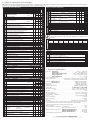
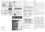
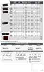
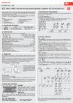
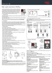
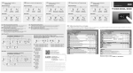
1- Warnings
GB
Installation instructions
AKO-D14112
AKO-D14123-2
AKO-D14320
AKO-D14212
AKO-14220
AKO-D14323
AKO-D14312
AKO-D14223
71mm
29mm
D142H232 Ed.03
2- Installation
-Using the equipment without following the manufacturer's
instructions may affect the device's safety requirements. To ensure
that the device operates correctly, only probes supplied by AKO
should be used.
-The unit must be installed in a location protected from vibrations,
water and corrosive gases, where the ambient temperature does
not exceed that shown in the technical data.
-To ensure a correct reading, the probe must be situated in a
location without any external heat influences except for the
temperature which is being measured or controlled.
-The power supply circuit must be provided with a main switch rated
at at least 2 A, 230 V, located close to the equipment. The cables will
enter through the back and should be type H05VV-F or H05V-K.
-The gauge will depend on local regulations, but should in no case
be less than 1 mm2.
-Connecting wires for the relay contacts should be sized 2.5 mm2.
-Between -40 ºC and +20 ºC, if the probe NTC is prolonged till
1.000 m with a mínimum of cable 0,5 mm², the maximum deviation will be of 0,25 ºC (extension cable for probe ref. AKO-15586)
NOTE: Equipment not compatible with AKO-14917 (external communication module) and AKO-14918 (programming key)
3- Wiring
The probe and its cable should NEVER be installed in the same conduit as power, control or supply cables.
AKO-D14112
Mode: COLD (P0=0)
1
2
3
4
5
6
I max.:
16 A
L N
16 A
7
8
9
AKO-D1412x-2
1
10 11
2
3
4
5
I max.:
16 A
L N
2 CV
6
7
8
9
AKO-D143xx
10 11
1
2
3
4
16 A
5
6
7
8
I max.:
16 A
L N
6A 8A
9
10 11
COOL
_
24 V ~
AUX
DI1
S2 o DI2
S1
COOL (P0=0)
RES (P0=1)
R. CRANKCASE
DI1
S2 o DI2
S1
DI1
S2 o DI2
S1
_
12 V ~
AUX.
FAN
R. CRANKCASE
AKO-D14120-2
AKO-D14123-2
AKO-D14112
Mode: HEAT (P0=1)
3
4
6
5
7
8
9
1
10 11
2
3
4
16 A
5
6
7
I max.:
16 A
L N
8A
8
9
10 11
RES.
R. CRANKCASE
AKO-D14312
AKO-D14320
AKO-D14323
_
24 V ~
AKO-D14212
AKO-D14220
AKO-D14223
4- Operation
Down key
Display
ECO relay
ON
FAN relay ON
COOL relay ON (P0=0)
COOL
AUX
AUX. Function as per parameter P6
S1: Probe 1, temperature in the chamber or cabinet.
S2/DI2: Probe 2, defrost or digital input 2 (as per P4)
DI1: Digital Input 1
_
12 V ~
120 V~ 50/60 Hz
230 V~ 50/60 Hz
Q
/m
5- Start-up
Pressing for 5 seconds activates Standby mode, pressing for 2
seconds returns the equipment to normal mode. In Standby mode,
the equipment performs no actions and only the indicator is
displayed on the screen.
The programming menu, allows you to scroll through the various
levels or, during the setting of a parameter, to change the value.
On power-up, the equipment will start up in Wizard mode
(P3 / 1 flashing), press N
or Q
to select the most
appropriate application and press SET.
4.1- Access to set point and programming
The wizard will configure the parameters of the equipment for
the chosen application (see table "Default settings by
application").
ESC
SET
Keyboard
AUX relay ON
5 sec.
SET
10 sec.
t
1: Multipurpose
4: Fresh fish
7: AC
2: Frozen
3: Fruits and vegetables
5: Soft Drinks 6: Bottle racks
8: Heat / Incubators
RES relay ON (P0=1)
Light ON (P6=3)
Release SET
to access the
set point
Change set point (SP)
Change
value
Temperature
Indication
Programming Menu (parameters)
Change
Menu
OK
Change
param.
OK
SET
Level 1
Menu
Change
value
OK
SET
Level 2
Parameters
ESC
ESC
Exit Programming
Return to
Level 1
SET
Level 3
Values
Back up one level without saving changes
ESC
35D142232 REV.02 2010
New
Value
Current
Value
Up key N
/H
Pressing for 5 seconds starts/stops defrosting.
The programming menu, allows you to scroll through the
various levels or, during the setting of a parameter, to change
the value.
Accept value
and exit
SET
SET key
Press for 5 seconds to modify the set point (SP).
Press for 10 seconds to go to the programming menu.
In the programming menu, go to the level displayed or accept
the new value while setting a parameter.
Release SET
to access
programming
www.ako.com
[email protected]
ESC key / %
Press for 5 seconds to start/stop Fast Freezing mode (rapid
cooling).
In the programming menu, exit without saving parameter,
return to previous level or exit programming.
Temperature
Indication
AKO ELECTROMECÀNICA, S.A.L.
DEF relay ON
We reserve the right to supply materials which may be slightly
different from those described in our Data Sheets. Updated
information on our web site: www.ako.com
Fast Freezing
mode
Standby
mode
120 V~ 50/60 Hz
230 V~ 50/60 Hz
AUX.
R. CRANKCASE
Program Mode
_
12 V ~
AUX
DI1
S2 o DI2
S1
_
12 V ~
DI1
S2 o DI2
S1
AKO-D142xx
Av. Roquetes, 30-38
08812 Sant Pere de Ribes
Barcelona (España)
2
COOL
Tel. (34) 938 142 700
Fax (34) 938 934 054
1
I max.:
16 A
L N
16 A
120 V~ 50/60 Hz
230 V~ 50/60 Hz
6 - Table of parameters and messages
Def. column shows factory-set default parameters. Those marked with * are variable parameters depending on the application chosen in the wizard or the P3 parameter (see table "Default parameters
by application"). If not indicated otherwise, the temperature values are in ºC. (Equivalent velues in °F)
AKO-D14312, AKO-D14320, AKO-D14323
AKO-D14212, AKO-D14220, AKO-D14223
AKO-D14112, AKO-D14123-2
Menus and description
Level 1
AKO-D14312, AKO-D14320, AKO-D14323
AKO-D14212, AKO-D14220, AKO-D14223
AKO-D14112, AKO-D14123-2
Menus and description
Level 1
rE Level 2
Control
Level 3
Description
With NTC
Temperature Adjustment (Set Point)
SP (limits depending on probe type)
(ºC/ºF)
With PTC
C0 Calibrating probe 1 (Offset)
C1 Probe 1 differential (Histeresis)
(ºC/ºF)
(ºC/ºF)
Upper blocking of the set point
With NTC
(ºC/ºF)
With PTC
C2 (cannot be set above this value)
C3 Lower blocking of the set point (cannot be set below this value)
(ºC/ºF)
-50
(-58ºF)
-20.0
0.1
C3
99
(210ºF)
150
(302ºF)
0.0 20.0
2.0 20.0
99
99
(210ºF) (210ºF)
150
(302ºF)
-50
(-58ºF) C2
C6
C7
C8
C9
C10
C11
2=OFF-ON/ON-OFF (since the last shut-down /start-up)
Protection delay time (value of the option selected in parameter C4)
(min.)
Status of COOL relay with probe fault
0=OFF; 1=ON; 2=Average based on last 24 hours prior to probe fault;
3=ON-OFF as prog. C7 and C8 (in heat mode always OFF)
Time relay ON in case of faulty probe
(min.)
(If C7=0 and C8¹
0, the relay will always be OFF deenergised)
Time relay OFF in case of fault of probe 1
(min.)
(If C8=0 and C7¹
0, the relay will always be ON energised)
Maximum duration of fast freezing mode. (0=off)
(h.)
Change set point (SP) in fast freezing mode, when it reaches this point (SP + C10)
(ºC/ºF)
returns to normal. (SP+C10 ³
C3) (0=OFF)
Length of inactivity at digital input to activate ECO mode
(h.)
(Only if P10 or P11=1 and P0=0) (0=OFF)
Change set point (SP) in ECO mode (SP+C12 £
C2) (0=off)
(ºC/ºF)
Exit to Level 1
C12
EP
DEFROST Control (if P0=0 Direct, Cold)
dEF Level 2
Level 3
Description
d0 Defrost frequency (Time between two starts)
d1 Maximum defrost duration (0=defrost deactivated)
Type of message during defrost:
d5
d6
d7
d8
FAn
Defrost on equipment start-up
0=NO, First defrost as per d0, 1=YES, First defrost as per d6
Defrost start delay on equipment start-up
Defrost type: 0=Resistors, 1=Inverted cycle, 2=Fan / air
(In two-relay equipment, P6 must be programmed to zero), 3=Compressor off
Calculated time between defrost periods:
0=Total actual time; 1 =Sum of times the compressor is on
Drip time at end of defrost (compressor and fans off) (if P4 ¹
1)
Exit to Level 1
d9
EP
Level 2
FAN control (Evaporator)
In 2-relay models P6 must be set to 0
Level 3
F0
F1
F2
F3
Description
Fan shut-down temperature as per probe 2 (if P4 ¹
1)
Probe 2 differential (If P4 ¹
1)
Stop fans when stopping compressor 0=No, 1=Yes
Fan status during defrost: 0=Off; 1=On
Starting delay after defrost (if F3=0)
F4 Will only operate if it is higher than d9
Stop fans on opening the door 0=No, 1=Yes
F5 (Requires a digital input configured as port P10 or P11=1)
EP Exit to Level 1
P8
·
·
·
·
·
·
·
·
·
·
P9
P10
P11
·
0
0
0
0
0
0
0
10
5
120
0
0
0
24
48
-50
(-58ºF) C3-SP
0
2
24
0
2
C2-SP
·
·
·
·
·
·
·
·
·
·
·
·
(ºC/ºF)
(min.)
0
2
2
5
0
255
-50
8
99,9
(-58ºF) (46ºF) (211ºF)
0
0
1
0
0
255
0
0
3
(ºC/ºF)
-50
(-58ºF)
0,1
0
0
(min.)
0
99,9
(211ºF)
2,0 20,0
1
1
1
3
99
1
3
·
·
·
1
1
2
0
0
1
·
·
·
·
0
0
6
·
·
·
0
0
6
·
·
·
0
0
0
0
1
1
·
·
·
·
·
·
·
·
·
Valores Min.
Mín. Def.
Def. Max.
Máx.
Values
0
-
99
·
·
·
·
·
·
·
·
·
·
·
·
·
·
·
DEFAULT SETTINGS BY APPLICATION (P3)
·
·
·
·
·
·
·
·
· SP
1
Multipurpose
2
Frozen
2 (35,6ºF)
4
20
8 (46ºF)
1
0
-18 (-0,4ºF)
4
20
0 (32ºF)
0
0
·
·
·
·
·
· MESSAGES
·
·
· L5 Access code (Password) request
dEF
·
·
·
E1
·
·
·
·
· E2
·
·
· AH
0
0
1
AL
(min.)
·
· AE
0
1
255 ·
·
·
·AES
Adt
PAb
Values Min. Def. Max.
(ºC/ºF)
0
WARNING: The default parameters by type of application have been defined for the
most common applications. Check that these parameters are suitable for your
installation.
d0
d1
Values Min. Def. Max.
(h.)
·
· F0
0
96 ·
(min.)
0
255 ·
·
· F3
P0
d2 0=Current temperature; 1=Temperature at start of defrost; 2=Display dEF message
(min.)
d3 Maximum duration of message (time added at the end of the defrost)
1)
d4 Defrost end temperature (probe 2) (If P4 ¹
·
·
·
Temperature display mode
0=Whole in ºC
1=One decimal in ºC
2=Whole in ºF
3=One decimal in ºF
Probe to be displayed (as per parameter P4)
0=visualization of all the probes in sequence; 1=Probe 1; 2=Probe 2; 3=Probe 3 (1)
Selection of probe type 0=NTC; 1=PTC
Configuring digital input 1 0= Off
1=Door contact
2=External alarm
3=Severe external alarm
4=Slave defrost
5=Act. modo ECO
6=Act. Fast Freezing (If C9 ¹
0)
Configuring digital input 2 0= Off
1=Door contact
2=External alarm
3=Severe external alarm
4=Slave defrost
5=Act. modo ECO
6=Act. Fast Freezing (If C9 ¹
0)
Digital input polarity 1 0=Energised on closed contact, 1=Energised on open contact
Digital input polarity 2 0=Energised on closed contact, 1=Energised on open contact
Exit to Level 1
P12
P13
EP
·
·
·tid Nivel
2
Control
Acceso e Información
and information
control
Level 22 Access
Description
Nivel 33
Descripción
Level
120 ·
·
· L5 Access code (Password)
PU Program version (Information)
·
·
· Pr Program revision (Information)
3
EP Exit to Level 1
120 ·
·
·EP Exit Programming
-50
(-58ºF)
Type of delay for protection of the compressor:
C4 0=OFF/ON (since the last disconnection); 1=ON (since start-up/reset);
C5
P7
Values Min. Def. Max.
3
Fruits and
vegetables
10 (50ºF)
4
20
30 (86ºF)
1
0
4
Fresh
fish
0 (32ºF)
4
20
8 (46ºF)
1
0
5
Soft Drinks
6
Bottle Racks
7
AC
3 (37,4ºF)
24
20
8 (46ºF)
1
0
12 (53,6ºF)
24
20
30 (86ºF)
1
0
21 (69,8ºF)
96
0
99 (210ºF)
1
0
8
Heat/
Incubators
37 (98,6ºF)
1
Indicates a defrost is underway. (Only if parameter d2=2)
D
D
Probe 1 faulty (open circuit, crossover, NTC: temp. >99°C or <-50 °C
PTC: temp. >150 °C or <50 °C) - (equivalent limits in °F)
D A
Probe 1 faulty (open circuit, crossover, NTC: temp. >99°C or <-50 °C
PTC: temp. >150 °C or <50 °C) - (equivalent limits in °F)
D A
Flashing: maximum temperature alarm on probe 1 (A1)
Flashing: minimum temperature alarm on probe 1 (A2)
External alarm activated (only if parameter P10 or P11=2)
Severe external alarm activated (only if parameter P10 or P11=3)
Defrost time-out alarm (only if parameter A8=1)
Door open alarm (Only if P10 or P11=1 and as per time at A12)
D
D
D
D
D
D
A
A
A
A
D: Displays the message on the display, A: Activates the alarm relay (if available).
·
·
·
·
7- Technical specifications
·
·
·
·
_ ±20% 2.5 VA
Power supply AKO-D14112. . . . . . . . . . . . . . . . . . . . . . . . . . . . . . . . . . 12/24 V ~
AKO-D14123-2 . . . . . . . . . . . . . . . . . . . . . . . . . . . . 230 V~ ±10% 50/60 Hz 3.5 VA
·
·
AKO-D14220/D14320/D14120-2 . . . . . . . . . . . 120 V~ +8% -12% 50/60 Hz 4 VA
AKO-D14223/D14323. . . . . . . . . . . . . . . . . . . . . . 230 V~ ±10% 50/60 Hz 3.75 VA
_ ±20% 2 VA
AKO-D14212/D14312 . . . . . . . . . . . . . . . . . . . . . . . . . . . . . . . 12 V ~
Maximum Voltage SELV circuits . . . . . . . . . . . . . . . . . . . . . . . . . . . . . . . . . . . . . . . . . . . . . . . . . 20 V
ALARMS control (visual)
AL Level 2
Level 3
Description
Values Min. Def. Max.
Inputs (According to P4) . . . . . . . . . . . . . . 2 input NTC/PTC + 1 digitised input (PTC only AKO-D141xx)
0
0
1
·
·
·. . . . . . . . . . . . . . . . . . . . . . . . . . . . . . . . . 1 input NTC/PTC + 2 digitised input (PTC only AKO-D141xx)
A0 Configuration of temperature alarms: 0=Relative to SP; 1=Absolute
99,9 99,9
·
·
With NTC
Relay COOL AKO-D14123-2 2 CV . . . . . . . . . . . . . . . . . . . . . . . . . (EN60730-1: 16(10) A 250 V~)
(211ºF) (211ºF) ·
(ºC/ºF)
A2
A1 Maximum alarm probe 1 (must be greater than SP)
Other models 16 A . . . . . . . . . . . . . . . . . . . . . . . . . . . . (EN60730-1: 12(9) A 250 V~)
150
With PTC
(302ºF) ·
Relay FAN 6 A . . . . . . . . . . . . . . . . . . . . . . . . . . . . . . . . . . . . . . . . . . . . (EN60730-1: 5(4) A 250 V~)
-50
-50
(ºC/ºF) (-58ºF) (-58ºF) A1 ·
·
·
Relay AUX 8 A . . . . . . . . . . . . . . . . . . . . . . . . . . . . . . . . . . . . . . . . . . . . (EN60730-1: 8(4) A 250 V~)
A2 Minimum alarm probe 1 (must be less than SP)
Number of relay operations . . . . . . . . . . . . . . . . . . . . . . . . . . . . . . . EN60730-1: 100.000 operations
(min.)
·
·
0
120 ·
0
A3 Temperature alarm delay during start-up
Types of probe . . . . . . . . . . . . . . . . . . . . . . . . . . . . . . . . . . . . . NTC AKO-149xx / PTC AKO-1558xx
(min.)
·
·
0
0
99 ·
A4 Temperature alarm delay after completion of a defrost
(min.)
·
·
0
30
99 ·
A5 Temperature alarm delay after reaching the value of A1 or A2
Measurement range NTC. . . . . . . . . . . . . . . . . . . . . . . . . . . . . -50,0 ºC a +99,9 ºC (-58,0 ºF a 211 ºF)
(min.)
0
120 ·
·
·
0
A6 External alarm delay when receiving digital input signal (P10 or P11=2 or 3)
PTC . . . . . . . . . . . . . . . . . . . . . . . . . . . . . -50,0 ºC a +150 ºC (-58,0 ºF a 302 ºF)
Desactivation delay of the external alarm when the signal of the digital input
Resolution . . . . . . . . . . . . . . . . . . . . . . . . . . . . . . . . . . . . . . . . . . . . . . . . . . . . . . . . . . . . . . . 0,1 ºC
(min.)
0
0
120 ·
·
·
A7 disappears (P10 or P11=2 or 3)
Working environment . . . . . . . . . . . . . . . . . . . . . . . . . . . . . . . . . . . . . -10 a 50 ºC, humidity <90 %
·
·
·
0
0
1
A8 Show warning if defrost is terminated by time-out 0=No, 1=Yes
Ambient storage humidity . . . . . . . . . . . . . . . . . . . . . . . . . . . . . . . . . . -30 a 70 ºC, humidity <90 %
Alarm relay polarity 0=Relay ON in alarm (OFF no alarm)
0
0
1
·
·
A9 1=Relay OFF on alarm (ON with no alarm)
Class of protection - front panell. . . . . . . . . . . . . . . . . . . . . . . . . . . . . . . . . . . . . . . . . . . . . . . . IP65
Fixation . . . . . . . . . . . . . . . . . . . . . . . . . . . . . . . . . . . . . . . . . . . . . . . . Panel-mounted with anchors
(ºC/ºF)
·
·
0,1
1,0 20,0 ·
A10 Temperature Alarm Differential (A1 and A2)
Panel cutout dimensions . . . . . . . . . . . . . . . . . . . . . . . . . . . . . . . . . . . . . . . . . . . . . . . . . 71 x 29 mm
(min.)
·
·
0
2
120 ·
A12 Door open alarm delay (if P10 or P11=1)
·
·
·
Front panel dimensions . . . . . . . . . . . . . . . . . . . . . . . . . . . . . . . . . . . . . . . . . . . . . . . . . . 79 x 38 mm
EP Exit to Level 1
General status
CnF Level 2
Depth . . . . . . . . . . . . . . . . . . . . . . . . . . . . . . . . . . . . . . . . . . . . . . . . . . . . . . . . . . . . . . . . . . 61 mm
Level 3
Description
Values Min. Def. Max.
Connections . . . . . . . . . . . . . . . . . . . . . . . . . . . . . . . . . . . . Screw terminals for cables up to 2.5 mm²
0
1
· Rating of control device: built-in, automatic operation feature Type 1.B, for use in clean environments,
P0 Type of operation 0=Direct, Cold;1=Inverted, Heat
(min.)
0
0
255 ·
·
·
P1 Delay of all functions on receiving electrical power
Class A software and continuous operation. Pollution classification 2 s/ UNE-EN 60730-1.
Access code (password) functions
·
·
·
Double insulation between supply, secondary circuit and relay output.
0
0
2
P2 0=Inactive; 1=Block access to parameters; 2=Keyboard lock
Rated pulse voltage . . . . . . . . . . . . . . . . . . . . . . . . . . . . . . . . . . . . . . . . . . . . . . . . . . . . . . . . 2500 V
Set the default parameters according to the type of application (see accompanying table)
Temperature during ball-pressure test Accessible parts. . . . . . . . . . . . . . . . . . . . . . . . . . . . . . 75 ºC
1=Multipurpose
2=Frozen
3=Fruit and Vegetables
1
8
·
·
·
P3 4=Fresh Fish
Parts which position active elements . . . . . . . . . . . . . . 125 ºC
5=Soft Drinks
6=Bottle Racks
7=AC
8=Heat/Incubators
Voltage and current as per EMC tests
AKO-D14123-2/D14223/D14323 . . . . . . . . . . 207 V, 17 mA
Selection of type of input
AKO-D14220/D14320/D14120-2 . . . . . . . . . . 105 V, 36 mA
·
·
·
1
1
2
P4 1=1 probe + 2 digital inputs, 2=2 probes +1 digital input
AKO-D14112/D14212/D14312 . . . . . . . . . . . 9,6 V, 181 mA
0
1
255 ·
·
·
P5 Address (only systems with built-in communications)
Current of radio jamming supression tests . . . . . . . . . . . . . . . . . . . . . . . . . . . . . . . . . . . . . . . . . 270 mA
Configuration of AUX relay
2=Alarm
P6 1=defrost
0=Fan (only 2-relay equipment)
3=Light
0
0
1
·
·
·
·
0
1
3
·
·
User Manual available at www.ako.com