1
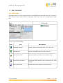
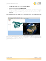
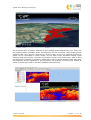
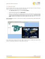
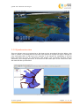
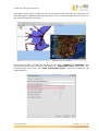
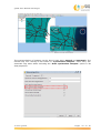
GVSIG USER MANUAL
3D PLUGIN
gvSIG User Manual: 3D Plugin
San Vicente Martir Street, 84 – 5ºA,
46002 Valencia, Spain
Information: [email protected]
www.gvsig.com
Telephone: (+34) 963516309
FAX: (+34) 901 021 995
Mailing list:
There are several mailing lists in order to facilitate communication among all
stakeholders in the gvSIG project, both users and developers.
http://www.gvsig.com/en/community/mailing-lists
All software names, operating systems, hardware etc., appearing in this course are
trademarks of their respective companies or organizations.
This document is distributed under license Creative Commons ReconocimientoCompartirIgual 3.0 Unported (http://creativecommons.org/licenses/bysa/3.0/deed.es)
© 2015 gvSIG
Pages
2
of 19
gvSIG User Manual: 3D Plugin
Contents
1 3D PLUGIN.......................................................................... 4
1.1 3D tools.................................................................................................. 4
1.1.1 3D View..................................................................................................... 5
1.1.2 Spherical 3D view...................................................................................... 5
1.1.2 Flat 3D view............................................................................................... 8
1.1.3 Synchronize view....................................................................................... 9
1.1.4 Synchronize viewport................................................................................. 11
1.1.5 Full screen mode....................................................................................... 13
1.2 3D Properties......................................................................................... 14
1.2.1 General 3D preferences............................................................................. 14
1.2.2 3D View properties..................................................................................... 14
1.2.3 3D Layer properties................................................................................... 15
© 2015 gvSIG
Pages
3
of 19
gvSIG User Manual: 3D Plugin
1 3D PLUGIN
1.1 3D tools
3D plugin offers to users several tools to create 3D views from 2D views. In “3D View”
there are the main tools related to 3D plugin. They also have the corresponding button
bar.
Menu
Button bar
Let see every tool available:
Icon
Tool
Description
Spherical 3D view
Create a Spherical 3D view from active 2D view.
Flat 3D view
Create a Flat 3D view from active 2D view.
Synchronize view
Synchronize 3D view with associated 2D view.
Synchronize viewport
Synchronize 3D viewport with associated 2D view
viewport.
Full screen mode
Indicate full screen mode to active 3D view.
© 2015 gvSIG
Pages
4
of 19
gvSIG User Manual: 3D Plugin
1.1.1 3D View
The default 3D view is displayed like this:
3D view is composed by five components:
1. Minimap: it shows what area of the Earth is being shown and the center point of
3D view.
2. View controller: It is composed by nine buttons. The first button allows user to
move the viewport, the first pair of buttons allows user to increase or decrease
zoom, the second pair of buttons allows user to rotate viewport, the third pair of
buttons allow user to increase the grade inclination and the fourth pair of buttons
allows user to increase or decrease vertical exaggeration.
3. Status bar: it shows the altitude of viewport, coordinates of mouse
4. Scale: it shows scale of current viewport.
5. North indicator: it indicates the direction of north and viewport inclination grade.
1.1.2 Spherical 3D view
This tool allows users to create a Spherical 3D view from active 2D view. To create a
Spherical 3D view it is necessary to meet the following requirements:
© 2015 gvSIG
Pages
5
of 19
gvSIG User Manual: 3D Plugin
•
One 2D view active with at least one layer added.
•
Active view projection must be EPSG:4326.
•
There is not a Spherical 3D view created with the active view. There can only be
one 3D view with the same type at the same time. Due to this, there can only be
two 3D views (spherical and flat) associated with the same 2D view at the
same time.
If all requirements are met, just do click on menu or bar button and a new Spherical 3D
view will be created.
When a new 3D view is created, it takes the loaded layers in 2D to transform it into 3D
layers to show it at Spherical 3D view. It is important to know that only EPSG:4326
projected layers will be loaded at 3D view.
© 2015 gvSIG
Pages
6
of 19
gvSIG User Manual: 3D Plugin
The transformation of layers depends on the loading mode indicated by user. There are
two loading modes available: raster and elevation. On the one hand, raster loading mode
indicates that layer will be converted to raster image. All kind of supported layers by
gvSIG can be converted to raster image. On the other hand, elevation loading mode
indicates that layer will be converted to elevation model. Only raster layers with at least
one band can be loaded as elevation. Afterwards, how to indicate loading mode with other
3D properties will be explained in this document. An example of raster layer loaded as
raster (colored layer) and as elevation (DEM) at the same time:
© 2015 gvSIG
Pages
7
of 19
gvSIG User Manual: 3D Plugin
1.1.2 Flat 3D view
This tool allows users to create a Flat 3D view from active 2D view. To create a Flat 3D
view it is necessary to meet the following requirements:
•
One 2D view active with at least one layer added.
•
Active view projection must be EPSG:4326.
•
There is not a Flat 3D view created with the active view. There can only be one 3D
view with the same type at the same time. Due to this, there can only be two 3D
views (spherical and flat) associated with the same 2D view at the same
time.
If all requirements are met, just do click on menu or bar button and a new Flat 3D view
will be created.
In the same way as Spherical 3D view, when a Flat 3D view is created, the layers of 2D
view are converted to 3D layers to show them at 3D view.
© 2015 gvSIG
Pages
8
of 19
gvSIG User Manual: 3D Plugin
1.1.3 Synchronize view
This tool allows users to synchronize a 3D view and an associated 2D view. When a 3D
view is created, it is linked with the 2D view. This permits to register 2D layers changes to
copy and apply them to 3D layers. For example, if we change the symbology of one 2D
layer and then we click on Synchronize view button, the converted 3D layer will be
affected by this change. Moreover, If we have two 3D views open at the same time, both
3D views will be synchronized.
© 2015 gvSIG
Pages
9
of 19
gvSIG User Manual: 3D Plugin
The upper image shows a Spherical 3D view desynchronized because the symbology of
2D view layers is different from 3D view layers. If we execute Synchronize view tool, we
will see both views synchronized.
The synchronization of views can be done in two ways: manual and automatic. The
manual way is run when clicking on bar button or “Synchronize view” menu entry. The
automatic way starts when the “Auto synchronize layers” option is activated in 3D
View properties.
© 2015 gvSIG
Pages
10
of 19
gvSIG User Manual: 3D Plugin
When automatic synchronization is activated, all 2D layer changes will be copied to 3D
layers. The 2D view changes copied are:
•
Add new layer.
•
Remove layer.
•
Move layer.
•
Layer visibility.
•
Layer symbology.
1.1.4 Synchronize viewport
This tool allows users to synchronize the viewport of 3D view and the viewport of
associated 2D view. When a 3D view is created, it is linked with the 2D view. This permits
to get the viewport of 2D view and indicates it to 3D view. Moreover, If we have two 3D
views open at the same time, both 3D views will be synchronized.
The upper image shows a Spherical 3D view desynchronized because the viewport of 2D
view is different from 3D view. If we execute Synchronize viewport tool, we will see both
views synchronized.
© 2015 gvSIG
Pages
11
of 19
gvSIG User Manual: 3D Plugin
The synchronization of viewport can be done in two ways: manual and automatic. The
manual way runs clicking on bar button or “Synchronize viewport” menu entry. The
automatic way starts when activating the “Auto synchronize viewport” option in 3D
View properties.
© 2015 gvSIG
Pages
12
of 19
gvSIG User Manual: 3D Plugin
When automatic viewport synchronization is activated, all 2D viewport changes will be
copied to 3D viewport.
1.1.5 Full screen mode
This tool allows users to indicate full screen mode to activate 3D view. To indicate full
mode it is necessary to have one 3D view active. If one 3D view is activated, just do
click on menu or bar button and full screen 3D view will be created.
To close full screen window press ESC key.
1.2 3D Properties
1.2.1 General 3D preferences
3D Plugin has the next general preferences:
© 2015 gvSIG
Pages
13
of 19
gvSIG User Manual: 3D Plugin
General 3D preferences are divided into three parts:
1. Size: default dimensions of new 3D views.
2. Components: a list of options to change the visibility of 3D view components and
to enable or disable animation of viewport synchronization.
3. Cache: path of current cache and a button to remove tile cache.
The general 3D preferences changes only affect new 3D views, so if we want to apply the
changes, we have to close 3D views and create them again.
1.2.2 3D View properties
3D Plugin has the next view properties:
© 2015 gvSIG
Pages
14
of 19
gvSIG User Manual: 3D Plugin
Each 2D view has its own 3D view properties. 3D View properties are divided into three
groups:
1. Vertical exaggeration: vertical exaggerations of 3D views. It is possible to change
the vertical exaggeration from 3D view properties or from the pair of buttons at 3D
view.
2. Auto synchronized: two options to enable or disable the auto synchronization of
layer or viewport.
3. Visibility of default layers: three options to change the visibility of default loaded
layers at 3D views.
1.2.3 3D Layer properties
3D Plugin provides 3D layer properties to indicate several options. Depending on the type
of layer and loading mode selected, some properties will be enabled or disabled.
3D Vector layer properties
Vector layers have two loading modes: Rasterized vector mode and Elevation mode.
Rasterized vector mode converts vector layer to raster layer in order to show it at 3D view
as raster. Elevation mode converts vector layer to DEM (Digital Elevation Model) taking
elevation values from indicated field (not available yet).
If Rasterized vector mode is selected, vector layer will have the following properties:
© 2015 gvSIG
Pages
15
of 19
gvSIG User Manual: 3D Plugin
3D Vector layer properties are divided into five groups:
1. Loading mode: it indicates that vector layer has to be loaded as a raster layer at
3D view.
2. Level of details: minimum and maximum detail level of layer. Minimum level of
detail indicates at what level the layer will be visible. For example if we indicate
two to minimum level, layer will be invisible at zero and one detail level. Maximum
level of detail indicates the maximum level of detail calculated. For example, if we
indicate ten to maximum level of detail, plugin only will calculate ten levels of
details. If we indicate zero as maximum and minimum level, 3D Plugin will
calculate the best number of detail levels in relation to resolution layer.
3. Zero level resolution: it indicates the relationship between resolution and zero
level of detail. If we indicate zero level resolution to high, layer will be shown with
more resolution at zero detail level. If we indicate zero level resolution to low,
layer will be shown with less resolution at zero detail level.
4. Tile size: it indicates size of tiles.
5. Elevation: elevation part only is available if elevation loading mode is selected
If Elevation mode is selected, vector layer will have the following properties:
© 2015 gvSIG
Pages
16
of 19
gvSIG User Manual: 3D Plugin
When we select elevation model, elevation group properties will be enable with other
options to indicate:
1. Elevation field: it indicates the field that has elevation values.
2. Units: it indicates the units of elevation values. Two options: meters and feet.
3. NoData: it indicates NoData value. All points that have indicated NoData value will
be transparent at 3D view.
3D Raster layer properties
Raster layers have two loading modes: Raster image and Elevation mode. Raster
image loads raster layer at 3D view. Elevation mode converts rater layer to DEM (Digital
Elevation Model) taking elevation values from first raster band.
If Raster image mode is selected, raster layer will have the following properties:
© 2015 gvSIG
Pages
17
of 19
gvSIG User Manual: 3D Plugin
3D Raster layer properties are divided into five groups:
1. Loading mode: it indicates what raster layer will be loaded at 3D view.
2. Level of details: minimum and maximum detail level of layer. Minimum level of
detail indicates what level the layer will be visible at. For example if we indicate
two to minimum level, layer will be invisible at zero and one detail level. Maximum
level of detail indicates the maximum level of detail calculated. For example, if we
indicate ten to maximum level of detail, plugin only will calculate ten levels of
details. If we indicate zero as maximum and minimum level, 3D Plugin will
calculate the best number of detail levels in relation to resolution layer.
3. Zero level resolution: it indicates the relationship between resolution and zero
level of detail. If we indicate zero level resolution to high, layer will be shown with
more resolution at zero detail level. If we indicate zero level resolution to low,
layer will be shown with less resolution at zero detail level.
4. Tile size: it indicates size of tiles.
5. Elevation: elevation part only is available if elevation loading mode is selected
If Elevation mode is selected, vector layer will have the following properties:
© 2015 gvSIG
Pages
18
of 19
gvSIG User Manual: 3D Plugin
When we select elevation model, elevation group properties will be enable with other
options to indicate:
1. Units: it indicates units of elevation values. Two options: meters and feet.
2. NoData: it indicates NoData value. All points that have indicated NoData value will
be transparent at 3D view.
© 2015 gvSIG
Pages
19
of 19