1
PMDX-107
Isolated Speed Control
User’s Manual
Document Revision:
Date:
PCB Version:
Assembly Revision:
Serial Numbers:
PMDX
9704-D Gunston Cove Rd
Lorton, VA 22079-2366 USA
PMDX-107_Manual_12.doc
24 September 2012
1.2
24 September 2012
PCB-475D
D1
27090 and above
Web:
Phone:
FAX:
http://www.pmdx.com
+1 (703) 372-2975
+1 (703) 372-2977
©2010-2012, Practical Micro Design, Inc.
All Rights Reserved
Page 1 of 18
PMDX-107 User’s Manual
Document Revision: 1.2
PCB Revision: PCB-475D
Assembly Revision: D1
Table of Contents
1.0
Overview .................................................................................................................................3
1.1
Ordering Information (part numbers)......................................................................................................... 3
1.2
Definitions ......................................................................................................................................................... 3
1.3
Important Safety Information ........................................................................................................................ 3
1.4
Warranty Summary......................................................................................................................................... 4
1.5
Features ............................................................................................................................................................. 4
1.6
Updates to this Manual................................................................................................................................... 5
2.0
Quick Start Guide ..................................................................................................................5
2.1
Example Connections to PMDX-125 .......................................................................................................... 5
2.1.1
Normal Mode .......................................................................................................................................... 5
2.1.2
Expanded Mode....................................................................................................................................... 6
2.2
Example Connections to PMDX-132 .......................................................................................................... 6
2.3
VSD Speed Control Interface ....................................................................................................................... 7
2.4
VSD Run/Direction Interface ........................................................................................................................ 9
2.5
Configuring DIP Switches............................................................................................................................... 9
2.6
VSD Speed Calibration ................................................................................................................................... 9
2.7
Configuring PC Control Signals ..................................................................................................................10
3.0
Technical Reference.............................................................................................................10
3.1
Functional Overview .....................................................................................................................................10
3.1.1
Normal Mode ........................................................................................................................................10
3.1.2
Expanded Mode.....................................................................................................................................11
3.2
PWM Input......................................................................................................................................................11
3.3
Power Supply Isolation .................................................................................................................................12
4.0
DIP Switches .........................................................................................................................12
4.1
Operational Mode Switches ........................................................................................................................13
4.2
Relay Mode Switch ........................................................................................................................................13
4.3
Charge Pump Mode Switch .........................................................................................................................13
4.4
Fast/Slow Spindle Response Switch ...........................................................................................................13
4.5
Spindle Control Voltage Switch..................................................................................................................14
5.0
LED Indicators ......................................................................................................................14
5.1
Status LED Error Codes ..............................................................................................................................14
6.0
Connectors............................................................................................................................15
6.1
Relay and Spindle Signal Connector (J1)...................................................................................................15
6.2
PMDX Interface Connector (J2) ................................................................................................................16
7.0
Mechanical Specifications ....................................................................................................16
8.0
Electrical and Environmental Specifications .....................................................................17
Appendix A – Warranty..................................................................................................................18
PMDX-107_Manual_12.doc
24 September 2012
©2010-2012, Practical Micro Design, Inc.
All Rights Reserved
Page 2 of 18
PMDX-107 User’s Manual
Document Revision: 1.2
1.0
PCB Revision: PCB-475D
Assembly Revision: D1
Overview
This document describes the configuration and operation of the PMDX-107 Isolated Speed Control. This
document pertains to the following versions of the PMDX-107:
Circuit Board Revision:
Assembly Revision:
Serial Number Range:
1.1
PCB-475D (marked on the bottom of the board)
D1 (marked on silk screen block next to the serial number)
27090 and above
Ordering Information (part numbers)
The PMDX-107 can be built with or without components that allow the board to be mounted to an
operator’s panel, as designated by the full part numbers:
Part Number
PMDX-107
Features
Normal version with one mounting bracket
1.2
Definitions
PWM
VFD
VSD
Pulse width modulation – a digital signal that represents an analog voltage as a pulse stream
Variable Frequency Drive, used with 3-phase AC motors
Variable Speed Drive, either a DC motor speed control or a VFD
1.3
Important Safety Information
The PMDX-107 is intended for integration by the purchaser into industrial control systems. It is solely
the purchaser's responsibility to assure that the system is configured in a manner consistent with
applicable safety requirements. Practical Micro Design, Inc. does not control how this board is integrated
into the purchaser's system and cannot be responsible for guaranteeing the safety of your system.
The PMDX-107 is not guaranteed to be fail-safe. The system into which the PMDX-107 is installed should
provide fail-safe protection and emergency stop capability.
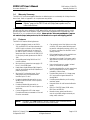
WARNING - SHOCK HAZARD:
The VSD’s analog “ground” reference is NOT necessarily at earth ground potential.
Likewise, the control signals for forward, reverse, etc. may not be referenced to ground.
Any of these may be at “mains” potential, which may be several hundred volts above
ground. These potentially dangerous voltages appear on PMDX-107 connector J1 and on
portions of the PMDX-107 circuit board. All wiring from the PMDX-107 to the VSD
should be treated as HOT and suitably protected
Care must be taken that user cannot come in contact with these voltages. An enclosure
that allows for adequate ventilation, but prevents intrusion by operator’s hands and
foreign objects, especially conductive byproducts of machining operations, should be
utilized with this board. Interlock switches on power circuits should remove power when
the enclosure is opened. Always disconnect mains power from BOTH the CNC
control system and the VSD before working on the wiring connected to either.
Automated machine tools, into which the PMDX-107 may be integrated, can cause injury. Precautions
should be taken to assure that operators are trained in their proper operation and safety procedures, and
that they are protected from moving parts that may be under remote control and may move
unexpectedly.
This product may not be used in life support or other critical safety applications.
PMDX-107_Manual_12.doc
24 September 2012
©2010-2012, Practical Micro Design, Inc.
All Rights Reserved
Page 3 of 18
PMDX-107 User’s Manual
PCB Revision: PCB-475D
Assembly Revision: D1
Document Revision: 1.2
1.4
Warranty Summary
The PMDX-107 is warranted against failure due to defective parts or workmanship for 90 days from the
date of sale. Refer to Appendix A for complete warranty details.
NOTE:
If you have an item requiring service, please see the “Warranty and
Repairs” page on the PMDX web site (http://www.pmdx.com) for
return instructions.
In general, the purchaser must pay shipping to send the unit to PMDX. For repairs covered under
warranty and with return shipping to a USA address PMDX will ship the repaired unit back to you via
ground transportation at our expense. Repairs are normally completed within 10 business days. See
Appendix A for our complete warranty details. Please see the “Warranty and Repairs” page on
our web site (http://www.pmdx.com) for full details of our repair and shipping policies.
1.5
Features
The PMDX-107 has the following features:
•
Used as a daughter board on the PMDX132, the PMDX-125, and future boards with
a PMDX option connector (Not intended
for use with boards that do not have a 10
pin PMDX option connector. If you need a
speed controller for use with the PMDX-122
or third party boards, please see the PMDX106.)
•
Can remotely control the high current relay
on PMDX-125 where mains switching must
be used for safe spindle run/stop control, e.g.
DC motor controllers like the KBIC series
used by Sherline.
•
Fully isolated interface can be used with nonisolating VFD's and motor drivers
•
Operates from a single 5 volt power supply
and receives its power from option jack on
PMDX boards
•
Sets spindle speed using PWM from CNC
control software
•
Works with any system that can supply a 25
Hz to 1 KHz PWM signal.
•
•
Needs fewer signals because PWM signal is
used for both speed, and On/Off (absence of
pulses stops motor)
Has on board inverter to supply isolated
power to interfaces as needed
•
•
Works with 5 volt analog inputs, 10 volt
analog inputs, and most potentiometer
interfaces up to 15 volts
Provides switchable filter to limit speed ramp
rate for sensitive motor drivers, reduces
probability of blown fuses
•
•
Provides isolated solid state switch to turn
spindle on and off via VFD control inputs or
a small relay
Provides safety interlock for "charge pump
OK" input monitoring and detection of
missing PWM
•
Provides speed calibration pot for setting
maximum speed
•
Provides isolated solid state switch to
control direction via VFD control inputs or a
small relay
•
Has push button for self test and calibration
modes
•
LED’s for POWER, Status, PWM active,
FWD/Run, and REV/Dir.
•
Manual run/stop, speed, and direction
control are possible using an external pot,
relays, and/or switches
•
Can be configured for VFDs that accept
Forward and Reverse commands or Run and
Direction commands
NOTE:
The PMDX-107 is not suitable for use with “universal” motor controllers such as
consumer-grade wood routers whose motors have brushes.
PMDX-107_Manual_12.doc
24 September 2012
©2010-2012, Practical Micro Design, Inc.
All Rights Reserved
Page 4 of 18
PMDX-107 User’s Manual
Document Revision: 1.2
1.6
PCB Revision: PCB-475D
Assembly Revision: D1
Updates to this Manual
Check the PMDX web site (http://www.pmdx.com) for revisions or updates to this manual and related
application notes. The latest revision of this manual is available on the PMDX-107 page (follow the links
from the main page).
2.0
Quick Start Guide
The following sections show the steps necessary to install, configure and use the PMDX-107. In general,
the steps are:
1) Power off your VSD and PMDX-125 or PMDX-132 boards, and unplug the parallel port cable from
the PMDX-125 or PMDX-132.
2) Connect the PMDX-107 to the VSD’s “speed control” interface (see section 2.3)
WARNING – SHOCK HAZARD:
Please see the warning in section 2.3 regarding potentially hazardous voltages.
3) Connect the PMDX-107 to the VSD’s Run/Direction or Forward/Reverse controls (see section 2.4)
4) Set the PMDX-107 DIP switches (see section 4.0)
5) Plug the PMDX-107 into the PMDX-125 (see section 2.1) or PMDX-132 (see section 2.2)
6) Connect the parallel port cable to the PMDX-125 or PMDX-132 board, and apply power to the VSD
and PMDX boards.
7) Calibrate the PMDX-107 speed control output voltage (see section 2.6)
8) Configure the PC or other controller to generate the proper spindle control signals (see section 2.7)
2.1
Example Connections to PMDX-125
The PMDX-107 can plug directly into a PMDX-125 Multi-Mode Breakout Board via the Option Card
Connector (J18). All power supply and control signals are brought in to the PMDX-107 via this
connector. No external power supply is required.
When connected to a PMDX-125, the PMDX-107 can operate in one of two modes as described in the
following sections.
2.1.1 Normal Mode
In “Normal” mode, the PMDX-107 receives the spindle speed controls via the following parallel port pins:
•
•
•
PC parallel port pin 14 is the Spindle Direction signal, passed through the PMDX-125
PC parallel port pin 16 is the PWM signal, passed through the PMDX-125
PC parallel port pin 17 is the Charge Pump signal into the PMDX-125, which then passes a “Charge
Pump OK” signal to the PMDX-107
PMDX-125 DIP Switch settings:
Configure the PMDX-125 for “Run in Normal Mode” or “Run in
Normal Mode with Charge Pump”. See the PMDX-125 User’s Manual
for more information.
PMDX-107 DIP Switch settings:
Configure the PMDX-107 for “Normal” mode with charge pump
enabled. Set the relay mode DIP switch and 5V/10V DIP switch as
appropriate for your VSD. See section 4.0 for information on DIP
switch settings.
PMDX-107_Manual_12.doc
24 September 2012
©2010-2012, Practical Micro Design, Inc.
All Rights Reserved
Page 5 of 18
PMDX-107 User’s Manual
Document Revision: 1.2
PCB Revision: PCB-475D
Assembly Revision: D1
2.1.2 Expanded Mode
In “Expanded” mode, the PMDX-107 shares the serial data stream with the PMDX-125 and receives the
spindle speed controls via the following parallel port pins:
•
•
PC parallel port pin 16 provides PWM speed and direction information (shared with the PMDX-125)
PC parallel port pin 17 is the Charge Pump signal (required)
NOTE:
2.2
Use of “Expanded Mode” with Mach3 requires the PMDX-107 Mach3 plug-in, which
may be downloaded from our web site at http://www.pmdx.com (see the “Support”
page for the “downloads” page). Please refer to the plug-in documentation for
information on how to configure Mach3 to access the additional output signals. Use
of “Expanded Mode” with EMC requires an EMC HAL configuration that supports
“Expanded Output Mode”.
Example Connections to PMDX-132
The PMDX-107 is designed to plug directly in to the PMDX-132 Breakout/Motherboard’s “Expansion
Connector” (J23). All power supply and control signals are brought in to the PMDX-107 via this
connector. No external power supply is required.
NOTE:
The PMDX-107 must be configured for “Normal” mode when plugged into a
PMDX-132. The PMDX-107’s “Expanded” mode is not compatible with the
PMDX-132 and it will interfere with the PMDX-132’s functionality.
When connected to a PMDX-132, the following PC parallel port signals are used to control the spindle
interface:
•
•
•
PC parallel port pin 14 is the Spindle Direction signal, passed through the PMDX-132
PC parallel port pin 16 is the PWM signal, passed through the PMDX-132
OPTIONALLY - PC parallel port pin 17 is the Charge Pump signal into the PMDX-132, which then
passes a “Charge Pump OK” signal to the PMDX-107.
The PMDX-132 and PMDX-107 configurations depend on whether you are using a “charge pump” signal
with your PMDX-132. Please refer to the PMDX-125 User’s Manual for more information about the
“charge pump” feature.
If you are using a “charge pump” signal, configure the boards as follows:
PMDX-132 jumper settings::
Configure the PMDX-132’s jumper JP1 (Output Enable) for “CP-OK{“
and jumper JP2 (Pin 17 Mode) for “CP-OK”. See the PMDX-125
User’s Manual for more information.
PMDX-107 DIP Switch settings:
Configure the PMDX-107 for “Normal” mode with charge pump
enabled. Set the relay mode DIP switch and 5V/10V DIP switch as
appropriate for your VSD. See section 4.0 for information on DIP
switch settings.
If you are not using a “charge pump” signal, configure the boards as follows:
PMDX-132 jumper settings::
Configure the PMDX-132’s jumper JP1 (Output Enable) for “not
EStop“ and jumper JP2 (Pin 17 Mode) for “normal”. See the
PMDX-125 User’s Manual for more information.
PMDX-107 DIP Switch settings:
PMDX-107_Manual_12.doc
24 September 2012
Configure the PMDX-107 for “Normal” mode with “ignore charge
pump”. Set the relay mode DIP switch and 5V/10V DIP switch as
appropriate for your VSD. See section 4.0 for information on DIP
switch settings.
©2010-2012, Practical Micro Design, Inc.
All Rights Reserved
Page 6 of 18
PMDX-107 User’s Manual
Document Revision: 1.2
2.3
PCB Revision: PCB-475D
Assembly Revision: D1
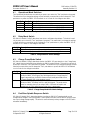
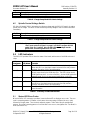
VSD Speed Control Interface
The VSD speed control interface on the PMDX-107 generates an analog voltage proportional to the
desired VSD speed. This voltage is the result of an incoming PWM signal, or when in “Expanded” mode,
from the serial command data from the PC. The PMDX-107 supports three different analog speed
control interfaces:
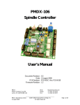
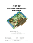
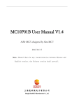
0 to +5V
The VSD expects an analog voltage between 0 and +5V, where +5V is full speed. In this
case, the PMDX-107 provides the +5V reference for its analog output circuit. See
Figure 1 for an example of the DIP switch settings and VSD connections for this
configuration.
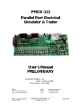
0 to +10V
The VSD expects an analog voltage between 0 and +10V, where +10V is full speed. In
this case, the PMDX-107 provides the +10V reference for its analog output circuit. See
Figure 2 for an example of the DIP switch settings and VSD connections for this
configuration.
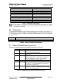
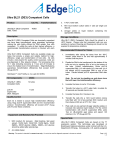
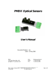
Potentiometer
(ratiometric)
The VSD expects to be connected to an external potentiometer, or requires a “max
speed” voltage that is neither +10V nor +5V. In this case, the VSD provides the analog
reference voltage to the PMDX-107’s analog output circuit. See Figure 3 for an
example of the DIP switch settings and VSD connections for this configuration. The
VSD must not apply greater than +15 volts to the PMDX-107 reference input at J1 pin 3
(referenced to J1 pin 1).
NOTE:
When using ratiometric mode, set the PMDX-107’s DIP switch for 5V mode.
See section 4.5 for more information.
WARNING – SHOCK HAZARD:
The VSD’s analog “ground” reference is NOT necessarily at earth ground potential.
Likewise, the control signals for forward, reverse, etc. may not be referenced to ground.
Any of these may be at “mains” potential, which may be several hundred volts above
ground. These potentially dangerous voltages appear on PMDX-107 connector J1 and on
portions of the PMDX-107 circuit board. All wiring from the PMDX-107 to the VSD
should be treated as HOT and suitably protected
The PMDX-107 contains isolation circuitry between the VSD interface and the lowvoltage control inputs.
DO NOT connect any terminal on connector J1 to any other connector on the
PMDX-107 or on the PMDX breakout board. Specially do not connect any terminal to
any ground (“GND”) signal. At best, doing so will defeat the isolation provided by the
PMDX-107. At worst, it will destroy the electronics in your system.
PMDX-107_Manual_12.doc
24 September 2012
©2010-2012, Practical Micro Design, Inc.
All Rights Reserved
Page 7 of 18
PMDX-107 User’s Manual
PCB Revision: PCB-475D
Assembly Revision: D1
Document Revision: 1.2
O 1 2 3
N
Config1
TBD
Config2
TBD
TBD
Config3
Config4
TBD
4 5 6
TBD
Rev/Dir
VSD
Fwd/Run
COM
Aref
Slow
Aout
5v/10v
Agnd
Analog In
0 - 5VDC
COM
PMDX-107
Figure 1 – Example 0V to 5V VSD Connections & DIP Switch Settings
O 1 2 3
N
Config1
TBD
Config2
TBD
TBD
Config3
Config4
TBD
4 5 6
TBD
Rev/Dir
VSD
Fwd/Run
COM
Aref
Slow
5v/10v
Aout
Analog In
0 - 10VDC
Agnd
COM
PMDX-107
Figure 2 – Example 0V to 10V VSD Connections & DIP Switch Settings
O 1 2 3
N
VSD
Config1
TBD
TBD
Config2
Config3
Fwd/Run
TBD
TBD
Config4
Slow
Aref
Reference
Aout
Wiper
COM
4 5 6
TBD
Rev/Dir
COM
5v/10v
Agnd
PMDX-107
Figure 3 – Example Ratiometric VSD Connections & DIP Switch Settings
PMDX-107_Manual_12.doc
24 September 2012
©2010-2012, Practical Micro Design, Inc.
All Rights Reserved
Page 8 of 18
PMDX-107 User’s Manual
PCB Revision: PCB-475D
Assembly Revision: D1
Document Revision: 1.2
2.4
VSD Run/Direction Interface
The PMDX-107 provides two sets of solid-state relay contacts to control the running and direction of the
VSD. There is a single “common” terminal, and two “normally open” terminals.
WARNING – SHOCK HAZARD:
The VSD’s analog “ground” or “common” reference is NOT necessarily at earth ground
potential. It may be at “mains” potential, or it may be several hundred volts. These
potentially dangerous voltages appear on PMDX-107 connector J1 and on portions of the
PMDX-107 circuit board.
The PMDX-107 contains isolation circuitry between the VSD interface and the lowvoltage control inputs.
DO NOT connect any terminal on connector J1 to any other connector on the
PMDX-107. Specially do not connect to any terminal on J1 to any ground (“GND”) signal.
At best, doing so will defeat the isolation provided by the PMDX-107. At worst, it will
destroy the electronics in your system.
Connector
Pin
J1 pin 4
J1 pin 5
J1. pin 6
Contacts
n/a
open
closed
(to J1 pin 4)
open
closed
(to J1 pin 4)
DIP Switch #3 “off”
(Fwd/Rev mode)
Common terminal for J1 pins 5 &6
VSD halted
VSD running forward
VSD halted
VSD running reverse
DIP Switch #3 “on”
(Run/Dir mode)
Common terminal for J1 pins 5 &6
VSD halted
VSD running
(direction determined by J8)
VSD direction = forward
VSD direction = reverse
Table 1 – Functionality of PMDX-107 VSD Run/Direction Signals
See section 6.0 for a more detailed description of the signals on each of these connectors. Also, see
section 4.0 for a more information on setting the DIP switches.
2.5
Configuring DIP Switches
Set the DIP switches according to section 4.0.
2.6
VSD Speed Calibration
The PMDX-107 contains built-in functionality to calibrate its analog speed control voltage that is output
to the VSD. The PMDX-107 has a trim pot that is used to set the maximum VSD speed. Trim pot R3
(labeled “CAL”) sets the maximum spindle speed. Use the following steps to calibrate the output voltage:
1) Connect the PMDX-107 as described in the previous sections.
2) Set the trim pot to its full counter-clockwise positions
3) Make sure that everything is clear of the spindle!!!
4) Apply power to the PMDX-107 and the VSD
5) Press & hold the push button on the PMDX-107 for at least 1 second and then release the button.
The PMDX-107 will enter “Test” mode and output its maximum PWM voltage and will command the
VSD to run the spindle in the forward direction (the STATUS led will blink to show that the
PMDX-107 is in test mode, see section 5.1).
PMDX-107_Manual_12.doc
24 September 2012
©2010-2012, Practical Micro Design, Inc.
All Rights Reserved
Page 9 of 18
PMDX-107 User’s Manual
Document Revision: 1.2
PCB Revision: PCB-475D
Assembly Revision: D1
6) Adjust the “CAL” trim pot (R3) until the spindle motor just reaches its maximum speed. Do not
increase the setting of R3 above the point at which the motor reaches maximum speed as this will
distort the speed control curve.
NOTE: The PMDX-107 will exit “Test” mode on its own after 30 seconds, at which point you will
have to restart “Test” mode if you have not completed the calibration.
7) Press & release the push button on the PMDX-107 again. The PMDX-107 will set the speed control
output to 30% of full speed with the VSD commanded in the forward direction. The 30% speed is
intended to be above the low speed cutoff threshold imposed by some VSD units. If your VSD does
not run at this test speed, please contact us for further advice.
8) Observe that your VSD is running at 30% full speed. There is no adjustment for this speed.
9) Press & release the push button on the PMDX-107 one more time to exit the “Test” mode and
return to normal operation.
10) The speed control provided by the PMDX-107 is open loop. There is no compensation by the
PMDX-107 for motor loading or other factors because there is no speed feedback on which to base
a compensation. Normal expectations should be for control within +/- 5% of target speed under no
load conditions. Speeds below 30% of full speed will likely suffer greatly under load. Speeds below
10% of full speed may track speed commands poorly.
2.7
Configuring PC Control Signals
If you are using a PC to generate the spindle control signals and interfacing to the PMDX-107 through
either a PMDX-125 (in “Run Normal” mode) or PMDX-132, then configure your software to output the
following signals on the given parallel port pins:
Signal
Direction
PWM
Charge
Pump
PC Parallel
Port Pin**
14
16
17
Description
Spindle direction. 0 = Forward 1 = Reverse
PWM (pulse width modulation). See section 3.2 for details of this signal.
Charge Pump signal. This signal should be a rough approximation of a
square wave. The PMDX-125 and PMDX-132 can be configured to use
this signal to enable their outputs and in turn send a logic “high” to the
PMDX-107 “CPOK” input. If your software does not support the charge
pump function then you must set the PMDX-107’s “Ignore CPOK” DIP
Switch to “on” (see section 4.0)
Table 2 – PC Parallel Port Signals for PMDX-107
** the parallel port pin numbers are based on the standard PC 25-pin “D” parallel port connector.
If you are using something other than a PC to generate the spindle control signals, or are using a breakout
board other than a PMDX breakout board, then configure your controller and breakout board according
to their directions.
3.0
Technical Reference
3.1
Functional Overview
This section will be filled in later.
3.1.1 Normal Mode
In “Normal” mode, the PMDX-107 receives the spindle speed controls via the following parallel port pins:
•
PC parallel port pin 14 is the Spindle Direction signal, passed through the PMDX breakout board
PMDX-107_Manual_12.doc
24 September 2012
©2010-2012, Practical Micro Design, Inc.
All Rights Reserved
Page 10 of 18
PMDX-107 User’s Manual
Document Revision: 1.2
•
•
PCB Revision: PCB-475D
Assembly Revision: D1
PC parallel port pin 16 is the PWM signal, passed through the PMDX breakout board
PC parallel port pin 17 is the Charge Pump signal into the PMDX breakout board, which then passes
a “Charge Pump OK” signal to the PMDX-107
“Normal” mode is compatible with the PMDX-125 (when in “Normal mode with Charge Pump” or
“Normal mode without charge pump”) and the PMDX-132. “Normal” mode should also be compatible
with future PMDX breakout boards.
3.1.2 Expanded Mode
In “Expanded” mode, the PMDX-107 receive spindle speed and direction commands via a serial data
stream that is shared with the PMDX-125 breakout board, using the following parallel port pins:
•
•
PC parallel port pin 16 provides the serial data stream that contains PWM speed and direction
information (shared with the PMDX-125)
PC parallel port pin 17 is the Charge Pump signal (required)
NOTE:
“Expanded” mode is compatible with the PMDX-125 when the PMDX-125 is
configured in “Expanded I/O” mode or “Expanded Output” mode. “Expanded” mode
is NOT compatible with the PMDX-132.
Use of “Expanded Mode” with Mach3 requires the PMDX-107 Mach3 plug-in, which
may be downloaded from our web site at http://www.pmdx.com (see the “Support”
page for the “downloads” page). Please refer to the plug-in documentation for
information on how to configure Mach3 to access the additional output signals. Use
of “Expanded Mode” with EMC requires an EMC HAL configuration that supports
“Expanded Output Mode”.
3.2
PWM Input
The PWM signal coming in to the PMDX-107 is idle at a logic “low” and active at a logic “high”. The duty
cycle is measured as:
(active duration) / (idle duration + active duration)
The PWM frequency must be between 25 Hz and 1,000 Hz to be considered valid. The PWM duty cycle
should be between 5% to 99.7%.
The PMDX-107 considers absence of a PWM signal (i.e. 0% or 100% duty cycle) to be a “stop” command.
When detecting a loss of PWM, there is a delay of approximately TBD of a second from the actual loss
of PWM signal until the PMDX-107 commands the VSD to stop.
The PMDX-107 is an “open loop” speed control interface. This type of interface has no way of knowing
about or correcting for speed deviations. Most applications will achieve 5% to 10% accuracy, but no
guarantee of accuracy can be given because of the number of factors involved.
The PMDX-107 is designed to provide speed commands over a range of 5% to 99.7% of full rated speed.
Settings below 5% may have significant error. Many VSDs will enforce a minimum speed greater than 5%
(as much as 30%) to cool and protect the motor. In this case the motor will not start until the PWM
reaches a suitable value.
The PMDX-107 uses the absence of a valid PWM signal to stop the spindle motor. A valid PWM signal
must always be pulsing on and off. A true 0% or 100% duty cycle signal does not pulse and will therefore
turn off the spindle motor. Most control software, including MACH, will provide the proper signal
formatting.
PMDX-107_Manual_12.doc
24 September 2012
©2010-2012, Practical Micro Design, Inc.
All Rights Reserved
Page 11 of 18
PMDX-107 User’s Manual
PCB Revision: PCB-475D
Assembly Revision: D1
Document Revision: 1.2
WARNING:
Mach3 Spindle Linearization Table
Based on versions of Mach3 available to us at the time this manual was updated
(Lockdown version R3.042.040) PMDX recommends not using the spindle speed
calibration function in Mach. Many systems do not stabilize fast enough and result
in faulty data in the linearization table. Instead, PMDX recommends using the
adjustment pot on the PMDX-107 for speed compensation (see section 2.6, VSD
Speed Calibration, for more information.
NOTE:
If you have ever run the auto calibration in Mach3, you will need to remove the
existing linearization table. The table isstored in a file named “Linearity.dat”
located in the “Mach3/macros/XXXX” directory, where “Mach3” is the directory
into which you installed the Mach software (usually C:\Mach3), and “XXXX” is
the name of the configuration. For example, if you installed Mach in the default
directory and are using the Mach3Mill configuration, the file would be:
C:\Mach3\macros\Mach3Mill\Linearity.dat
You can either delete this file, or rename it to something like “Linearity_Old.dat”.
3.3
Power Supply Isolation
The VSD interface is isolated from the low-voltage (PC and PMDX breakout board) interface and power
supply. Do not connect the VSD’s interface to the computer interface or power supply by any method
other than connector J1 on the PMDX-107. Doing so will defeat the isolation.
4.0
DIP Switches
The PMDX-107 contains 6 DIP switches that determine various aspects of its behavior. The DIP switches
are numbered “1” through “6”. These numbers also appear on the DIP switch. The functional labels
shown in the table below also appear on the circuit board’s silkscreen, next to the DIP switch.
O 1 2 3
N
4 5 6
Example #1
O 1 2 3
N
5v/10v
Slow
Config4
Config3
Config2
Config1
5v/10v
Slow
Config4
Config3
Config2
Config1
In the descriptions that follow, the switch positions are described as “on” or “off”. The “on” position is
with the raised portion of the switch positioned towards the silk screen labels. The “off” position is with
the raised portion of the switch positioned away from the silkscreen labels. The DIP switch also has an
arrow pointing to the “ON” position.
4 5 6
Example #2
Figure 4 - Sample DIP Switch Settings
Example #1 shows the DIP switches as shipped from the factory. All switches are “off”.
Example #2 shows the DIP switches set so that “Config 1” and “Slow” are “on” and all other switches are
“closed”.
PMDX-107_Manual_12.doc
24 September 2012
©2010-2012, Practical Micro Design, Inc.
All Rights Reserved
Page 12 of 18
PMDX-107 User’s Manual
Document Revision: 1.2
4.1
PCB Revision: PCB-475D
Assembly Revision: D1
Operational Mode Switches
The Operational Mode switches are read only on power-up or when the “Test” push-button is pressed.
This means that if you change the settings on these switches you must either press & release the “Test”
push-button or power the PMDX-107 off and back on or in order for the change to take effect.
Config 1
Off
On
Off
On
Config 2
Off
Off
On
On
Description
Normal Mode (see section 3.1.1)
Expanded Mode (see section 3.1.2)
Unused, will flash an error code on the STATUS LED
Unused, will flash an error code on the STATUS LED
Table 3 – Operational Mode DIP Switch Settings
4.2
Relay Mode Switch
DIP Switch 3, labeled “Config3” determines how the two solid-state relays behave. This switch is read
only at power-up or when the “Test” push-button is pressed. This means that if you change the settings
on these switches you must either press & release the “Test” push-button or power the PMDX-107 off
and back on or in order for the change to take effect.
Config 3
Off
On
Description
Solid-state relays operate as “Forward” and “Reverse” control signals.
Solid-state relays operate as “Run” and “Direction” control signals.
Table 4 – Relay Mode DIP Switch Settings
4.3
Charge Pump Mode Switch
DIP Switch 4, labeled “Config4” determines whether the PMDX-107 pays attention to the “Charge Pump
OK” signals that may (optionally) be provided by the PMDX breakout boards. This switch is read only at
power-up or when the “Test” push-button is pressed. This means that if you change the settings on these
switches you must either press & release the “Test” push-button or power the PMDX-107 off and back
on or in order for the change to take effect.
Config 4
Off
On
Description
Require a “Charge Pump OK” signal from the PMDX breakout boards. In this
mode the PMDX-107 will ignore any PWM signal until the “Charge Pump OK”
signal is asserted from the PMDX breakout board (usually associated with an
“Outputs Enabled” LED on the breakout board).
Ignore the “Charge Pump OK” signal from the PMDX breakout boards. In this
mode the PMDX-107 always looks for valid PWM signals. This mode can be
used, for example, when you are using a PMDX-132 board and need to use
parallel port pin 17 for some function other than a “charge pump”.
Table 5 – Charge Pump Mode DIP Switch Settings
4.4
Fast/Slow Spindle Response Switch
DIP Switch 5, labeled “Slow” determines whether how fast the PMDX-107’s analog spindle control
voltage follows changes in the incoming PWM. Some spindle controllers will not function properly when
the control voltage changes rapidly. This switch is read continuously and any changes to this DIP switch
take effect immediately.
PMDX-107_Manual_12.doc
24 September 2012
©2010-2012, Practical Micro Design, Inc.
All Rights Reserved
Page 13 of 18
PMDX-107 User’s Manual
Document Revision: 1.2
Slow
Off
On
PCB Revision: PCB-475D
Assembly Revision: D1
Description
Fast PWM filter response (approximately 1 second time constant)
Slow PWM filter response (approximately 5 second time constant)
Table 6 – Charge Pump Mode DIP Switch Settings
4.5
Spindle Control Voltage Switch
DIP Switch 6, labeled “5v/10v” determines the reference voltage and the PMDX-107 uses for its analog
spindle control voltage. This switch is read continuously and any changes to this DIP switch take effect
immediately.
5v/10v
Off
On
Description
10V reference (i.e. 10V is “full speed”)
5V reference (i.e. 5V is “full speed”)
Table 7 – Charge Pump Mode DIP Switch Settings
WARNING:
5.0
If you are connecting the VSD’s reference voltage to the PMDX-107’s
“Aref” input as shown in Figure 3 on page 8, you MUST configure this DIP
switch in the “On” position. Also, the VSD’s reference voltage must be
greater than +5V and no greater than +15 volts.
LED Indicators
The PMDX-107 provides LEDs to show the status of the board, and the state of the PWM and control
relays.
Reference
Designator
DS1
LED Name
Fwd/Run
DS2
PWM
DS3
Power
DS4
Rev/Dir
DS5
Status
Function
This LED is “on” when the “Fwd/Run” solid-state relay is energized.
When this LED is on, the relay’s contact is shorted to the relay common
terminal. See section 2.4 for more information.
This LED shows the state of the PWM signal. The brightness of the LED is
directly proportional to the PWM duty cycle. This LED is driven by the
PWM signal from the PC (or other controller). At slow PWM frequencies
(generally under 30 Hz) you may see noticeable flicker on this LED.
This LED is “on” when the PMDX-107 is powered on.
This LED is “on” when the “Rev/Dir” solid-state relay is energized. When
this LED is on, the relay’s contact is shorted to the relay common
terminal. See section 2.4 for more information.
The LED indicates the status of the PMDX-107. See Table 9 below for
more information
Table 8 – Summary of LEDs and functions
5.1
Status LED Error Codes
When the PMDX-107 encounters a problem, it uses the Status LED to display an error code. The error
code is a repeating pattern of 3 flashes, a short pause, then some number of flashes (the error code)
followed by a longer pause. Then the entire sequence repeats. Table Table 9 lists the possible flash
patterns. Note that a repeating pattern of one slow flash is not an error, but signifies that “Test Mode” is
active (see section 2.6).
PMDX-107_Manual_12.doc
24 September 2012
©2010-2012, Practical Micro Design, Inc.
All Rights Reserved
Page 14 of 18
PMDX-107 User’s Manual
PCB Revision: PCB-475D
Assembly Revision: D1
Document Revision: 1.2
Flash Pattern
Off
1 very short blip as button is pressed
Slow blink (1 per second)
3 short flashes, pause, 1 short flash, long pause
3 short flashes, pause, 2 short flashes, long pause
3 short flashes, pause, 3 short flashes, long pause
3 short flashes, pause, 4 short flashes, long pause
3 short flashes, pause, 5 short flashes, long pause
3 short flashes, pause, 6 short flashes, long pause
3 short flashes, pause, 7 short flashes, long pause
NOTE:
6.0
Description
No error, normal operation
Acknowledge that button was pressed
Test mode active (see section 2.6)
Not used on the PMDX-107
Not used on the PMDX-107
Expanded mode bit stream error
Expanded mode bit stream error
Invalid DIP Switch setting
Internal error (see note below)
Internal error (see note below)
Table 9 – Status LED Flash Patterns
If you encounter an “internal error” flash code you should power off the PMDX-107 and then
power it back on. Pressing the “Test” button is not sufficient. If you encounter the internal
error again, contact PMDX.
Connectors
The following sections describe the pin-out and functionality of each of the PMDX-107 connectors. For
all connectors, pin “1” is the pin closest to the reference designator (i.e. J1 pin 1 is the pin closest to the
“J1” text on the circuit board). In addition, all connectors have square pads on pin 1 (look on the bottom
of the circuit board).
Connector
J1
J2
Description
Speed signal to the VSD
PMDX Interface Header
Table 10 - Summary of PMDX-107 Connectors
6.1
Relay and Spindle Signal Connector (J1)
Connector J1 provides the speed control voltage from the PMDX-107 to the VSD.
Pin
1
Label
Agnd
2
Aout
3
Aref
4
5
COM
Fwd/Run
6
Rev/Dir
Description
VSD ground reference. This ground is isolated from the
PMDX-107’s power supply ground.
Spindle speed analog control voltage (output from
PMDX-107).
Optional: Spindle speed voltage reference (input to
PMDX-107 from VSD). This terminal is only used when
the VSD is designed to connect to an extern speed
control pot (see section 2.3 for examples).
Common terminal for both solid-state relays (pins 5 & 6)
Connected to the”COM” terminal for the VSD’s
“Forward” or “Run” signal (depending on the setting of
DIP switches, see section 4.2).
Connected to the”COM” terminal for the VSD’s
“Reverse” or “Direction” signal (depending on the setting
of DIP switches, see section 4.2).
Table 11 – Relay and Spindle Signal Connector Pin-Out (J1)
PMDX-107_Manual_12.doc
24 September 2012
©2010-2012, Practical Micro Design, Inc.
All Rights Reserved
Page 15 of 18
PMDX-107 User’s Manual
PCB Revision: PCB-475D
Assembly Revision: D1
Document Revision: 1.2
6.2
PMDX Interface Connector (J2)
Connector J2 provides an interface to the PMDX option connector on a PMDX breakout board. The
pin-out is proprietary.
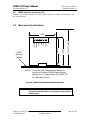
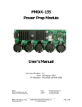
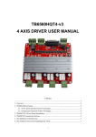
7.0
Mechanical Specifications
2.700"
Agnd
Aout
Aref
COM
Fwd/Run
2.500"
PMDX
Breakout
Board
J1
3.000" (see note)
Rev/Dir
2.550"
NOTE: This is the total required height above the
top side of the base PMDX breakout board,
allowing for 0.3" space above the PMDX-107
for cable radius into J1
Figure 5 - PMDX-107 Dimensions and Mounting Holes
WARNING:
The PMDX-107 should be protected from liquids, dirt, or chips
(especially metal chips which can cause shorts) coming in contact
with the board.
PMDX-107_Manual_12.doc
24 September 2012
©2010-2012, Practical Micro Design, Inc.
All Rights Reserved
Page 16 of 18
PMDX-107 User’s Manual
PCB Revision: PCB-475D
Assembly Revision: D1
Document Revision: 1.2
8.0
Electrical and Environmental Specifications
Power:
Power In:
+5V DC regulated +/-5%, provided by the PMDX breakout boards
125 mA maximum
Solid-State Relay Contact Ratings:
Load voltage
150 volts DC or AC maximum
Load current
80 mA maximum continuous
PWM Input Signal:
25 Hz to 1,000 Hz with 5% to 99.7% duty cycle
VSD Reference to J1:
+15 volts maximum on J1 pin 3 referenced to J1 pin 1
Environmental:
Temperature:
Relative Humidity:
PMDX-107_Manual_12.doc
24 September 2012
0° to +55° C
20% to 80% relative humidity, non-condensing
©2010-2012, Practical Micro Design, Inc.
All Rights Reserved
Page 17 of 18
PMDX-107 User’s Manual
PCB Revision: PCB-475D
Assembly Revision: D1
Document Revision: 1.2
Appendix A – Warranty
Statement
Practical Micro Design, Inc. (PMD) warrants that this hardware product is in good working
condition, according to its specifications at the time of shipment, for a period of 90 days
from the date it was shipped from PMD. Should the product, in PMD's opinion, malfunction
within the warranty period, PMD will repair or replace the product without charge. Any
replaced parts become the property of PMD. This warranty does not apply to the software
component of a product or to a product which has been damaged due to accident, misuse,
abuse, improper installation, usage not in accordance with product specifications and
instructions, natural or personal disaster or unauthorized alterations, repairs or
modifications.
Limitations
All warranties for this product, expressed or implied, are limited to 90 days from the date of
purchase and no warranties, expressed or implied, will apply after that period.
All warranties for this product, expressed or implied, shall extend only to the original
purchaser.
The liability of Practical Micro Design, Inc. in respect of any defective product will be limited
to the repair or replacement of such product. Practical Micro Design, Inc. may use new or
equivalent to new replacement parts.
Practical Micro Design, Inc. makes no other representations or warranties as to fitness for
purpose, merchantability or otherwise in respect of the product. No other representations,
warranties or conditions, shall be implied by statute or otherwise.
In no event shall Practical Micro Design, Inc. be responsible or liable for any damages arising
(a) from the use of the product;
(b) from the loss of use of the product;
(c) from the loss of revenue or profit resulting from the use of the product; or
(d) as a result of any event, circumstance, action or abuse beyond the control of Practical
Micro Design, Inc.
whether such damages be direct, indirect, consequential, special or otherwise and whether
such damages are incurred by the person to whom this warranty extends or a third party.
PMDX-107_Manual_12.doc
24 September 2012
©2010-2012, Practical Micro Design, Inc.
All Rights Reserved
Page 18 of 18