1
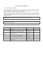
User’s Manual 32 RX64M Group Renesas Starter Kit + Tutorial Manual For e2 studio RENESAS MCU RX Family / RX600 Series All information contained in these materials, including products and product specifications, represents information on the product at the time of publication and is subject to change by Renesas Electronics Corporation without notice. Please review the latest information published by Renesas Electronics Corporation through various means, including the Renesas Electronics Corporation website (http://www.renesas.com). Rev. 1.00 Jun 2014 Notice 1. Descriptions of circuits, software and other related information in this document are provided only to illustrate the operation of semiconductor products and application examples. You are fully responsible for the incorporation of these circuits, software, and information in the design of your equipment. Renesas Electronics assumes no responsibility for any losses incurred by you or third parties arising from the use of these circuits, software, or information. 2. Renesas Electronics has used reasonable care in preparing the information included in this document, but Renesas Electronics does not warrant that such information is error free. Renesas Electronics assumes no liability whatsoever for any damages incurred by you resulting from errors in or omissions from the information included herein. 3. Renesas Electronics does not assume any liability for infringement of patents, copyrights, or other intellectual property rights of third parties by or arising from the use of Renesas Electronics products or technical information described in this document. No license, express, implied or otherwise, is granted hereby under any patents, copyrights or other intellectual property rights of Renesas Electronics or others. 4. You should not alter, modify, copy, or otherwise misappropriate any Renesas Electronics product, whether in whole or in part. Renesas Electronics assumes no responsibility for any losses incurred by you or third parties arising from such alteration, modification, copy or otherwise misappropriation of Renesas Electronics product. 5. Renesas Electronics products are classified according to the following two quality grades: “Standard” and “High Quality”. The recommended applications for each Renesas Electronics product depends on the product’s quality grade, as indicated below. “Standard”: Computers; office equipment; communications equipment; test and measurement equipment; audio and visual equipment; home electronic appliances; machine tools; personal electronic equipment; and industrial robots etc. “High Quality”: Transportation equipment (automobiles, trains, ships, etc.); traffic control systems; anti-disaster systems; anticrime systems; and safety equipment etc. Renesas Electronics products are neither intended nor authorized for use in products or systems that may pose a direct threat to human life or bodily injury (artificial life support devices or systems, surgical implantations etc.), or may cause serious property damages (nuclear reactor control systems, military equipment etc.). You must check the quality grade of each Renesas Electronics product before using it in a particular application. You may not use any Renesas Electronics product for any application for which it is not intended. Renesas Electronics shall not be in any way liable for any damages or losses incurred by you or third parties arising from the use of any Renesas Electronics product for which the product is not intended by Renesas Electronics. 6. You should use the Renesas Electronics products described in this document within the range specified by Renesas Electronics, especially with respect to the maximum rating, operating supply voltage range, movement power voltage range, heat radiation characteristics, installation and other product characteristics. Renesas Electronics shall have no liability for malfunctions or damages arising out of the use of Renesas Electronics products beyond such specified ranges. 7. Although Renesas Electronics endeavors to improve the quality and reliability of its products, semiconductor products have specific characteristics such as the occurrence of failure at a certain rate and malfunctions under certain use conditions. Further, Renesas Electronics products are not subject to radiation resistance design. Please be sure to implement safety measures to guard them against the possibility of physical injury, and injury or damage caused by fire in the event of the failure of a Renesas Electronics product, such as safety design for hardware and software including but not limited to redundancy, fire control and malfunction prevention, appropriate treatment for aging degradation or any other appropriate measures. Because the evaluation of microcomputer software alone is very difficult, please evaluate the safety of the final products or systems manufactured by you. 8. Please contact a Renesas Electronics sales office for details as to environmental matters such as the environmental compatibility of each Renesas Electronics product. Please use Renesas Electronics products in compliance with all applicable laws and regulations that regulate the inclusion or use of controlled substances, including without limitation, the EU RoHS Directive. Renesas Electronics assumes no liability for damages or losses occurring as a result of your noncompliance with applicable laws and regulations. 9. Renesas Electronics products and technology may not be used for or incorporated into any products or systems whose manufacture, use, or sale is prohibited under any applicable domestic or foreign laws or regulations. You should not use Renesas Electronics products or technology described in this document for any purpose relating to military applications or use by the military, including but not limited to the development of weapons of mass destruction. When exporting the Renesas Electronics products or technology described in this document, you should comply with the applicable export control laws and regulations and follow the procedures required by such laws and regulations. 10. It is the responsibility of the buyer or distributor of Renesas Electronics products, who distributes, disposes of, or otherwise places the product with a third party, to notify such third party in advance of the contents and conditions set forth in this document, Renesas Electronics assumes no responsibility for any losses incurred by you or third parties as a result of unauthorized use of Renesas Electronics products. 11. This document may not be reproduced or duplicated in any form, in whole or in part, without prior written consent of Renesas Electronics. 12. Please contact a Renesas Electronics sales office if you have any questions regarding the information contained in this document or Renesas Electronics products, or if you have any other inquiries. (Note 1) “Renesas Electronics” as used in this document means Renesas Electronics Corporation and also includes its majority owned subsidiaries. (Note 2) “Renesas Electronics product(s)” means any product developed or manufactured by or for Renesas Electronics (2012.4) Disclaimer By using this Renesas Starter Kit (RSK+), the user accepts the following terms: The RSK+ is not guaranteed to be error free, and the entire risk as to the results and performance of the RSK+ is assumed by the User. The RSK+ is provided by Renesas on an “as is” basis without warranty of any kind whether express or implied, including but not limited to the implied warranties of satisfactory quality, fitness for a particular purpose, title and non-infringement of intellectual property rights with regard to the RSK+. Renesas expressly disclaims all such warranties. Renesas or its affiliates shall in no event be liable for any loss of profit, loss of data, loss of contract, loss of business, damage to reputation or goodwill, any economic loss, any reprogramming or recall costs (whether the foregoing losses are direct or indirect) nor shall Renesas or its affiliates be liable for any other direct or indirect special, incidental or consequential damages arising out of or in relation to the use of this RSK+, even if Renesas or its affiliates have been advised of the possibility of such damages. Precautions The following precautions should be observed when operating any RSK+ product: This Renesas Starter Kit is only intended for use in a laboratory environment under ambient temperature and humidity conditions. A safe separation distance should be used between this and any sensitive equipment. Its use outside the laboratory, classroom, study area or similar such area invalidates conformity with the protection requirements of the Electromagnetic Compatibility Directive and could lead to prosecution. The product generates, uses, and can radiate radio frequency energy and may cause harmful interference to radio communications. However, there is no guarantee that interference will not occur in a particular installation. If this equipment causes harmful interference to radio or television reception, which can be determined by turning the equipment off or on, you are encouraged to try to correct the interference by one or more of the following measures; • ensure attached cables do not lie across the equipment • reorient the receiving antenna • increase the distance between the equipment and the receiver • connect the equipment into an outlet on a circuit different from that which the receiver is connected • power down the equipment when not in use • consult the dealer or an experienced radio/TV technician for help NOTE: It is recommended that wherever possible shielded interface cables are used. The product is potentially susceptible to certain EMC phenomena. To mitigate against them it is recommended that the following measures be undertaken; • The user is advised that mobile phones should not be used within 10m of the product when in use. • The user is advised to take ESD precautions when handling the equipment. The Renesas Starter Kit does not represent an ideal reference design for an end product and does not fulfil the regulatory standards for an end product. How to Use This Manual 1. Purpose and Target Readers 2 This manual is designed to provide the user with an understanding of how to use the e studio IDE to develop and debug software for the RSK+ platform. It is intended for users designing sample code on the RSK+ platform, using the many different incorporated peripheral devices. 2 The manual comprises of step-by-step instructions to load and debug a project in e studio, but does not intend to be a complete guide to software development on the RSK+ platform. Further details regarding operating the RX64M microcontroller may be found in the RX64M Group Hardware Manual and within the provided sample code. Particular attention should be paid to the precautionary notes when using the manual. These notes occur within the body of the text, at the end of each section, and in the Usage Notes section. The revision history summarizes the locations of revisions and additions. It does not list all revisions. Refer to the text of the manual for details. The following documents apply to the RX64M Group. Make sure to refer to the latest versions of these documents. The newest versions of the documents listed may be obtained from the Renesas Electronics Web site. Document Type Description Document Title Document No. User’s Manual Describes the technical details of the RSK+ hardware. RSK+RX64M User’s Manual R20UT2593EG Tutorial Provides a guide to setting up RSK+ environment, running sample code and debugging programs. RSK+RX64M Tutorial Manual R20UT2594EG Code Generator Tutorial Provides a guide to code generation and importing 2 into the e studio IDE. RSK+RX64M Code Generator Tutorial Manual R20UT2983EG Quick Start Guide Provides simple instructions to setup the RSK+ and run the first sample, on a single A4 sheet. RSK+RX64M Quick Start Guide R20UT2595EG Schematics Full detail circuit schematics of the RSK+. RSK+RX64M Schematics R20UT2598EG Hardware Manual Provides technical microcontroller. RX64M Group Hardware Manual R01UH0377EJ details of the RX64M 2. List of Abbreviations and Acronyms Abbreviation Full Form ADC Analog-to-Digital Converter E1 GDB On-chip Debugger GNU Debugger LCD LED Liquid Crystal Display Light Emitting Diode MCU RSK+ Micro-controller Unit Renesas Starter Kit Plus SCI UART Serial Communications Interface Universal Asynchronous Receiver/Transmitter USB Universal Serial Bus Table of Contents 1. Overview............................................................................................................................ 7 1.1 1.2 Purpose ...................................................................................................................................................... 7 Features ..................................................................................................................................................... 7 2. Introduction ........................................................................................................................ 8 2.1 Code Generator Plug in ............................................................................................................................. 8 3. Tutorial Project Workspace ................................................................................................ 9 3.1 3.2 3.3 3.4 Introduction ................................................................................................................................................ 9 2 Starting e studio and Importing Sample Code .......................................................................................... 9 Build Configurations and Debug Sessions .............................................................................................. 11 Running the Tutorial ................................................................................................................................. 13 4. Reviewing the Tutorial Program ....................................................................................... 14 4.1 4.2 Program Initialisation ............................................................................................................................... 14 Main Functions ......................................................................................................................................... 16 5. Additional Information ...................................................................................................... 20 RSK+RX64M RENESAS STARTER KIT R20UT2594EG0100 Rev. 1.00 Jun 27, 2014 1. Overview 1.1 Purpose This RSK+ is an evaluation tool for Renesas microcontrollers. This manual describes how to get the RSK+ tutorial started, and basic debugging operations. 1.2 Features This RSK+ provides an evaluation of the following features: • Renesas microcontroller programming • User code debugging • User circuitry such as switches, LEDs and a potentiometer • Sample application • Sample peripheral device initialisation code The RSK+ board contains all the circuitry required for microcontroller operation. R20UT2594EG0100 Rev. 1.00 Jun 27, 2014 Page 7 of 24 RSKRX64M 2. Introduction 2. Introduction This manual is designed to answer, in tutorial form, the most common questions asked about using a Renesas Starter Kit (RSK+). The tutorials help explain the following: • How do I compile, link, download and run a simple program on the RSK+? • How do I build an embedded application? • How do I use Renesas’ tools? Files referred to in this manual are installed using the project generator as you work through the tutorials. The tutorial examples in this manual assume that installation procedures described in the RSK+ Quick Start Guide have been completed. Please refer to the Quick Start Guide for details of preparing the configuration. These tutorials are designed to show you how to use the RSK+ and are not intended as a comprehensive introduction to 2 e studio, the compiler toolchains or the E1 emulator. Please refer to the relevant user manuals for more in-depth information. 2.1 Code Generator Plug in The Code Generator plug in for the RX64M has been used to generate the sample code discussed in this 2 document. Code Generator for e studio is a plug in tool for generating template ‘C’ source code and project settings for the RX64M. When using Code Generator, the engineer is able to configure various MCU features and operating parameters using intuitive GUI controls, thereby bypassing the need in most cases to refer to sections of the Hardware Manual. Once the engineer has configured the project, the ‘Generate Code’ function is used to generate three code modules for each specific MCU feature selected. These code modules are name ‘r_cg_xxx.h’, ‘r_cg_xxx.c’, and ‘r_cg_xxx_user.c’, where ‘xxx’ is a three letter acronym for the relevant MCU feature, for example ‘adc’. Within these code modules, the engineer is then free to add custom code to meet their specific requirement. Custom code should be added, whenever possible, in between the following comment delimiters: /* Start user code for adding. Do not edit comment generated here */ /* End user code. Do not edit comment generated here */ Code Generator will locate these comment delimiters, and preserve any custom code inside the delimiters on subsequent code generation operations. This is useful if, after adding custom code, the engineer needs to revisit Code Generator to change any MCU operating parameters. R20UT2594EG0100 Rev. 1.00 Jun 27, 2014 Page 8 of 24 RSK+RX64M 3. Tutorial Project Workspace 3. Tutorial Project Workspace 3.1 Introduction 2 e studio is an open source integrated development tool that allows the user to write, compile, program and debug a software product on many of the Renesas microcontrollers. 3.2 Starting e2 studio and Importing Sample Code • Start e studio by selecting it from the TM Windows Start Menu. The first dialog box to appear will be the Workspace Launcher. • Click ‘Browse’ and select a suitable location to store your workspace, using the ‘Create New Folder’ option as necessary. Click ‘OK’. • The e studio welcome splash screen will appear. Click the ‘Go to the workbench’ arrow button on the far right (circled in the screenshot opposite). 2 2 R20UT2594EG0100 Rev. 1.00 Jun 27, 2014 Page 9 of 24 RSK+RX64M • Once the environment has initialised, right click in the ‘Project Explorer’ window and select ‘Import…’ • The Import dialog box will now show. Expand the ‘General’ folder icon, and select ‘Existing Projects into Workspace’, then click ‘Next’. R20UT2594EG0100 Rev. 1.00 Jun 27, 2014 3. Tutorial Project Workspace Page 10 of 24 RSK+RX64M • 3. Tutorial Project Workspace The Import dialog box will allow you to specify a project to import. Click the ‘Browse’ button and locate the following directory: C:\Renesas\Workspace\RSK\RSK+RX64M • Ensure that the ‘Copy projects into workspace’ option is ticked, and then click ‘Finish’. • Click on Tutorial from the list of projects in the ‘Project Explorer’ on the left-hand side. 3.3 Build Configurations and Debug Sessions 3.3.1 Build Configuration 2 The e studio workspace will be created with two build configurations: ‘HardwareDebug’ and ‘Release’. Release This build mode has optimisation turned on, and provides little debug information. The C code execution may appear to be out of order, due to the way compiler optimises the code. This build configuration is intended for final ROM-programmable code. HardwareDebug This build mode has all optimisation turned off, and provides full debug information. This is the best configuration to use whilst developing code as C code execution will be linear. • Click the top level ‘Tutorial’ folder again, and then the arrow next to the build button (hammer icon), and select the ‘HardwareDebug’ option. • e studio will now build the code. 2 R20UT2594EG0100 Rev. 1.00 Jun 27, 2014 Page 11 of 24 RSK+RX64M 3.3.2 3. Tutorial Project Workspace Debug Configuration • Click the arrow next to the debug button (bug icon). Select ‘Debug Configurations’. • The ‘Debug Configurations’ dialog box will appear. Click the small arrow next to the ‘Renesas GDB Hardware Debugging’ option. • The debug configurations for each project will appear. Select the entry for the ‘Tutorial Hardware Debug’. • The debug configurations control page will then show for the Tutorial project. Change the main tab to ‘Debugger’ and then select ‘Connection Settings’ on the secondary tab bar that appears. • There is no need to change the debugger settings as they are preconfigured with the Tutorial project. • Refer to the RSK+RX64M User’s Manual for details of power supply configuration. 2 Note: e studio will display a warning if you attempt to connect with an incorrect power supply setting. • 2 Click the ‘Debug’ button to continue. e studio will now connect to the debugger and download the code to the target. R20UT2594EG0100 Rev. 1.00 Jun 27, 2014 Page 12 of 24 RSK+RX64M • After downloading the code a dialog box will appear asking if you would like to switch to the ‘Debug perspective’. Click ‘Remember my decision’ to prevent this dialog box from appearing in future, then click ‘Yes’ • e studio will load the new perspective, which is optimised for debugging. • To change back to the default ‘C/C++’ perspective, from the menu bar select Window > Open Perspective > Other • The ‘Open Perpsective’ dialog box will appear. Click on the desired perspective to select it then ‘OK’. • Alternatively, click on the button with the double arrow in the top right corner of the screen, as shown opposite, and select the ‘C/C++’ option that appears. 3.4 • • • • 3. Tutorial Project Workspace 2 Running the Tutorial Refer to the Description.txt file for instructions on how to configure the RSK+ and run the sample code. Once the code has been downloaded, click ‘Resume’ to run the code to the main function. The main function is set as the program entry point by default. The program counter will stop on the first instruction in the main function. Click the ‘Resume’ button in the ‘Debug’ perspective to run the rest of the code It is recommended that you run the entire tutorial demo first, before continuing to debug it. R20UT2594EG0100 Rev. 1.00 Jun 27, 2014 Page 13 of 24 RSK+RX64M 4. Reviewing the Tutorial Program 4. Reviewing the Tutorial Program 2 This section will look at each section of the tutorial code and basic debugging functionality in e studio. 4.1 Program Initialisation Before the main program can run, the microcontroller must be configured. The following parts of the tutorial program are used exclusively for initialising the RSK device so that the main function can execute correctly. The initialisation code is run every time the device is reset via the reset switch or from a power cycle. • After downloading the code, switch back to the C/C++ perspective and navigate to the Project Explorer window on the left-hand side. • Expand the ‘Tutorial’ folder by clicking on the arrow next to the folder icon, as highlighted by the red circle. • Click the arrow next to the ‘src’ folder to show the source files. • Expand the ‘cg_src’ folder in the same way and double click on ‘r_cg_hardware_setup.c’ to open the file. • Breakpoints can be set by double clicking at the left-hand edge of the source window. On the line with instruction r_system_init(), double click next to the vertical line to set a breakpoint. Note: As an alternative breakpoints may be set in the C/C++ perspective by selecting a line and using Run > Toggle Breakpoint. R20UT2594EG0100 Rev. 1.00 Jun 27, 2014 Page 14 of 24 RSK+RX64M • 4. Reviewing the Tutorial Program Click the ‘Resume’ button in the Debug perspective (or press [F8]) to run the code up to this breakpoint. Note: The program counter is indicated by the blue arrow next to the breakpoint. • Click the ‘Step Into’ button (or press [F5]), to step into the ‘R_Systeminit’ function. • The ‘R_Systeminit’ function calls several initialisation functions which configure the MCU for normal operation. This includes input/output ports, and system clocks. • The user can step through all the initialisation code by clicking the ‘Step Into’ icon and reading the code however for the purpose of this manual, it will be skipped. • Click the ‘Resume’ button, to run the code up to the main function. For further details regarding hardware configuration, please refer to the RSK+RX64M User’s Manual and the RX64MGroup Hardware Manual. R20UT2594EG0100 Rev. 1.00 Jun 27, 2014 Page 15 of 24 RSK+RX64M 4.2 4. Reviewing the Tutorial Program Main Functions This section will look at the program code called from with the main() function, and how it works. It is necessary to connect the RSK+ G1CUSB0 connection to a PC USB port and open a terminal; emulation program, such as HyperTerminal, with the settings 19200, 8, N, 1. For information on installation of the RSK+ 2 virtual COM port driver, refer to the file ‘Description.txt’ in the e studio Tutorial project. • Right click the ‘R_SCI7_Serial_Receive()’ function call and select ‘Run to Line’ to execute the program up to this line. The ‘Init_LCD()’ function call enables and configures the LCD panel, and ‘Display_LCD()’ will write “RSK+RX64M Tutorial Press Any Switch” onto the LCD. • Set a breakpoint on the ‘R_SCI7_Start()’ function call by double-clicking in the breakpoint column. • Click the ‘Step Into’ button to step into the ‘R_SCI7_Serial_Receive ()’ function. • The program counter should now move into the R_ SCI7_Serial _Receive function definition. This function is an API function provided by the Code Generator. It sets up the UART interrupt handler code to receive a specified number of bytes into a receive buffer. Once the specified number of bytes has been received, the interrupt handler code calls a callback function as shown later on in this section. • For full details on how to configure a project using Code Generator refer to the Code Generator Tutorial Manual. • Click the ‘Resume’ button resume program execution. R20UT2594EG0100 Rev. 1.00 Jun 27, 2014 to Page 16 of 24 RSK+RX64M • The program counter should come to a halt at the R_SCI7_Start function. • Step over the function by clicking the ‘Step Over’ button. Alternatively, press [F6]. 4. Reviewing the Tutorial Program The R_SCI7_Start() function enables the UART interrupts. The program then proceeds to the main while() loop. The code inside the loop waits for user input from either the UART or RSK+ switches, and then performs an A/D conversion. • Locate the function call to ‘lcd_display_adc()’ inside the while loop. • Set a breakpoint on the ‘lcd_display_adc()’ function call by double-clicking in the breakpoint column. R20UT2594EG0100 Rev. 1.00 Jun 27, 2014 Page 17 of 24 RSK+RX64M • In the Project Explorer pane, locate the file ‘r_cg_sci_user.c’ and double-click to open the source file. Scroll down to the function r_sci7_callback_receiveend(). • Set a breakpoint on the line of code inside the r_sci7_callback_receiveend function as shown opposite. • Continue to execute the program by clicking the ‘Resume’ button. R20UT2594EG0100 Rev. 1.00 Jun 27, 2014 4. Reviewing the Tutorial Program Page 18 of 24 RSK+RX64M • In the terminal; emulation window, press the ‘c’ button on the keyboard. • The program will halt at the breakpoint in the r_sci7_callback_receiveend function as shown opposite. Remove the breakpoint by double-clicking on the breakpoint column. • Continue to execute the program by clicking the ‘Resume’ button. • The program will halt at the breakpoint in the main while loop. 4. Reviewing the Tutorial Program • Remove the breakpoint by doubleclicking on the breakpoint column. Continue to execute the program by clicking the ‘Resume’ button. . The program proceeds to display the result of the A/D conversion on the LCD and in the terminal window. In addition, the running count of A/D conversions performed is displayed in binary form using LEDs 0-3 on the RSK+. Adjust the potentiometer and press SW1, SW2 or SW3 on the RSK+ and an additional A/D conversion will be performed. • Press the ‘Suspend’ button to halt program execution. • This is the extent of the tutorial code. For further details regarding hardware configuration, please refer to the RX Series Software Manual and the RX64M Group Hardware Manual. The E1 emulator features advanced logic-based event point trigger system, and full instruction on its use is outside the scope of this tutorial. For further details, please refer to the E1 Emulator User’s Manual R20UT2594EG0100 Rev. 1.00 Jun 27, 2014 Page 19 of 24 RSK+RX64M 5. Additional Information 5. Additional Information Technical Support 2 For details on how to use e studio, refer to 2 the help file by opening e studio, then selecting Help > Help Contents from the menu bar. Parts of the sample code provided with the RSK+RX64M can be reproduced using the Code Generator tool. 2 Code Generator is included as a plug in with e studio. Source files and functions generated by Code Generator are prefixed with ‘r_’ and ‘R_’, respectively. For information about the RX64M series microcontrollers refer to the RX64M Group Hardware Manual. For information about the RX assembly language, refer to the RX Series Software Manual. Technical Contact Details Please refer to the contact details listed in section 9 of the “Quick Start Guide” General information on Renesas Microcontrollers can be found on the Renesas website at: http://www.renesas.com/ Trademarks All brand or product names used in this manual are trademarks or registered trademarks of their respective companies or organisations. Copyright This document may be, wholly or partially, subject to change without notice. All rights reserved. Duplication of this document, either in whole or part is prohibited without the written permission of Renesas Electronics Europe Limited. © 2014 Renesas Electronics Europe Limited. All rights reserved. © 2014 Renesas Electronics Corporation. All rights reserved. © 2014 Renesas Solutions Corp. All rights reserved. R20UT2594EG0100 Rev. 1.00 Jun 27, 2014 Page 20 of 24 REVISION HISTORY Rev. RSKRX64M Tutorial Manual Date Description Page 1.00 Jun 27, 2014 Summary First Edition issued Renesas Starter Kit+ Manual: Tutorial Manual Publication Date: Rev. 1.00 Jun 27, 2014 Published by: Renesas Electronics Corporation http://www.renesas.com SALES OFFICES Refer to "http://www.renesas.com/" for the latest and detailed information. Renesas Electronics America Inc. 2880 Scott Boulevard Santa Clara, CA 95050-2554, U.S.A. Tel: +1-408-588-6000, Fax: +1-408-588-6130 Renesas Electronics Canada Limited 1101 Nicholson Road, Newmarket, Ontario L3Y 9C3, Canada Tel: +1-905-898-5441, Fax: +1-905-898-3220 Renesas Electronics Europe Limited Dukes Meadow, Millboard Road, Bourne End, Buckinghamshire, SL8 5FH, U.K Tel: +44-1628-651-700, Fax: +44-1628-651-804 Renesas Electronics Europe GmbH Arcadiastrasse 10, 40472 Düsseldorf, Germany Tel: +49-211-65030, Fax: +49-211-6503-1327 Renesas Electronics (China) Co., Ltd. 7th Floor, Quantum Plaza, No.27 ZhiChunLu Haidian District, Beijing 100083, P.R.China Tel: +86-10-8235-1155, Fax: +86-10-8235-7679 Renesas Electronics (Shanghai) Co., Ltd. Unit 301, Tower A, Central Towers, 555 LanGao Rd., Putuo District, Shanghai, China Tel: +86-21-2226-0888, Fax: +86-21-2226-0999 Renesas Electronics Hong Kong Limited Unit 1601-1613, 16/F., Tower 2, Grand Century Place, 193 Prince Edward Road West, Mongkok, Kowloon, Hong Kong Tel: +852-2886-9318, Fax: +852 2886-9022/9044 Renesas Electronics Taiwan Co., Ltd. 13F, No. 363, Fu Shing North Road, Taipei, Taiwan Tel: +886-2-8175-9600, Fax: +886 2-8175-9670 Renesas Electronics Singapore Pte. Ltd. 80 Bendemeer Road, Unit #06-02 Hyflux Innovation Centre Singapore 339949 Tel: +65-6213-0200, Fax: +65-6213-0300 Renesas Electronics Malaysia Sdn.Bhd. Unit 906, Block B, Menara Amcorp, Amcorp Trade Centre, No. 18, Jln Persiaran Barat, 46050 Petaling Jaya, Selangor Darul Ehsan, Malaysia Tel: +60-3-7955-9390, Fax: +60-3-7955-9510 Renesas Electronics Korea Co., Ltd. 12F., 234 Teheran-ro, Gangnam-Gu, Seoul, 135-080, Korea Tel: +82-2-558-3737, Fax: +82-2-558-5141 © 2014 Renesas Electronics Corporation. All rights reserved. Colophon 2.0 RX64M Group R20UT2594EG0100