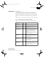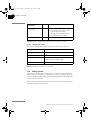
1
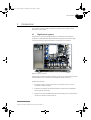
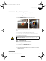
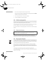
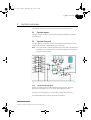
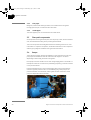
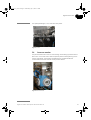
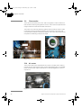
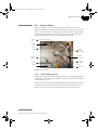
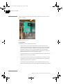
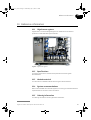
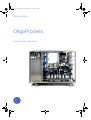
11003171_AA.book Page i Wednesday, July 6, 2005 5:14 PM
GE Healthcare
OligoProcess
Guide to Safe Operation
11003171_AA.book Page ii Wednesday, July 6, 2005 5:14 PM
11003171_AA.book Page iii Wednesday, July 6, 2005 5:14 PM
Contents
1
Introduction
1.1
1.2
1.3
1.4
1.5
2
General .............................................................................................................
Safety compliance ......................................................................................
Material compliance ..................................................................................
Safety labels and other labels ...............................................................
Intended use of OligoProcess ................................................................
General safety precautions ....................................................................
EX related safety precautions ...............................................................
Emergency procedures ............................................................................
Power failure and data backup ............................................................
Cabinet purging system ...........................................................................
Chemical resistance ..................................................................................
Recycling and disposal .............................................................................
11
11
12
12
15
15
17
19
20
22
22
22
System overview
3.1
3.2
3.3
3.4
3.5
3.6
3.7
3.8
3.9
3.10
3.11
3.12
3.13
3.14
3.15
3.16
3.17
4
5
6
8
8
9
Safety instructions
2.1
2.2
2.3
2.4
2.5
2.6
2.7
2.8
2.9
2.10
2.11
2.12
3
OligoProcess system ....................................................................................
About this Guide to Safe Operation .......................................................
The process system ......................................................................................
Control system ................................................................................................
The oligonucleotide synthesis in OligoProcess ................................
System layout ...............................................................................................
System flow path ........................................................................................
Flow path components .............................................................................
Pumps ...............................................................................................................
Valves ................................................................................................................
Conductivity monitor .................................................................................
UV monitor ......................................................................................................
Pressure monitor .........................................................................................
Flow monitor ..................................................................................................
Air sensor .........................................................................................................
Column .............................................................................................................
Pressure control valve ...............................................................................
Containers for reagents and solvents ...............................................
Junction box ..................................................................................................
Process cabinet ............................................................................................
Safety system ...............................................................................................
Electrical connections ...............................................................................
23
23
24
24
25
26
26
27
28
28
29
29
29
30
31
34
35
Installation
4.1
4.2
4.3
Environmental requirements ................................................................. 37
Site requirements ........................................................................................ 37
Unpacking ....................................................................................................... 38
OligoProcess Guide to Safe Operation 28-9578-61 Edition AA
iii
11003171_AA.book Page iv Wednesday, July 6, 2005 5:14 PM
Contents
4.4
4.5
5
Starting OligoProcess
5.1
5.2
5.3
5.4
6
Preparation of solutions ........................................................................... 43
Packing the column .................................................................................... 45
Connecting the column ............................................................................ 45
General .............................................................................................................
Creating a method ......................................................................................
Final preparation .........................................................................................
Starting a run .................................................................................................
During a run ...................................................................................................
Viewing and printing the result .............................................................
After a run and storage ............................................................................
47
47
47
48
48
48
48
Maintenance
8.1
8.2
8.3
8.4
8.5
8.6
8.7
9
41
41
41
42
Operation
7.1
7.2
7.3
7.4
7.5
7.6
7.7
8
General .............................................................................................................
Starting the process system ..................................................................
Starting UNICORN .......................................................................................
Connecting UNICORN to the process system ................................
Synthesis preparation
6.1
6.2
6.3
7
Physical installation ................................................................................... 39
Flushing and filling the system flow path ........................................ 40
General .............................................................................................................
Cleaning before maintenance/service ..............................................
Component maintenance .......................................................................
Disassembly and assembly ....................................................................
Replacement of fuses .............................................................................
Monitor calibration .....................................................................................
User maintenance schedule ..................................................................
49
50
50
50
51
51
52
Troubleshooting
9.1
9.2
9.3
9.4
9.5
9.6
General .............................................................................................................
Chemical problems .....................................................................................
UV curve problems .....................................................................................
Conductivity curve ......................................................................................
Pressure curve ..............................................................................................
Purge system ................................................................................................
53
53
53
54
54
54
10 Reference information
10.1
10.2
10.3
10.4
10.5
iv
OligoProcess system .................................................................................
Specifications ................................................................................................
Wetted materials .........................................................................................
System recommendations ......................................................................
Ordering information .................................................................................
55
55
55
55
55
OligoProcess Guide to Safe Operation 28-9578-61 Edition AA
11003171_AA.book Page 5 Wednesday, July 6, 2005 5:14 PM
1
Introduction
1
Introduction
This chapter contains a brief introduction to OligoProcess™ system and a
description of this guide.
1.1
OligoProcess system
OligoProcess is a custom designed system for reliable and cost-effective
production of DNA and RNA oligonucleotides. The system uses flow-through
column technology to keep the amidite consumption to a minimum.
Fig 1-1. OligoProcess system
OligoProcess consists of a process system, junction box, computer with monitor
and UNICORN™ control software, and a separate operator terminal.
OligoProcess features:
•
Production range from 50 to 500 mmol, 100 to 1000 mmol or more of
therapeutic oligonucleotides.
•
Explosion-proof design and industrial grade components that withstand
harsh synthesis chemicals.
•
System control by UNICORN allows for fast and easy start of the production
process and simple method scale-up.
OligoProcess Guide to Safe Operation 28-9578-61 Edition A
5
11003171_AA.book Page 6 Wednesday, July 6, 2005 5:14 PM
1
Introduction
1.2
About this Guide to Safe Operation
This guide is intended to highlight certain conditions that must be followed to
obtain and maintain safe operation of OligoProcess system. OligoProcess is an
EX-classified system wherefore this guide also contains special safety
information related to working in a potentially explosive environment.
Make sure that the information in this guide, together with the system
documentation supplied, is fully understood before the system is used.
1.2.1
Contents
The table below describes the content in each chapter in this manual.
6
Chapter
Contents
1. Introduction
Brief overview of OligoProcess and
information about this manual.
2. Safety instructions
Instructions that must be followed for
safe use of OligoProcess, labels and
emergency procedures.
3. System description
Overview of the system components,
brief description of the system flow
path and major components.
4. Installation
Basic instructions for installing the
system.
5. System start-up
Instructions for starting the system
and connecting the system to
UNICORN.
6. System preparation
Instructions for preparing the system
for a run.
7. Operation
Instructions for creating a method for a
synthesis, final checks, for starting a
run and viewing and printing the result.
8. Maintenance
Maintenance schedule and
recommendations for preventive
maintenance and replacing spare
parts.
9. Troubleshooting
Overview of error symptoms, possible
causes and actions.
10. Reference information
System overview, wetted parts.
OligoProcess Guide to Safe Operation 28-9578-61 Edition AA
11003171_AA.book Page 7 Wednesday, July 6, 2005 5:14 PM
1
Introduction
1.2.2
Typographical conventions
Menu commands, the names of dialog boxes and windows, the contents in dialog
boxes and windows, and option buttons are written in a bold typeface.
Menu commands are written with the menu name and the command separated
by a colon. For example, File: Open refers to the Open command in the File menu.
1.2.3
Prerequisites
The following prerequisites must be fulfilled before you can use this manual in the
way it is intended.
•
Before you try to operate OligoProcess you must study this entire manual
and fully understand the safe use of OligoProcess.
•
You need to have a general understanding of how the computer and
Microsoft® Windows® operating system work. In most cases universal
computer functions will not be explained.
•
UNICORN must be installed and configured correctly on the computer.
•
You need to understand the basic concepts of automated nucleotide
synthesis. Terminology and functionalities will be explained only when they
differ from normal practice.
1.2.4
Associated documentation
The documentation package supplied with OligoProcess also includes the
following parts:
•
System documentation binders, containing detailed specifications,
descriptions and drawings of the system and components.
•
UNICORN User manuals, containing information on using and
administrating UNICORN, and reference information.
OligoProcess Guide to Safe Operation 28-9578-61 Edition
7
11003171_AA.book Page 8 Wednesday, July 6, 2005 5:14 PM
1
Introduction
1.3
The process system
The process system contains all components required for DNA and RNA
oligonucleotide synthesis. The following main components are included:
•
Pumps for delivering reagents and solvents.
•
Valves for reagent and solvent selection, column selection, recirculating flow
direction, and outlet flow direction.
•
Column.
•
UV cell, conductivity cell and flow meter.
•
Pressure sensor and air detection sensor.
•
Pressure control valve for controlling the backpressure in the flow path.
1.4
Control system
1.4.1
UNICORN control software
UNICORN is a complete package for control and supervision of OligoProcess from
the computer and monitor supplied. It consists of software for interfacing the
controlling computer to the process system. The software runs under Microsoft®
Windows® operating system.
UNICORN is supplied with a number of ready-made method templates which
provide easy creation of methods for syntheses.
For more information about UNICORN control system, see the UNICORN user
manuals supplied.
1.4.2
Operator terminal
OligoProcess also includes an EX-classified operator terminal which can be
placed close to the process system. The terminal is connected to the controlling
computer which allows the operator to control and monitor the process from
within the process room.
8
OligoProcess Guide to Safe Operation 28-9578-61 Edition AA
11003171_AA.book Page 9 Wednesday, July 6, 2005 5:14 PM
1
Introduction
1.5
The oligonucleotide synthesis in OligoProcess
This section gives a brief overview of the process steps in a typical oligonucleotide
synthesis using OligoProcess.
The synthesis cycle, which adds one residue to the growing oligonucleotide on
the solid support, consists of four major steps:
1
Detritylation, which involves removal of the 5'-DMTr group from the terminal
residue on the solid support to make the hydroxyl group available for
coupling.
2
Coupling, which involves activation of the incoming amidite with activator
and formation of the 3'-5' phosphite link to the growing oligonucleotide.
Note: Completely anhydrous conditions are essential for the efficiency of
this step.
3
Oxidation of the phosphite triester to a phosphotriester using iodine.
Phosphorothioate linkages can be introduced at this stage by using
thiolation reagent instead of an oxidising agent.
4
Capping of unreacted 5'-hydroxyl groups to form acetates to prevent the
formation of heterogeneous oligonucleotide products.
Before the actual process the inlet tubing is purged with the correct reagents and
solvents. During the process several washing steps are included between the
reaction steps above. These steps ensure that no residual reagent from the
previous step will interfere with the next reaction step.
OligoProcess Guide to Safe Operation 28-9578-61 Edition AA
9
11003171_AA.book Page 10 Wednesday, July 6, 2005 5:14 PM
1
Introduction
10
OligoProcess Guide to Safe Operation 28-9578-61 Edition AA
11003171_AA.book Page 11 Wednesday, July 6, 2005 5:14 PM
2
Safety instructions
2
Safety instructions
This chapter describes safety compliance, safety labels, general and EX related
safety precautions, emergency procedures, power failure and recycling of
OligoProcess.
2.1
General
IMPORTANT! All users must read this entire Guide to Safe Operation to fully
understand the safe use of OligoProcess.
OligoProcess is designed and manufactured in order to provide a high level of
personal safety. However, the level of risk is highly dependent on the application
and the environment in which the system is operated. In order to secure the safe
operation of the system you should perform a risk assessment. This assessment
results in safety instructions for installation, operation and maintenance, use of
proper personal protective equipment, or other arrangements needed to operate
the process safely. The instructions should be used together with the general
descriptions and instructions given in the system documentation and in this
Guide to Safe Operation.
2.2
Safety compliance
OligoProcess is an EX classified system that complies with the requirements of
ATEX 94/9/EC, a safety directive for equipment and protective systems intended
for use in potentially explosive athmospheres. The compliance with the directive
is valid only under the condition that OligoProcess is installed, operated and
maintained according to the system documentation and this Guide to Safe
Operation. That includes general safety precautions as well as specific EX related
precautions as described in this guide.
Any equipment connected to OligoProcess must meet the requirements of the
ATEX 94/9/EC or other equivalent international safety standard.
2.2.1
EX classification
The classification of OligoProcess is only valid when it is used according to the EX
related safety instructions in this and the subsequent chapters.
Area classification
The environment where OligoProcess is used is classified as zone 2. An explosive
atmosphere is not expected to occur with normal handling, and any eventual
occurrences are only occasional and temporary.
OligoProcess Guide to Safe Operation 28-9578-61 Edition AA
11
11003171_AA.book Page 12 Wednesday, July 6, 2005 5:14 PM
2
Safety instructions
Equipment group and category
Oligoprocess belongs to equipment group II and equipment category 3. It is
designed to be capable of ensuring a normal protection level. It is intended for use
in areas in which explosive atmospheres caused by gases, vapors or mists are
unlikely to occur or, if they do occur, are likely to do so only unfrequently and for
a short period only. The EX category of the equipment must also be in conformity
with the protection level of the room where it is used.
Temperature class and explosion group
The material in OligoProcess belongs to temperature class T4 and explosion
group IIB.
The EX classification is stated on a label on the system. See section 2.4.2 ID and
rating label on the system.
2.3
Material compliance
Materials that come in contact with solvents in OligoProcess are selected among
those recognized as safe for use in food and drug-handling equipment as
described in GMP and for their chemical compatibility.
In the system documentation you will find information about the design and
materials used in the system. All wetted parts are specified. Make sure that the
system also in this perspective is suitable for your needs and application(s).
2.4
Safety labels and other labels
There are safety labels and other labels on the system and in this guide.
2.4.1
Labels in this guide
WARNING! The text "WARNING!" and/or the triangle warning symbol highlights
instructions that must be followed to avoid personal injury. It is important not
to proceed until all stated conditions are met and clearly understood.
EX
WARNING! The triangle "EX" warning symbol highlights instructions that must
be followed to avoid personal injury when working in a potentially explosive
environment. It is important not to proceed until all stated conditions are met
and clearly understood.
CAUTION! The text "CAUTION" highlights instructions that must be followed to
avoid damage to the product or other equipment. It is important not to
proceed until all stated conditions are met and clearly understood.
12
OligoProcess Guide to Safe Operation 28-9578-61 Edition AA
11003171_AA.book Page 13 Wednesday, July 6, 2005 5:14 PM
2
Safety instructions
IMPORTANT! The text "IMPORTANT" highlights additional instructions that
must be followed when operating the system.
Note: The Note sign is used to indicate information that is important for troublefree and optimal use of the system.
2.4.2
ID and rating label on the system
The identification and rating label (Fig. 2-1) below is located on the system. The
label states the general specifications and utilities for OligoProcess. The CE and
Ex mark on the identification label show that the system fulfills applicable
european directives.
Fig 2-1. ID and rating label on OligoProcess
OligoProcess Guide to Safe Operation 28-9578-61 Edition AA
13
11003171_AA.book Page 14 Wednesday, July 6, 2005 5:14 PM
2
Safety instructions
2.4.3
Other labels on the system
The following (safety) labels are on the system:
14
OligoProcess Guide to Safe Operation 28-9578-61 Edition AA
11003171_AA.book Page 15 Wednesday, July 6, 2005 5:14 PM
2
Safety instructions
2.5
Intended use of OligoProcess
OligoProcess is intended for production of DNA and RNA oligonucleotides. The
system must be used in accordance with the safety instructions and technical
specifications given in this Guide to Safe Operation and the system
documentation.
OligoProcess must not be used for any other purposes or in any other way than
described in the documentation supplied with the system
2.6
General safety precautions
This section specifies general safety precautions to be followed when using
OligoProcess.
2.6.1
Warnings
The Warning symbol highlights instructions that must be strictly followed to avoid
personal injury. Do not proceed until the instructions are clearly understood and
all stated conditions are met.
WARNING! OligoProcess should be installed and prepared by GE Healthcare
personnel.
WARNING! Only use qualified personnel with a thorough knowledge of the
system and processes to perform start-up, operation and maintenance of the
system.
WARNING! The system must not be opened by the user. It contains electrical
circuits which can give a lethal electric shock.
WARNING! Make sure that the power supply marked on the system
corresponds to the main voltage intended for the system.
WARNING! The system must always be correctly grounded to earth at the
mains outlet.
WARNING! Always disconnect the mains supply, unless stated otherwise,
before attempting to replace any item on the system during maintenance.
OligoProcess Guide to Safe Operation 28-9578-61 Edition AA
15
11003171_AA.book Page 16 Wednesday, July 6, 2005 5:14 PM
2
Safety instructions
WARNING! HIGH PRESSURE. The emergency shutdown might result in high
pressures in the system flow path.
WARNING! HAZARDOUS CHEMICALS. When using hazardous chemicals,
always wear protective glasses and clothing, for example acetonitrile
resistant gloves.
WARNING! SPRAYING LIQUID. Always wear protective clothing and glasses to
prevent injuries caused by fluid jets if leakage should occur.
WARNING! Only use spare parts supplied or approved by GE Healthcare.
WARNING! OVER-PRESSURE.
•
Make sure that the column withstands the expected operating pressures.
•
Never block the outlet hoses because this will create over-pressure and
might result in injury.
WARNING! All cabinet doors and instrument covers must be properly closed
during operation.
WARNING! HEAVY OBJECT! Take care when moving the system.
2.6.2
Cautions
The Caution sign highlights instructions that must be followed to avoid damage
to the product or other equipment. Be sure not to proceed until the instructions
are clearly understood and all stated conditions are met.
CAUTION! Always make sure that the column media, columns and system
components are compatible with reagents and solvents at the concentration,
time, and temperatures used.
CAUTION! Make sure that the liquid flow path is filled with acetonitrile when
the system is not used.
16
OligoProcess Guide to Safe Operation 28-9578-61 Edition AA
11003171_AA.book Page 17 Wednesday, July 6, 2005 5:14 PM
2
Safety instructions
2.7
EX related safety precautions
This section contains instructions for working in potentially explosive areas which
must be followed in order to maintain the EX classification of OligoProcess. The
information is suggested best working practice, but shall not take precedence
over individual responsibilities or local regulations.
2.7.1
Risk assessment
WARNING! Perform a risk assessment for any risks due to the process or
process environment. Evaluate the effect the system and the processes
where it is used has to the classification of the hazardous area. The process
might cause the area to increase or the zone classification to change.
Implement the risk reduction measures needed, including use of personal
protection equipment.
EX
To be considered when performing the risk assessment:
•
All personnel involved in operating, maintaining and servicing the system
must have proper knowledge of ATEX and ATEX systems.
•
Risk of liquid leakage in case of failure or breakage of the system. Prepare
procedures for handling leakages and testing after corrective actions.
•
Risk of air entering the flow path during filling and emptying the system
which might create an explosive atmosphere when being mixed with
vaporized solvent. Always use inert gas.
•
Risk of liquid leakage when connecting or disconnecting to the reagent
containers or the column. Always use self-closing quick connectors .
•
Risk of smaller leakages during maintenance, resulting in a classification of
the area as zone 1. Make sure there are no active ignition sources in the
area during maintenance.
2.7.2
Personal precautions
EX
WARNING! EXPLOSION HAZARD. Avoid discharge from static electricity when
working in potentially explosive atmospheres. Always use suitable clothing.
EX
WARNING! EXPLOSION HAZARD. Only use non-sparking tools for use in
potentially explosive atmospheres during operation and maintenance.
OligoProcess Guide to Safe Operation 28-9578-61 Edition AA
17
11003171_AA.book Page 18 Wednesday, July 6, 2005 5:14 PM
2
Safety instructions
2.7.3
Other precautions
OligoProcess has a pressurized cabinet which prevents flammable gases from
entering. However, when using OligoProcess, the following precautions should
always be observed:
EX
WARNING! EXPLOSION HAZARD. Always use inert gas when packing the
column, flushing solvents out of the system, and before filling the system with
solvents. Otherwise, air might enter the flow path and create an explosive
atmosphere when being mixed with vaporized solvent.
The user is responsible for preparing procedures for flushing and filling the
system flow path using inert gas. Contact your local GE Healthcare
representative if more information is required.
EX
WARNING! EXPLOSION HAZARD. Before starting to use the system, make
sure there are no unintentional leakages in the system or at connections to
the system.
Make sure there are procedures for checking the system for unintentional
leakages during system start-up, for handling leakages and starting the system
after a leakage.
EX
EX
18
WARNING! EXPLOSION HAZARD. Always use self-closing quick connectors
for connecting to reagent containers and column to avoid leakage.
WARNING! EXPLOSION HAZARD. Avoid discharge from static electricity in
potentially explosive atmospheres. Make sure that the entire system including
the frame, piping and column are connected to the plant grounding network.
OligoProcess Guide to Safe Operation 28-9578-61 Edition AA
11003171_AA.book Page 19 Wednesday, July 6, 2005 5:14 PM
2
Safety instructions
2.8
Emergency procedures
This section describes the emergency stop of OligoProcess.
2.8.1
Emergency stop
When there is a risk of injury:
•
Press the EMERGENCY STOP button on the process cabinet.
Fig 2-2. Emergency stop button on the process cabinet
Result:
•
The pumps stop. The high voltage to the pumps is shut off.
•
The valves switch to the default positions (see system documentation).
•
The method run is set to PAUSE.
WARNING! HIGH PRESSURE Emergency shutdown might result in high
pressures in the piping system.
2.8.2
Emergency stop reset
Note: Check the system for faults before resetting it.
To reset the emergency stop:
•
Turn and pull out the EMERGENCY STOP button.
Result:
•
High voltage to the system is resumed. Pressing CONTINUE will resume the
method run execution.
OligoProcess Guide to Safe Operation 28-9578-61 Edition AA
19
11003171_AA.book Page 20 Wednesday, July 6, 2005 5:14 PM
2
Safety instructions
2.8.3
Connecting alarm indicators
An alarm indicator, for example a lamp or siren, can be connected to the junction
box. This indicator is activated by an alarm in UNICORN which can be issued at a
number of occasions (listed in the system documentation).
2.9
Power failure and data backup
The result of a power failure depends on which unit is affected.
The UPS (uninterruptable power supply) supplied with the system is used to avoid
loss of data from the control system. It allows the system to keep running for at
least one standard synthesis cycle during brief power failures in order to avoid
unnecessary production stops. During this period the system can also be set to a
safe wait state in a controlled way, for example by running automatic wash and
pause procedures.
Junction box
The mains power cables to OligoProcess are routed from the UPS through the
junction box. If a mains power failure lasts for a longer period than the UPS can
handle, the power to the entire system will be interrupted. However, run data can
be recovered from the CU-950 unit, where run data is stored until the power was
interrupted.
WARNING! HIGH PRESSURE Power failure might result in high pressures in the
piping system.
Process system
In the event of a power failure to the process system:
•
The run is interrupted in an undefined state.
•
UNICORN indicates DISCONNECTED in System Control.
•
The data collected up to the time of the power failure is available in
UNICORN.
Computer
In the event of a power failure to the computer:
20
•
The UNICORN computer shuts down in an undefined state.
•
The run will continue on the process system controlled by the CU-950 unit,
located in the junction box. Data will be saved in CU-950. The indicators on
CU-950 indicate communication error on the displays.
OligoProcess Guide to Safe Operation 28-9578-61 Edition AA
11003171_AA.book Page 21 Wednesday, July 6, 2005 5:14 PM
2
Safety instructions
•
When the computer is restarted, the data will be recovered from CU-950.
Monitor
In the event of a power failure to the monitor:
•
The display goes blank. Other units are not affected.
Printer
In the event of a power failure to the printer:
•
Printouts can not be made. Other units are not affected.
2.9.1
Network interruption
Network interruption can occur in two types of network cables:
•
The Ethernet network between the UNICORN computer, junction box and
the process system.
•
Optional LAN/WAN network between the UNICORN computer, network
printers and servers.
Ethernet network
In the event of interruption of the Ethernet network:
•
If the network is broken between the junction box and the computer, the run
will continue on the process system controlled by the CU-950 unit, located
in the junction box. Data will be saved in CU-950. The indicators on CU-950
indicate communication error on the displays.
If the network is broken between the junction box and the process system,
the run will be interrupted and the system set to PAUSE.
•
In both cases UNICORN indicates DISCONNECTED in System Control.
LAN/WAN
In the event of interruption of the LAN/WAN network:
•
The UNICORN computer with UniNet connection to the process system
continues to run without interruption.
•
Other network equipment might be affected.
2.9.2
Restart procedure
1
Check that the external compressed air supply is turned on.
2
Check that the manual valves for purge air and instrument air on the process
cabinet are turned on.
OligoProcess Guide to Safe Operation 28-9578-61 Edition AA
21
11003171_AA.book Page 22 Wednesday, July 6, 2005 5:14 PM
2
Safety instructions
3
Turn on the mains power switch on the junction box.
Result: The process cabinet is purged. When successfully finished, the PURGE
indicator on the junction box is turned on.
4
Turn on the power switch on the process cabinet.
5
Connect UNICORN to the process system.
2.10
Cabinet purging system
OligoProcess has a pressurized process cabinet which prevents flammable gases
from entering the cabinet during normal operation. During start-up the purging
system removes any flammable gases from the cabinet.
If the purging system fails maintaining the specified overpressure in the cabinet,
the power supply to the process system is automatically turned off.
For more information on the purging system, see section 3.15.1 Cabinet purging
system.
2.11
Chemical resistance
CAUTION! Always make sure that the column media, columns and wetted
parts of the system are compatible with reagents and solvents at the
concentration, time, and temperatures used.
All materials in wetted parts have been selected in order to withstand the
chemicals in the process. The system documentation lists all materials used.
2.12
Recycling and disposal
This symbol indicates that the waste of electrical and electronic equipment must
not be disposed as unsorted municipal waste and must be collected separately.
Please contact an authorized representative of the manufacturer for information
concerning the decommissioning of your equipment.
When the system has reached the end of its life cycle, it should be handled
according to current laws and regulations regarding environmental aspects of
recycling and disposal of industrial equipment. This is the responsibility of the end
user.
Contact your local authorities if you have any questions regarding the
environmental aspects or the laws in force for recycling or disposing of industrial
equipment of this type.
22
OligoProcess Guide to Safe Operation 28-9578-61 Edition AA
11003171_AA.book Page 23 Wednesday, July 6, 2005 5:14 PM
3
System overview
3
System overview
This chapter contains an overview of the components in OligoProcess.
3.1
System layout
The system layout is shown in the Assembly drawings included in the system
documentation.
3.2
System flow path
The figure below from System Control in UNICORN shows the positions of the
components and pipes in OligoProcess system flow path.
Note: In this manual the components are designated according to GE Healthcare
standards. A cross reference list for the local designations can be found in
the system documentation.
Fig 3-1. System flow path
3.2.1
Piping and flange types
All piping in OligoProcess is made of stainless steel, type 316L. The outer
dimension of the pipes are 1/2", 3/4" and 1" depending on location..
The pipes are connected with Tri-Clamp safety clamps (TC25 and TC50).
For a detailed description, see the system documentation.
OligoProcess Guide to Safe Operation 28-9578-61 Edition AA
23
11003171_AA.book Page 24 Wednesday, July 6, 2005 5:14 PM
3
System overview
3.2.2
Inlet pipes
Reagents, solvents and cleaning solutions, are introduced into the system
through pipes (22 pcs.) connected to the inlet valves.
3.2.3
Outlet pipes
The outlet pipes (4 pcs.) are connected to the outlet valves.
3.3
Flow path components
All components in the system flow path, such as pumps, valves, sensors and flow
cells, are classified according to the prevailing EX standards.
The main components are briefly described in the following sections. For more
information on a specific component, see the documenation for the component
and the piping diagram included in the system documentation.
3.4
Pumps
There are seven pumps used for liquid delivery in the system (P-201–207). The
pumps operate in different flow rate intervals in the range 0.2–20 ml/min
depending on where they are used in the system.
Each pump has a fan cooled motor for low voltage supply which is enclosed in a
flameproof enclosure. The motors are powered by frequency converters located
in the process cabinet.
Pressure switches (PS-251–257) connected after each pump ensure that the
maximum system pressure limit is not exceeded by any of the pumps. The
pressure switches are hard-wired, meaning that the shut-off function of the
pumps is independent of the software.
Fig 3-2. Pump and pressure switch
24
OligoProcess Guide to Safe Operation 28-9578-61 Edition AA
11003171_AA.book Page 25 Wednesday, July 6, 2005 5:14 PM
3
System overview
3.5
Valves
The flow path in OligoProcess is controlled by two different types of diaphragm
valves. One is a 2-way valve used for turning the solvent supply on and off. The
other type is an advanced multiway - multiport valve which can direct the flow in
different directions.
The valves have different sizes depending on the number of ports on the valve.
The inlet and outlet ports have two different dimensions depending on the flow
rate where they are used in the system. Each valve is equipped with isolated
proximity sensors.
The diaphragm valves are actuated by compressed air which is distributed by
miniature pneumatic control valves.
Fig 3-3. Diaphragm valves and pneumatic control valve
OligoProcess Guide to Safe Operation 28-9578-61 Edition AA
25
11003171_AA.book Page 26 Wednesday, July 6, 2005 5:14 PM
3
System overview
3.6
Conductivity monitor
The conductivity monitor provides accurate, on-line monitoring of conductivity.
The accurate response of the monitor, coupled with high precision over a wide
measuring range, makes it ideal for any oligosynthesis application.
The conductivity monitor consists of a sensor and a transmitter. The sensor has
four electrodes and integral Tri-Clamp fittings. It is equipped with a fouled sensor
relay and has automatic temperature compensation. The transmitter, mounted
close to the sensor, is the signal interface between the sensor and the controller
in the process cabinet.
The conductivity sensor (CE-101) is placed after the column in the flow path.
Fig 3-4. Conductivity cell
3.7
UV monitor
There are two UV flow cells in OligoProcess, one before (AE-131) and one after the
column (AE-132). The UV monitor is a multi-wavelength UV-Vis monitor that uses
advanced fiber optic technology with high sensitivity at up to three wavelengths
simultaneously in the range 190–700 nm. The use of optical fibers together with
a unique flow cell design ensures a high signal-to-noise ratio with a minimal drift
and refractive index effects.
The wavelength can be changed using the UNICORN software during a run, either
from the method or by manual instructions.
26
OligoProcess Guide to Safe Operation 28-9578-61 Edition AA
11003171_AA.book Page 27 Wednesday, July 6, 2005 5:14 PM
3
System overview
The optical pathlength, 2 mm, is set with shim plates.
Fig 3-5. UV cell
3.8
Pressure monitor
The pressure before the column is continuously monitored by a pressure sensor
(PIT-111). It is a ceramic sensor with the process pressure acting directly on the
ceramic membrane. A transmitter integrated in the module handles the
communication with the controller in the process cabinet.
Fig 3-6. Pressure sensor
OligoProcess Guide to Safe Operation 28-9578-61 Edition AA
27
11003171_AA.book Page 28 Wednesday, July 6, 2005 5:14 PM
3
System overview
3.9
Flow monitor
There are four flow monitors (FIT-141–144) in the system in order to make sure
that the flow rate during the synthesis is correct. Three of them are placed at the
reagent and solvent inlets and one after the column.
The monitor is a mass flow measuring system which consists of a sensor and a
transmitter which are installed separately. The transmitter is the power and
communication interface to the process cabinet. The monitor also measures the
temperature and density of the process liquid.
Fig 3-7. Flow sensors and transmitters
3.10
Air sensor
The air sensor (AE-151) is placed before the column in the flow path in order to
prevent gas from entering the column. If gas is detected during a run, UNICORN
issues an alarm which makes it possible to, for example bypass the column or
stop the run.
Fig 3-8. Air sensor
28
OligoProcess Guide to Safe Operation 28-9578-61 Edition AA
11003171_AA.book Page 29 Wednesday, July 6, 2005 5:14 PM
3
System overview
3.11
Column
Make sure that the column used fulfills the pressure and flow rate specifications
stated in the system documentation.
WARNING! All users must read the instructions supplied with column,
especially the safety instructions, to fully understand the safe use of the
column.
EX
WARNING! EXPLOSION HAZARD. Avoid discharge from static electricity in
potentially explosive atmospheres. Make sure that the system including the
column is connected to the plant grounding network.
3.12
Pressure control valve
The pressure control valve (PCV-341) is used to pneumatically control the
backpressure in the system. At low flow rates during the synthesis the valve
raises the backpressure in order to maintain a good distribution in the column. At
high flow rates, for example during the wash procedure, the valve decreases the
backpressure.
The valve is connected between the conductivity cell and outlet valve XV-061.
Fig 3-9. Pressure control valve
3.13
Containers for reagents and solvents
Containers for reagents and solvents are not included in the system at delivery.
Always use appropriate types of stainless steel containers. Make sure that the
containers are properly grounded.
OligoProcess Guide to Safe Operation 28-9578-61 Edition AA
29
11003171_AA.book Page 30 Wednesday, July 6, 2005 5:14 PM
3
System overview
3.14
Junction box
The junction box is placed outside the process room and does not need to be EXclassified. All cables for power supply, communication with the computer and
other external equipment are routed through the junction box. The power and
signal cables between the junction box and the process cabinet are bundled and
EX-protected.
Mains switch
Purge completed
indicator
Fig 3-10. Junction box
The front panel of the junction box is equipped with a switch and status indicator
as described in Table 3-2.
Indicator/Switch
POWER
(switch)
PURGE
(indicator)
Color
Description
–
Turns on/off the mains power to the entire
system (junction box, process cabinet,
computer).
Yellow
The light is turned on after purging of the
process cabinet.
The light is turned off during operation if
the purging system fails to keep the
pressure in the process cabinet above the
specified overpressure.
Table 3-1. Switches and indicators on the junction box.
30
OligoProcess Guide to Safe Operation 28-9578-61 Edition AA
11003171_AA.book Page 31 Wednesday, July 6, 2005 5:14 PM
3
System overview
3.15
Process cabinet
The process cabinet in the process system contains all power and control
electronics needed for controlling and monitoring the components in the process
system. The cabinet also has a purging system which prevents flammable gases
from entering the cabinet or the UV monitor enclosing. The power and signal
cables are connected to the junction box and are EX-protected.
Bypass
key
Mains
switch
Run
switch
Cabinet
pressure
manometer
Purge air
supply inlet
Power on
indicator
Instrument
air supply
inlet
Continue
Pause
Emergency
stop
Fig 3-11. Process cabinet
3.15.1
Cabinet purging system
OligoProcess has a pressurized process cabinet which prevents flammable gases
from entering. The UV monitor enclosing is also a part of the pressurized cabinet
connected by an air duct.
The overpressure is produced by compressed air and a purging system inside the
cabinet which controls the air flow. A pressure regulator controls the inlet air
pressure. The air then flushes through the cabinet, the air duct and the UV
OligoProcess Guide to Safe Operation 28-9578-61 Edition AA
31
11003171_AA.book Page 32 Wednesday, July 6, 2005 5:14 PM
3
System overview
monitor enclosing. Finally, the air exits through a purge control unit on the UV
monitor enclosing.
Fig 3-12. Purge control unit
Purging modes
The purging system operates in two modes:
•
Purging mode is automatically started when the mains switch on the
junction box and the purge air supply are turned on. During this procedure,
several predetermined cabinet volumes of air under pressure are flushed
through the cabinet to remove any flammable gases remaining in the
cabinet. Then the system automatically goes to Pressurization mode and
the PURGE indicator on the junction box is turned on.
It is now possible to turn on the power supply to the process system with the
POWER switch on the process cabinet.
•
Pressurization mode is used during normal operation to maintain a certain
overpressure in the cabinet to prevent flammable gases from entering as
long as the system power is turned on.
If the purging system fails maintaining the specified overpressure in the
cabinet, the power supply to the process system is automatically turned off.
32
OligoProcess Guide to Safe Operation 28-9578-61 Edition AA
11003171_AA.book Page 33 Wednesday, July 6, 2005 5:14 PM
3
System overview
Purge control unit
The purge control unit on the UV monitor enclosing contains equipment for
measuring the flow and pressure of the outlet air. The unit also controls a
proportional valve located at the compressed air inlet on the process cabinet.
This makes it is possible to flush a programmed amount of air during purging
mode, and to adjust the pressure to a programmed value during pressurization
mode.
The purge control unit has an operator panel for programming the desired values.
3.15.2
Switches, push buttons and status indicators
The cabinet has switches, push buttons and status indicators as described in
Table 3-2.
Indicator/Switch/
Push button
Color
Description
POWER
(mains switch)
–
Turns on/off power to the process system.
Enabled only if the cabinet is purged.
RUN
(switch)
–
Enables the purge system. Should always
be turned on (1).
BYPASS
(switch with key)
–
Bypasses the purge system. Makes it
possible to run the system even if the
cabinet is not purged or pressurized.
Should normally be turned off (0).
WARNING! For service use only! The key
should be kept separated from the system
during normal operation.
POWER
(indicator)
Green
The light is turned on when the POWER
switch is turned on AND the purging
procedure of the process cabinet has
successfully finished.
PAUSE
(push button)
Red
Pressing the button in RUN mode:
CONTINUE
(push button)
OligoProcess Guide to Safe Operation 28-9578-61 Edition AA
Black
•
sets the method run to PAUSE
•
stops the pumps
•
sets the valves to default positions
Pressing the button in PAUSE mode:
•
sets the method run to RUN
•
starts the pumps with the set flow rate
•
resumes valve status
33
11003171_AA.book Page 34 Wednesday, July 6, 2005 5:14 PM
3
System overview
Indicator/Switch/
Push button
Color
Description
EMERGENCY STOP
(push button)
Red
Pressing the button:
Alarm buzzer
–
•
stops the pumps by shutting off the
high voltage to the pumps
•
sets the valves to default positions
•
sets the method run to PAUSE
Indicates an alarm in UNICORN.
Table 3-2. Indicators, switches, keys and push-buttons on the process cabinet.
3.15.3
Gauges and valves
The cabinet is equipped with gauges and valves as described in Table 3-3.
Gauge/Valve
Description
Flow indicator
Shows the flow rate of the purge air.
Manometer
Shows the cabinet pressure.
Purge air valve
On/off valve for the purge air supply.
Must be turned on to allow purging.
Instrument air valve
On/off valve for the instrument air supply.
Table 3-3. Gauges and valves on the process cabinet.
3.16
Safety system
OligoProcess is equipped with a safety relay in the junction box which external
alarm indicators at the plant, e.g. a lamp or siren, can be connected to. When, for
example UNICORN raises an alarm signal, the relay signal can be used to activate
the external alarm indicator.
Refer to drawings in the system documentation for how to connect these signals
to the safety relay in the junction box.
34
OligoProcess Guide to Safe Operation 28-9578-61 Edition AA
11003171_AA.book Page 35 Wednesday, July 6, 2005 5:14 PM
3
System overview
3.17
Electrical connections
3.17.1
Mains cables
Hazardous area
Safe area
Process cabinet
Uninterruptible
power supply
Junction box
Threephase
mains
Computer
Fig 3-13. Mains cables
The cable from the three-phase mains power supply is routed through the UPS to
the junction box. The process cabinet and the computer are connected with
separate cables.
WARNING! HIGH VOLTAGE. The mains cable to the process system should
only be connected by authorized service personnel. Faulty connection might
result in live system parts that can give a lethal electric shock.
OligoProcess Guide to Safe Operation 28-9578-61 Edition AA
35
11003171_AA.book Page 36 Wednesday, July 6, 2005 5:14 PM
3
System overview
3.17.2
Communication cables
Hazardous area
Safe area
Process cabinet
Junction box
External signal cables
(optional)
Computer
I/O cables
Network cable
Network
cable
I/O cables
Switch
Operator terminal
Additional computers (optional)
Fig 3-14. Communication cables
An Ethernet cable is connected between the computer and the junction box. The
CU-950 unit inside the junction box is the interface between the Ethernet network
and the signal network in the process system. The signal network continues to the
process cabinet through a separate optical cable. Other signal cables are
bundled in an EX-protected cable.
The operator terminal inside the process room is connected to the controlling
computer through an EX-protected cable and a switch. The switch makes it
possible to connect the operator terminal to other optional computers used for
controlling the process system.
36
OligoProcess Guide to Safe Operation 28-9578-61 Edition AA
11003171_AA.book Page 37 Wednesday, July 6, 2005 5:14 PM
4
Installation
4
Installation
This chapter informs about procedures and precautions that are particularly
important when installing and testing the system in order to maintain the system
compliance with the prevailing EX standard.
Any equipment connected to OligoProcess must also meet the requirements of
the ATEX 94/9/EC or other equivalent international safety standard.
A detailed description of the installation procedure is found in the Installation
Guide supplied with the system.
4.1
Environmental requirements
In order to minimize any safety risks and to obtain optimal function from
OligoProcess, it is important to pay close attention to the environment in which
the system is used. These conditions include:
•
minimal dust
•
placement on a level floor
•
avoiding corrosive gas
•
avoiding direct sunlight
•
avoiding strong magnetic fields
•
avoiding vibration.
4.2
Site requirements
Make sure that the following site requirement are fulfilled:
Electrical power
L1-L2-L3-N-PE, 3 x 400 V~ 50 Hz
Compressed air pressure
Min. 5 bar g
Max. 10 bar g
Compressed air flow rate
Min. 350 l/min during normal operation
Min. 500 l/min during purging
Media feed requirements
Inlet
Outlet
≤ 6 bar
≥ atmospheric pressure, < 0.6 bar g
Room temperature
18–30 °C
OligoProcess Guide to Safe Operation 28-9578-61 Edition AA
37
11003171_AA.book Page 38 Wednesday, July 6, 2005 5:14 PM
4
Installation
4.3
Unpacking
IMPORTANT! Unpacking and installation of OligoProcess must be performed
by personnel authorized by GE Healthcare.
WARNING! Never remove bolts/brackets that are not marked, when
equipment is still in the crate.
Unpack the system as follows:
1
Remove the front, side and back panels by loosening the bolts/brackets
marked with black paint.
2
Loosen the bolts/brackets holding the equipment to the crate bottom.
3
Lift the equipment out of the crate using a pallet lifter suitable for the weight
and size of the equipment.
4
Check that all equipment is enclosed in the crate according to the packing
list. If not‚ immediatley inform your local GE Healthcare representative.
4.3.1
Visual inspection
Visually inspect the OligoProcess system to see that there has been no physical
damage to the system during handling and transportation. Document any
damages and contact your local GE Healthcare representative.
38
OligoProcess Guide to Safe Operation 28-9578-61 Edition AA
11003171_AA.book Page 39 Wednesday, July 6, 2005 5:14 PM
4
Installation
4.4
Physical installation
Install the system as described in the Installation Guide supplied. See also the EXrelated precautions described in this section.
IMPORTANT! Unpacking and installation of OligoProcess must be performed
by personnel authorized by GE Healthcare.
EX
WARNING! EXPLOSION HAZARD. Avoid discharge from static electricity when
working in potentially explosive atmospheres. Always use suitable clothing.
EX
WARNING! EXPLOSION HAZARD. Only use non-sparking tools for use in
potentially explosive atmospheres during operation and maintenance.
WARNING! HEAVY OBJECT! Take care when moving the system.
4.4.1
Mains supply
WARNING! Make sure that the power supply marked on the system label
corresponds to the main voltage intended for the system.
The process system is labelled with the mains supply voltage and frequency. This
information can also be found in this Guide to Safe Operation.
WARNING! EXPLOSION HAZARD. Avoid discharge from static electricity in
potentially explosive atmospheres. Make sure that the entire system including
the column is properly connected to the plant grounding network.
EX
4.4.2
Communication
•
Connect the network, signal cables, computer and CU-950 according to the
electrical drawings in the system documentation.
•
Make sure that UNICORN control software is installed on the computer.
4.4.3
Compressed air/inert gas
•
Connect the compressed air to the process system according to the system
documentation.
•
Set the pressure regulator for the compressed air to 6 bar.
OligoProcess Guide to Safe Operation 28-9578-61 Edition AA
39
11003171_AA.book Page 40 Wednesday, July 6, 2005 5:14 PM
4
Installation
4.4.4
Inlet and outlet pipes
Note: To prevent bacterial growth, the system flow path is filled with 20% ethanol
at delivery.
•
Connect the pipes and tubes for reagents, solvents and product collection to
the correct inlet and outlet connections on the process system (see the
system documentation for piping drawings).
•
Make sure that the inlet and outlet pipe dimensions meet the specification
(see the system documentation).
4.5
Flushing and filling the system flow path
To prevent bacterial growth the system flow path is filled with 20% ethanol at
delivery. The ethanol should be flushed out before filling the system for
performing the function test.
EX
WARNING! EXPLOSION HAZARD. Always use inert gas for flushing solvents
out of the system, and before filling it with solvents. Otherwise, air might enter
the flow path and create an explosive atmosphere when being mixed with
vaporized solvents.
The user is responsible for preparing procedures for flushing and filling the
system flow path using inert gas. Contact your local GE Healthcare
representative if more information is required.
40
OligoProcess Guide to Safe Operation 28-9578-61 Edition AA
11003171_AA.book Page 41 Wednesday, July 6, 2005 5:14 PM
5
Starting OligoProcess
5
Starting OligoProcess
This chapter provides instructions for the initial start-up of OligoProcess in order
to prepare for the testing before the system is used in production.
5.1
General
IMPORTANT! OligoProcess should be installed and prepared by personnel
authorized by GE Healthcare.
It is assumed that the system has been installed in accordance with the
instructions in chapter 4 Installation.
5.2
Starting the process system
1
Turn on the UPS.
2
Turn on the main compressed air supply to the system.
3
Turn on the purge air and instrument air supplies using the valves on the
process cabinet.
4
Turn the mains power switch on the junction box to 1.
Result: The pre-purging procedure of the process cabinet starts. When
successfully finished, the yellow PURGE indicator on the junction box is
turned on.
5
When the purging is completed, turn the power switch on the process
cabinet to 1.
Result: Power to the process system is turned on. The green POWER indicator
on the process cabinet is turned on.
6
5.3
Turn on the instrument air supply using the valve on the process cabinet.
Starting UNICORN
1
Turn on mains power to the computer and the monitor. Log on to Windows.
2
Start UNICORN by double-clicking on the icon on the Windows desktop.
3
When the Logon dialog appears, select a user from the Users list and enter
the password. If you log on for the very first time, select user default and
OligoProcess Guide to Safe Operation 28-9578-61 Edition AA
41
11003171_AA.book Page 42 Wednesday, July 6, 2005 5:14 PM
5
Starting OligoProcess
enter the password default. Click OK.
Refer to the UNICORN user manual Getting Started for a quick guide to
UNICORN software. It gives a brief introduction to the software structure and
the work flow.
5.4
Connecting UNICORN to the process system
1
In System Control, select System:Connect.
2
Select the appropriate system name and click OK.
Result: When UNICORN is connected to the process system, the green RUN
indicator in the status bar in UNICORN is lit.
42
OligoProcess Guide to Safe Operation 28-9578-61 Edition AA
11003171_AA.book Page 43 Wednesday, July 6, 2005 5:14 PM
6
Synthesis preparation
6
Synthesis preparation
This chapter describes how to prepare the system for oligonucleotide production.
6.1
Preparation of solutions
This section describes the preparation of reagents and solvents for use with
OligoProcess.
EX
WARNING! EXPLOSION HAZARD. Always use inert gas when packing the
column, flushing solvents out of the system, and before filling the system with
solvents. Otherwise, air might enter the flow path and create an explosive
atmosphere when being mixed with vaporized solvent.
EX
WARNING! EXPLOSION HAZARD. Avoid discharge from static electricity in
potentially explosive atmospheres. Make sure that the system including the
column are connected to the plant grounding network.
WARNING! HAZARDOUS CHEMICALS. When using hazardous chemicals, all
suitable protective measures, such as wearing protective glasses and
acetonitrile-resistant gloves, must be taken.
WARNING! HAZARDOUS CHEMICALS. Work in a properly ventilated room. Do
not inhale fumes from the solutions. If reagents or solvents come into contact
with skin, wash immediately and generously with water. If reagents or
solvents come into contact with the eyes, wash thoroughly with water and
consult a physician as soon as possible. If any reagents or solvents are
ingested, consult a physician immediately.
OligoProcess Guide to Safe Operation 28-9578-61 Edition AA
43
11003171_AA.book Page 44 Wednesday, July 6, 2005 5:14 PM
6
Synthesis preparation
6.1.1
Tips for reliable production
Some tips for preparing the reagents to ensure reliable production.
•
Oligonucleotide synthesis requires completely anhydrous conditions, since
traces of water in the reagents and solvents will significantly decrease the
synthesis efficiency.
•
Work quickly with preparing, connecting and disconnecting containers to
avoid allowing any moisture into the reagents and solvents.
•
A common source of moisture in oligonucleotide synthesis is poor quality
inert gas. Make sure that the inert gas supply is dry and free from carbon
dioxide.
•
Always follow the manufacturer's recommendations for reagent
preparation and use.
6.1.2
Recommended procedure for filling a container
WARNING! EXPLOSION HAZARD. When preparing reagents in an empty
containers, always first fill the container with inert gas. Work quickly with
open containers. Otherwise, oxygen and organic solvents might mix and
create a potentially explosive atmosphere.
EX
Filling an empty container:
Note: Work quickly to avoid moisture and oxygen to enter the container.
44
1
Use a clean and dry container.
2
Fill the container with inert gas (argon/nitrogen).
3
Add solvent/solvents.
4
Add the solid powder (amidites, activator, thiolation reagent).
5
Agitate until everything is mixed and/or dissolved.
OligoProcess Guide to Safe Operation 28-9578-61 Edition AA
11003171_AA.book Page 45 Wednesday, July 6, 2005 5:14 PM
6
Synthesis preparation
6.2
Packing the column
Make sure that the column used fulfills the pressure and flow rate specifications
stated in the system documentation.
WARNING! All users must read the instructions supplied with column,
especially the safety instructions, to fully understand the safe use of the
column.
WARNING! OVER-PRESSURE.
•
Make sure that the column withstands the expected operating pressures.
•
Never block the outlet tubes because this will create over-pressure and
might result in injury.
EX
WARNING! EXPLOSION HAZARD. Always use inert gas when packing the
column, flushing solvents out of the system, and before filling the system with
solvents. Otherwise, air might enter the flow path and create an explosive
atmosphere when being mixed with vaporized solvent.
EX
WARNING! EXPLOSION HAZARD. Avoid discharge from static electricity in
potentially explosive atmospheres. Make sure that the system including the
column is connected to the plant grounding network.
6.3
EX
Connecting the column
WARNING! EXPLOSION HAZARD. Always use self-closing quick connectors to
avoid leakage at the connection points.
OligoProcess Guide to Safe Operation 28-9578-61 Edition AA
45
11003171_AA.book Page 46 Wednesday, July 6, 2005 5:14 PM
6
Synthesis preparation
46
OligoProcess Guide to Safe Operation 28-9578-61 Edition AA
11003171_AA.book Page 47 Wednesday, July 6, 2005 5:14 PM
7
Operation
7
Operation
This chapter briefly describes how to start a run and after run-procedures.
7.1
General
IMPORTANT! To avoid risk of injury, operation and user maintenance should
be performed by properly trained personnel only, and in accordance with the
instructions.
WARNING! EXPLOSION HAZARD. The operator must not use tools (cellular
phones, hand tools, etc.) or equipment that are not suitable for potentially
explosive environments.
EX
7.2
Creating a method
See the UNICORN user manuals for instructions on how to create a method.
7.3
Final preparation
Before starting any method, we recommend that a certain number of checks are
performed to make sure that problems are not encountered once the run has
been started.
WARNING! EXPLOSION HAZARD. Before starting to use the system, make
sure there are no unintentional leakages in the system or connections to it.
EX
•
Check that the column is properly connected between valve XV-051 and
XV-052.
•
Check that the inlet pipes are connected to the correct reagent and solvent
supplies.
•
Check that sufficient quantities of reagents and solvents for the run are
available.
•
Check that the waste container is not full and will accept the volume
diverted to it during the run.
•
Check that the compressed air supply to the purge system is connected and
has sufficient capacity and pressure.
OligoProcess Guide to Safe Operation 28-9578-61 Edition AA
47
11003171_AA.book Page 48 Wednesday, July 6, 2005 5:14 PM
7
Operation
7.4
Starting a run
See the UNICORN user manuals for instructions on starting a synthesis run.
7.5
During a run
See the UNICORN user manuals for instructions on viewing a run and customizing
the view panes.
7.6
Viewing and printing the result
See the UNICORN user manuals for instructions on viewing and printing the
result.
7.7
After a run and storage
EX
WARNING! EXPLOSION HAZARD. After closing down the system, make sure
that the rear door is closed until the temperature of the components has
decreased and reached a level of the temperature class of the system.
EX
WARNING! EXPLOSION HAZARD. Always use inert gas for flushing solvents
out of the system, and before filling it with solvents. Otherwise, air might enter
the flow path and create an explosive atmosphere when being mixed with
vaporized solvents.
7.7.1
Cleaning between runs
The flow path should be flushed with acetonitrile after each run.
7.7.2
Storage
The flow path should be left filled with acetonitrile if the system will not be used
for a few days or longer.
48
OligoProcess Guide to Safe Operation 28-9578-61 Edition AA
11003171_AA.book Page 49 Wednesday, July 6, 2005 5:14 PM
Maintenance
8
8
Maintenance
This chapter provides instructions for routine component maintenance and a
maintenance schedule.
8.1
General
Regular maintenance is important for safe and trouble-free operation of
OligoProcess. The user should perform daily and monthly maintenance.
Preventive maintenance should be performed on a yearly basis by qualified
service personnel.
For maintenance on specific instruments read the manual carefully and follow
the instructions.
WARNNG! To avoid risk of injury, maintenance or service should only be
performed by properly trained personnel, and in accordance with the
instructions.
WARNING! Do not perform any type of maintenance work while the system is
powered electrically or pneumatically, or when the piping system is
pressurized. Note that the piping system can be pressurized even when the
system is closed down.
EX
EX
EX
EX
WARNING! EXPLOSION HAZARD. Always use inert gas for flushing solvents
out of the system, and before filling it with solvents. Otherwise, air might enter
the flow path and create an explosive atmosphere when getting mixed with
solvents.
WARNING! EXPLOSION HAZARD. Avoid discharge from static electricity when
working in potentially explosive atmospheres. Always use suitable clothing.
WARNING! EXPLOSION HAZARD. Only tools and equipment for use in
potentially explosive atmospheres should be used for operation and
maintenance.
WARNING! EXPLOSION HAZARD. Before starting to use the system, make
sure there are no unintentional leakages in the system or connections to it.
OligoProcess Guide to Safe Operation 28-9578-61 Edition AA
49
11003171_AA.book Page 50 Wednesday, July 6, 2005 5:14 PM
8
Maintenance
8.2
Cleaning before maintenance/service
WARNING! When using hazardous chemicals, make sure that the entire
system has been flushed through thoroughly with acetonitrile and then
emptied using inert gas before service and maintenance.
If a representative from GE Healthcare is to perform maintenance/service on the
system, then the system owner must first clean the system and complete a
decontamination report. We recommend to always use a decontamination
report even if other personnel are performing maintenance or service.
8.3
Component maintenance
Maintenance and preventive replacement of parts of the major components are
described in the manual section in the system documentation.
The system documentation also includes a spare part list to be used to find
common spare parts and their code numbers for ordering.
WARNING! Only use spare parts supplied or approved by GE Healthcare.
8.4
Disassembly and assembly
The operator must carefully read and understand the instructions supplied for
each component before disassembly and assembly of the component. Contact
your local GE Healthcare representative if further information or help is needed.
WARNING! Always disconnect the mains supply, unless stated otherwise,
before attempting to replace any item on the system during maintenance.
WARNING! Before disassembly, check that there is no pressure in the piping
system.
WARNING! After assembly, the piping system must be tested for leakage at
maximum pressure for continued protection against injury risks due to fluid
jets, burst pipes or explosive atmosphere.
50
OligoProcess Guide to Safe Operation 28-9578-61 Edition AA
11003171_AA.book Page 51 Wednesday, July 6, 2005 5:14 PM
Maintenance
8.5
8
Replacement of fuses
WARNING! Turn off the system mains switch before replacing fuses.
If a fuse repeatedly blows, switch off the system mains switch and contact your
local GE Healthcare representative.
WARNING! For continued protection from fire hazard, replace only with same
type and rating of fuse.
8.6
Monitor calibration
For reliable performance the monitors should be calibrated at regular intervals.
All monitors should be checked at least 2 times per year.
Refer to the instrument manual for calibration of the instrument.
Note that calibration is only a comparison of the instrument to a known
reference. If adjustments are necessary, we recommend that you contact the
manufacturer of the instrument or GE Healthcare for help.
CAUTION! The guarantee expires immediately if the instrument is adjusted by
someone other than from GE Healthcare, the instrument manufacturer, or
personnel authorized by GE Healthcare.
OligoProcess Guide to Safe Operation 28-9578-61 Edition AA
51
11003171_AA.book Page 52 Wednesday, July 6, 2005 5:14 PM
8
Maintenance
8.7
User maintenance schedule
Table 8-1 lists the maintenance operations that should be performed by the user
at regular intervals.
Interval
Action
Instructions/reference
Leak inspection
Visually inspect the system for
leaks
Wash the system flow path
1
Wash the flow path with
acetonitrile between runs.
2
If leaving the system for a few
days, the flow path should be
left filled with acetonitrile.
Daily
System
Every 6 months
Valves
Check membranes on the most
frequently used valves
See separate valve manual
Monitors
Check the monitors
Calibrate the monitors. Adjust if
necessary.
System
Clean the system. Remove
chemical stain and dust.
Spray the system with 20%
ethanol and wipe off.
Pumps
Replace gaskets
See separate pump manual
Valves
Replace membranes
See separate valve manual
Piping system
Replace gaskets and O-rings
Every year or when required
Table 8-1. User maintenance schedule
52
OligoProcess Guide to Safe Operation 28-9578-61 Edition AA
11003171_AA.book Page 53 Wednesday, July 6, 2005 5:14 PM
9
Troubleshooting
9
Troubleshooting
This chapter provides corrective actions to known problems that might occur
when running a synthesis.
9.1
General
Problems that are not covered in this chapter, and those that can not be solved
using your own experience should be carefully documented and forwarded to
the local GE Healthcare representative.
9.2
Chemical problems
Common causes of chemical problems are:
•
Water (> 30ppm) in reagents. Use quality reagents and molecular sieves
when needed.
•
Old reagents.
•
Not enough of, or no purge of amidites and/or solvents prior to the
synthesis.
9.3
UV curve problems
Error symptom
Possible cause
Corrective action
Ghost peaks
Dirt or residues in the flow path
from previous runs
Clean the system
Residues in the column from
previous runs
Clean the column according to
the column instructions
Bad UV fiber connections
Check the connections of the UV
cell optical fiber. Replace if
necessary.
Dirty UV cell
Clean the UV cell using methanol
Noisy UV-signal, signal drift or
instability
OligoProcess Guide to Safe Operation 28-9578-61 Edition AA
53
11003171_AA.book Page 54 Wednesday, July 6, 2005 5:14 PM
9
Troubleshooting
9.4
Conductivity curve
Error symptom
Possible cause
Corrective action
Baseline drift or noisy signal
Leaking tube connections
Tighten the clamps. If necessary,
replace the clamps.
Bad pump
See separate pump manual
Dirty conductivity cell
Clean the conductivity cell using
methanol
Bad calibration
Calibrate the conductivity cell, see
separate conductivity monitor
manual
Calibration solution not correctly
prepared
Recalibrate using a new
calibration solution
Bad pump or valve function
Check the pump and the valves
The temperature compensation
not properly set
Check the temperature
compensation, see separate
conductivity monitor manual
Absolute conductivity value is
wrong
Incorrect or unstable reading
9.5
Pressure curve
Error symptom
Possible cause
Corrective action
Erratic flow, noisy baseline signal,
irregular pressure trace
Gas bubbles passing through or
trapped in the pump
Check that there is sufficient
supply of liquid
Check all connections for leaks
Blockage or partial blockage of
flow path
9.6
Flush through to clear blockage
If necessary, replace tubing
Purge system
Error symptoms
Possible causes
Action
The specified pressure in the
cabinet cannot be maintained
The cabinet door is not closed
Close the door
The UV monitor enclosing is not
air tight
Check the UV monitor enclosing
The compressed air supply is not
sufficient
Check the air supply to the
system
54
OligoProcess Guide to Safe Operation 28-9578-61 Edition AA
11003171_AA.book Page 55 Wednesday, July 6, 2005 5:14 PM
Reference information
10
10 Reference information
10.1
OligoProcess system
OligoProcess is a custom designed system for reliable and cost-effective
production of DNA and RNA oligonucleotides. .
Fig 10-1. OligoProcess system
10.2
Specifications
For system performance and technical specifications see the system
documentation.
10.3
Wetted materials
For information on wetted materials see the system documentation.
10.4
System recommendations
Refer to the UNICORN user manuals supplied, or contact your local GE Healthcare
representative for the most current information.
10.5
Ordering information
For ordering information see the system documentation.
OligoProcess Guide to Safe Operation 28-9578-61 Edition AA
55
11003171_AA.book Page 56 Wednesday, July 6, 2005 5:14 PM
10
56
Reference information
OligoProcess Guide to Safe Operation 28-9578-61 Edition AA
11003171_AA.book Page 57 Wednesday, July 6, 2005 5:14 PM
BACK_OligoProcess.fm Page 58 Thursday, July 7, 2005 10:45 AM
www.aktaoligopilot.com
www.primersupport.com
GE Healthcare
Amersham Biosciences AB
Björkgatan 30
751 84 Uppsala
Sweden
OligoProcess and UNICORN are trademarks of GE Healthcare Ltd.
GE tagline and GE monogram are trademarks of General Electric Company.
Microsoft and Windows are either trademarks or registered trademarks of
Microsoft Corporation in the United States and/or other countries.
All goods and services are sold subject to the terms and conditions of sale of
the company within GE Healthcare which supplies them. GE Healthcare
reserves the right, subject to any regulatory and contractual approval, if
required, to make changes in specifications and features shown herein, or
discontinue the product described at any time without notice or obligation.
Contact your local GE Healthcare representative for the most current
information.
© 2005 General Electric Company – All rights reserved.
Amersham Biosciences AB, a General Electric company going to market as
GE Healthcare.
GE Healthcare Amersham Biosciences AB
Björkgatan 30, 751 84 Uppsala, Sweden
GE Healthcare Amersham Biosciences Europe GmbH
Munzinger Strasse 9, D-79111 Freiburg, Germany
GE Healthcare Amersham Biosciences UK Ltd
Amersham Place, Little Chalfont, Buckinghamshire, HP7 9NA, UK
GE Healthcare Amersham Biosciences Corp
800 Centennial Avenue, P.O. Box 1327, Piscataway, NJ 08855-1327, USA
GE Healthcare Amersham Biosciences KK
Sanken Bldg. 3-25-1, Hyakunincho, Shinjuku-ku, Tokyo 169-0073, Japan
Asia Pacific Tel: +852 2811 8693 Fax: +852 2811 5251 • Australasia Tel: + 61 2 9899 0999 Fax: +61 2 9899 7511 • Austria Tel: 01/57606-1619 Fax: 01/57606-1627 • Belgium Tel: 0800 73 888
Fax: 03 272 1637 • Canada Tel: 800 463 5800 Fax: 800 567 1008 • Central, East, & South East Europe Tel: +43 1 982 3826 Fax: +43 1 985 8327 • Denmark Tel: 45 16 2400 Fax: 45 16 2424 • Finland &
Baltics Tel: +358-(0)9-512 39 40 Fax: +358 (0)9 512 39 439 • France Tel: 01 69 35 67 00 Fax: 01 69 41 96 77 • Germany Tel: 0761/4903-490 Fax: 0761/4903-405 • Italy Tel: 02 27322 1 Fax: 02 27302 212
• Japan Tel: +81 3 5331 9336 Fax: +81 3 5331 9370 • Latin America Tel: +55 11 3933 7300 Fax: +55 11 3933 7304 • Middle East & Africa Tel: +30 210 9600 687 Fax: +30 210 9600 693 • Netherlands
Tel: 0165 580 410 Fax: 0165 580 401 • Norway Tel: 815 65 555 Fax: 815 65 666 • Portugal Tel: 21 417 7035 Fax: 21 417 3184 • Russia & other C.I.S. & N.I.S Tel: +7 (095) 232 0250, 956 1137 Fax: +7 (095)
230 6377 • South East Asia Tel: 60 3 8024 2080 Fax: 60 3 8024 2090 • Spain Tel: 93 594 49 50 Fax: 93 594 49 55 • Sweden Tel: 018 612 1900 Fax: 018 612 1910 • Switzerland Tel: 0848 8028 12 Fax:
0848 8028 13 • UK Tel: 0800 616928 Fax: 0800 616927 • USA Tel: 800 526 3593 Fax: 877 295 8102
imagination at work
User Manual 28-9578-61 AA