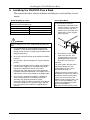
1
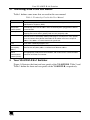
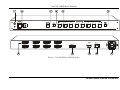
Kramer Electronics, Ltd.
USER MANUAL
Model:
VS-81DVI-R
8x1 DVI Switcher
Contents
Contents
1
2
3
3.1
4
5
6
6.1
6.2
Introduction
Getting Started
Overview
Terminology Used in this User Manual
Your VS-81DVI-R 8x1 Switcher
Installing the VS-81DVI-R on a Rack
Connecting a VS-81DVI-R 8x1 DVI Switcher
Controlling via RS-232 (for example, using a PC)
Controlling the VS-81DVI-R via the ETHERNET Port
1
1
2
3
3
6
7
9
10
6.2.1
6.2.2
Connecting the ETHERNET Port directly to a PC (Crossover Cable)
Connecting the ETHERNET Port via a Network Hub (Straight-Through Cable)
10
12
6.3
Configuring the Ethernet Port
12
6.3.1
6.3.2
Setting a Virtual Port
Setting an Ethernet Connection
14
15
7
Technical Specifications
16
Figures
Figure 1: VS-81DVI-R 8x1 DVI Switcher
Figure 2: Connecting a VS-81DVI-R 8x1 DVI Switcher
Figure 3: Connecting a PC without using a Null-modem Adapter
Figure 4: RJ-45 PINOUT
Figure 5: Local Area Connection Properties Window
Figure 6: Internet Protocol (TCP/IP) Properties Window
Figure 7: The Ethernet Configuration Manager Window
Figure 8: The Virtual Serial Port Manager Window
Figure 9: The Virtual Serial Port Properties Window
Figure 10: The Virtual Serial Port Properties Window (COM 3 and COM 4)
Figure 11: The Port Window – Selecting a Virtual Serial Port
Figure 12: The Port Window – Selecting a Remote Connection
4
8
9
10
11
11
13
14
14
15
15
15
Tables
Table 1: Terminology Used in this User Manual
Table 2: VS-81DVI-R 8x1 DVI Switcher Front Panel Features
Table 3: VS-81DVI-R 8x1 DVI Switcher Rear Panel Features
Table 4: Crossover Cable RJ-45 PINOUT
Table 5: Straight-through Cable RJ-45 PINOUT
Table 6: Ethernet Configuration Manager Window Functionality
Table 7: Technical Specifications of the VS-81DVI-R
3
5
5
10
12
13
16
i
ADDENDUM: VS-81DVI-R
This addendum outlines three changes to the VS-81DVI-R user manual:
First change:
On page 5, Table 2, item 3 is replaced as follows:
3
SELECTED INPUT 7-segment Display
Displays the selected input that is currently switched to
1
the output
Second change:
On page 15, before section 7, a new section is added “6.4 Acquiring the
EDID”, which includes the following text:
To acquire the EDID, do the following:
1. Turn the POWER off.
2. Press both the PANEL LOCK button and the INPUT SELECTOR 8 button at
the same time while turning the POWER on again.
The front panel display initially shows a blinking “E” followed by the input
numbers from 1 to 8 that blink, until the unit has completed reading the EDID.
While the machine is acquiring the EDID, do not press any button and do not
turn the power off
3.
Release the PANEL LOCK button and the INPUT 8 button.
If an output was connected, the output EDID is read at each input. If an output
was not connected, the default EDID is read at each input.
The default EDID settings are:
Max. resolution – 1600x1200; Max. frequency – 60Hz.
Third change:
You can download the Kramer Protocol 2000 from our Web site at:
http://www.kramerelectronics.com
1 If an acceptor is not connected to the output, the SELECTED INPUT 7-segment Display shows a dot beside the selected
input number
P/N: 2900 - 0001111
A1
Introduction
1
Introduction
Welcome to Kramer Electronics (since 1981): a world of unique, creative and
affordable solutions to the infinite range of problems that confront the video,
audio and presentation professional on a daily basis. In recent years, we have
redesigned and upgraded most of our line, making the best even better! Our
350-plus different models now appear in 8 Groups1, which are clearly defined
by function.
Congratulations on purchasing your Kramer VS-81DVI-R 8x1 DVI Switcher.
The VS-81DVI-R is ideal for conference room presentations and advertising
applications, as well as for rental and staging.
Each package includes the following items:
VS-81DVI-R 8x1 DVI Switcher
Power cord and Null-modem adapter
Windows®-based Kramer control software2
Windows®-based Ethernet Configuration Manager and Virtual Serial Port
Manager
Kramer RC-IR1 Infra-Red Remote Control Transmitter3 (including the
required battery and a separate user manual4)
Power cord
This user manual4
2
Getting Started
We recommend that you:
Unpack the equipment carefully and save the original box and packaging
materials for possible future shipment
Review the contents of this user manual
Use Kramer high performance high resolution DVI cables5
1 GROUP 1: Distribution Amplifiers; GROUP 2: Video and Audio Switchers, Matrix Switchers and Controllers; GROUP 3:
Video, Audio, VGA/XGA Processors; GROUP 4: Interfaces and Sync Processors; GROUP 5: Twisted Pair Interfaces;
GROUP 6: Accessories and Rack Adapters; GROUP 7: Scan Converters and Scalers; and GROUP 8: Cables and Connectors
2 Downloadable from our Web site at http://www.kramerelectronics.com
3 Previously known as the IR-1 / IR-1-01
4 Download up-to-date Kramer user manuals from our Web site at http://www.kramerelectronics.com
5 The complete list of Kramer cables is on our Web site at http://www.kramerelectronics.com
1
Overview
3
Overview
The VS-81DVI-R is a technologically advanced, high quality 8x1 switcher for
DVI-D signals supporting the DDWG DVI 1.0 standard.
With a bandwidth of 1.65GHz, the VS-81DVI-R can switch signals having
resolutions up to UXGA, including all HDTV formats. Since high-resolution DVI
signals are very sensitive to cable quality and to PCB layout, the VS-81DVI-R
uses a carefully designed PCB, which includes all buffering, conditioning and
amplifying circuitry to provide a reclocked top-notch output signal.
In addition the VS-81DVI-R:
Includes DVI-I connectors to make it compatible with all types of DVI cables
Features 8 input selector buttons, which automatically light up when the unit
detects an active signal on those inputs.
Includes a built-in reclocking block that regenerates the DVI signal, so
that several units may be cascaded
Automatically reads and stores, in non-volatile memory, the EDID1 block
of the display device
Does not support HDCP (High Definition Digital Content Protection)
Includes a MUTE button to disconnect the output and a PANEL LOCK
button to prevent unwanted tampering with the buttons on the front panel
Fits in one vertical space of a standard 19” professional rack enclosure
Control the VS-81DVI-R using the front panel buttons, or remotely via:
RS-232 serial commands transmitted by a touch screen system, PC, or
other serial controller
The Kramer infra-red remote control transmitter
The ETHERNET
To achieve the best performance:
Connect only good quality connection cables, thus avoiding interference,
deterioration in signal quality due to poor matching, and elevated noise
levels (often associated with low quality cables)
Avoid interference from neighboring electrical appliances that may
adversely influence signal quality and position your Kramer VS-81DVI-R
away from moisture, excessive sunlight and dust
1 EDID is Extended Display Identification Data
2
KRAMER: SIMPLE CREATIVE TECHNOLOGY
Your VS-81DVI-R 8x1 Switcher
3.1 Terminology Used in this User Manual
Table 1 defines some terms that are used in this user manual.
Table 1: Terminology Used in this User Manual
Term
802.3
Definition
The standard specification for ETHERNET that is maintained by the Institute of Electrical
and Electronics Engineers (IEEE).
Dynamic Host
Allows the network administrator to distribute IP addresses from a central point and
Configuration
automatically send a new IP address when an Ethernet point is plugged into a different
Protocol (DHCP)
network location
Gateway
A network position serving as an entry to another network. On the Internet, a node or
stopping point can be either a gateway node or a host (end-point) node.
IP Address
A 32-binary digit number that identifies each sender or receiver (within a network via a
particular server or workstation) of data (HTML pages or e-mails) that is sent in packets
across the Internet. Every device connected to an IP network must have a unique IP
address. This address is used to reference the specific unit.
Local Area Network Computers sharing a common communications line or wireless link, which often share a
(LAN)
server within a defined geographic area.
Media Access
A computer's unique hardware number (or address) in a LAN or other network. On an
Control (MAC)
Ethernet LAN, the (MAC) address is identical to the Ethernet address.
Address
Transmission
The basic communication language or protocol of the Internet that breaks the message
Control
into appropriately sized packets for the network, and can be used as a communications
Protocol/Internet
protocol in an intranet or an extranet.
Protocol (TCP/IP)
4
Your VS-81DVI-R 8x1 Switcher
Figure 1 illustrates the front and rear panels of the VS-81DVI-R. Table 2 and
Table 3 define the front and rear panels of the VS-81DVI-R, respectively.
3
Your VS-81DVI-R 8x1 Switcher
Figure 1: VS-81DVI-R 8x1 DVI Switcher
4
KRAMER: SIMPLE CREATIVE TECHNOLOGY
Your VS-81DVI-R 8x1 Switcher
Table 2: VS-81DVI-R 8x1 DVI Switcher Front Panel Features
#
1
Feature
IR Receiver
2
3
POWER Switch
SELECTED INPUT 7-segment Display
4
5
6
MUTE Button
INPUT SELECTOR Buttons
PANEL LOCK Button
Function
The red LED lights when receiving signals from the
Infra-red remote control transmitter
Illuminated switch for turning the unit ON or OFF
Displays the selected input that is currently switched to
the output
Press to disconnect the output
1
Press the INPUT button (1 to 8) to select input
Press to disengage the front panel buttons
Table 3: VS-81DVI-R 8x1 DVI Switcher Rear Panel Features
#
7
8
9
10
11
Feature
INPUT DVI-I Connectors
OUTPUT DVI-I Connector
RS-232 DB 9F Port
ETHERNET Connector
Power Connector with Fuse
Function
Connect to the DVI-D sources (from 1 to 8)
Connect to the DVI-D acceptor
Connects to the PC or the RS-232 Remote Controller
Connects to the PC or other Ethernet Controller
AC connector enabling power supply to the unit
1 The input buttons automatically illuminate when the unit detects an active signal on that input. For example, if inputs 4, 6
and 7 are connected and active, the INPUT SELECTOR buttons 4, 6 and 7 illuminate
5
Installing the VS-81DVI-R on a Rack
5
Installing the VS-81DVI-R on a Rack
This section describes what to do before installing on a rack and how to rack
mount.
Before Installing on a Rack
Before installing on a rack, be sure that the environment is
within the recommended range:
Operating temperature range +5 to +45 Deg. Centigrade
Operating humidity range
5 to 65 % RHL, non-condensing
Storage temperature range
-20 to +70 Deg. Centigrade
Storage humidity range
5 to 95% RHL, non-condensing
How to Rack Mount
To rack-mount the machine:
1
Attach both ear brackets to the
machine. To do so, remove the
screws from each side of the
machine (3 on each side), and
replace those screws through
the ear brackets.
CAUTION!!
When installing on a 19" rack, avoid hazards by taking care
that:
1
It is located within the recommended environmental
conditions, as the operating ambient temperature of a
closed or multi unit rack assembly may exceed the room
ambient temperature.
2
Once rack mounted, enough air will still flow around the
machine.
3
The machine is placed straight in the correct horizontal
position.
4
You do not overload the circuit(s). When connecting the
machine to the supply circuit, overloading the circuits
might have a detrimental effect on overcurrent
protection and supply wiring. Refer to the appropriate
nameplate ratings for information. For example, for fuse
replacement, see the value printed on the product label.
5
6
The machine is earthed (grounded) in a reliable way
and is connected only to an electricity socket with
grounding. Pay particular attention to supply
connections other than direct connections to the branch
circuit (for example, the use of power strips), and that
you use only the power cord that is supplied with the
machine.
2
Place the ears of the machine
against the rack rails, and
insert the proper screws (not
provided) through each of the
four holes in the rack ears.
Note that:
In some models, the front panel
may feature built-in rack ears
Detachable rack ears can be
removed for desktop use
Always mount the machine in the
rack before you attach any cables or
connect the machine to the power
If you are using a Kramer rack
adapter kit (for a machine that is not
19"), see the Rack Adapters user
manual for installation instructions
(you can download it at:
http://www.kramerelectronics.com)
KRAMER: SIMPLE CREATIVE TECHNOLOGY
Connecting a VS-81DVI-R 8x1 DVI Switcher
6
Connecting a VS-81DVI-R 8x1 DVI Switcher
To connect the VS-81DVI-R 8x1 DVI Switcher (as illustrated in Figure 2), do
the following1:
1. Connect up to 8 DVI sources (for example, DVI computer graphics sources)
to the INPUT connectors.
2. Connect the OUTPUT connector to the DVI acceptor (for example, a DVI
display).
3. If required, connect a PC and/or controller to the RS-232 port (see section 6.1)
and/or the ETHERNET port (see section 6.2).
4. Connect the power connector to the mains electricity.
After turning on the power, press an INPUT SELECTOR button (1 to 8) to
choose which DVI input to route to the output2.
1 Switch OFF the power on each device before connecting it to your VS-81DVI-R. After connecting your VS-81DVI-R,
switch on its power and then switch on the power on each device
2 If the input is connected and active, the respective input button illuminates
7
Connecting a VS-81DVI-R 8x1 DVI Switcher
RS-232
DVI Display
DVI
Graphics Source 1
DVI
Graphics Source 8
Figure 2: Connecting a VS-81DVI-R 8x1 DVI Switcher
8
KRAMER: SIMPLE CREATIVE TECHNOLOGY
Connecting a VS-81DVI-R 8x1 DVI Switcher
6.1 Controlling via RS-232 (for example, using a PC)
To connect a PC to the VS-81DVI-R unit, using the Null-modem adapter
provided with the machine (recommended):
Connect the RS-232 DB9 rear panel port on the Master VS-81DVI-R unit
to the Null-modem adapter and connect the Null-modem adapter with a
9-wire flat cable to the RS-232 DB9 port on your PC
To connect a PC to the VS-81DVI-R unit, without using a Null-modem adapter:
Connect the RS-232 DB9 port on your PC to the RS-232 DB9 rear panel
port on the Master VS-81DVI-R unit, as Figure 3 illustrates
PIN 5 Connected to PIN 5 (Ground)
PIN 3 Connected to PIN 2
PIN 2 Connected to PIN 3
Female DB9 (From PC)
Male DB9
PIN 4 Connected to PIN 6
PINS 8, 7, 1 Connected together
If a Shielded cable is used, connect the shield to PIN 5
Figure 3: Connecting a PC without using a Null-modem Adapter
9
Connecting a VS-81DVI-R 8x1 DVI Switcher
6.2 Controlling the VS-81DVI-R via the ETHERNET Port
You can connect the VS-81DVI-R via the Ethernet, using a crossover cable
(see section 6.2.1) for direct connection to the PC or a straight through cable
(see section 6.2.2) for connection via a network hub or network router.
6.2.1
Connecting the ETHERNET Port directly to a PC (Crossover Cable)
You can connect the Ethernet port of the VS-81DVI-R to the Ethernet port on
your PC, via a crossover cable with RJ-45 connectors, as Table 4 and Figure 4
define.
Figure 4: RJ-45 PINOUT
Table 4: Crossover Cable RJ-45 PINOUT
EIA /TIA 568A
Side 1
PIN Wire Color
1
White-orange
2
Orange
3
White-green
4
Blue
5
White-blue
6
Green
7
White-brown
8
Brown
EIA /TIA 568B
Side 2
PIN
Wire Color
1
White-green
2
Green
3
White-orange
4
Blue
5
White-blue
6
Orange
7
White-brown
8
Brown
Pair 1
4 and 5
Pair 1
Pair 2
1 and 2
Pair 2
3 and 6
Pair 3
3 and 6
Pair 3
1 and 2
Pair 4
7 and 8
Pair 4
7 and 8
4 and 5
This type of connection is recommended for identification of the factory default
IP Address of the VS-81DVI-R during the initial configuration
After connecting the Ethernet port, configure your PC as follows:
1. Right-click the My Network Places icon on your desktop.
2. Select Properties.
3. Right-click Local Area Connection Properties.
4. Select Properties.
The Local Area Connection Properties window appears.
10
KRAMER: SIMPLE CREATIVE TECHNOLOGY
Connecting a VS-81DVI-R 8x1 DVI Switcher
5. Select the Internet Protocol (TCP/IP) and click the Properties Button (see
Figure 5).
Figure 5: Local Area Connection Properties Window
6. Select Use the following IP Address, and fill in the details as shown in
Figure 6.
7. Click OK.
Figure 6: Internet Protocol (TCP/IP) Properties Window
11
Connecting a VS-81DVI-R 8x1 DVI Switcher
6.2.2
Connecting the ETHERNET Port via a Network Hub (Straight-Through
Cable)
You can connect the Ethernet port of the VS-81DVI-R to the Ethernet port on
a network hub or network router, via a straight-through cable with RJ-45
connectors, as Table 5 defines:
Table 5: Straight-through Cable RJ-45 PINOUT
Side 1
PIN
1
2
3
4
5
6
7
8
Wire Color
White-orange
Orange
White-green
Blue
White-blue
Green
White-brown
Brown
Side 2
PIN
1
2
3
4
5
6
7
8
Wire Color
White-orange
Orange
White-green
Blue
White-blue
Green
White-brown
Brown
6.3 Configuring the Ethernet Port
To configure the ETHERNET port, do the following:
1. Connect the ETHERNET port as described in section 6.2.1.
2. Insert the CD-ROM in the CD-ROM drive, double click the SetFC11_xx.exe1
file and follow the on-screen instructions2.
Both the Ethernet Configuration Manager and the Virtual Serial Port Manager
are downloaded.
3. Click the appropriate shortcut in the Start menu’s Programs folder. The
Configuration Manager window (see Figure 7) opens.
4. Click the Search button3 (or the Action menu’s, Search Board command).
The MAC Address for the found ETHERNET port appears in the Device List.
5. Change the settings according to your network requirements and then click the
Config button (or the Action menu’s, Config command) to apply the settings.
Note that clicking the Config button will alter the IP settings of the ETHERNET
port
1 File names are liable to change from time to time
2 The latest version appears on our Web site at http://www.kramerelectronics.com
3 To automatically search for devices
12
KRAMER: SIMPLE CREATIVE TECHNOLOGY
Connecting a VS-81DVI-R 8x1 DVI Switcher
Figure 7: The Ethernet Configuration Manager Window
Table 6: Ethernet Configuration Manager Window Functionality
Feature
File
Menu bar
#
1
Function
The Exit command closes the Configuration Manager application
Set MAC1
The Search Board command seeks the VS-81DVI-R device that connects to the PC via
the ETHERNET port, and displays it and its corresponding settings;
The Config command adjusts the VS-81DVI-R according to the displayed data
For factory use only (click the Password command to enter the password)
About
Displays software information, including the software version
Action
2
3
4
5
6
Device List
Progress Bar
Status Bar
Version
Device Network
Settings Area
7
8
Exit Button
Action Buttons
Displays the MAC Address
Shows the progress
Shows the status
Displays the firmware version
DHCP1 Mode Check Box: When selected, configures the Ethernet port to obtain an IP
address automatically from the DHCP server. When cleared, manual configuration of
the Ethernet port is required to obtain an IP address (Static IP)
IP Address: A 32-binary digit number obtained from your Network Administrator that
identifies the Ethernet port that is currently being configured
Subnet: A 32-binary digit number obtained from your Network Administrator, which
combined with the IP Address, identifies which network your device is on
Gateway: A network position serving as an entry to another network or to the Internet
(only relevant in the Active Routing mode)
Closes the Configuration Manager application
Search: seeks the devices that connect to the PC via the ETHERNET port, and
displays them and their corresponding settings
Config: adjusts the according to the displayed data
1 See the definition in Table 1
13
Connecting a VS-81DVI-R 8x1 DVI Switcher
6.3.1
Setting a Virtual Port
If the control application cannot work with an Ethernet driver, use the Kramer
Virtual port driver as follows:
1. Run the Virtual Serial Port Manager Application.
The Virtual Serial Port Manager window appears (see Figure 8).
Figure 8: The Virtual Serial Port Manager Window
2. Press the Add VSP button to add a serial port and type the IP settings
according to the IP address and local port of your VS-8DVI-R (see Figure 9).
Figure 9: The Virtual Serial Port Properties Window
3. You can set a virtual port for each local port on your VS-8DVI-R (see Figure
10).
14
KRAMER: SIMPLE CREATIVE TECHNOLOGY
Connecting a VS-81DVI-R 8x1 DVI Switcher
Figure 10: The Virtual Serial Port Properties Window (COM 3 and COM 4)
4. In the control application, choose the COM-port connection according to your
virtual serial port connections (see Figure 11).
Figure 11: The Port Window – Selecting a Virtual Serial Port
6.3.2
Setting an Ethernet Connection
If the control application can directly connect to the Ethernet driver, select the
host IP and port number, as illustrated in Figure 12.
Figure 12: The Port Window – Selecting a Remote Connection
15
Technical Specifications
7
Technical Specifications
Table 7 includes the technical specifications:
1
Table 7: Technical Specifications of the VS-81DVI-R
INPUTS:
OUTPUT:
RESOLUTION:
POWER SOURCE:
CONTROLS:
DIMENSIONS:
WEIGHT:
ACCESSORIES:
2
8 DVI-D , 1.2Vpp on DVI Molex 24pin female connectors; DDC signal 5Vpp (TTL)
1 DVI-D2, 1.2Vpp on a DVI Molex 24pin female connector; DDC signal 5Vpp (TTL)
Up to UXGA
100 264VAC; 50/60Hz
Front panel buttons, Infra-red remote control transmitter, RS-232, Ethernet
19-inch (W), 7-inch (D), 1U (H)
2.5 kg. (5.5 lbs.) approx.
3
Power cord , Null modem adapter, IR remote control transmitter, Windows®-based
software
1 Specifications are subject to change without notice
2 On a DVI-I connector. Note that only the digital signal (DVI-D) is available on the DVI connector
3 We recommend that you use only the power cord that is supplied with this machine
16
KRAMER: SIMPLE CREATIVE TECHNOLOGY
LIMITED WARRANTY
Kramer Electronics (hereafter Kramer) warrants this product free from defects in material and workmanship under the
following terms.
HOW LONG IS THE WARRANTY
Labor and parts are warranted for seven years from the date of the first customer purchase.
WHO IS PROTECTED?
Only the first purchase customer may enforce this warranty.
WHAT IS COVERED AND WHAT IS NOT COVERED
Except as below, this warranty covers all defects in material or workmanship in this product. The following are not covered
by the warranty:
1.
2.
3.
Any product which is not distributed by Kramer, or which is not purchased from an authorized Kramer dealer. If you are
uncertain as to whether a dealer is authorized, please contact Kramer at one of the agents listed in the Web site
www.kramerelectronics.com.
Any product, on which the serial number has been defaced, modified or removed.
Damage, deterioration or malfunction resulting from:
i)
Accident, misuse, abuse, neglect, fire, water, lightning or other acts of nature
ii)
Product modification, or failure to follow instructions supplied with the product
iii)
Repair or attempted repair by anyone not authorized by Kramer
iv)
Any shipment of the product (claims must be presented to the carrier)
v)
Removal or installation of the product
vi)
Any other cause, which does not relate to a product defect
vii)
Cartons, equipment enclosures, cables or accessories used in conjunction with the product
WHAT WE WILL PAY FOR AND WHAT WE WILL NOT PAY FOR
We will pay labor and material expenses for covered items. We will not pay for the following:
1.
2.
3.
Removal or installations charges.
Costs of initial technical adjustments (set-up), including adjustment of user controls or programming. These costs are the
responsibility of the Kramer dealer from whom the product was purchased.
Shipping charges.
HOW YOU CAN GET WARRANTY SERVICE
1.
2.
3.
To obtain service on you product, you must take or ship it prepaid to any authorized Kramer service center.
Whenever warranty service is required, the original dated invoice (or a copy) must be presented as proof of warranty coverage,
and should be included in any shipment of the product. Please also include in any mailing a contact name, company, address, and
a description of the problem(s).
For the name of the nearest Kramer authorized service center, consult your authorized dealer.
LIMITATION OF IMPLIED WARRANTIES
All implied warranties, including warranties of merchantability and fitness for a particular purpose, are limited in duration to
the length of this warranty.
EXCLUSION OF DAMAGES
The liability of Kramer for any effective products is limited to the repair or replacement of the product at our option. Kramer
shall not be liable for:
1.
2.
Damage to other property caused by defects in this product, damages based upon inconvenience, loss of use of the product, loss
of time, commercial loss; or:
Any other damages, whether incidental, consequential or otherwise. Some countries may not allow limitations on how long an
implied warranty lasts and/or do not allow the exclusion or limitation of incidental or consequential damages, so the above
limitations and exclusions may not apply to you.
This warranty gives you specific legal rights, and you may also have other rights, which vary from place to place.
NOTE: All products returned to Kramer for service must have prior approval. This may be obtained from your dealer.
This equipment has been tested to determine compliance with the requirements of:
EN-50081:
"Electromagnetic compatibility (EMC);
generic emission standard.
Part 1: Residential, commercial and light industry"
EN-50082:
"Electromagnetic compatibility (EMC) generic immunity standard.
Part 1: Residential, commercial and light industry environment".
CFR-47:
FCC Rules and Regulations:
Part 15: “Radio frequency devices
Subpart B – Unintentional radiators”
CAUTION!
Servicing the machines can only be done by an authorized Kramer technician. Any user who makes changes or modifications to
the unit without the expressed approval of the manufacturer will void user authority to operate the equipment.
Use the supplied DC power supply to feed power to the machine.
Please use recommended interconnection cables to connect the machine to other components.
17
For the latest information on our products and a list of Kramer
distributors, visit our Web site: www.kramerelectronics.com,
where updates to this user manual may be found.
We welcome your questions, comments and feedback.
Safety Warning:
Disconnect the unit from the power supply before
opening/servicing.
Caution
Kramer Electronics, Ltd.
Web site: www.kramerelectronics.com
E-mail: [email protected]
P/N: 2900-000111 REV 1A