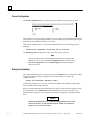
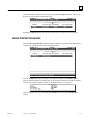
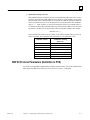
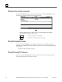
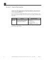
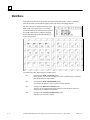
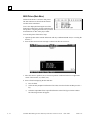
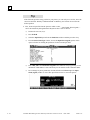
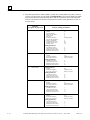
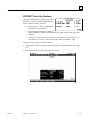
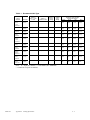
1
GE Fanuc Automation
Programmable Control Products
PANELWARE™ MMI Application Manual
for GE Fanuc Genius™ Protocol
User's Manual
GFK - 1115
June 1995
GFL-002
Warnings, Cautions, and Notes
as Used in this Publication
Warning
Warning notices are used in this publication to emphasize that hazardous voltages, currents,
temperatures, or other conditions that could cause personal injury exist in this equipment or
may be associated with its use.
In situations where inattention could cause either personal injury or damage to equipment, a
Warning notice is used.
Caution
Caution notices are used where equipment might be damaged if care is not taken.
Note
Notes merely call attention to information that is especially significant to understanding and
operating the equipment.
This document is based on information available at the time of its publication. While efforts have been
made to be accurate, the information contained herein does not purport to cover all details or variations in
hardware or software, nor to provide or every possible contingency in connection with installation,
operation, or maintenance. Features may be described herein which are not present in all hardware and
software systems. GE Fanuc Automation assumes no obligation of notice to holders of this document with
respect to changes subsequently made.
GE Fanuc Automation makes no representation or warranty, expressed, implied, or statutory with respect
to, and assumes no responsibility for the accuracy, completeness, sufficiency, or usefulness of the
information contained herein. No warranties of merchantability or fitness for purpose shall apply.
The following are trademarks of GE Fanuc Automation North America, Inc.
Alarm Master
CIMPLICITY
CIMPLICITY
PowerTRAC
CIMPLICITY 90–ADS
CIMSTAR
Field Control
GEnet
Genius
Genius PowerTRAC
Helpmate
Logicmaster
Modelmaster
ProLoop
PROMACRO
Series Five
Series 90
Series One
Series Six
Series Three
VuMaster
Workmaster
©Copyright 1995 GE Fanuc Automation North America, Inc.
All Rights Reserved.
Preface
This manual provides a quick guide to installing and operating PANELWARE™ Panels,
describes configuration techniques, and outlines general use of the PANELWARE Configuration
Software (PCS) with GE Fanuc Genius Protocol.
Some of the products mentioned or illustrated in this manual may not be released when this
document is published. Please do not rely on any references made to these units. Your local
GE Fanuc distributor will inform you of any new product releases.
Content of This Manual
Chapter 1. Overview provides a short description of the PCS and outlines the prerequisites for
PCS operation with the PC and the PLC.
Chapter 2. C400 Panel Controller Hardware provides specifications, descriptions of
connections and operational elements, and operating instructions for the C400 Controller.
Chapter 3. Quick Start provides installation instructions and introduces the operation and
functionality of the PCS by means of several easy-to-follow examples.
Chapter 4. Configuring Communication with the PLC contains information on Panel
Controller and PLC interface configurations and describes how to make the connection between
the Panel and PLC.
Chapter 5. Connection Editor describes the PCS function that performs the organization of
variables in the Panel (symbolic names) and addresses in the PLC.
Chapter 6. Demo Project briefly explains how to run the demo projects that are delivered with
the software.
Appendix A. Cabling Information describes the required PCS to PLC and PC interface cables
and provides several cabling diagrams.
Appendix B. Errors / Troubleshooting provides an overview of possible system errors and
explains their causes and possible solutions.
GFK-1115
iii
Preface
Related Publications
PANELWARE Manuals
GFK-0848
PANELWARE™ Hardware Installation User's Manual
Describes the PANELWARE Operator Panels and contains technical data, hardware installation
instructions, and the general information required for putting the Panels into operation.
GFK-0849
PANELWARE™ Configuration Software Reference Manual
Describes the PANELWARE Configuration Software and provides the program setups for Panels
that are equipped with a programmable controller.
GFK-0850
PANELWARE™ MMI Application Manual for GE Fanuc Series 90™
Protocol (SNP)
Contains specific information on the configuration of PANELWARE Panels that communicate by
means of GE Fanuc Series 90 Protocol.
GFK-1112
PANELWARE™ Application Manual for Siemens SINEC L1 Driver
Contains specific information on the configuration of PANELWARE Panels that communicate
with Siemens controllers by means of the SINEC L1 protocol.
GFK-1113
PANELWARE™ Application Manual for the Modicon MODBUS
(RTU/ASCII) Driver
Contains specific information on the configuration of PANELWARE Panels that communicate
with MODICON controllers by means of the MODBUS protocol.
GFK-1142
PANELWARE™ Configuration Software Quick Start Guide
This guide, a companion to the PANELWARE Configuration Software Reference Manual (GFK0849), provides basic information for configuring and using PCS.
Other Documents
GEK-90486-1 Genius™ I/O System and Communications User’s Manual
Reference manual for systems designers, programmers, and others involved in integrating Genius
I/O products in a PLC or host computer environment. This book provides a system overview, and
describes the types of systems that can be created using Genius products. Datagrams, global data,
and data formats are defined.
GFK-0398
Series 90™-70 Genius™- Bus Controller User’s Manual
Describes the features and operation of the Series 90-70 Genius Bus Controller. Provides
configuration and programming information needed to complete the interface between a Series
90-30 PLC and a Genius I/O Bus.
GFK-0585
Series 90 PLC SNP Communications Driver User’s Manual
Describes the software installation, operation, and programming of the GE Fanuc Series 90
Protocol Driver. The SNP is used to retrieve/store data or issue commands to a given Series 90
PLC via the serial port.
iv
PANELWARE MMI Application Manual for GE Fanuc Genius Protocol - June 1995
GFK-1115
Preface
GFK-0852
Series 90™ PLC Serial Communications User's Manual
This manual describes serial communications products for the Series 90 Programmable Logic
Controller. Information is provided to implement a serial communications link between the Series
90 PLC, a host computer, peripheral device, or another PLC.
GFK-0898
Series 90-30 Programmable Controller I/O Module Specifications
Describes the discrete and analog I/O modules for the GE Fanuc Series 90-30 PLC. Contains
descriptions of each I/O module and provides specifications and wiring information for each
module.
GFK-1034
Series 90™-30 Genius™ Bus Controller User’s Manual
Describes the features and operation of the Series 90-30 Genius Bus Controller. Provides
configuration and programming information needed to complete the interface between a Series
90-30 PLC and a Genius I/O Bus.
We Welcome Your Comments and Suggestions
At GE Fanuc Automation, we strive to produce quality technical documentation. After you have
used this manual, please take a few moments to complete and return the Reader's Comment Card
located on the next page.
Libby Allen
Senior Technical Writer
GFK-1115
Preface
v
Contents
Chapter 1
Overview ............................................................................................................... 1-1
PANELWARE Configuration Software.............................................................................. 1-2
Hardware and Software Requirements ................................................................................ 1-3
PLC Requirements ............................................................................................................. 1-4
Document Conventions....................................................................................................... 1-5
Key Symbols ............................................................................................................... 1-5
Menu Functions ........................................................................................................... 1-5
Chapter 2
C400 Panel Controller Hardware......................................................................... 2-1
General Information ........................................................................................................... 2-2
Power Requirement...................................................................................................... 2-2
Connecting Power to the Controller .............................................................................. 2-2
Setting Number Switches ............................................................................................. 2-2
Genius Panel Controller (C400).......................................................................................... 2-3
Specifications .............................................................................................................. 2-3
Overview of Connections and Operational Elements ..................................................... 2-5
Operating the C400 Controller ........................................................................................... 2-9
FlashPROM ................................................................................................................ 2-9
RESET Modes............................................................................................................. 2-9
Loading and Starting Panel Programs......................................................................... 2-10
Update Mode/Reloading the Operating System ........................................................... 2-10
Chapter 3
Quick Start............................................................................................................ 3-1
Section 1 Software Installation ............................................................................ 3-2
Calling the Setup Program.................................................................................................. 3-2
Language Selection ............................................................................................................ 3-2
Installation Menu ............................................................................................................... 3-3
Changing the Destination Path ..................................................................................... 3-3
Start Installation .......................................................................................................... 3-3
Screen Configuration ................................................................................................... 3-4
Exiting the Installation ................................................................................................. 3-4
Section 2 Starting PCS......................................................................................... 3-5
Section 3 General Operation ............................................................................... 3-6
Pull-Down Menus (Main Menu)......................................................................................... 3-6
Window Name ................................................................................................................... 3-6
Selection Windows............................................................................................................. 3-7
Context-Sensitive Help Screens .......................................................................................... 3-7
Screen Elements................................................................................................................. 3-8
Section 4 PCS Configuration............................................................................... 3-9
GFK-1115
vii
Contents
Section 5 Creating a New Project.......................................................................3-10
Section 6 Defining Connections..........................................................................3-13
Connection to a GE Fanuc PLC via Genius ...................................................................... 3-14
Internal Connection .......................................................................................................... 3-17
Genius Internal Connection .............................................................................................. 3-18
Section 7 Key Assignments.................................................................................3-19
Section 8 Creating Pictures ................................................................................3-21
Picture 1 .......................................................................................................................... 3-21
Picture 2 .......................................................................................................................... 3-25
Picture 3 .......................................................................................................................... 3-27
Section 9 Defining the Project Variables............................................................3-28
Genius Device Connection................................................................................................ 3-29
Genius Internal Connection .............................................................................................. 3-30
Internal Connection .......................................................................................................... 3-31
Section 10 Binding Pictures in the Project.........................................................3-32
Picture for a Communications Error ................................................................................. 3-33
Picture Binding Overview................................................................................................. 3-34
Error Picture.............................................................................................................. 3-35
Start-up Picture ......................................................................................................... 3-36
Pict_1........................................................................................................................ 3-37
Picture List Organization ................................................................................................. 3-38
Section 11 Compiling the Project .......................................................................3-39
Section 12 Downloading the Project to the Panel ..............................................3-40
Section 13 Connecting the PLC and the Panel ..................................................3-42
Section 14 Starting the Project...........................................................................3-43
Section 15 Exiting PCS .......................................................................................3-44
Chapter 4
Configuring Communication with the PLC......................................................... 4-1
Genius Protocol Parameters (Definition in PCS) ................................................................. 4-2
PLC Types .................................................................................................................. 4-3
PLC Node Parameter Definitions ................................................................................. 4-5
PLC Network Parameter Definitions ............................................................................ 4-7
SNP 90 Protocol Parameters (Definition in PCS)................................................................ 4-9
Settings on the Panel ........................................................................................................ 4-10
Panel Interface ................................................................................................................. 4-10
Configuration of the PLC Interface................................................................................... 4-10
Chapter 5
PCS Connection Editor ........................................................................................ 5-1
General Information ........................................................................................................... 5-2
Accessing the Connection List ............................................................................................ 5-2
viii
PANELWARE MMI Application Manual for GE Fanuc Genius Protocol - June 1995
GFK-1115
Contents
Elements of the Connection List ......................................................................................... 5-3
Using Function Keys in the Connection List........................................................................ 5-3
Overview ..................................................................................................................... 5-3
Editing/Inserting Connections....................................................................................... 5-4
Defining/Changing an ID ............................................................................................. 5-4
Defining/Changing a Connection .................................................................................. 5-4
Deleting Connections ................................................................................................... 5-5
Editing PLC Node Parameters of a Connection............................................................. 5-5
Editing the Variable Assignment Table ............................................................................... 5-6
Elements of the VAT ................................................................................................... 5-6
Function Keys of the VAT ........................................................................................... 5-7
Editing/Inserting Variable Assignments ........................................................................ 5-8
Entering/Changing the Tagname................................................................................... 5-8
Entering/Changing PLC Addresses............................................................................... 5-8
Entering/Changing PLC Variable Types....................................................................... 5-9
Deleting Variable Assignments................................................................................... 5-10
Marking Unused Variables......................................................................................... 5-10
Global Data Format ......................................................................................................... 5-11
Data Type Conversions .................................................................................................... 5-12
Chapter 6
Demo Project......................................................................................................... 6-1
Section 1 General Information ............................................................................ 6-2
Section 2 Required Hardware ............................................................................. 6-3
Section 3 Downloading the Demo Project........................................................... 6-4
Defining the User Path ....................................................................................................... 6-4
Loading the Project ............................................................................................................ 6-5
Downloading and Starting the Project ................................................................................. 6-6
Section 4 Description of the Demo Project.......................................................... 6-7
General Information ........................................................................................................... 6-7
Main Menu ........................................................................................................................ 6-8
Value Entries ..................................................................................................................... 6-9
INPUT VALUES Picture............................................................................................. 6-9
CLOCK Picture......................................................................................................... 6-10
Entering a Password......................................................................................................... 6-11
INPUT PASSWORD Picture..................................................................................... 6-11
LOCKED INPUT Picture .......................................................................................... 6-12
Key Functions.................................................................................................................. 6-13
Alarm List ....................................................................................................................... 6-14
Error Picture.................................................................................................................... 6-15
Section 5 Creating the Demo Project .................................................................6-16
General Information ......................................................................................................... 6-16
GFK-1115
Table of Contents
ix
Contents
Creating a Project ............................................................................................................ 6-16
Preparing a Concept................................................................................................... 6-17
Creating a New Project .............................................................................................. 6-18
Selecting the Connections........................................................................................... 6-19
Defining Key Assignments ......................................................................................... 6-22
Creating the Pictures.................................................................................................. 6-23
Defining the Text Groups........................................................................................... 6-51
Binding Pictures to the Project ................................................................................... 6-52
Editing the Alarm System........................................................................................... 6-58
Activating the Alarm System...................................................................................... 6-60
Editing the Connections.............................................................................................. 6-61
Compiling the Project....................................................................................................... 6-64
Errors .............................................................................................................................. 6-64
Appendix A
Cabling Information ............................................................................................A-1
Genius Communications.................................................................................................... A-2
Selecting a Cable Type ............................................................................................... A-2
Using Other Cable Types ............................................................................................ A-2
Bus Length ................................................................................................................. A-4
Baud Rate Selection.................................................................................................... A-4
Connecting Devices to the Bus .................................................................................... A-5
SNP Communications ....................................................................................................... A-5
Cable Diagrams ................................................................................................................ A-6
Appendix B
Errors/Troubleshooting .......................................................................................B-1
Errors During Installation.................................................................................................. B-2
Errors During Program Start ............................................................................................. B-3
Errors While Working in PCS ........................................................................................... B-4
Error Numbers in Internal USER Variable......................................................................... B-6
x
PANELWARE MMI Application Manual for GE Fanuc Genius Protocol - June 1995
GFK-1115
Chapter
Overview
1
This chapter provides a short overview/description of the PANELWARE Configuration Software
(PCS) and outlines the requirements for PCS operation with the PC and PLC. It includes the
following information:
GFK-1115
■
PANELWARE Configuration Software (PCS) ............................................................1-2
■
Hardware and Software Requirements ........................................................................1-3
■
PLC Requirements......................................................................................................1-4
■
Document Conventions...............................................................................................1-5
1-1
1
PANELWARE Configuration Software
PANELWARE Configuration Software allows complex projects to be created, using easy-tofollow, menu-controlled instructions. These projects are actually programs that are transferred to a
Panel and started there via a Panel power-on or Reset. The PCS-created Panel program (project)
then takes over communication with the PLC and performs the following:
■
Reads data from the PLC and displays it on the screen in the specified format (values,
text, bar-graphs, graphics)
■
Writes data to the PLC and executes PLC functions
■
Displays static data, such as text masks and lines
Using PCS, projects can be created for the C400 Panel Controller.
Every project consists of at least the following components:
Table 1 - 1. PCS Project Component Descriptions
Project Component
1-2
Definition
Project Definition
Consists mainly of the hardware configuration of the Panel and the picture
directory.
Picture Directory
A list of all pictures used in the project; also contains information on
switching to other pictures.
A picture change (making a different picture appear on the screen) can be
performed either by pressing a defined key or via the direction of the PLC.
Pictures
Contains all information about what is to be displayed on the display
module. Text, in/output fields, and on graphics-capable displays, lines, and
bars, can all be components of a picture.
Keyboard Definition
Defines the keyboard function assignments (function keys, numeric, or
alphanumeric keys can be defined).
Connection List
Lists all connections that the Panel can access. A connection defines the
type of connection (protocol), the interface, and the location where the
Panel can find the data (e.g., which CPU in a network).
PANELWARE MMI Application Manual for GE Fanuc Genius Protocol - June 1995
GFK-1115
1
Hardware and Software Requirements
PCS is delivered on two 3½-inch disks in 2DD (720K) format and on one 5¼-inch disk in 2S/HD
(1.2M) format. The diskette(s) you use to install the PCS depends on your PC configuration.
Description
Catalog
Number
PANELWARE Configuration Software
(includes cable assembly)
IC641SWP950
Before starting the software installation, make sure the following requirements are met:
■
Complete IBM PC compatibility (processor types: 80286 and higher)
■
IBM compatible monochrome or color adapter
■
One 3½ inch (720 Kbyte) or 5¼ inch (1.2 Mbyte) floppy disk drive
■
For the installation, approximately 3 Mbytes must be free on the hard disk.
■
640 KB RAM, of which at least 512 KB must be available. Memory-resident programs
should be removed if necessary to free up the RAM.
■
Minimum 1 serial interface (COM1 or COM2)
■
MS-DOS version 3.30 or higher
■
The CONFIG.SYS file settings for FILES and BUFFERS must be set to a minimum of:
FILES=40; BUFFERS=10.
Note
PCS can be executed in a DOS box under Windows 3.1 only in offline mode. To
either download or upload a project to/from a Panel, you must exit Windows and
run PCS from the DOS prompt.
GFK-1115
Chapter 1 Overview
1-3
1
PLC Requirements
To communicate with the C400 Genius Panel Controller, the PLC must meet the following
requirements:
■
Series 90-70 PLC
❏
■
■
■
Series 90-30 PLC
❏
Genius Communications Module (GCM), IC693CMM301
❏
Enhanced Genius Communications Module (GCM+), IC693CMM302
❏
Genius Bus Controller, IC693BEM331
Series Six
❏
Genius Bus Controller with diagnostics, IC660CBB902
❏
Genius Bus Controller without diagnostics, IC660CBB903
Series Five
❏
1-4
Genius Bus Controller (GBC), IC697BEM731
Genius Bus Controller, IC655BEM510
PANELWARE MMI Application Manual for GE Fanuc Genius Protocol - June 1995
GFK-1115
1
Document Conventions
Key Symbols
All keys used to operate PCS are shown in bold in this manual:
Table 1 - 2. Key Symbols
Key
Description
German
English
↑
↑
Cursor up
↓
↓
Cursor down
←
←
Cursor left
→
→
Cursor right
↵
↵
Enter (Return)
Bild↑
↑
PgUp
Cursor one page up
Bild↓
↓
PgDn
Cursor one page down
Einfg
Ins
Switches between insert and overwrite modes
Entf
Del
The character in the cursor position is deleted
Esc
Esc
Exits from the current function; exits the editor or a menu
Space
Space
Strg
Ctrl
Control key
Shift
Shift
SHIFT key
Alt
Alt
Alternate key
⇐
⇐
The character to the left of the cursor position is deleted (Back Space)
Space (Blank character)
If two keys are to be pressed simultaneously in order to execute a function, the keys will be
connected by the plus (+) character. Example:
Ctrl
+
Ins
Text that is to be entered directly using the keyboard is shown in bold and italic. Example:
panel
Menu Functions
The names of pull-down menus and menu functions are shown in bold. Example:
Edit menu
GFK-1115
Chapter 1 Overview
1-5
Chapter
C400 Panel Controller Hardware
2
This chapter describes the C400 PANELWARE Panel Controller (IC750CTR400), its connections
(interfaces) and all operational elements for which hardware must be configured on the modular
Panel. The following sections of information are included:
■
■
■
GFK-1115
General Information ...................................................................................................2-2
❏
Power Requirement..............................................................................................2-2
❏
Connecting Power to the Controller .....................................................................2-2
❏
Setting Number Switches.....................................................................................2-2
Genius Panel Controller (C400)..................................................................................2-3
❏
Specifications ......................................................................................................2-3
❏
Overview of Connections and Operational Elements ............................................2-5
Operating the C400 Controller ...................................................................................2-7
❏
FlashPROM.........................................................................................................2-9
❏
RESET Modes .....................................................................................................2-9
❏
Loading and Starting Panel Programs................................................................2-10
❏
Update Mode/Reloading the Operating System ..................................................2-10
2-1
2
General Information
Power Requirement
24 VDC power must be supplied to the PANELWARE Controller unit. The Controller, in turn,
supplies the Keyblock and Display modules with power.
When estimating the total 24 VDC power consumption for a system, add up the 24 VDC power
supply requirements for all of the PANELWARE components being used, then add an additional
30% to allow for power on surge currents. Refer to the PANELWARE™ Hardware Installation
User’s Guide (GFK-0848) for details on displays and Keyblocks.
Connecting Power to the Controller
The 24 VDC power connector on the Controller is located on the top left corner of the unit. The
mating connector is supplied with each Controller.
Caution
Do not try to run PANELWARE off a Series 90-30 power supply revision M
or earlier. Although some configurations might function under this setup, it
is not recommended. Damage to the 90-30 power supply could result.
The suitability of a Series 90-30, revision N or later power supply depends
on the +24VDC isolated load requirements of the modules in your PLC.
Refer to the Series 90-30 Programmable Controller I/O Module
Specifications (GFK-0898) to determine additional load requirements of
your system.
All components of a PLC and the devices it is controlling must be properly grounded. This is
particularly important for the reasons listed below:
■
A low-resistance path from all parts of a system to ground minimizes exposure to shock
in the event of short circuits or equipment malfunction.
■
PANELWARE Operator Panels require proper grounding for correct operation.
The importance of grounding can not be over emphasized.
Setting Number Switches
Number switch settings on the Panel Controller can be set using a small flathead screwdriver to
turn the switch dial to the desired setting (so that the arrow points at the desired setting).
The assembled Panel configuration provides minimal space to reach the number switches once the
Panel is installed. If possible, these settings should be made before the Controller is installed.
2-2
PANELWARE MMI Application Manual for Genius Protocol - June 1995
GFK-1115
2
Genius Panel Controller (C400)
Specifications
a45517
SHLD IN
X2
X1
GENIUS
SHLD OUT
7.165"
(182mm)
2.165"
(55mm)
7.165"
(182mm)
Figure 2 - 1. Genius Panel Controller (C400)
Table 2 - 1. Specifications for Genius Panel Controller (C400)
Technical Data
Interfaces
IF0:
RS-232 (not galvanically isolated)
Genius: (isolated)
Programming
PANELWARE Configuration Software
Power supply
24 VDC (min. 18 VDC, max. 30 VDC)
Real-time clock
YES with battery installed (non-volatile)
Connection of ....
Display modules
Keyblock modules
1
maximum of 7
Temperature
Operating
Storage
0 to 50 °C (32 to 122 °F)
-20 to 60 °C (-4 to 140 °F)
Relative humidity
Operating
10 to 95 % (non-condensing)
Storage
GFK-1115
10 to 95 % (non-condensing)
Chapter 2 C400 Panel Controller Hardware
2-3
2
Table 2 - 1. - Continued
2-4
Shock
conforms to IEC 68-2-27
15g equivalent, 150 m/sec2, 11 msec, 3 axes (positive and
negative)
Vibration
conforms to IEC 68-2-6
1g equivalent,
10-58 Hz; 0.075 mm
58-150 Hz; 9.8m/sec2
20 cycles per axis
Processor
Motorola 68302 @ 16 MHz
24 VDC power
requirements
(typical)
185 mA, 24 VDC
260 mA, 18 VDC (minimum power voltage)
150 mA, 30 VDC (maximum power voltage)
Sealing
NEMA 12 and IP54 when properly mounted in a Panel
Noise immunity
conforms to IEC 801.2; IEC 801.3; IEC 801.4
PANELWARE MMI Application Manual for Genius Protocol - June 1995
GFK-1115
2
Overview of Connections and Operational Elements
a45516
1
2
9
8
3
7
6
4
5
Figure 2 - 2. Genius Panel Controller (C400) Elements/Connections
1. Display Module Connector (ribbon
cable)
GFK-1115
2.
24 VDC Power Supply Connector
3.
IF0: RS-232 (to PC), labeled 0
4.
Genius Bus Connector
5.
Keyblock Module Connector
Chapter 2 C400 Panel Controller Hardware
6.
Mode Switch - Operating Mode
7.
Cover for Lithium Battery
8.
Device Number Switches
9.
Reset Button
2-5
2
24 VDC Power Supply (item 2, Figure 2-2)
Pin
+
-
Description
+24 V
0V
Ground
Ground
The
pins are to be connected using as short a cable as is possible. If the Panel is mounted in a
cabinet, the connecting cable should be as short as possible.
IF0 - RS-232, Non-isolated (item 3, Figure 2-2)
Pin
1
9 pin D-Type (M)
LED
Meaning
TxD
Send data over interface
RxD
2-6
Receive data over interface
Description
NC
2
RxD
Receive Data (Input)
3
TxD
Transmit Data (Output)
4
+ 5 V Power Supply
(200 mA available to user)
5
GND Signal Ground
6
NC
7
RTS
Request To Send (Input)
8
CTS
Clear To Send (Output)
9
NC
PANELWARE MMI Application Manual for Genius Protocol - June 1995
GFK-1115
2
Genius Bus Connector, Isolated (item 4, Figure 2-2)
a45318
SHLD OUT
Pin
Description
SHLD OUT
Shield Out (to next physical
device on bus)
SHLD IN
GENIUS
SHLD IN
X2
X1
Shield In (from previous
physical device on bus)
X2
Serial 2
X1
Serial 1
Mode Switch (item 6, Figure 2-2)
The mode of operation for the Panel Controller is
selected by setting the Operating Mode switch (see
Table 2-2 for operating modes).
Device Number Switches (item 8,
Figure 2-2)
The Genius bus address for the C400 Controller is set using the Device Number switches. Valid
device numbers are 00 to 31, inclusive.
Lithium Battery (item 7, Figure 2-2)
The lithium battery is stored in its own compartment in
the Controller and covered for its own and the user's
protection. It should be replaced every two years, or
whenever the software indicates that the battery is low.
Warning
Lithium batteries are considered harmful waste. Dispose of them in
accordance with the instructions in the Material Safety Data Sheet (MSDS)
that accompany the battery, and in accordance with local regulations.
GFK-1115
Chapter 2 C400 Panel Controller Hardware
2-7
2
Reset Button (item 9, Figure 2-2)
A hardware reset can be executed by pressing this button.
Depending on the setting of the mode selection switch,
different functions can be executed. These functions are
explained in the descriptions of the connections and
operational elements that follow.
2-8
PANELWARE MMI Application Manual for Genius Protocol - June 1995
GFK-1115
2
Operating the C400 Controller
FlashPROM
The Panel Controller has non-volatile memory called FlashPROM, which is split into two separate
areas (banks) as follows:
System Bank contains the operating system, which is necessary for the Panel program created by
the user to be processed. The system bank can not be deleted by the user.
Routine operating system updates to a higher revision level are performed with PCS in UpdateMode.
User Bank contains the Panel program that controls and is used by the display and Keyblock
modules. The Panel program is created with PCS on a standard PC and downloaded in TeachMode.
RESET Modes
After a Reset or power-on, different operating modes can be activated depending on the settings of
the mode switch (operating mode). The mode switch is used to select run, update, or teach mode. In
addition, settings 1 — 5 select the baudrate in run mode.
Table 2 - 2. C400 Controller Mode Switch Settings
Switch
Setting
Description
1
Run Mode, 153.6 kBaud extended
2
Run Mode, 76.8 kBaud
3
Run Mode, 38.4 kBaud
4
Run Mode, 153.6 kBaud standard
5
Run Mode, 153.6 kBaud standard, or the baudrate set in
PCS
6
Update Mode: An update of the operating system can be
performed with PCS.
7
Teach Mode: Panel programs that are created by means
of PCS are transferred to the FlashPROM (User Bank)
8-9
Not allowed
Run Mode: The Panel Controller starts the operating system from the FlashPROM (Bank
0). Existing Panel programs (in FlashPROM User Bank) are started automatically.
GFK-1115
Chapter 2 C400 Panel Controller Hardware
2-9
2
Loading and Starting Panel Programs
A Panel program is created using PCS and then transferred (loaded) to the Panel through the
serial interface when Teach Mode is selected. To start an application, RUN Mode must be
selected. The following sections outline how to load, start, and reload the operating system.
Loading the Panel Program
1. Connect the PC (COM1 or COM2) to the Panel Controller (always IF0) using the
appropriate serial cable (see Appendix A).
Note
If you are using a printer with the C400, the printer must be disconnected while
the Panel program is loaded.
2.
Select Teach Mode (position 7).
3.
Press the Reset button.
4.
Wait until Teach-Mode is displayed.
5.
Start the transfer from PCS.
6.
Wait until PCS acknowledges that the entire Panel program has been transferred.
Starting the Panel Program
1. Select Run Mode (position 5, or 1 — 4, as appropriate).
2.
Connect the PLC to the Panel Controller.
3.
Press the Reset button.
Update Mode/Reloading the Operating System
The Panel Controller's operating system can be reloaded from PCS. The steps for accomplishing
this transfer are identical to those in the section, “Loading the Panel Program,” except that
Update Mode (position 6) is selected. The Update Mode is only required to support future
operating system upgrades.
To update in this mode, proceed as follows:
2 - 10
1.
Select Update Mode (position 6).
2.
Press the Reset button.
3.
Begin the update operation with PCS.
4.
Wait until PCS acknowledges that the update is complete.
5.
Select Run Mode (position 5, or 1 — 4, as appropriate).
6.
Press the Reset button to start the existing Panel program.
PANELWARE MMI Application Manual for Genius Protocol - June 1995
GFK-1115
Chapter
Quick Start
3
This chapter provides a quick guide to installing and using PCS and, using step-by-step
instructions, explains how to create a project. It includes the following information:
■
Software Installation........................3-2
❏
Calling the Setup Program........3-2
❏
Language Selection...................3-2
❏
Installation Menu .....................3-3
■
Starting PCS ...................................3-5
■
General Operation ...........................3-6
Pull-down Menus...............3-6
❏
Window Name...................3-6
❏
Selection Windows ............3-7
❏
Context-Sensitive Help ......3-7
❏
Screen Elements ................3-8
■
PCS Configuration ..........................3-9
■
Creating a New Project..................3-10
■
Defining Connections....................3-14
❏
GFK-1115
❏
PLC ↔ Panel Connection.......3-15
❏
Connection to a GE Fanuc PLC
via Genius.............................. 3-15
❏
Internal Connection ............... 3-18
❏
Genius Internal Connection.... 3-19
■
Key Assignments .......................... 3-20
■
Creating Pictures .......................... 3-22
■
Defining the Project Variables ...... 3-29
■
Binding Pictures in the Project...... 3-33
❏
Communications Error Picture3-34
❏
Picture Binding Overview ...... 3-35
❏
Picture List Organization ....... 3-39
■
Compiling the Project ................... 3-40
■
Downloading the Project............... 3-41
■
Starting the Project ....................... 3-44
■
Exiting the PCS ............................ 3-45
3-1
3
Section 1 Software Installation
The Genius protocol driver is copied to your computer as part of the standard PCS installation
(PCS version 1.8 or later). The PCS should be installed according to the instructions in the
following sections.
Calling the Setup Program
Insert the PCS distribution diskette into the appropriate floppy disk drive. If you are using the two
3 1/2” diskettes, install the #1 disk first (the system will prompt you when it is time to insert disk
#2).
Depending on the floppy drive designation (a or b), type one of the following commands at the
DOS prompt, then press the ↵ (Enter) key:
C:\>a:setup
or
C:\>b:setup
After you press ↵ , the setup program is called and the menu for language selection appears on the
screen.
Language Selection
The Language Selection menu is used to select the language (English or German/Deutsch) in
which you wish to configure the PCS during the installation procedure. This language is used as
the default selection for the PCS.
Press the function key that corresponds to the desired language. When it has been selected, the
Install Program menu is displayed on the screen.
3-2
PANELWARE MMI Application Manual for GE Fanuc Genius Protocol - June 1995
GFK-1115
3
Installation Menu
All system information that the software requires is entered or displayed in the Install Program
menu. Computer type, DOS version, source path and memory size are entered automatically. You
must enter the desired destination path.
From the Install Program menu, you can change destination paths, start the installation,
configure the screen, and exit the installation.
Changing the Destination Path
The destination path (the directory in which the software is to be installed) is set to C:\PW\ by
default. By pressing F1 Change destination path, you can specify a different disk drive and/or
path into which the PCS will be installed.
Start Installation
Once the system information is correct in the Install Program menu, start the installation process
by pressing F3 Install.
The setup program may recommend changes to the CONFIG.SYS file. These changes are only
made if you confirm them at the prompt.
Caution
The PCS requires the minimum values recommended for FILES and
BUFFERS. If you enter smaller values in the CONFIG.SYS file, problems
could arise while running the PCS.
GFK-1115
Chapter 3 Quick Start
3-3
3
Screen Configuration
The Screen Configuration menu is displayed once the CONFIG.SYS file changes are made.
This screen allows you to set up the appropriate PCS screen type by pressing the function key that
corresponds to your computer's display. When you select a display type, the system begins copying
the PCS files to the destination directory you selected.
After all PCS installation files are copied to the destination directory, the following message is
displayed:
Installation completed. Press any key to continue _
The Install Program menu reappears on the screen when any key is pressed.
Note
If the screen type that was selected during installation must be changed after
installation, you can access the Screen Configuration menu again by pressing
F5 Screen configuration from the Install Program menu and selecting the
desired screen type.
Exiting the Installation
The setup (installation) program is exited when you press F8 EXIT from any of the menus. Before
exiting, the following message will appear on the screen if changes were made to the
CONFIG.SYS file:
System file modified: RE-BOOT (Y/N)?
To start the PCS properly, it is necessary to reboot the computer after installation when changes
have been made to the CONFIG.SYS file.
Remove the distribution diskette from the floppy drive and press Y to reboot the computer in order
to put the changes to the CONFIG.SYS file into immediate effect. If you do not remove the
diskette from the floppy drive, the system will reboot from the floppy drive rather than the hard
drive.
Caution
During the installation process, a batch file called PANEL.BAT is created
in the root directory of your hard disk. This file should never be deleted,
because it is used to access the PCS.
3-4
PANELWARE MMI Application Manual for GE Fanuc Genius Protocol - June 1995
GFK-1115
3
Section 2 Starting PCS
To start PCS, type the following command at the C: prompt, then press ↵ (if you installed the
software on a drive other than C, substitute the correct drive ID for C:):
C:\>panel
The PCS is called up and the following copyright information is displayed on the screen:
After a delay, the Main menu, with its pull-down menu line and messages, is displayed:
GFK-1115
Chapter 3 Quick Start
3-5
3
Section 3 General Operation
Pull-Down Menus (Main Menu)
The pull-down menus of the Main menu can be opened at any time using two different methods:
■
By pressing the alternate (Alt) key simultaneously with the desired function key (F1 to
F5)
■
By pressing the Alt key simultaneously with the first letter of the desired menu name
For example, the F1 File menu can be opened by pressing either Alt + F1 or Alt + F.
Once a menu is open, select the desired option by highlighting it using the cursor keys and
pressing ↵ . Any resulting window that the option calls up will be displayed in the blank window
of the Main menu, with its associated function key line displayed below.
Key shortcuts (hot keys) for specific menu entries are displayed on the menu next to the associated
entry.
Window Name
Every window that can be displayed within the Main menu has a name that is centered inside the
top line margin of the window. For example:
3-6
■
Window name New Project
■
Window name Edit Project
PANELWARE MMI Application Manual for GE Fanuc Genius Protocol - June 1995
GFK-1115
3
Selection Windows
If the ↵ character is displayed in the bottom line of a screen, a selection window can be opened by
pressing the enter (↵
↵ ) key. A selection can be made from these windows by moving through the
list using the cursor keys until the desired entry is highlighted, then pressing ↵ .
Context-Sensitive Help Screens
While using the PCS, context-sensitive help screens can be accessed at any time. If you press
Alt + F5 or ALT + H while working in the PCS environment, a help screen that corresponds to
the current PCS function/activity is displayed. Using the PgUp or PgDn keys, you can flip forward
or backward through the help screens. If all of the help text in a Help screen can not be seen, the ↑
and ↓ (Cursor Up/Down) keys can be used to scroll through to the end.
On some Help screens, related (cross-referenced) help may be signaled by the presence of one or
more Help screen numbers. These cross-references are indicated with the respective Help screen
number displayed between the < and > characters (e.g., Help Screen <0000>). The first of these
numbers will be highlighted. The Tab and BackTab keys can be used to highlight a different
screen number, then when you press ↵ , that highlighted Help screen will be displayed. The Alt +
F1 key returns you to the previous Help screen level. Pressing F10 returns you to the first Help
screen <0000> at any time. The following example shows a typical Help screen:
To exit any Help screen, press Esc.
GFK-1115
Chapter 3 Quick Start
3-7
3
Screen Elements
The PCS display contains a few basic elements that are displayed at all times:
Figure 3 - 1. Basic PCS Screen Elements
3-8
■
In the top line (title line) of the screen, the software version number is displayed at the left,
the name of the current project is in the middle, and the Panel Controller description (type
and operating system version) is on the right.
■
The next line down (menu line) contains the headings of the pull-down menus.
■
The second to the last line (function line) of the screen displays the current function key
assignments.
■
The bottom line (message line) contains any error messages, important notices that relate to
the project, or the character ↵ , which indicates that a selection window can be accessed.
PANELWARE MMI Application Manual for GE Fanuc Genius Protocol - June 1995
GFK-1115
3
Section 4 PCS Configuration
Before you can begin creating projects using the PCS, the appropriate interface to be used to
connect your PC to the PANELWARE controller must be defined. The F4 Config. pull-down
menu shown below can be opened by pressing Alt + F4 or Alt + C:
To set up the interface, select the Channel #2 command by highlighting the entry and pressing ↵
. This opens a window that allows you to choose from several options. At this point, you are only
concerned with selecting an interface. When you highlight the Interface option, it is displayed
inversely in the window and is selected by pressing ↵ .
In a selection window, you can choose whether you want to use COM1 or COM2 as the PC
interface to be used for programming the C400 Panel Controller. The Network setting is for
future expansion.
Once a serial interface, e.g., COM2, is selected, the Panel Controller can be connected to this
interface using a serial interface cable (see the PANELWARE Hardware Installation User's
Manual — GFK-0848).
Note
The remaining Channel #2 options should be left at their default settings until
you have successfully downloaded a project to the Panel Controller. See the
PANELWARE Configuration Software Reference Manual (GFK-0849) for
details on all of the Channel #2 configuration items.
GFK-1115
Chapter 3 Quick Start
3-9
3
Section 5 Creating a New Project
Throughout the remainder of this chapter, you will create an example project (named QUICKST)
by following the steps that are outlined in the text. This sample project is designed to provide an
overview of how the PCS works.
The following minimum hardware setup is required to execute the sample project you will create:
❏
one C400 Panel Controller
❏
one 4 x 20 LCD display module
❏
one 16-key Keyblock module
❏
one numeric (12+4) Keyblock module
❏
one PLC capable of Genius communications
Assemble the modules according to the instructions in the PANELWARE™ Hardware Installation
User's Manual (GFK-0848) so that the numeric Keyblock module is the one to be connected to the
Panel Controller.
Note
Although your hardware configuration may be different than that specified
above, creating the example project is still recommended as it will introduce you
to the basic techniques you will need to use for any hardware configuration.
To create a new project, access the F1 File menu by pressing either the Alt + F1 or Alt + F key
combination. Select the New Project menu option using the cursor keys:
When the New Project option is highlighted inversely within the menu, press ↵ to open the New
Project window, in which the project name and the type of Panel Controller to be used are
entered.
Use the keyboard to type the desired name of the project (QUICKST) in the current cursor
position. Press ↵ to accept the name and the cursor moves to the next line, where the type of
controller can be defined.
3 - 10
PANELWARE MMI Application Manual for GE Fanuc Genius Protocol - June 1995
GFK-1115
3
Press ↵ again to open a selection window that contains a list of the available Controllers.
Note
The available Controllers are listed in the form <type>.#<OS version>, where
<type> is the basic controller model (e.g., C400) and <OS version> is the
operating system version number (e.g., V1.8).
When you press ↵ , the controller selection (C400-GEN.#18 in the example above) is confirmed.
Another window appears on the screen from which the display and Keyblock module types can be
configured.
Caution
Both the controller and the display type must be defined when creating a
new project. Once selected, you CAN NOT change them. You should know
which controller and display type will be used before the project creation
process is started.
GFK-1115
Chapter 3 Quick Start
3 - 11
3
Select the Display Type entry and press ↵ to display a window
that lists all display types. Select one of the display types (in the
example, LCD 4x20) and press ↵ .
The cursor jumps to the next line, Number of Keyblock
Modules. Enter a number (1 through 7) and press ↵ to confirm
the number of Keyblock modules in your configuration (e.g., 2).
The next step is to define the individual Keyblock modules (not all of the
modules in the list have to be defined). When the cursor is in one of the
Type Keyblock Module x lines, you can access a selection window that
lists the Keyblock modules by pressing ↵ .
For this example, select the numeric (12+4) and the 16-key Keyblock modules as Keyblocks 1 and
2, respectively. The following table defines the numbers in the Keyblock Module selection
window:
Table 3 - 1. Keyblock Module Definitions
3 - 12
List Entry
Keyblock Module
16
16-key Keyblock module
12+4
Numeric Keyblock module
8
8-key Keyblock module
4
4-key Keyblock module
PANELWARE MMI Application Manual for GE Fanuc Genius Protocol - June 1995
GFK-1115
3
The new project definition can be saved and closed by pressing the F4 Accept function key. While
the system is saving the project, the following screen is displayed:
After the project is saved, the New Project window is closed and the project name (QUICKST) is
displayed in the title line.
GFK-1115
Chapter 3 Quick Start
3 - 13
3
Section 6 Defining Connections
The next step after creating a new project is to define the connections. All PLCs and other devices
that are to communicate with the Panel must be entered in the connection editor. To change or
insert connections, select the Connection option from the Edit menu.
The following window, Connection List displays all entered connections:
When creating a new project for the C400-Genius Controller, a default entry with the ID, DD, is
made automatically (connection to a GE Fanuc PLC via the Genius bus). However, the associated
PLC type is not defaulted and must be specified.
3 - 14
PANELWARE MMI Application Manual for GE Fanuc Genius Protocol - June 1995
GFK-1115
3
Connection to a GE Fanuc PLC via Genius
Press F1 Edit to edit the connection DD Genius:
Move the cursor to the PLC Type line using the → or ↵ key:
The PLC type to communicate with can be chosen from this selection window. For this example,
use the cursor keys to highlight the entry GBC Series 90-70 and press the ↵ key, closing the
selection window.
GFK-1115
Chapter 3 Quick Start
3 - 15
3
The Connection Definition window containing the new connection is displayed.
By pressing F4 Accept, the change is confirmed and shown in the Connection List window:
To configure the Genius bus aspects of the connection, press the F4 PLC Node Parameters Key.
3 - 16
PANELWARE MMI Application Manual for GE Fanuc Genius Protocol - June 1995
GFK-1115
3
Here, the Target device number, or Genius bus address, of the connection is specified. Enter the
bus address of your GBC (typically bus address 31) in the Target device number field.
No other data needs to be entered into the PLC Node Parameter Definition screen for this
example. Pressing F4 Accept completes the entry
GFK-1115
Chapter 3 Quick Start
3 - 17
3
Internal Connection
Now insert an internal connection into the connection list. This is done by first pressing the F2
Ins key and then specifying the ID DI in the window that appears.
Choose Internal as the connection. Press F4 to confirm this definition and see it displayed in the
Connection List window.
3 - 18
PANELWARE MMI Application Manual for GE Fanuc Genius Protocol - June 1995
GFK-1115
3
Genius Internal Connection
As a final connection, insert a Genius internal connection into the connection list. this is done by
first pressing the F2 Ins key and then specifying the ID GI in the window that appears. Choose
Genius as the Connection and Genius Internal as the PLC Type. This definition is now
confirmed and the new connection displayed in the connection list upon pressing the F4 Accept
key.
GFK-1115
Chapter 3 Quick Start
3 - 19
3
Section 7 Key Assignments
Every key on every Keyblock module can be defined according to the project's unique needs. You
can also assign keys for numbers, letters, and the Next and Previous functions.
In order to assign functions to the keys, the Edit Keycode Table window must be accessed by
selecting the Keyboard option from the F2 Edit pull-down menu or by pressing Ctrl + K:
The Edit Keycode Table window shown below is displayed (the default keycode settings that are
shown will work for this example project):
Save the key assignments by pressing the F10 Exit function key.
3 - 20
PANELWARE MMI Application Manual for GE Fanuc Genius Protocol - June 1995
GFK-1115
3
The abbreviations on the Keyblock module keys have the following meanings:
Table 3 - 2. Keyblock Abbreviation Definitions
Abbr.
F1 ... F4
Function keys 1 through 4 (used for commands and picture changes)
+p+
Moves cursor to the previous INPUT field
+n+
Moves cursor to the next INPUT field
+P+
Changes to the previous picture
+N+
Changes to the next picture
+G+
Global alarm acknowledgment
+B+
Backspace; deletes the character before the cursor in an INPUT field
+S+
Changes the sign in a numerical INPUT field
+E+
Enter key; transmits the value entered in an INPUT field; labeled as ↵ on
actual Keyblock
+C+
Cancels (deletes) an INPUT field; labeled as ← on actual Keyblock
.
0 ... 9
GFK-1115
Description
Chapter 3 Quick Start
Decimal point
Numbers 0 - 9 for the entry of numbers
3 - 21
3
Section 8 Creating Pictures
Pictures make up the basic elements of every Panel project. They include static elements such as
text and lines1, and/or dynamic elements like input and output fields. Output fields allow
information, such as temperature, RPM, etc., to be updated and displayed for the user. Input fields
can be used to display entries given to the process that you enter using the keyboard.
A project must contain at least two pictures—one picture that displays when the Panel powers up,
and another that displays in the event of a communications failure. This example project will
contain three pictures, as follows:
1.
Picture 1 is the picture where values will be entered using the keyboard, transmitted to the
PLC and output in another field.
2.
Picture 2 is the start-up picture that is to be displayed when the Panel and PLC are switched
on. Only the Panel’s date and time, and the scan rate of the Genius bus will be displayed.
3.
Picture 3 is displayed if there is a communications failure between the PLC and the Panel.
Only text providing notice of a communications error will be displayed in this picture.
Picture 1
To edit or create a picture using the picture editor, select the Picture option from the F2 Edit
pull-down menu or press Ctrl + B.
1
3 - 22
Lines can only be inserted in a picture if a graphic display has been selected in the project
definition. See the PANELWARE™ Hardware Installation User's Manual (GFK-0848) for a
list of available graphic displays.
PANELWARE MMI Application Manual for GE Fanuc Genius Protocol - June 1995
GFK-1115
3
The blank Edit Picture window shown below is displayed:
The size of the dark rectangle (picture) at the bottom of the screen corresponds to the selected
display type (display type LCD 4x20 is shown above, i.e., the rectangle consists of 4 lines and 20
characters per line). Text or fields can now be entered into this rectangle.
In the first line, enter the text Input / Output as follows:
Move the cursor to position (3,0) (the current cursor position is indicated in the lower right-hand
corner of the screen as Column/Row). A text field can now be created simply by typing in the
desired text (Input / Output). It is also possible to start a text field by pressing the F1 Text
function key and then entering the desired text.
As long as the cursor is within this text field, the field is displayed inversely (on color monitors it
has a red background). Press ↵ to complete the text field. The inverse display is switched off and
the text is displayed normally.
Move down to lines 2 and 3, and enter the following text:
Next to the Output: text, begin creating an output field by moving the cursor to the following
position (8,2):
GFK-1115
Chapter 3 Quick Start
3 - 23
3
Press the F2 Field function key to open the Field Class selection window.
Select the Output Field entry from the list and press ↵ to access the Select Field Type window.
Several output field types can be chosen from this widow:
For this example, select the Output Word (signed) field type. This results in a data entry form
(with default entries) being opened on the screen.
In the Output Word window, change the following entries as shown by highlighting them using
the cursor keys, then typing the new text:
Places after dec. point:
Tagname:
2
VALUE1
Note
To complete an entry, you must press ↵ . If you change an entry and then press a
cursor key instead, your entry will be ignored and the previous contents of the
entry will be restored.
VALUE1 is a symbolic name for a memory location in the PLC. Assigning symbolic names to the
actual PLC addresses is accomplished using the connection editor.
Press the F4 Accept function key to close the field and confirm it as part of the picture. The field
should be displayed within the picture:
3 - 24
PANELWARE MMI Application Manual for GE Fanuc Genius Protocol - June 1995
GFK-1115
3
Move the cursor to the Input: text line and press the F2 Field function key. Select the Input
field option from the Field Class window that is displayed:
The Select Field Type window containing all of the input field types is displayed.
For this example, select the Input Word (signed) field type:
In the Input Word window that is displayed, change the following entries as shown by
highlighting them using the cursor keys, then typing the new text:
Places after dec. point:
Tagname:
2
VALUE1
Press the F4 Accept function key to close the field and confirm it as part of the picture. The field
should be displayed within the picture as shown below:
GFK-1115
Chapter 3 Quick Start
3 - 25
3
Press the F10 Exit function key to end this picture editing session. Because this is a new picture, a
window will open to confirm whether or not the picture should be saved:
Type Y to request that the picture be saved, and a prompt will request you to enter the filename
under which the picture will be saved:
Type the desired filename using the keyboard (e.g., PICT_1). PCS saves the picture under the
filename you type and assigns a .BIL extension (e.g., PICT_1.BIL) automatically when you
press ↵ .
Picture 2
Picture 2 will serve as the start-up picture for the project.
Access the picture editor by selecting the Picture option from the F2 Edit pull-down menu or by
pressing Ctrl + B.
In line 1 of the rectangle, type the text *** Start-up Pict *** and press ↵ .
Move the cursor to position (1,2) and press the F2 Field function key, then select the Output
Field option from the Field Class window:
3 - 26
PANELWARE MMI Application Manual for GE Fanuc Genius Protocol - June 1995
GFK-1115
3
From the Select field type window that is displayed, select the Output Date/Time option:
The output format for the date and time is selected from the following window that is displayed:
Do not make any changes in this window and press the F4 Accept function key. The Date/Time
field will be displayed in the start-up picture:
Move the cursor to position (1,3), type the text Bus Scan:, and press ↵ . Next, move the cursor
to position (16,3), type the text ms, and again press ↵ .
Using the same process detailed above for creating the Output Date/Time field, position the cursor
at (11,3), and create an Output Word (unsigned) field with the following definition:
GFK-1115
Chapter 3 Quick Start
3 - 27
3
Press the F4 Accept key to close the field and confirm it as part of the picture. The field should be
displayed within the picture as shown below:
Press the F10 Exit function key to end this picture editing session. Because this is a new picture, a
window will open to confirm whether or not the picture should be saved.
Type Y to request that the picture be saved, then type the desired filename (START-UP) using the
keyboard. The picture is saved under the name you type and assigned a .BIL extension
automatically when you press ↵ .
Picture 3
An error picture that will display on any communication error is created in exactly the same way
as any other picture. Input or output fields that would access variables from the PLC are of no use,
however, because the error picture is supposed to show an error in communications. Internal
variables can be shown (e.g., error variables that are used to display the type of communications
error). See the PANELWARE™ Configuration Software Reference Manual (GFK-0849) for
details.
Using the steps followed to create the first two pictures, create the following error picture and save
it under the name ERROR:
The Output Bit/Byte field in the picture is defined as follows:
3 - 28
PANELWARE MMI Application Manual for GE Fanuc Genius Protocol - June 1995
GFK-1115
3
Section 9 Defining the Project Variables
All variables used in the project (symbolic variable names) must be connected to specific
addresses in the PLC CPU.
In order to define these connections, access the connection list by selecting the Connection option
from the F2 Edit pull-down menu or by pressing Ctrl + C.
The Connection List window shown below is opened:
GFK-1115
Chapter 3 Quick Start
3 - 29
3
Genius Device Connection
Use the cursor keys to highlight connection DD Genius, and then press the F5 VAT function key
to display the associated variable assignment table (VAT) on the screen.
All variables that have been used in a picture's input or output fields in the project are listed in the
Variable Assignment Table window. In this example project, only one name, VALUE1, is
displayed:
To assign an address in the PLC CPU to the VALUE1 variable, press the F1 Edit function key.
The VAT Definition window shown below is opened:
The PLC address can be entered directly at the PLC Address line using the keyboard (e.g.,
%R0100).
If the cursor is in the PLC Variable Type line, a variable type selection
window that shows all valid variable types can be opened by pressing ↵ .
Select DINT from the selection window.
3 - 30
PANELWARE MMI Application Manual for GE Fanuc Genius Protocol - June 1995
GFK-1115
3
The definition that is entered can be saved by pressing the F4 Accept function key. Once saved,
the newly selected variable is shown in the VAT.
Pressing the F10 Exit function key causes the connection list to appear on the screen again.
Genius Internal Connection
Select the GE Genius Internal connection from the connection list and press either F5 VAT or ↵
to display the connection in the Variable Assignment Table:
Press the F1 Edit function key to open the VAT Definition window for the GENIUS_BUS
tagname. Edit the definition for GENIUS_BUS as shown below (Follow the same procedure that
was used for editing the tagname VALUE1 in the DD connection — see page 30):
After accepting the entry (by pressing F4), press F10 Exit to return to the Connection List
window.
GFK-1115
Chapter 3 Quick Start
3 - 31
3
Internal Connection
Select the DI Internal connection from the connection list and press F5 or ↵ to view its VAT:
This is the variable that will be output in the error picture. The internal variables cannot be edited.
You can close the VAT by pressing F10 Exit, which calls the connection list once again. Press the
F10 Exit key again to close the connection list and return to the main menu.
3 - 32
PANELWARE MMI Application Manual for GE Fanuc Genius Protocol - June 1995
GFK-1115
3
Section 10 Binding Pictures in the Project
The pictures that you have created for this project still have to be bound into the project definition.
To begin the binding process, select the Project option from the F2 Edit pull-down menu or press
Ctrl + P.
The Edit Project window shown below is opened:
The picture binding process for this project consists of the following three steps:
1.
Entering the filename of the ERROR picture
2.
Binding the three project pictures
3.
Organizing the picture directory
These processes are explained in the sections that follow.
GFK-1115
Chapter 3 Quick Start
3 - 33
3
Picture for a Communications Error
From the Edit Project window, press the F1 Project Def. function key to move the cursor to the
Picture for Communications Error line in the window. The function line options are changed as
shown below:
The file name of the error picture can be entered directly using the keyboard or the following
selection window can be accessed by pressing the F5 Pictures function key.
Highlight the desired filename (ERROR.BIL) and press ↵ , then confirm the project definition by
pressing the F4 Accept function key.
3 - 34
PANELWARE MMI Application Manual for GE Fanuc Genius Protocol - June 1995
GFK-1115
3
Picture Binding Overview
Binding a picture into the project means that all possible branches (picture changes) that the
picture can have are defined. A picture change can be made using the Next, Previous or optional
function keys2.
When you press the F2 Bind Picture function key from the Edit Project window, the Bind
Picture window appears on the screen:
When the cursor is located in one of the boxes in the window, a picture name can be entered
directly by using the keyboard or a selection window containing picture names can be accessed by
pressing the F5 Pictures function key.
In the first box (left-hand side of the screen), enter the name of the picture to be bound into the
project. When you press ↵ , the picture is accepted and the cursor moves to the upper right-hand
box. You can switch between the upper and lower right-hand boxes using the cursor keys. When
the cursor is in one of the boxes on the right-hand side, the function line at the bottom of the
screen changes as shown below:
Press the F1 Picture name function key to move the cursor back to the box on the left-hand side
of the screen. Use these cursor location controls to bind this project's pictures as described in the
following sections.
2
GFK-1115
The user can define keys to be used for Next, Previous or function keys (see “Key
Assignments” in this chapter).
Chapter 3 Quick Start
3 - 35
3
Error Picture
Bind the ERROR picture into the example project as follows:
Caution
You should not branch from the ERROR picture to a picture that has fields
displaying data from the PLC in it because the fields will not be updated or
processed if a communications error occurs.
Save the configuration by pressing the F4 Accept function key.
3 - 36
PANELWARE MMI Application Manual for GE Fanuc Genius Protocol - June 1995
GFK-1115
3
Start-up Picture
Bind the START-UP picture into the example project as follows:
If the START-UP picture is bound into the project as shown, the user will be able to switch to the
PICT_1 picture by pressing the Next key on the Panel. The Previous key performs a refresh of the
screen for the START-UP picture.
Save the configuration pressing the F4 Accept function key.
GFK-1115
Chapter 3 Quick Start
3 - 37
3
Pict_1
Bind the PICT_1 picture into the example project as follows:
If the PICT_1 picture is bound into the project as shown, the operator will be able to switch back
to the START-UP picture using the Previous key on the Panel. Pressing the Next key causes a
refresh of the screen for the PICT_1 picture. Save the configuration by pressing the F4 Accept
function key.
3 - 38
PANELWARE MMI Application Manual for GE Fanuc Genius Protocol - June 1995
GFK-1115
3
Picture List Organization
When you press the F3 Picture List function key from the Edit Project window, a list of all of
the pictures that are bound to the project is displayed:
The picture defined as the ERROR picture is not allowed to be placed in the top position in the
picture list; the picture in the top position must be the one initially displayed when the Panel is
power cycled (start-up picture).
Accordingly, in this example, the ERROR picture must be moved down from its top position in
the list using the F7 Back function key. This will move the item in the current cursor position
down one line in the list, and move the next item one line up as shown below:
The START-UP picture should now be in the correct position (000).
Press the F10 Exit function key to save the changes and redisplay the Edit Project window. Press
F10 Exit again to return to the Main menu.
GFK-1115
Chapter 3 Quick Start
3 - 39
3
Section 11 Compiling the Project
In order to create, transfer and run your project on the Panel, it must be compiled (translated).
To compile the example project, select the Compile option from the F3 Utilities pull-down menu
or press Ctrl + Q:
The compilation procedure status messages are displayed in the Project Compiler window that is
displayed. If the project is compiled successfully, the following message is displayed:
The amount of memory the project will occupy in the user memory (user Flash) in the Panel is
also displayed.
Press Esc to close the Project Compiler window and return to the Main menu.
3 - 40
PANELWARE MMI Application Manual for GE Fanuc Genius Protocol - June 1995
GFK-1115
3
Section 12 Downloading the Project to the Panel
In order to download a compiled project to the Panel, the Panel must first be connected to the PC.
The connection and the cable that should be used are described in Appendix A of the
PANELWARE™ Hardware Installation User's Manual (GFK-0848).
Caution
Ensure that the cable is connected to the serial interface of the PC that is
defined as Channel #2 in the configuration (COM1 or COM2).
Figure 3 - 2. Panel/PC Serial Connection
Before the download process can be started, the following steps must be completed (see the
PANELWARE Hardware Installation User's Manual for more information):
1.
Apply power to the Panel by connecting the 24 VDC cable.
2.
Connect the PC and the Panel as shown above.
3.
Set the operating mode to Teach-Mode (operating mode switch to position 7).
4.
Press the Reset button on the Panel.
Wait until the “Teach-Mode” message is displayed on the Panel screen.
GFK-1115
Chapter 3 Quick Start
3 - 41
3
Once these steps have been performed, the download process can be started by selecting the
Download option from the F3 Utilities pull-down menu or by pressing Ctrl + X:
The Download Project title and the number of the channel (Channel #2) are centered in the top
margin of the window that appears on the screen to prompt you to begin the process.
Start the download process by typing Y.
In order to begin the download, the PCS tries to make a connection with the Panel. If the
connection is successful, the following messages are displayed on the screen:
When the compiled project has been loaded to the Panel successfully, the message Download
complete! is displayed.
Press Esc to close the Download Project window and return to the Main menu.
3 - 42
PANELWARE MMI Application Manual for GE Fanuc Genius Protocol - June 1995
GFK-1115
3
Section 13 Connecting the PLC and the Panel
In order for communication to take place between the Panel and the PLC, the following
connection must be made:
Figure 3 - 3. PLC/Panel Connection
GFK-1115
Chapter 3 Quick Start
3 - 43
3
Section 14 Starting the Project
If the project has been downloaded completely, the application can be started after the following
steps are completed:
1.
Set the operating mode to Run-Mode (operating mode switch to position 5).
2.
Connect the PLC and the Panel.
3.
Press the Reset button on the Panel.
After switching the Panel on or pressing the Reset button, the Start-up picture appears on the
screen:
Press the “Next” key on the Panel, and PICT_1 will appear on the screen:
The inverse display area is an input field in which values can be entered using the numerical keys
(on the numeric Keyblock). After the entry is confirmed by pressing ↵ , the value that was entered
should appear in the output field above. (See the “Key Assignments” section in this chapter for
individual key descriptions.)
If the connection is not made between the PLC and the Panel, or if it is improperly made (cable
defective, wrong interface, etc.), the following message is displayed shortly after the Reset button
is pressed:
3 - 44
PANELWARE MMI Application Manual for GE Fanuc Genius Protocol - June 1995
GFK-1115
3
Section 15 Exiting PCS
If the Main menu is active, the PCS program can be ended by pressing the F10 Exit function key
or by selecting the Exit option from the F1 File pull-down menu. This causes the following
message to appear on the screen.
If you enter Y, the PCS program is exited. If you enter N, the PCS program is not exited and the
Main menu remains active.
Note
If you turn off or reboot your computer before exiting PCS, clusters will be lost
on your hard disk. Lost clusters do not imply that your disk is damaged, only
that there is disk capacity that is unused but not managed by the DOS (operating
system). This condition may be checked for, and corrected, by using the DOS
CHKDSK utility. See your PC's MS-DOS manual for details on running
CHKDSK.
GFK-1115
Chapter 3 Quick Start
3 - 45
Chapter
Configuring Communication with the PLC
4
This chapter provides information on how to configure the interfaces of the Panel Controller and
the PLC to make the connection between them. The following information is included:
■
GFK-1115
Genius Protocol Parameters (Definition in PCS) .........................................................4-2
❏
PLC Types...........................................................................................................4-3
❏
PLC Node Parameter Definitions .........................................................................4-5
❏
PLC Network Parameter Definitions ....................................................................4-7
■
SNP 90 Protocol Parameters (Definition in PCS) ........................................................4-9
■
Settings on the Panel ................................................................................................4-10
■
Panel Interface..........................................................................................................4-10
■
Configuration of the PLC Interface ...........................................................................4-10
❏
Genius ...............................................................................................................4-11
❏
SNP ...................................................................................................................4-11
4-1
4
Genius Protocol Parameters (Definition in PCS)
The parameter definitions for the Genius bus network, and the devices being communicated with
on it, are entered in the connection editor of the PCS as follows:
Access the connection list by pressing Ctrl + C or by selecting the Connection option in the F2
Edit pull-down menu.
From the Connection List window that is displayed, use the cursor keys to select (highlight) the
connection to be defined.
-
4-2
PANELWARE MMI Application Manual for GE Fanuc Genius Protocol - June 1995
GFK-1115
4
PLC Types
Every Genius connection must be configured to specify a PLC Type. Except for the case of the
PCS-created DD GENIUS default connection, this PLC type must be provided when inserting a
new connection. For the DD GENIUS default connection, the PLC type must be provided before a
successful project compilation can occur.
In either case, a PLC Type selection window is accessed when editing the Connection Definition.
Table 4-1 summarizes the types of data that can be accessed for each PLC type.
GFK-1115
Chapter 4 Configuring Communication with the PLC
4-3
Table 4 - 1. Summary of PLC Data Types
PLC Type
Interface
Memory Types Supported
GBC Series 90-70
Series 90-70 Genius Bus Controller (GBC),
IC697BEM731
%R, %AI, %AQ,
%P, <block> %L, %I, %Q, %T, %M,
%S, %SA, %SB, %SC,
%G, %GA, %GB, %GC, %GD, %GE, %GI*, %GAI*
GBC Series 90-30
Series 90-30 GBC, IC693BEM331
%R, %AI, %AQ,
%I, %Q, %T, %M,
%S, %SA, %SB, %SC,
%G, %GI*, %GAI*
GBC Series Six
Series Six GBC, with diagnostics
(IC660CBB902) or without diagnostics
(IC660CBB903)
%R,
%I, %O,
%GI*, %GAI*
GBC Series Five
Series Five GBC, IC655BEM510
%R,
%I, %I1+, %I2+, %I1-, %O, %O1+, %O2+, %O1-, %O2%GI*, %GAI*
GCM Series 9030
Series 90-30 Genius Communications
Module, IC693CMM301
%GI*, %GAI*
GCM+ Series 9030
Series 90-30 Enhanced GCM,
IC693CMM302
%GI*, %GAI*
Genius Internal
Connection for the C400-GEN
PANELWARE Controller itself,
IC750CTR400. Only one Genius Internal
connection per project is supported
%GQ*, %GAQ*
HW_STATUS**
BUS_ERR_CNT**
BUS_SCAN_T**
BUS_ADR**
GENI_FW**
OTHER —
Global Data only
*
Genius device that does not fit into one of
the above categories
%GI*, %GAI*
The PANELWARE Genius Controller can receive Global Data from any connection capable of supplying
it, and can send its own Global Data to other devices on the bus. Memory types %GI and %GAI refer to
receiving global data in bit or word mode, respectively; %GQ and %GAQ refer to broadcasting global
data in bit or word mode, respectively.
** The special variables available for the Genius Internal connection are defined as follows:
●
●
●
●
●
4-4
Interface. A value of 0 indicates no error; an non-zero value indicates an internal hardware failure.
HW_STATUS (internal data type of BYTE) — hardware status of the C400 Controller Genius
Please note the code for later reference when communicating with GE Fanuc Technical support.
BUS_ERR_CNT (internal data type of WORD UNSIGNED) — the count of the total
Genius bus errors detected by the C400 Controller Genius interface since the Controller
was last reset.
BUS_SCAN_T (internal data type of WORD UNSIGNED) — the current bus scan time,
as observed by the C400 Controller Genius interface and updated each bus scan. It
represents the amount of time in milliseconds between the Controller’s two previous
turns on the bus. If the Controller cannot access the Genius bus, the bus scan time will be
set to 65535.
BUS_ADR (internal data type of BYTE) — the Genius serial bus address assigned to the
C400 Controller via the device number rotary switches when the Controller was last
reset.
GENI_FW (internal data type of BYTE) — the firmware revision of the C400 Controller
Genius interface hardware. For proper display of the revision, use an OUTPUT
BIT/BYTE field with one place after the decimal point to yield a display format of X.Y,
where “X” is the major revision and “Y” is the minor revision.
PANELWARE MMI Application Manual for GE Fanuc Genius Protocol - June 1995
GFK-1115
4
PLC Node Parameter Definitions
Additional information must be supplied for every defined connection except for an Internal or
GENIUS Internal connection. Use the cursor keys to highlight the desired connection, then press
the F4 PLC Node Parameters key to access the PLC Node Parameter Definition window.
Note
In most instances, the default settings indicated in the window will suffice. The
one exception is the Target device number setting, which must be set to match
the Genius bus address of the device represented by the connection. Parameters
indicated by an * must correspond to the configuration of the PLC interface at
the other end.
❏
Target device number*
This is the Genius serial bus address, or device number, of the device represented by the
connection. This value ranges between 0 and 31, inclusive, and must be provided for
every connection.
❏
Taskname*
This parameter must be specified only if you wish to access %P or %L data via a
Series 90-70 GBC. If you do wish to specify it, supply the 1 — 7-character
Taskname of the program running in the 90-70 CPU.
GFK-1115
Chapter 4 Configuring Communication with the PLC
4-5
4
❏
Write priority
Data can be written to another device on the Genius bus in one of two ways: via global
data, or via datagrams. Only the %GQ and %GAQ data types are handled by global data
writes; all other memory types are handled by datagrams.
Datagrams can be sent with either normal or high priority. Normal priority means that
the C400 Controller will send the datagram only if no other datagram or similar
background message has been sent by any other device on the Genius bus during the
current bus scan. High priority means that the datagram will be sent when the C400
Controller has its turn on the bus, regardless of the number of datagrams and other
background messages that have already been sent during the current bus scan.
Sending datagrams with high priority could adversely affect bus scan time. Also,
excessive numbers of datagrams sent to a device during a single bus scan could result in
some of the datagrams being ignored. Refer to the Genius™ I/O System and
Communications User’s Manual (GEK-90486-1) for details.
❏
PV-Name internal Error Number
The Genius driver maintains specific error information for each of the possible
devices on the Genius bus. A word variable from the PANELWARE Internal
Connection, USERWORDnn, can optionally be specified here to obtain the
specific error information for this connection. The referenced internal variable
should be unique (not used in the parameter definitions of another connection)
and is specified without the internal connection identifier (e.g., USERWORD01
instead of USERWORD01/DI). Refer to Appendix B for a list of error codes
that could be encountered here.
❏
Number of retries
Defines the number of times a read device datagram will be sent to a device
following a transmission failure before the user-defined communications error
picture is displayed.
4-6
PANELWARE MMI Application Manual for GE Fanuc Genius Protocol - June 1995
GFK-1115
4
PLC Network Parameter Definitions
In addition to the unique information that must be supplied for each defined connection,
information must be provided concerning the Genius bus itself. From any PLC Node Parameter
Definition window, you can access the PLC Network Parameter Definition window by pressing
the F1 function key.
Note
In many instances, the default settings indicated in the window will suffice.
Those parameters indicated with an * must correspond to the configuration of
the PLC interface at the other end.
❏
Baud Rate*
The baud rate of the Genius bus can be specified via PCS whenever mode switch setting
5 or 7 is selected. The following can be selected to specify the baud rate for mode switch
settings 5 and 7.
----------------------------- use system default (153.6 kBaud standard)
153.6 kBaud standard
153.6 kBaud extended
76.8 kBaud
38.4 kBaud
If mode switch settings 1 — 4 are used, this parameter is ignored.
❏
Broadcast control data length
Defines the number of bytes that are to be broadcast as global data. This parameter can
range between 0 and 128, inclusive. Note that other devices on the Genius bus must be
configured as to how much global data they will accept from any other device, including
a PANELWARE C400 Controller. Data can be lost if they are configured to accept less
than is being transmitted. To minimize the impact on the scan time of the Genius bus,
this value should be set no higher than the actual amount of global data you need to
broadcast.
GFK-1115
Chapter 4 Configuring Communication with the PLC
4-7
4
❏
Command timer (10 ms)
Specifies the time, in increments of 10 ms, allotted for the C400 Controller to execute
each command on the Genius bus. The default is 1 second (100 x 10 ms). Note that this
timer controls only the execution of the command; it does not govern the response of the
target device. If needed, this timer can be adjusted within the range of 50 — 500 ms,
inclusive.
❏
Timeout (10 ms)
Specifies the time, in increments of 10 ms, allotted for a target device to respond to a
request from the C400 Controller. The default time is 2 seconds (200 x 10 ms). If needed,
this timer can be adjusted within the range of 50 — 500 ms, inclusive.
❏
Blocking distance
This parameter controls the maximum byte length of datagrams used in requesting data
from a GBC. Increasing this value can decrease the number of datagrams that must be
sent, but at the expense of a longer bus scan. If needed, this value can be adjusted within
the range of 16 — 128, inclusive (default is 32).
❏
Data interface service
Variables can either be accessed individually from the PLC or as a group via a static
variable list. For example, specifying static-VL for the data interface service allows you
to retrieve %R1, %R6, and %R8 in a single datagram request, whereas the read-write
service requires three (albeit shorter) requests. You will almost always want to specify the
static-VL service, because it yields faster data response times. The one exception to this
would be an application that contains a high proportion of key commands in relationship
to the amount of data displayed on any one picture or the amount of data gathered for
generating alarms. Because key commands are processed only between requests,
shortening the processing time of all requests can yield faster key response. If your key
commands appear to execute too slowly, you can try setting the data interface service to
read-write and compare the performance.
4-8
PANELWARE MMI Application Manual for GE Fanuc Genius Protocol - June 1995
GFK-1115
4
❏
Global data starting reference*
This parameter must be set only if you will be communicating with a Series Six or Series
Five PLC. It specifies the offset within the Series Six/Five register memory where global
data broadcast by the C400 Controller is to be placed. Note that this parameter affects all
Series Six and Series Five PLCs on the Genius bus. You should set this offset within the
range of 1 — 16384, inclusive, to specify a fixed register offset. If you wish the offset to
be calculated by the C400 Controller based on its own bus device address, leave the offset
specified as 0. In this case, the actual offset will be calculated according to the formula
(BusAdr * 64) + 1
where BusAdr is the serial bus device address of the C400 Controller when it powers up
on the Genius bus. This calculation will yield offsets as seen in the table below:
C400 Bus Address
Global Data Starting
Reference
0
1
1
65
2
129
.
.
.
.
.
.
31
1985
SNP 90 Protocol Parameters (Definition in PCS)
For details on using SNP90 communications with the C400 Controller, refer to the PANELWARE
MMI Application Manual for GE Fanuc Series 90 Protocol (SNP) — GFK-0850.
GFK-1115
Chapter 4 Configuring Communication with the PLC
4-9
4
Settings on the Panel
A Panel with a C400 Panel Controller can read from and write to a PLC, either through a Genius
interface or an RS-232 interface. In order to make this possible, the following must take place:
1.
A project compiled with PCS is downloaded to the Panel (see “Downloading the Project
to a Panel” in chapter 3).
2.
The Panel is operated in Run-Mode (see “Starting a Project” in chapter 3).
Panel Interface
The Genius interface connector is always used for the Genius connection to the Series 90, Series
Six, and/or Series Five PLC. The IF0 connector normally used by PCS to download projects to a
Panel and optionally as an alarm printer interface, can also be used as an SNP connection to a
Series 90 PLC.
Figure 4 - 1. Panel to PLC Connections
Configuration of the PLC Interface
Caution
If a CMM interface is used for communication with a PANELWARE Panel,
it must be operated with the SNP90 protocol.
A PANELWARE Panel can be connected to the following interfaces of GE Fanuc Series 90-30
and 90-70 PLCs using Series 90 Protocol (table 4-2) or Genius Protocol (table 4-3).
4 - 10
PANELWARE MMI Application Manual for GE Fanuc Genius Protocol - June 1995
GFK-1115
4
Table 4 - 2. Panel to PLC Interface Connections for Genius Protocol
Module
Series 90-30 Genius bus interface module, found
on one of the following backplanes:
5-slot backplane with built-in CPU (Model 311)
Interface
GCM, IC693CMM301
GCM+, IC693CMM302
GBC-30, IC693BEM331
10-slot backplane with built-in CPU (Model 321)
5-slot backplane with built-in CPU (Model 313)
10-slot backplane with built-in CPU (Model 323)
5-slot backplane with modular CPU (Model
331/340/341/351)
10-slot backplane with modular CPU (Model
331/340/341/351)
Series 90-70 Genius bus interface module:
Processor 80C186: Models 731, 732, 771, 772
GBC-70, IC697BEM731
Processor 80386DX: Models 780, 781, 782, 788,
789
Processor 80486DX: Models 914, 915, 915, 924,
925
Series Six Genius bus interface module
GBC with diagnostics, IC660CBB902
GBC without diagnostics, IC660CBB903
Series Five Genius bus interface module
GBC, IC655BEM510
Table 4 - 3. Panel to PLC Interface Connections for SNP
Module
Power supply of the 90-30 or 90-20 series, found
on one of the following backplanes:
5-slot backplane with built-in CPU (Model 311)
10-slot backplane with built-in CPU (Model 321)
5-slot backplane with built-in CPU (Model 313)
10-slot backplane with built-in CPU (Model 323)
5-slot backplane with modular CPU (Model
331/340/341/351)
Interface
RS-485-compatible interface
15 pin D-type (F)
Note: This interface can not be used if there is not a
power supply in the main rack. Also, an RS-232 to
RS-422 converter (IC690ACC901 — converter with
cable) is required.
10-slot backplane with modular CPU (Model
331/340/341/351)
Series 90 Micro PLC
All CPUs of the 90-70 series:
Processor 80C186: Models 731, 732, 771, 772
Processor 80386DX: Models 780, 781, 782, 788,
789
RS-485-compatible interface
15 pin D-type (F)
Note: An RS-232 to RS-422 (IC690ACC901 —
converter with cable) is required.
Processor 80486DX: Models 914, 915, 915, 924,
925
GFK-1115
CMM module CMM711 (Series 90-70)
RS-232 from Port 1
RS-232 from Port 2
CMM module CMM311 (Series 90-30)
RS-232 from Port 1
RS-232 from Port 2
Chapter 4 Configuring Communication with the PLC
4 - 11
Chapter
PCS Connection Editor
5
This chapter provides a description of the PCS Connection Editor. It includes the following
information:
■
General Information ...................................................................................................5-2
■
Accessing the Connection List ....................................................................................5-2
■
Elements of the Connection List .................................................................................5-3
■
Using Function Keys in the Connection List ...............................................................5-3
■
GFK-1115
❏
Overview ......................................................................................................5-3
❏
Editing/Inserting Connections.......................................................................5-4
❏
Defining/Changing an ID .............................................................................5-4
❏
Defining/Changing a Connection..................................................................5-4
❏
Deleting Connections....................................................................................5-5
❏
Editing Protocol Parameters of a Connection ................................................5-5
Editing the Variable Assignment Table (VAT) ..........................................................5-6
❏
Elements of the VAT ....................................................................................5-6
❏
Function Keys of the VAT ............................................................................5-7
❏
Editing/Inserting Variable Assignments........................................................5-8
❏
Entering/Changing the Tagname ..................................................................5-8
❏
Entering/Changing the PLC Addresses .........................................................5-8
❏
Entering/Changing PLC Variable Types .......................................................5-9
❏
Deleting Variable Assignments...................................................................5-10
❏
Marking Unused Variables..........................................................................5-10
■
Global Data Format ..................................................................................................5-11
■
Data Type Conversions.............................................................................................5-12
5-1
5
General Information
All of the variables (symbolic variable names) that are to be used in a project must be assigned an
address in the PLC CPU.
Every PLC connected to the Panel must be entered in the project's connection list. Each of these
entries accesses an additional list called the variable assignment table (VAT), in which all
variables of a connection are assigned a PLC address (tagname).
Accessing the Connection List
To edit or insert connections, the Connection List, must be opened from the Main menu. (The
Connection List can only be accessed if a project is loaded.) Select the Connections option from
the F2 Edit pull-down menu, or press Ctrl + C.
The Connection List window is displayed:
5-2
PANELWARE MMI Application Manual for GE Fanuc Genius Protocol - June 1995
GFK-1115
5
Elements of the Connection List
A single entry in the connection list consists of the following three segments:
■
ID: Identification for a connection (PLC station). The assignment of variables to certain
connections is accomplished through the ID. If input or output fields are defined as part
of a picture, the PLC address (tagname) must be entered with the ID (e.g., VALUE1/ID).
Variable names without an ID are automatically assigned the default connection DD. An
ID consists of one to two alphanumeric characters of your choosing.
■
Connection: Type of connection, either Genius, SNP90 or Internal:
Genius: The connection to the PLC is accomplished over the Genius bus.
SNP90: The connection to the PLC is accomplished over the RS-232 interface (IF0) on
the Panel. The GE Fanuc SNP90 protocol is used for the transmission.
Internal: Internal variables are located within the Panel. A list of these internal
variables is provided in the PANELWARE Configuration Software Reference Manual
(GFK-0849).
■
PLC Type: Further description of the PLC.
Using Function Keys in the Connection List
Whenever a connection list is displayed, six function keys are active to allow editing, inserting,
and deleting of connections, protocol parameters, and the VAT.
Overview
F1 Edit .......................................... Editing Connections
Allows the selected connection to be edited (changed).
F2 Ins ........................................... Inserting Connections
Inserts a new connection into the list.
F3 Del ........................................... Deleting Connections
Deletes the selected connection.
F4 PLC Node Parameters ............... Editing PLC Node Parameters
Allows the PLC node parameters (protocol parameters) of the
selected connection to be edited.
F5 VAT ......................................... Editing Variable Assignment Table (VAT)
Displays the variable assignment table of the selected
connection so that it can be edited.
F10 Exit ........................................ Closing the Connection List
Closes the Connection List window and redisplays the Main
menu.
GFK-1115
Chapter 5 PCS Connection Editor
5-3
5
Editing/Inserting Connections
Pressing F1 Edit or F2 Ins in the Connection List window opens the Connection Definition
window, in which a connection can be entered or modified:
F4 Accept .............Saves and then closes the connection definition.
F10 Exit ................Closes the connection definition without saving.
Defining/Changing an ID
If the cursor is in the ID line, the identification code can be changed to any one to two letternumber combination.
Defining/Changing a Connection
If the cursor is in the Connection line, a selection window can be accessed by pressing ↵ . Use the
cursor up (↑
↑) or down (↓
↓) keys to choose the type of connection required (Genius, SNP90 or
Internal) and press ↵ to insert it in the Connection Definition window.
5-4
PANELWARE MMI Application Manual for GE Fanuc Genius Protocol - June 1995
GFK-1115
5
With the cursor in the PLC Type line, press ↵ to display a selection window that lists PLCs.
After selecting a PLC Type, press F4 to accept the new connection and return to the Connection
List window.
Deleting Connections
Connections can be deleted from the connection list by highlighting the desired connection and
pressing the F3 Del function key.
After F3 Del is pressed, the selected connection disappears from the list.
Editing PLC Node Parameters of a Connection
The F4 PLC Node Parameters function key has no effect on Internal connections. A more
thorough discussion of Genius protocol parameters can be found in “Configuring Communication
with the PLC” in chapter 4.
GFK-1115
Chapter 5 PCS Connection Editor
5-5
5
Editing the Variable Assignment Table
The VAT is used to assign absolute PLC addresses to symbolic variables. All connection variables
that are entered as PLC addresses during the project creation are listed in the Variable
Assignment Table.
When you press the F5 VAT key from the connection list, the VAT screen for the selected
connection is displayed. The following screen is an example:
Elements of the VAT
The VAT for any connection consists of the following elements:
■
Tagname: Symbolic name as follows:
- Entered for an input or output field as the PLC address with the ID for this connection.
- Entered for PLC addresses of the alarm system with the ID for this connection (PLC
address for the alarm bit field, global alarm or bypass image).
- Entered for a key command or LED function with the ID for this connection.
- Entered in the project definition screen with the ID for this connection.
■
5-6
Panel Data Type: Indicates (automatically) the data type of the field that the variable
uses (e.g., for Output Byte, Byte unsigned). Every field type is assigned a certain Panel
data type that cannot be changed by the user.
PANELWARE MMI Application Manual for GE Fanuc Genius Protocol - June 1995
GFK-1115
5
PLC Address: The PLC address can only be defined for Genius and SNP90 connections.
You must enter the PLC address using the syntax and format that the connected PLC will
understand.
■
For a series 90-30 or 90-70 PLC, an address is constructed as shown below:
Example:
%
Y
%Yxxxxx
xxxxx
Offset
The address code indicates the type of memory location. In the
PCS, this can be entered in upper or lower case letters.
The percentage character is optional for the entry in the PCS.
The address %R0010 could also be entered using the following formats:
%R10, %r10, r010, R00010, ...
■
PLC Variable Type: The PLC variable type can only be entered for Genius and SNP90
connections. You must enter the variable data type in the PLC (in most cases, it is
identical to the Panel data type). For different data types, a data conversion must be
performed (automatically). PCS only makes those data types available that the Panel can
display or convert for the PLC address (see “Data Type Conversions” in this chapter).
Function Keys of the VAT
F1 Edit .......................................... Editing a variable assignment
Allows the selected variable assignment to be changed.
F2 Ins ........................................... Inserting a variable assignment
Inserts a new variable assignment.
F3 Del ........................................... Deleting a variable assignment
Deletes the selected variable assignment.
F6 Used ........................................ Marking an unused variable
All variables that are displayed in the VAT but not used in the
project can be marked with a * character using this function
and then deleted later using the F3 Del function.
F10 Exit
GFK-1115
................................... Closing the VAT
Closes the Variable Assignment Table window and
redisplays the Connection list window on the screen.
Chapter 5 PCS Connection Editor
5-7
5
Editing/Inserting Variable Assignments
Pressing the F1 Edit or F2 Ins key from the VAT window opens the VAT Definition window,
which allows a variable assignment to be entered or modified:
Note
Only the Tagname and PLC Address fields may be defined prior to the tagname
being referenced somewhere in the project.
F4 Accept .............Saves and closes the VAT definition.
F10 Exit ................Closes the VAT definition without saving.
Entering/Changing the Tagname
If the cursor is in the Tagname line, the symbolic variable name can be changed or entered.
Names that are already used in the VAT cannot be used twice and are rejected with the following
error message:
Variable name already exists!
Entering/Changing PLC Addresses
If the cursor is in the PLC Address line, the PLC address can be entered or changed using the
syntax and format that the connected PLC requires.
5-8
PANELWARE MMI Application Manual for GE Fanuc Genius Protocol - June 1995
GFK-1115
5
Entering/Changing PLC Variable Types
If the cursor is in the PLC Variable Type line, a selection window can be opened by pressing the
↵ (Enter) key. This window lists the data types that are permitted for this PLC address.
Table 5-1 provides a list of the data types allowed for PLC addresses, depending on the Panel data
types and the address codes of the PLC address. Table 5-2 lists the address codes that make up
Groups 1 and 2.
Table 5 - 1. Allowable PLC Address Data Types
PLC Variable Type
Group 1
Panel Data Type (PDT)
GFK-1115
Group 2
Bit
WORD
BIT
Byte unsigned
INT, WORD
BIT, INT, WORD
Word unsigned
INT, WORD, DWORD
BIT, INT, WORD
Word signed
INT, WORD, DINT
INT, WORD
Long unsigned
DWORD, DINT
----
Long signed
DWORD, DINT
----
Float
FLOAT
----
String
STRING
----
Chapter 5 PCS Connection Editor
5-9
5
Table 5 - 2. Address Code Groups
Series 90-30/Series 90-70
Group 1
Address codes %R, %AI, %AQ, %P, %L, %GAI,
%GAQ
Group 2
Address codes %I, %Q, %T, %M, %G, %GA, %GB,
%GC, %GD, %GE, %S, %SA, %SB, %SC, %GI,
%GQ
Series 5
Group 1
Address codes %R, %GAI, %GAQ
Group 2
Address codes %I, %I1+,%I2+, %I1-, %O, %O1+,
%O2+, %O1-, %O2-, %GI, %GQ
Series 6
Group 1
Address codes %R, %GAI, %GAQ
Group 2
Address codes %I, %O, %GI, %GQ
Deleting Variable Assignments
Variable assignments can be deleted from the VAT by selecting an entry and pressing the F3 Del
function key.
After the F3 Del key is pressed, the selected variable disappears from the list.
Marking Unused Variables
All variables that are not used in a project but still exist in the VAT can be marked with a *
character using the F6 Used function. These can be deleted later using the F3 Del function. To
mark all unused variables, press the F6 Used function key.
Note
The F6 Used function only provides valid information after a successful
compilation.
5 - 10
PANELWARE MMI Application Manual for GE Fanuc Genius Protocol - June 1995
GFK-1115
5
Global Data Format
Global Data is used to automatically broadcast up to 128 bytes of data from one host to all others
on the Genius bus. Typically, this data is a collection of both discrete and analog values. To
facilitate transmitting/receiving global data as either discrete or analog values, a double mapping
scheme is used. Two separate reference structures, one discrete and the other analog, are used to
access a single memory area. This double mapping is described in the table below (substitute I for
input data, and Q for output data where the # symbol appears).
byte 2
GA#01
G#
0016
G#
0015
G#
0014
G#
0013
GA#02
G#
0032
G#
0031
G#
0030
G#
0029
G#
1024
G#
1023
G#
1022
G#
1021
G#
0012
byte 1
G#
0011
G#
0000
G#
0009
G#
0008
G#
0007
G#
0006
G#
0005
G#
0027
G#
0026
G#
0025
G#
0024
G#
0023
G#
0022
G#
0021
G#
1019
G#
1018
G#
1017
G#
1016
G#
1015
G#
1014
G#
1013
byte 4
G#
0028
G#
1020
G#
0003
G#
0002
G#
0001
G#
0019
G#
0018
G#
0017
G#
1011
G#
1010
G#
1009
byte 3
byte 128
GA#64
G#
0004
AA
AA
AA
AA
AA
AA
AA
AA
AA
AA
AA
AA
G#
0020
byte 127
G#
1012
Global data output references, %GQnnnn and %GAQnn, can appear only in a Genius Internal
connection, because they pertain only to the C400 Controller itself. The input references,
%GInnnn and %GAInn, can appear in any Genius connections except the Genius internal
connection.
GFK-1115
Chapter 5 PCS Connection Editor
5 - 11
5
Data Type Conversions
The following basic Panel and PLC data types are supported:
Table 5 - 3. Variable Data Types
Format in the PCS
Panel Data Type
Bit
PLC Data Type
BIT
Value Range
0 ... 1
Byte unsigned
(does not exist)
0 ... + 255
Word unsigned
WORD
0 ... + 65535
Word signed
INT
- 32768 ... + 32767
Long unsigned
DWORD
0 ... + 4294967295
Long signed
DINT
- 2147483648 ... + 2147483647
Float
FLOAT
± 1.401298 × 10-45 ... ± 3.402823 × 10+38*
String
STRING
Byte field (character string)
* A maximum of 7 digits of significance (precision).
The PLC and Panel data types can sometimes differ while reading from the PLC or writing to the
PLC. When this happens, a data type conversion is performed automatically as shown in Table 54.
5 - 12
PANELWARE MMI Application Manual for GE Fanuc Genius Protocol - June 1995
GFK-1115
5
Table 5 - 4. Data Type Conversions (Panel Data Type/PLC)
Legend:
Byte u...................Byte unsigned
MSB .................... Most Significant Bit
(Upper Bit)
Word u. ................Word unsigned
LOB..................... Low Order Byte
Word s..................Word signed
(Lower Byte)
Long u..................Long unsigned
HOB .................... High Order Byte
(Upper Byte)
LSB......................Least Significant Bit
(Lower Bit)
PDT
Bit
Bit
Byte u.
Byte u.
Byte u.
Data Type Conversion
→
Word u.
Word u.
Word u.
GFK-1115
PLC
No conversion.
→
←
No conversion.
←
→
The value of Bit is copied to the LSB of WORD. The rest of the
bits of WORD are set to 0.
→
←
Values higher than 1 are limited to 1.
←
→
The LSB of Byte u. is copied to BIT.
→
←
The value of BIT is copied to the LSB of Byte u. The rest of the
bits of Byte u. are set to 0.
←
→
Byte u. is copied to the LOB of WORD. The HOB of WORD is set
to 00.
→
←
Values higher than 255 are limited to 255.
←
→
Byte u. is copied to the LOB of INT. The HOB of INT is set to 0.
→
←
Values higher than 255 are limited to 255. Negative values are
limited to 0.
←
PDT
Word u.
PDT ..................... Panel Data Type
Data Type Conversion
WORD *
BIT
WORD *
INT *
PLC
→
The LSB of Word u. is copied to BIT.
→
←
The value of Bit is copied to the LSB of Word u. The rest of the
bits of Word u. are set to 0.
←
→
No conversion.
→
←
No conversion.
←
→
Values higher than 32767 are limited to 32767.
→
←
Negative values are limited to 0.
←
→
Word u. is copied to the lower word of DWORD. The upper word
is set to 0.
→
←
Values higher than 65535 are limited to 65535.
←
Chapter 5 PCS Connection Editor
BIT
BIT
WORD *
INT *
DWORD
5 - 13
5
Table 5 - 4. - Continued
Word s.
→
←
Values higher than 32767 are limited to 32767.
←
Word s.
→
No conversion.
→
←
No conversion.
←
→
Word s. is copied to the lower word. For a negative value, the
upper word is filled with FFFF (hexadecimal). For a positive value,
the upper word is filled with 0.
→
←
Values higher than 32767 are limited to 32767. Values lower than
-32768 are limited to -32768.
←
→
No conversion.
→
←
No conversion.
←
→
Values higher than 2147483647 are limited to 2147483647.
→
←
Negative values are limited to 0.
←
Long s.
→
Negative values are limited to 0.
→
←
Values higher than 2147483647 are limited to 2147483647.
←
Long s.
→
No conversion.
→
←
No conversion.
←
→
No conversion.
→
←
No conversion.
←
→
For odd string lengths, a null byte is added to the end.
→
←
No conversion.
←
Word s.
Long u.
Long u.
Float
String
Negative values are limited to 0.
→
WORD *
INT *
DINT
DWORD
DINT
DWORD
DINT
FLOAT
STRING
* For PLC addresses in group 2 ensure that the offset of the address meets the
following condition: (Offset - 1) must be 0 or a multiple of 8
5 - 14
PANELWARE MMI Application Manual for GE Fanuc Genius Protocol - June 1995
GFK-1115
5
Tables 5-5 and 5-6 provides another overview of the permitted combinations of Panel and PLC
data types. In addition, the address codes and possible limitations on the offset are listed for the
PLC data types.
Note
The statement (offset - 1)%8 calculates the modulo (remainder) of the division
from (offset - 1)/8. This calculation ensures that the address is on a byte
boundary (address -1 is a multiple of 8).
Table 5 - 5. Possible Data Type Conversions for Series 90
Panel Data
Types
Bit
PLC Data Types
BIT
WORD
I, Q, M, T, S, SA,
SB, SC, G, GA,
GB, GC, GD, GE,
GI, GQ
R, AI, AQ, I, Q,
M, T,
P, L, GAI,
GAQ,
S, SA, SB, SC,
G, GA, GB,
GC, GD, GE,
GI, GQ
(offset-1)%8=0
(offset-1)%8=0
DWORD
Byte u.
I, Q, M, T, S, SA,
SB, SC, G, GA,
GB, GC,
GD, GE,
GI, GQ
R, AI, AQ,
I, Q, M, T,
P, L, GAI,
GAQ,
S, SA, SB, SC,
G, GA, GB,
GC, GD, GE,
GI, GQ
(offset-1)%8=0
R, AI, AQ,
I, Q, M, T,
P, L, GAI, GAQ,
S, SA, SB, SC,
G, GA, GB, GC,
GD, GE,
GI, GQ
(offset-1)%8=0
Word u.
I, Q, M, T, S, SA,
SB, SC, G, GA,
GB, GC, GD, GE,
GI, GQ
R, AI, AQ,
I, Q, M, T,
P, L, GAI,
GAQ,
S, SA, SB, SC,
G, GA, GB,
GC, GD, GE,
GI, GQ
(offset-1)%8=0
R, AI, AQ,
R, AI, AQ, P,
I, Q, M, T,
L, GAI, GAQ
P, L, GAI, GAQ,
S, SA, SB, SC,
G, GA, GB, GC,
GD, GE,
GI, GQ
(offset-1)%8=0
R, AI, AQ,
I, Q, M, T,
P, L, GAI,
GAQ,
S, SA, SB, SC,
G, GA, GB,
GC, GD, GE,
GI, GQ
(offset-1)%8=0
R, AI, AQ,
I, Q, M, T,
P, L, GAI, GAQ,
S, SA, SB, SC,
G, GA, GB, GC,
GD, GE, GI, GQ
(offset-1)%8=0
Word s.
DINT
R, AI, AQ, P,
L, GAI, GAQ
R, AI, AQ, P,
L, GAI, GAQ
Long s.
R, AI, AQ, P,
L, GAI, GAQ
R, AI, AQ, P,
L, GAI, GAQ
String
Chapter 5 PCS Connection Editor
FLOAT
STRING
R, AI, AQ, P,
L, GAI, GAQ
Long u.
Float
GFK-1115
INT
R, AI, AQ, P,
L, GAI, GAQ
R, AI, AQ, P,
L, GAI, GAQ
5 - 15
5
Table 5 - 6. Possible Data Type Conversions for Series Five/Series Six
Panel Data
Types
PLC Data Types
BIT
I, I1+,I2+, I1-,
O, O1+, O2+,
O1-, O2-, GI,
GQ
Bit
WORD
INT
DWORD
DINT
FLOAT
STRING
R, GAI, GAQ
(offset-1)%8=0
I, O, GI, GQ
(offset-1)%8=0
Byte u.
I, I1+,I2+, I1-,
O, O1+, O2+,
O1-, O2-, GI,
GQ
R, GAI, GAQ
R, GAI, GAQ
(offset-1)%8=0
(offset-1)%8=0
R, GAI, GAQ
R, GAI, GAQ
(offset-1)%8=0
(offset-1)%8=0
R, GAI, GAQ
R, GAI, GAQ
(offset-1)%8=0
(offset-1)%8=0
I, O, GI, GQ
Word u.
I, I1+,I2+, I1-,
O, O1+, O2+,
O1-, O2-, GI,
GQ
R, GAI, GAQ
I, O, GI, GQ
Word s.
R, GAI, GAQ
Long u.
R, GAI, GAQ
R, GAI, GAQ
Long s.
R, GAI, GAQ
R, GAI, GAQ
Float
String
5 - 16
PANELWARE MMI Application Manual for GE Fanuc Genius Protocol - June 1995
R, GAI, GAQ
R, GAI, GAQ
GFK-1115
Chapter
Demo Project
6
■
General Information ........................6-2
■
Required Hardware..........................6-3
❏
General Information ............... 6-16
■
Downloading the Demo Project .......6-4
❏
Creating a Project ................... 6-16
■
GFK-1115
■
Creating the Demo Project............. 6-16
❏
Defining the User Path .............6-4
●
Preparing a Concept ........ 6-17
❏
Loading the Project...................6-5
●
Creating a New Project .... 6-18
❏
Downloading/Starting the Project...6-6
●
Selecting the Connections .... 6-19
Description of the Demo Project ......6-4
●
Defining Key Assignments... 6-22
❏
General Information .................6-7
●
Creating the Pictures ....... 6-23
❏
Main Menu...............................6-8
●
Defining the Text Groups..... 6-51
❏
Value Entries............................6-9
●
Binding Pictures................. 6-52
❏
Entering a Password ...............6-11
●
Editing the Alarm System .... 6-58
❏
Key Functions......................... 6-13
●
Activating the Alarm System 6-60
❏
Alarm List.............................. 6-14
●
Editing the Connections....... 6-61
❏
Error Picture........................... 6-15
❏
Compiling the Project............. 6-64
❏
Errors..................................... 6-64
6-1
6
Section 1 General Information
A demo project, which is copied to the hard disk during the installation, is delivered in the same
package as PCS. Project DEMO_400 is for use with a C400 Controller. The demo provides an
overview of PANELWARE features.
Even if you do not have the PANELWARE hardware needed to execute the demo project, it will
still be useful to examine the demo to learn more about how to take advantage of PANELWARE’s
many features.
Project Name
DEMO_400
Directory
Dest.path\USER\DEMO_400.PRD
The demo project is stored in this
directory after the installation.
Required Hardware
PLC Hardware:
A GE Fanuc PLC
PANELWARE Hardware:
PANELWARE Panel with C400
Controller
See chapter 1 for an explanation of which GE Fanuc PLCs can be connected to a PANELWARE
Panel, using the C400 Controller.
6-2
PANELWARE MMI Application Manual for GE Fanuc Genius Protocol - June 1995
GFK-1115
6
Section 2 Required Hardware
The following PANELWARE hardware components are required for the demo project (see the
PANELWARE™ Hardware Installation User’s Manual–GFK-0848):
❏
1 - C400 Panel Controller
❏
1 - 8 x 40 LCD Display Module
❏
1 - 12+4 key Keyblock Module
❏
1 - 16 key Keyblock Module
❏
1 - connection cable between the PC and the Panel
❏
1 - connection cable between the Panel and the PLC (see Appendix A)
Assemble these modules according to the instructions in the PANELWARE™ Hardware
Installation User’s Manual (GFK-0848). Ensure that the 12+4 Keyblock module is the first
Keyblock module that is attached directly to the Panel Controller.
Note
The numeric Keyblock module shown throughout the following sections may not
look like yours, which may not have the E and C keys. Instead, the E key
(ENTER) may be the ↵ symbol and the C key (CLEAR) may be the ← symbol.
The assembled Panel should look like the following figure:
GFK-1115
Chapter 6 Demo Project
6-3
6
Section 3 Downloading the Demo Project
Defining the User Path
In order to load the demo project into PCS, make sure that the user path is set to
Dest.path\USER. To define the user path, open the pull-down menu, F4 Config, and select
the function User Path:
The user path can be changed in the following window:
If you have changed the user path after the installation, enter the path Dest.path\USER\ in
this position (the default setting made by the installation program is C:\PW\USER\).
6-4
PANELWARE MMI Application Manual for GE Fanuc Genius Protocol - June 1995
GFK-1115
6
Loading the Project
To load the DEMO project, select the Open Project option from the F1 File pull-down menu and
press the ↵ (Enter) key to access the selection window containing the list of current projects.
Highlight the desired DEMO project and press ↵ to select/open it.
The cursor can be moved to the DEMO_400 project (Project for a PANELWARE Panel with a
C400 controller):
After the project selection has been confirmed by pressing the ↵ (Enter) key, the Edit Project
window appears on the screen. Close this window by pressing the F10 Exit key or the Esc key.
GFK-1115
Chapter 6 Demo Project
6-5
6
Downloading and Starting the Project
Download the project to the Panel by following these steps:
■
■
■
6-6
Panel:
❏
Supply the Panel with power by connecting the 24 VDC power.
❏
Select Teach Mode (operating mode switch in position 7).
❏
Press the RESET button on the Panel.
❏
Wait until Teach Mode is seen on the Panel display.
❏
Make the connection between the PC and the Panel
PCS:
❏
Press the Ctrl + X keys simultaneously, or select the Download function from the
Utilities pulldown menu.
❏
The question Download Project? (Y/N) is displayed
❏
Start the download by pressing Y.
❏
Wait until the message Download Complete! appears
Panel:
❏
Make the connection between the Panel and the PLC
❏
Switch to Run-Mode (operating mode switch to position 5)
❏
Press the RESET button on the Panel
❏
The following picture will appear on the Panel display:
PANELWARE MMI Application Manual for GE Fanuc Genius Protocol - June 1995
GFK-1115
6
Section 4 Description of the Demo Project
General Information
The following symbols and representations will be used in the project description:
Keys:
F1 ... F4
+p+/+n+
+P+/+N+
+G+
0 ... 9
.
←
±
E
C
Function 1 to 4 (Function depends on the current picture)
Cursor to previous/next input field
Change to previous/next picture
Group acknowledgment for alarms
Numbers 0 to 9
Decimal point
If the cursor is in an input field, this key deletes the last entered character.
Sign change in numerical input fields
Confirmation of the entry in an input field
Deletes the entry in an input field
Key LEDs:
Function keys with specific functions are defined for every picture. The LEDs for keys that have
assigned functions are either lit or blinking.
Note
The numeric Keyblock module shown throughout the following sections may be
different from yours, which may not have the E and C keys. Instead, the E
(Enter) key may be the ↵ symbol and the C key (CLEAR) may be the ←
symbol.
GFK-1115
Chapter 6 Demo Project
6-7
6
Main Menu
If the demo project has been successfully downloaded to the Panel and if you have started the
Panel in Run-Mode, the main menu appears (This is the same as the Startup Picture):
The date and time are displayed in the top righthand corner of the menu. The F1 to F4 entries
provide information about the functions assigned
to keys F1 to F4. These key LEDs (F1 through
F4) are illuminated on the Keyblock module, as
well, as shown below:
Use function keys F1 – F4 to change to another picture:
6-8
F1
Changes to the INPUT VALUES picture.
In this picture, you can enter or change two values of different types, which are
then displayed in two output fields.
F2
Changes to the INPUT PASSWORD picture.
You can use this picture to enter a password and its function.
F3
Changes to the KEY FUNCTIONS picture.
The keys can be assigned with certain functions so that locations in the PLC
memory can be influenced immediately.
F4
Changes to the ACTIVE ALARM LIST picture.
Displays a list of all active alarms.
PANELWARE MMI Application Manual for GE Fanuc Genius Protocol - June 1995
GFK-1115
6
Value Entries
INPUT VALUES Picture
If you have pressed the F1 key in the main menu, the following picture appears on the screen:
Key LEDs:
+G+
7
8
9
F8
4
5
6
+p+
+n+
1
2
3
+P+
+N+
0
E
C
F1
F2
F3
F4
F5
F6
F7
.
By pressing key F1/F2, the content of PLC address %R0001 is increased/decreased in steps:
F1 Increases the value by 1 initially, then at greater increments the longer the key is pressed
F2 Decreases the value by 1 initially, then at greater increments the longer the key is pressed
The contents of PLC address %R0002 can be changed by directly entering a value through the
keyboard numeric keys. Keys +p+ and +n+ switch between the two input fields.
The contents of the two PLC variables are displayed again in two output fields. The display is
defined with preceding zeros. Keys F3 and F4 are used to switch to one of the following pictures:
F3 Changes to the CLOCK picture
The date and time of the Panel can be entered/changed in this picture.
F4 Picture changes back to the main menu.
GFK-1115
Chapter 6 Demo Project
6-9
6
CLOCK Picture
If you press the F3 function key while the INPUT VALUES picture is on the screen, the CLOCK
picture appears on the Panel display:
Key LEDs:
To change the date and time, enter the desired data in the input fields, using the +p+ and +n+
keys to switch between the fields. Two function keys are used to set the internal time or date:
F1 The Panel internal time is set according to the entered values for HH (Hours) , MM
(Minutes) and SS (Seconds).
F2 The Panel internal date is set according to the entered values for MM (Month), DD (Day)
, and YYYY (Year).
Pressing the F4 function key returns you to the main menu.
6 - 10
PANELWARE MMI Application Manual for GE Fanuc Genius Protocol - June 1995
GFK-1115
6
Entering a Password
The following sections describe how to use the pictures that have to do with passwords and locked
input.
INPUT PASSWORD Picture
If you press the F2 function key while in the main menu, the Input Password picture appears on
the Panel display:
Key LEDs:
This picture allows you to enter the password(s) that will allow you to change locked input fields.
Entering a password switches you to a different password level that changes the access rights of
different functions.
With keys F1 and F4 you can switch into the following pictures:
F1 Switches to the LOCKED INPUT picture.
Depending on the password level, certain values can be changed in this picture.
F4 Picture change back to the main menu.
GFK-1115
Chapter 6 Demo Project
6 - 11
6
LOCKED INPUT Picture
If you press the F1 function key while in the INPUT PASSWORD picture, the LOCKED INPUT
picture appears on the Panel display:
Key LEDs:
If an invalid password has been entered, you cannot change the value for INPUT #1. The value for
INPUT #2 can only be changed if the proper password for password level 3 is entered.
With keys +p+ and +n+, you can switch to the other input field if allowed (depends on your
password level).
Keys F1 and F4 are used to switch to one of the following pictures:
F1 Switches back to the INPUT PASSWORD picture
The entry of a password and its function is performed in this picture.
F4 Changes picture back to the main menu.
6 - 12
PANELWARE MMI Application Manual for GE Fanuc Genius Protocol - June 1995
GFK-1115
6
Key Functions
If you press the F3 function key while in the main menu, the KEY FUNCTIONS picture appears
on the Panel screen:
Key LEDs:
Keys F1 – F3 are assigned with key functions, i.e., specific variables in the PLC are changed when
they are pressed.
F1 A value of 10000 is written to PLC address %R0005.
F2 PLC address %R0006 is toggled between values 0 and 20000. This key always switches
from one of two values to the other.
F3 A value of 1 is output as global data bit b0 (%GQ001) as long as the key is held down; a
value of 0 is output as long as the key is released.
Pressing the F4 key returns you to the main menu.
GFK-1115
Chapter 6 Demo Project
6 - 13
6
Alarm List
Pressing the F4 key while in the main menu
causes the ACTIVE ALARM LIST to appear on
the Panel display:
Key LEDs:
Alarms are displayed according to an alarm bit field that is found in memory location %M001
through %M016 in the PLC. For example, if %M008 is changed from 0 to 1 in the PLC, alarm 8
is entered in the alarm list. (More information about the alarm bit field structure in the PLC can be found in
chapter 4.) Also, see the PANELWARE™ Configuration Software Reference Manual (GFK-0849)
for a more detailed description of alarms.
An entry in the list contains the following information:
Alarm time
Alarm number
Alarm text
Information
Priority
When the alarm occurred
Number of the alarm (corresponds to the bit number in the alarm bit field)
Short description of the alarm
Information about the type of alarm
Priority of the alarm
The following functions are assigned to keys F1 – F3:
F1
Acknowledgment for the selected alarm.
F2/F3
Scroll through the alarms in the alarm list (F2=Up; F3=Down). Scrolling
through the list selects an alarm (inverse display), which can be acknowledged
by pressing the F1 key.
Pressing the F4 key returns you to the main menu.
6 - 14
PANELWARE MMI Application Manual for GE Fanuc Genius Protocol - June 1995
GFK-1115
6
Error Picture
Note
To simulate an error, simply unplug the cable between the Panel and the PLC
and the ERROR picture will be displayed.
If the connection between the Panel and the PLC is disrupted for any reason, the error picture,
which contains information about the error, is displayed on the Panel display. More detailed
information on error numbers and text can be found in the PANELWARE™ Configuration
Software Reference Manual (GFK-0849).
Key LEDs:
Note
If the Main menu is active, disrupting the connection between the Panel and the
PLC will not cause the ERROR picture to be displayed. The ERROR picture will
only be displayed if the picture is changed to one containing fields that should
be displaying values from the PLC.
Key F8 is used to ignore the communication error and return to the original picture. Correcting
the error automatically restores the original picture. The use of a function key to ignore the
communications error is useful when multiple PLC connections are defined in the project and you
wish to use the MMI although one or more connections have been lost.
GFK-1115
Chapter 6 Demo Project
6 - 15
6
Section 5 Creating the Demo Project
General Information
This section presents a step by step description explaining how to create a demo project. The
section also contains useful information for creating your own projects in the future.
More information on using PCS can be found in the PANELWARE™ Software Configuration
Reference Manual (GFK-0849). This section is based on chapter 10, “Editing a Project”, in that
manual.
Creating a Project
The list below shows the steps to be taken in creating a new project:
1.
Prepare a basic concept before you start.
2.
Create the new project.
3.
Define hardware setup (choose all connections).
4.
Define key assignments.
5.
Create the required pictures.
6.
Create connection list.
7.
Define your text groups.
8.
Bind pictures to the project.
9.
Check for errors, particularly in keycode table.
10. Compile your project.
11. Download the project to the Panel.
6 - 16
PANELWARE MMI Application Manual for GE Fanuc Genius Protocol - June 1995
GFK-1115
6
Preparing a Concept
Before you create a new project with PCS, you should form a concept based on the following
information:
■
What information should be displayed?
■
What do you need to enter using the Keyblocks?
For modular PANELWARE Panels, the first two questions will help you determine the type of
Display and number of Keyblock modules required.
■
How many pictures do you need and how do you need to branch from one picture to
another?
■
Which memory locations in the PLC are to be accessed? (Make a list of the variables
required for every picture.)
The branching structure of the demo project that is described looks like the following diagram.
The picture names are on the upper left of each picture. The pictures are stored on your
computer’s hard drive under these names, with an extension of .BIL.
MAIN
CLOCK
INPUT
Main
Main
INPLOCK
PASSWORD
Main
Main
KEYFUNCT
Main
ALARM
Main
GFK-1115
Chapter 6 Demo Project
6 - 17
6
Creating a New Project
A new project is created by selecting the New Project option from the File menu. Before you
execute this function you should know exactly what Panel components will be used .
Carry out the following steps:
■
■
Enter the project name DEMO_PRO and confirm your entry by pressing ↵ (Enter), which will
also move the cursor to the next line.
■
Press ↵ again to open a selection window in which you can select the C400 Panel Controller.
■
Press ↵ . PCS displays the hardware definition:
■
■
■
■
6 - 18
Select the New Project option from the File menu. The New Project window appears on the
screen.
Press ↵ in the Display Type line and another selection window appears in which the LCD
8x40 display module can be selected.
Now, enter the number of desired Keyblock modules (2). The entry must be confirmed with
↵ . This also moves the cursor to the next line.
The cursor is now in the Type Keyblock Module 1 line. By pressing the ↵ key, a selection
window appears containing all of the possible types of Keyblocks. Select the desired Keyblock
module for the first position and confirm the entry with ↵ .
Repeat step 7 until all Keyblock modules that you require are defined. In the demo project,
the following types are required for the first two Keyblock modules:
Type Keyblock Module 1
12+4
Type Keyblock Module 2
16
PANELWARE MMI Application Manual for GE Fanuc Genius Protocol - June 1995
GFK-1115
6
■
If all of the entries that are required have been defined, you can confirm the whole definition
by pressing the F4 Accept key, which closes and saves the hardware definition. The window
is closed and the main menu appears. At the top of the screen, the project name
DEMO_PRO is displayed. If, instead of F4, either the Esc or F10 Exit key is pressed, all
entries are disregarded and none are saved.
Note
Further information on the use of the project editor can be found in chapter 4 of
the PANELWARE™ Software Configuration Reference Manual.
Selecting the Connections
Every PLC that is connected with a modular PANELWARE Panel must be defined in the
connection list. Each connection has a separate list, called the Variable Assignment Table (VAT).
The VAT contains all variables that are used in the project and their assignments to physical PLC
addresses.
Execute the following steps to define the connections used in the demo:
1.
GFK-1115
Select the Connection function from the Edit menu. The Connection List window
appears. The connections that are already defined are shown in this list. The connection
with the ID DD is automatically inserted when a new project is created.
Chapter 6 Demo Project
6 - 19
6
2.
Edit the default connection DD Genius.
• Press F1 Edit.
• Specify the GBC type corresponding to your PLC (90-70 in this example).
• Press F4 Accept, to confirm your changes. The connection list is displayed with the
changed default connection.
3.
Insert the additional connections that are required for your project (define ID and
connection).
• Press F2 Ins and insert a Genius Internal connection with the ID, GI.
• Press F4 Accept to confirm the entry.
• Press F2 Ins and insert an Internal connection with the ID, DI.
• Press F4 Accept to confirm the entry. The connection list is displayed with the connections
that you have added:
4.
6 - 20
Select the connection DD Genius from the connection list with the cursor keys and then
press F4 PLC Node Parameters. The standard protocol parameters can be seen in the
following screen:
PANELWARE MMI Application Manual for GE Fanuc Genius Protocol - June 1995
GFK-1115
6
The standard definitions for the parameters shown above can be used as they are for our demo
project, with the exception of the target device number. Enter the Genius serial bus address of
your GBC (typically 31) and press F4 Accept. For the specific meanings of the protocol
parameters and the PLC configuration, see “Configuring Communication with the PLC” in
chapter 4.
5.
From the PLC Node Parameters Definition screen, press F1 to display the PLC
Network Parameters Definition screen.
All fields can be left at their default settings for this demo project, with the exception of
the Broadcast control data length. Change it to 1, and press F4 Accept.
5. 6.
GFK-1115
Close the Connection List window by pressing F10 Exit.
Chapter 6 Demo Project
6 - 21
6
Defining Key Assignments
1. Select the Keyboard function from the Edit menu.
2. Define function keys F5–F8 now. This is started by moving the cursor to the respective key.
3. Press F4. A small window appears in the lower right-hand corner of the screen, in which the
function number of the key can be entered (e.g.: 5).
4. Confirm the entry by pressing ↵ . The respective key assignment is then indicated by F05. The
key assignments should now look like this:
5. It is not necessary to define control keys for this demo project the default definitions will be
used.
6. Leave the Edit Keyboard Table window by pressing F10 Exit.
6 - 22
PANELWARE MMI Application Manual for GE Fanuc Genius Protocol - June 1995
GFK-1115
6
Creating the Pictures
The picture is the basis of a Panel project. Pictures consist of text, lines, fields, key functions and
LED functions. These elements can be divided into two groups. There are static elements such as
text and lines or dynamic elements like input and output fields. (Lines can only be inserted in a
picture if a graphic display has been selected in the project definition.)
■
Text and lines make up the Mask.
■
Fields are defined for user entries and for displaying values from the PLC. Output fields
can be used to display information such as temperature and RPM. Input fields can be
used to enter values to be sent to the PLC.
The number of fields, keys and LED functions that can be used in a picture depends on the Panel
used (see Appendix A in the PANELWARE™ Configuration Software Reference Manual – GFK0849).
If the main menu is active, you can use the Picture option from the Edit menu or use the key
combination Ctrl + B to access the picture editor.
The size of the rectangle corresponds to the selected display type (in this case, display type LCD
8x40 is shown); i.e., the rectangle consists of 8 lines and 40 columns (characters per line). Text or
fields can be inserted into the rectangle.
Press F10 Exit or the Esc key can be used to close the picture editor. If the picture is not yet
saved, (in this case having the name, NONAME) or the picture has been changed, PCS asks
whether the picture should be saved or not.
More information about the picture editor can be found in chapter 5 of the PANELWARE™
Configuration Software Reference Manual (GFK-0849).
GFK-1115
Chapter 6 Demo Project
6 - 23
6
MAIN Picture (Main Menu)
No data from the PLC is shown in this picture.
The date and time are taken from the internal
real-time clock in the Panel.
Text is also displayed informing the user of the
function keys that can be used for switching to the
next pictures. Assigning the function keys to their
actual functions is done in the project editor.
To create this picture follow these steps:
1. Open the picture editor from the main menu with key combination Ctrl + B (see “Creating the
Pictures”).
2. Insert all lines and text in the rectangle so that it looks like the one below:
3. Move the cursor to position (21,0). The cursor position is indicated in the lower right-hand
corner of the window, as (column, row).
4. Insert a field for displaying the date and time:
●
●
●
6 - 24
Press F2 Field.
Select the entry Output Field from the Field Class selection window and then press the ↵
key.
Select the Output Date/Time output field from the Select Field Type selection window.
The following window will appear:
PANELWARE MMI Application Manual for GE Fanuc Genius Protocol - June 1995
GFK-1115
6
●
GFK-1115
Press ↵ to open a selection window where you can define the output format. Select the
desired format from the window:
●
Confirm the selection with ↵ .
●
Confirm the entered field parameters with F4 Accept.
●
The output field Date/Time is inserted in the picture:
Chapter 6 Demo Project
6 - 25
6
5. The next step is to define the LED functions. The key LEDs of function keys F1 to F4 should
light up if the main menu is on the display.
●
6 - 26
Press F5 Key. All Keyblock modules that are defined in the project are displayed:
PANELWARE MMI Application Manual for GE Fanuc Genius Protocol - June 1995
GFK-1115
6
The top four keys of the left-hand Keyblock module are defined as function keys F1 to F4
(see “Defining Key Assignments”).
●
●
●
●
Move the cursor to the upper left-most key of
Keyblock module (left-most module). Press F2
LED Function. All LED functions are offered
in the next window.
Select the function Key LED switched on and press ↵ . A window appears in which the
selected LED function is displayed again. Confirm your selection now with the F4
Accept function key. The LED function is inserted and indicated with a * character.
Move the cursor to the next key to be assigned with an LED function. Execute these steps
again for function keys F2 to F4. The following picture should be seen on the screen:
Now press the F4 Accept key to confirm your entries. The picture editor appears again.
6. The picture that you have created is not saved yet. Pressing the Esc key or the F10 Exit
function key calls the following message:
●
●
GFK-1115
If the N key is pressed the entire picture is discarded and not saved. When you press
Esc, the picture is not saved. The definition is not lost however. You can return to editing
the picture. Pressing the Y key opens a window in which you can enter a name for the
picture:
Give the picture the file name MAIN and confirm your entry with ↵ . The picture is then
saved together with the LED functions and the main menu appears on your screen again.
Chapter 6 Demo Project
6 - 27
6
7. If you want to call up the same picture again for further editing, follow these steps:
●
●
●
●
●
While the main menu is on the screen, press key combination Ctrl + B or select the
Picture function from the Edit pulldown menu. The picture editor is called.
Now press Ctrl + L or select the Load function from the File pulldown menu to load a
picture into the picture editor.
Enter the name MAIN in the Load Picture window that appears now and press the ↵ key
to load the picture.
Instead of entering the picture name directly with the keyboard, you can also call up a
selection window with a list of all pictures in the project by pressing the ↵ key when you
would normally type in the picture name. By moving the cursor to the desired picture
name and pressing the ↵ key twice, the respective picture is loaded into the picture
editor.
As soon as the picture has been loaded, it can be edited.
INPUT Picture (Value Entries)
Input and output fields are demonstrated in this picture.
By pressing the F1 and F2 keys, the value changes in
steps in the first input field. The active input field is
displayed inversely in a running project. You can switch
between the two input fields by pressing +p+ and +n+
(see “Defining Key Assignments”).
Follow these steps to create the picture:
1. Call the picture editor from the main menu with key combination Ctrl + B (see above
“Creating the Pictures”).
2. Insert all lines and text so that your picture looks like this:
6 - 28
PANELWARE MMI Application Manual for GE Fanuc Genius Protocol - June 1995
GFK-1115
6
3. Insert an input field that increments/decrements using keys F1 and F2, respectively. Follow
these steps:
●
Position the cursor at (11,2).
●
Press F2 Field.
●
Select Input Field from the Field Class selection window and press the ↵ key.
●
●
●
●
●
●
●
GFK-1115
Select the input field Input Word (unsigned) from the Select Field Type, which will
bring a parameter definition window onto the screen for entering or changing the
parameters of the input field:
Enter INP_WORD as the Destination Tagname and confirm the entry with ↵ . The
declaration of this address is done collectively in the connection editor.
Move the cursor to the Up/Down Input line. press the Y and then ↵ , to define the field as
an up/down input.
Now, press F1 Up/Down Input. The following window appears:
In the window shown above, the F1 function key is defined as the key for incrementing
the value (F key +) and F2 for decrementing (F key -).
Press F4 Accept to confirm the definition and to close the Up/Down Input window.
Now, press the F4 key again to confirm your entries and to close the Input Word
(unsigned) window. The input field is shown on the screen:
Chapter 6 Demo Project
6 - 29
6
Tip
If the field ends up in the wrong position in your picture, you can easily move it. First, move the
cursor into the field. With key combination Ctrl + Cursor key, the field can be moved to the
desired position.
4. Now, insert an input field into the picture in which a value — data format: Word (signed) —
can be entered directly through the Panel Keyblock. This is done as follows:
●
Position the cursor at (10,3).
●
Press F2 Field.
●
Select the Input Field option from the Field Class window and then press the ↵ key.
●
●
●
6 - 30
From the Select Field Type window, choose the Input Word (signed) option, which
opens a window for defining the parameters for the selected input field:
Enter INP_INT as the Destination Tagname and confirm the entry by pressing ↵ . The
declaration of this address is done collectively for all variables in the connection editor.
Do not change any more parameters. End the definition with F4 Accept. The Input
Word (signed) window is closed. The input field can now be seen in the picture:
PANELWARE MMI Application Manual for GE Fanuc Genius Protocol - June 1995
GFK-1115
6
5. Insert an output field that will display the value that is entered in the first input field, into the
picture. This is done as follows:
●
Position the cursor at (11,6).
●
Press F2 Field.
●
Select the Output Field from the Field Class window and press the ↵ key.
●
●
●
●
GFK-1115
Select the Output Word (unsigned) from Select Field Type, which opens the window in
which the parameters for the selected input field can be entered/changed:
Enter OUT_WORD as the Destination Tagname and confirm the entry by pressing ↵ . The
declaration of this address is done collectively for all variables in the connection editor
(see “Editing the Connections” in this chapter).
To display preceding zeros, move the cursor to the Display leading zeros line and enter
Y followed by ↵ to activate the leading zeros display.
End the definition with F4 Accept. The Output Word (unsigned) window is closed. The
output field is displayed again:
Chapter 6 Demo Project
6 - 31
6
6. Insert an output field into the picture. The value that is entered in the second input field will
be displayed in this output field. This is done as follows:
●
Position the cursor at (10,7).
●
Press F2 Field.
●
Select the Output Field entry from the Field class window and press the ↵ key.
●
●
●
●
6 - 32
Select the entry Output Word (signed) from Select field type window. This opens a
window in which you can enter or change the parameters for the selected input field:
Now, enter OUT_INT as the Destination Tagname and confirm your entry with ↵ .The
declaration of this address is done along with all other variables in the connection editor
(see “Connections” in this chapter).
In order to display preceding zeros, move the cursor to the Display leading zeros line.
Enter Y and then ↵ to activate the preceding zero display.
End the entry with F4 Accept. The window Output Word (signed) is closed. The output
field is then seen in the picture:
PANELWARE MMI Application Manual for GE Fanuc Genius Protocol - June 1995
GFK-1115
6
7. Next, the LED functions must be defined.
●
●
●
Function keys F1 and F2 should be assigned LED function Key LED blinking slow. The
value in the first input field (see step 3) can be changed in steps with these keys.
Function keys F3 and F4 should be assigned LED function Key LED switched on. These
keys switch to other pictures.
For the description of how to assign an LED function to a key, see step 5 under “Main
Picture” on page 6-26.
8. Save this picture under the name INPUT:
●
Press Esc or F10 Exit.
●
PCS warns you that the picture is not yet saved.
●
Enter Y to save the picture.
Enter picture name INPUT in the Save Picture window and press the ↵ key. The picture is then
saved and the main menu appears again.
CLOCK Picture (Setting the Real Time Clock)
The date and time of the internal real time
clock can be set in this picture. By pressing
keys on the Panel, the date and the time are
entered in input fields on the Panel display.
The real time clock however, is only set
when function key F1 (SET HH/MM/SS) or
F2 (SET MM/DD/YYYY) is pressed.
To set the real time clock on the PANELWARE Panel, internal variables are used. The following
table lists these variables and their functions:
Variable name
Data type
Description
DATE_YY_S
Word unsigned
DATE_MM_S
Byte unsigned
Month
DATE_DD_S
Byte unsigned
Day
TIME_HH_S
Byte unsigned
Hours
TIME_MM_S
Byte unsigned
Minutes
TIME_SS_S
Byte unsigned
Seconds
DATE_SET
Byte unsigned
By writing a non-zero value to this variable, the date of the
real time clock is overwritten with the values of variables
DATE_YY_S, DATE_MM_S and DATE_DD_S.
TIME_SET
Byte unsigned
By writing a non-zero value to this variable, the real time
clock is overwritten with the values of variables
TIME_HH_S, TIME_MM_S and TIME_SS_S.
Year (Format 19xx)
The input fields are scaled, limiting the entry to a valid range for time and date values. Date and
time are set through key functions.
GFK-1115
Chapter 6 Demo Project
6 - 33
6
Follow these steps to create this picture:
1. Open the picture editor from the main menu with key combination Ctrl + B.
2. Insert all lines and text so that your picture looks like this:
3. Insert a scaled input field for the Hours (HH) entry in the picture. Follow these steps:
●
Position the cursor at (4,1).
●
Press F2 Field.
●
●
●
●
●
●
6 - 34
Select the entry Input Field from the Field class selection window and then press the ↵
key.
Select the Input Bit/Byte input field from the Select field type. Bit/Byte must be
selected because the internal variable TIME_HH_S is of data type Byte unsigned (data
types of the field and the internal variable must be the same). The window in which the
parameters for the selected input field can be entered or changed is displayed:
Enter 2 in the Number of Digits line and press the ↵ key.
Enter TIME_HH_S/DI as the Destination Tagname and confirm the entry with ↵ . In
order to inform PCS that the entered variable is an internal variable, the connection ID,
DI must be supplied, separated by a / character. Any lower case characters are
automatically converted to upper case.
Move the cursor into the Scaling line. Enter Y and then press ↵ , to activate the scaling
for this field.
Now press F3 Scaling. The following window appears:
PANELWARE MMI Application Manual for GE Fanuc Genius Protocol - June 1995
GFK-1115
6
●
To achieve a limit on the entry between 0 and 23, the scaling parameters are changed as
follows:
0% Value in the PLC:................ 0
100% Value in the PLC: ............ 23
Minimum Value on Panel:......... 0
Maximum Value on Panel: ........ 23
Setting the scaling parameters to these values stops any entries outside of the range from 0
to 23.
●
●
GFK-1115
Press the F4 Accept key to confirm the entry and to close the Scaling window.
Press the F4 Accept key to confirm the field parameters and to close the Input Bit/Byte
window. The input field for the Hours (HH) is shown in the picture:
Chapter 6 Demo Project
6 - 35
6
4. Insert the input fields for minutes (MM:), seconds (SS:), month (MM:), Day (DD:), and Year
(YYYY:) into the picture. Use the input field Input Bit/Byte, for all but the Year field, which
must be Input Word Unsigned. Basically these fields are inserted the same as the input field
for hours. The table below shows the field parameters and the scaling parameters for each of
the input fields:
Field No.
(see figure on page 6-37)
0
HH (Hours)
Field or Scaling parameters
Field parameters:
Position:
Number of Digits:
Places after dec. point:
Character size:
Field size:
Destination Tagname:
Tagname for Completion:
Value for Completion:
Up/Down Input? (Y/N):
Locking Active? (Y/N):
Scaling? (Y/N):
4,1
2
0
1
3
TIME_HH_S/DI
0
No
No
Yes
Scaling parameters:
0% Value in the PLC:
100% Value in the PLC:
Minimum Value on Panel:
Maximum Value on Panel:
1
MM (Minutes)
0
23
0
23
Field parameters:
Position:
Destination Tagname:
Remaining Parameters
12,1
TIME_MM_S/DI
Identical to field 0
Scaling parameters:
0% Value in the PLC:
100% Value in the PLC:
Minimum Value on Panel:
Maximum Value on Panel:
2
SS (Seconds)
0
59
0
59
Field parameters:
Position:
Destination Tagname:
Remaining Parameters
20,1
TIME_SS_S/DI
Identical to field 0
Scaling parameters:
0% Value in the PLC:
100% Value in the PLC:
Minimum Value on Panel:
Maximum Value on Panel:
3
MM (Month)
0
59
0
59
Field parameters:
Position:
Destination Tagname:
Remaining Parameters
4,3
DATE_MM_S/DI
Identical to field 0
Scaling parameters:
0% Value in the PLC:
100% Value in the PLC:
Minimum Value on Panel:
Maximum Value on Panel:
4
DD (Day)
1
12
1
12
Field parameters:
Position:
Destination Tagname:
Remaining Parameters
12,3
DATE_DD_S/DI
Identical to field 0
Scaling parameters:
0% Value in the PLC:
100% Value in the PLC:
Minimum Value on Panel:
Maximum Value on Panel:
6 - 36
1
31
1
31
PANELWARE MMI Application Manual for GE Fanuc Genius Protocol - June 1995
GFK-1115
6
After all fields have been entered, the screen will look as follows (the field numbers in the
picture correspond to the numbers in the table on page 6-36):
When the project is running, you can switch to the previous picture or the next picture by
pressing the +p+ key or the +n+ key respectively (see “Defining Key Assignments”). The
numbering shown in the picture above represents the sequence that the pictures are in.
Tip
This sequence can be changed. Move the cursor into an input field. With function keys F6
Forward and F7 Back you can change the number of the selected picture in the sequence.
5. Insert the input field for the year (YYYY:) into the picture.
●
Move the cursor to the position in which the field should be inserted and press F2 Field.
●
Select the Input Field entry from selection window Field class and then press the ↵ key.
●
●
●
GFK-1115
Select the Input Word (unsigned) input field from the Select field type selection
window. You must select this field because the internal variable DATE_YY_S has data
type Word unsigned (data type of the field and the internal variable must be the same).
The window in which the parameters for the selected input field can be entered/changed
appears:
Enter 4 in the Number of Digits line and then press ↵ .
Enter DATE_YY_S/DI as the Destination Tagname and confirm the entry with the ↵
key. In order to inform PCS that the entered variable is an internal variable, the
connection ID , DI is separated from the rest by a / character. Any lower case characters
are automatically converted into upper case characters.
Chapter 6 Demo Project
6 - 37
6
●
Press F4 to confirm the field parameters and to close the Input Word (unsigned). The
input field for the Year (YYYY) is displayed in the picture:
6. Next, the key functions must be defined. By pressing F1 or F2, the internal variable
TIME_SET or DATE_SET is written to with value 1 to set the time or date of the real time
clock with the entered values.
While a project is running, pressing a key that has an assigned function writes a predefined
value to a certain memory location (in the PLC or Panel).
●
Press the F5 Key function key. All Keyblock modules in the project are shown:
The four upper keys of the left-hand Keyblock module are defined as function keys F1 to
F4 (see page 6-22).
●
●
●
6 - 38
Move the cursor to the top left-hand key of
Keyblock module 2 (Left module). Press
F1 Key Function. All key functions can be
seen in the following window:
Select the function Set Bit/Byte (the internal variable has data type Byte unsigned) and
press ↵ . The PLC address and the value that is to be transmitted to the PLC should be
entered in the window that appears.
Enter TIME_SET/DI for the Tagname and press the ↵ key. Enter 1 in the Value 1 line
and press ↵ .
PANELWARE MMI Application Manual for GE Fanuc Genius Protocol - June 1995
GFK-1115
6
●
●
●
Confirm your entry with F4 Accept. The key function is inserted and indicated by the
character T:
Move the cursor to key F2 now. Perform those steps described again. Enter
DATE_SET/DI for the Tagname and a 1 again for the Value 1.
Press F4 Accept to confirm and save this entry and then press F10 to close the LED/Key
Functions window. The main PCS menu appears again.
7. Now, the LED functions have to be defined.
●
●
Function keys F1, F2 and F4 are all assigned LED function Key-LED switched on.
A description of LED function assignments for the individual keys can be found in step 5
under “Main Picture” (see page 6-26)
8. Save the picture under the name CLOCK:
●
Press Esc or F10 Exit.
●
PCS warns you that the picture is not yet saved.
●
To save the picture, enter Y.
●
GFK-1115
Enter the name CLOCK in the Save Picture window and press the ↵ key. The picture is
saved and the main menu appears again.
Chapter 6 Demo Project
6 - 39
6
PASSWORD Picture (Password Entry)
A password can be entered in this picture. The
input will be compared with three valid
passwords, each of which each corresponds to a
different level of access. The current password
level is also displayed. If an invalid password is
entered, the user only has access to password
level 0. The method of password level evaluation is shown by means of the next picture
(INPLOCK).
Execute the following steps to create this picture:
1. Call the picture editor from the main menu with key combination Ctrl + B (see page 6-23).
2. Insert all lines and text into the rectangle so that your picture looks like this:
3. Now enter an input field for the password entry into the picture. Follow these steps:
●
Position the cursor at (1,4).
●
Press F2 Field.
●
●
6 - 40
Select the Input Field entry from the Field class selection window and then press the ↵
key.
Select the Input Password input field from the Select field type selection window. The
window in which the parameters for the selected input field can be entered or changed is
displayed:
PANELWARE MMI Application Manual for GE Fanuc Genius Protocol - June 1995
GFK-1115
6
●
Enter the following parameters for the password input field:
Character Size:................................... 2
Number of Digits: .............................. 6
Destination Tagname: ........................ PASSWORD
Tagname for Completion: .................. COMPLETE
Value for Completion:........................ 100
Echo Character: ................................. *
Number of Password Levels: .............. 4
Password for Level #1: ....................... 7748
Password for Level #2: ....................... 6586
Password for Level #3: ....................... 612674
For Number of Password Levels, 0 also counts as a level. (0= no/wrong password.)
Tip
Instead of defining a number combination, as was used in the demo project, you can define a
password from any combination of letters, numbers and/or other characters.
●
Press F4 Accept after the parameters have been entered. The input field for the password
is inserted into the picture:
4. Insert the output field for the active password level in cursor position (37,5). Output field
Output Bit/Byte
Position:.............................................37,5
Number of Digits: ..............................3
Places after dec. point: .......................0
Character Size:...................................1
Field Width:.......................................3
Tagname:........................................... PASSWORD
Display leading zeros? (Y/N): ............No
Scaling? (Y/N): ..................................No
5. The next step is to define the LED functions.
●
●
Function keys F1 and F4 will be assigned LED function Key LED Switched on. These
keys are used to switch to another picture.
The method used in assigning LED functions to certain keys is described in step 5 under
the “Main Picture” on page 6-26.
6. Save the picture under the name PASSWORD.
GFK-1115
Chapter 6 Demo Project
6 - 41
6
INPLOCK Picture (password protected entry of values)
This picture is a demonstration of password
protected value entries. The picture contains two
input fields:
●
●
The first input field is locked (i.e., no
entry is possible), if the entered password
is invalid (active password level = 0).
In the second input field, entries can only be made if the password for level #3 has been
given.
Execute the following steps for the creation of this picture:
1. Call the picture editor from the main menu by pressing key combination Ctrl + B (see page
6-23).
2. Insert all lines and text into the rectangle so that your picture looks like this:
3. Insert the first input field into the picture. To do this follow the steps below:
●
Position the cursor at (10,3).
●
Press F2 Field.
●
Select the Input Field entry from the Field Class window and then press the ↵ key.
●
6 - 42
Select the input field Input Word (unsigned) from the Select field type. The window in
which the parameters for the selected input field can be entered/changed is displayed:
PANELWARE MMI Application Manual for GE Fanuc Genius Protocol - June 1995
GFK-1115
6
●
Change the field parameters as follows:
Position:.............................................10,3
Number of Digits: .............................. 5
Places after the dec. point:.................. 0
Character Size:................................... 1
Field Width:....................................... 5
Destination Tagname: ........................ INPUT#1
Tagname for Completion:
Value for Completion:........................ 0
Up/Down Input? (Y/N): ..................... No
Locking Active? (Y/N):...................... Yes
Scaling ? (Y/N) .................................. No
●
●
●
●
●
●
GFK-1115
Press F2 Locking. The following window appears on the screen:
For the first parameter Tagname for Locking Value, enter the address of the input field
for the password (PASSWORD).
The second parameter Input Locked if determines the value at which the input field is
locked or enabled for entries. Move the cursor to this line and press the ↵ key. This calls
a selection window. Select the entry Locking Value == 0. This causes the input field to
be locked if the locking value is 0 (an invalid password is entered).
The third parameter is not evaluated if the locking condition Locking Value == 0 is
selected.
Press F4 Accept to close the Input Locking Configuration window.
Now press F4 Accept to close the Input Word (unsigned) window. The field is then
shown in the actual cursor position.
Chapter 6 Demo Project
6 - 43
6
4.
Insert the second input field into the picture.
●
Insert the input field Input Word (unsigned) into the picture (at cursor position 10,5)
with the following parameters:
Field parameters
Position:.............................................10,5
Number of Digits: .............................. 5
Places after the dec. point:.................. 0
Character Size:................................... 1
Field Width:....................................... 5
Destination Tagname: ........................ INPUT#2
Tagname for Completion:
Value for Completion:........................ 0
Up/Down Input? (Y/N): ..................... No
Locking Active? (Y/N):...................... Yes
Scaling ? (Y/N) .................................. No
Press F2 Locking and enter the following parameters for the input locking configuration:
Tagname for Locking Value:.............. PASSWORD
Input Locked if:.................................. Locking Value < Password Level
Password Level: ................................. 3
− For the first parameter Tagname for Locking Value enter the address that you have
entered in the input field for the password (PASSWORD).
− Locking Conditions Locking Value< Password Level causes the input field to be
locked if the locking value is less than the password level.
− A password level of value 3 ensures that only one entry is possible in this field if the
password for level #3 has already been given.
5. The next step is to define the LED functions.
●
●
Function keys F1 and F4 will be assigned LED functions Key LED switched on. These
keys are used to switch to another picture.
The method used in assigning LED functions to specific keys is described in step 5 under
“Main Picture” (see page 6-26).
6. Now save the picture under the name INPLOCK.
6 - 44
PANELWARE MMI Application Manual for GE Fanuc Genius Protocol - June 1995
GFK-1115
6
KEYFUNCT Picture (Key Functions)
This picture demonstrates key function possibilities.
Function keys F1 to F3 on the PANELWARE Panel
will be assigned certain key functions:
●
●
●
By pressing F1, a value of 10 000 should
be written to a word in the PLC.
By pressing F2 the contents of a memory
location in the PLC should be switched between two different values (data type: Word
unsigned).
As long as F3 is pressed down, the contents of a PLC address will be a value of 1. As
soon as the key is released, a value of 0 should be written to the address again.
Execute the following steps to create this picture:
1. Call the picture editor from the main menu by pressing key combination Ctrl + B (see page
6-23).
2. Insert all lines and text so that your picture looks like this:
GFK-1115
Chapter 6 Demo Project
6 - 45
6
3. Insert the first output field and the respective key functions into the picture:
●
Insert an output field type, Output Word (unsigned), with the following parameters:
Position:.............................................24,3
Number of Digits: .............................. 5
Places after the dec. point:..................0
Character Size:................................... 1
Field Width:.......................................5
Tagname:........................................... SETWORD
Display leading zeros? (Y/N): ............N
Scaling ? (Y/N) .................................. No
●
In order to write to memory location SETWORD by pressing F1, a function must be
assigned to a function key. Assign the key that will be defined as function key F1 (see
“Defining Key Assignments”), using the key function Set Word with the following
parameters:
Tagname:........................................... SETWORD
Value 1: ............................................. 10000
It is not necessary to define the parameters Tagname for Completion and Value for
Completion.
Press F5 Key to display the LED/Key function menu. Step 6 under “Clock Picture” (see
page 6-38) describes how to assign a function to a single key.
4. Insert the second output field and its key function into the picture:
●
Insert an output field of type Output Word (unsigned) with the following parameters:
Position:.............................................24,4
Number of Digits: .............................. 5
Places after the dec. point:.................. 0
Character Size:................................... 1
Field Width:....................................... 5
Tagname:........................................... TOGGWORD
Display leading zeros? (Y/N): ............ No
Scaling ? (Y/N) .................................. No
●
To switch the memory location TOGGWORD between two different values by pressing
F2, a key function must be assigned to this function key. Assign the key function Toggle
Word to the key that will be defined as function key F2 (see “Defining Key
Assignments”), with the following parameters.
Tagname:........................................... TOGGWORD
Value 1: ............................................. 0
Value 2: ............................................. 20000
There is no need to define parameters Tagname for Completion and Value for
Completion. Step 6 of section “Clock Picture” describes how to assign a key function to a
single key (see page 6-38).
6 - 46
PANELWARE MMI Application Manual for GE Fanuc Genius Protocol - June 1995
GFK-1115
6
5. Insert the third output field and its key functions into the picture:
●
Insert an output field of type Output Bit/Byte with the following parameters:
Position:.............................................24,5
Number of Digits: .............................. 1
Places after the dec. point:.................. 0
Character Size:................................... 1
Field Width:....................................... 1
Tagname:........................................... GLB_BIT_01/GI
Display leading zeros? (Y/N): ............ No
Scaling? (Y/N): .................................. No
●
To transfer the status of the F3 function key to the memory location GLB_BIT_01/GI,
assign the key function Momentary Bit/Byte to the key that will be defined as function
key F3 (see “Defining Key Assignments”) with the following parameters.
Tagname:........................................... GLB_BIT_01/GI
Value 1: ............................................. 1
There is no need to define parameters Destination Tagname and Destination Value. As
long as the F3 key is held down, the value 111 will be written to memory location
GLB_BIT_01/GI. Only when the key is released, will value 0 be written to the memory
location again.
Step 6 of section “Clock Picture” describes how to assign a key function to a single key (see
page 6-38).
6. Assign the LED function Key LED switched on to function keys F1 to F4 . Step 5 in “Main
Picture” explains how to assign LED functions to individual keys (see page 6-26).
7. Save this picture under the name KEYFUNCT.
GFK-1115
Chapter 6 Demo Project
6 - 47
6
ALARM Picture (Alarm List)
This picture shows a list of active alarms. The
alarm bit field (16 bits in the demo project) is
read from the PLC. Every bit represents an alarm.
If an alarm occurs (bit changes from 0 to 1), it
will appear in the alarm list. This alarm list can
be displayed with the alarm field Active Alarm.
To display a list of four active alarms (as shown in the picture above), insert four fields into the
picture.
Execute the following steps to create this picture:
1. Call the picture editor from the main menu with key combination Ctrl + B (see page 6-23).
2. Insert all lines and text into the rectangle so that your picture looks like the one below:
3. Now insert the first alarm field Active Alarm in cursor position 0,2 with the following
parameters:
Position:.............................................0,2
Field Width:....................................... 40
F key for Acknowledge:...................... F1
Function Key for Up:.......................... F2
Function Key for Down:..................... F3
4. The next three fields are inserted with the same parameters, each field a line lower in the
picture. The picture should then look like this:
6 - 48
PANELWARE MMI Application Manual for GE Fanuc Genius Protocol - June 1995
GFK-1115
6
5. Assign function keys F1 to F4 with LED function Key LED switched on. Step 5 in “Main
Picture” explains how to assign LED functions to individual keys (see page 6-26).
6. Save this picture now under the name ALARM.
GFK-1115
Chapter 6 Demo Project
6 - 49
6
ERR_PIC Picture (Error Picture)
The error picture is displayed if an error occurs in the
communication with the PLC. Three internal variables
containing notes on the cause of the error are displayed
in the picture (for more information on these variables
see Appendix D “Internal Variables” in the
PANELWARE™ Configuration Software Reference
Manual – GFK-0849).
To create this picture, complete the following steps:
1. Call the picture editor from the main menu with key combination Ctrl + B (see page 6-23).
2.
Insert all lines and text into the rectangle so that it looks like the one in the screen shown
below:
3.
In cursor position 12,5 insert an output field Output Bit/Byte with the following parameters:
Position:.............................................12,5
Number of Digits: .............................. 3
Places after the dec. point:.................. 0
Character size: ................................... 1
Field width:........................................ 3
Tagname:........................................... ERR_NR/DI
Display leading zeros? (Y/N): ............ No
Scaling? (Y/N): .................................. No
4.
Insert an output field Output String in cursor position 19,5 with the following parameters:
Position:.............................................19,5
String length:..................................... 10
Character size: ................................... 1
Tagname:........................................... ERR_NAME/DI
5.
Insert an output field Output String in cursor position 32,5 with the following parameters:
Position:.............................................32,5
String length:..................................... 2
Character size: ................................... 1
Tagname:........................................... ERR_NODE/DI
6 - 50
6.
Assign function key F8 with LED function Key LED blinking slow. This is explained in step
5 under “Main Picture” on page 6-26.
7.
Save the picture under the name ERR_PIC.
PANELWARE MMI Application Manual for GE Fanuc Genius Protocol - June 1995
GFK-1115
6
Defining the Text Groups
A text group named GLOBAL exists for every project. This text group cannot be deleted. Text #0
of this text group contains commands for clearing the display and the key LEDs. These commands
are always executed after every picture change.
In the demo project, no text is used from a text group except text #0 from the group GLOBAL.
This text group is automatically created during the creation of a new project.
GFK-1115
Chapter 6 Demo Project
6 - 51
6
Binding Pictures to the Project
Every picture used must be bound into the project. Binding the pictures is done in the project
editor (see Chapter 4, “Project Editor” in the PANELWARE™ Configuration Software Reference
Manual — GFK-0849).
Error Picture
The name of the error picture is entered in the main menu of the project editor. The project editor
is selected via the Project menu option from the Edit menu, or by using key combination Ctrl +
P. The Edit Project window appears on the screen:
1. Press the F1 Project Def. function key and enter the name of the error picture (Note: The
function line at the bottom of the screen changes when you do this). Pressing the F5 Picture
function key displays a selection window with a list of all of the pictures created for this
project. Select the ERR_PIC picture with the cursor keys. Confirm the selection by pressing
the ↵ key.
6 - 52
2.
Enter 8 to specify function key F8 for the F-Key for Error confirmation.
3.
Now press F4 Accept to close the project definition. This saves the definition so that it can be
used in the future.
4.
Next, the error picture must be bound to the project (described in “Binding Process Pictures”),
so that no picture change is possible.
PANELWARE MMI Application Manual for GE Fanuc Genius Protocol - June 1995
GFK-1115
6
Binding Process Pictures
The pictures that will be used to display process information or to enter process data (commands)
with the Keyblocks must be bound into the project. Press F2 Bind Picture in the project editor.
The screen appears:
The name of the picture to be bound into the project (the Base picture) is entered in the rectangle
on the left-hand side of the window. Enter the names of the pictures that will be branched to in the
other rectangles.
Binding the MAIN Picture:
1. You should be able to switch to all four other pictures from the MAIN picture. The picture
changes should be done through function keys F1 – F4. The Next and Previous keys should
not cause a picture change; i.e., they must point to the MAIN picture.
2. Binding the MAIN picture should be done according to the structure shown below:
GFK-1115
Chapter 6 Demo Project
6 - 53
6
3. In step 2, only those branches that affect the MAIN picture are defined. To define the complete
branching structure (so that it corresponds with the description in “Preparing a Concept Before
Beginning”), all pictures must be bound into the project in this way.
4. After pressing F4 Accept, the MAIN picture is bound to the project and the Edit Project
window appears again.
Binding the Remaining Pictures:
The other pictures in the project are bound as follows.
INPUT Picture:
PASSWORD Picture:
KEYFUNCT Picture:
ALARM Picture:
6 - 54
PANELWARE MMI Application Manual for GE Fanuc Genius Protocol - June 1995
GFK-1115
6
CLOCK Picture:
INPLOCK Picture:
ERR_PIC Picture:
GFK-1115
Chapter 6 Demo Project
6 - 55
6
Picture Directory/Startup Picture
Pressing F3 Picture List, causes a list of all pictures that are bound to be displayed. Pictures that
are not bound are also listed, and are indicated as unbound. The picture directory shown below
should be displayed if you have bound your pictures to the project as described.
If you have entered an invalid name while binding your pictures, the error is indicated
immediately For example, if when binding the picture CLOCK, you had made an error by typing
the word MAIN as MANI, it would be recognized immediately as shown below:
To correct this error, follow these steps:
1. Move the cursor to the last line of the picture directory and delete the picture 007 MANI by
pressing F3 Delete Pict.
2. Now move the cursor to picture 005 CLOCK and either press the ↵ key or F1 Bind Picture.
The following picture will be displayed:
6 - 56
PANELWARE MMI Application Manual for GE Fanuc Genius Protocol - June 1995
GFK-1115
6
3. Move the cursor to the rectangle with the misspelled word MANI and change the name to
MAIN. Press the F4 Accept key to confirm the change.
4. The corrected picture directory should now be displayed.
5. The Startup picture is the picture that is displayed on the screen as soon as the Panel is
switched on in Run Mode or after a reset. The picture that is in position 0 of the picture
directory is always used as the startup picture. If the MAIN picture is not in this position, you
should move it to the first position in the list:
• To do this move the cursor to the MAIN picture.
• Press F7 Back to push the MAIN picture up to the top of the list.
• Press F10 to return to the Main menu when you have finished editing the Picture List.
Caution
Make sure that the picture in the first position is never the same as the
picture defined as the communication error picture in the project editor.
Further information on the use and the operation of the project editor can be found in the
PANELWARE™ Configuration Software Reference Manual (GFK-0849).
GFK-1115
Chapter 6 Demo Project
6 - 57
6
Editing the Alarm System
The alarm system can be accessed via the Alarm System option in the Edit menu, or by pressing
the key combination Ctrl + A. The alarm system basic configuration screen appears:
For the demo project, no printer will be supported. To disable the printer, follow these steps:
1. Press F1 Edit to begin editing the Alarm System Basic Configuration.
2.
Move the cursor to the Printer Available field, type NO, and press ↵ .
3.
Press F4 Accept to complete the editing step.
4.
Now press F4 Alarm Group List to call up a directory of alarm groups. By default, this
directory contains two predefined groups:
5.
In order to display alarms from the PLC, which are stored in the Panel, an alarm group must
be inserted. To do this, follow these steps:
A. Press F2 Ins. The Alarm Group Definition window appears:
6 - 58
PANELWARE MMI Application Manual for GE Fanuc Genius Protocol - June 1995
GFK-1115
6
B. Enter the symbolic name ALARM for the parameter Tagname for Alarm Bit Field. Press
F4 Accept to confirm the entry. The newly defined alarm groups are displayed in the
alarm group list:
C. Move the cursor to the line with the new alarm group.
D. Sixteen alarms should be put into this alarm group:
●
Press F4 Alarm. The Alarm Definition window appears:
●
For the parameter Alarm text, enter the text Alarm text 1.
●
Now press F4 Accept. The alarm group list is displayed again.
●
●
GFK-1115
Execute the last three steps until all 16 alarms have been entered. As alarm text,
enter Alarm text 2, Alarm text 3 .... Alarm text 16.
These alarms correspond to the 16 bits of the alarm field in the PLC.
Bit No.
Alarm Number
0
1
Alarm text 1
1
2
Alarm text 2
2
3
Alarm text 3
3
4
Alarm text 4
.
.
.
.
.
.
.
.
.
Chapter 6 Demo Project
Alarm Text
6 - 59
6
E. Now you can display a list of all alarms in this group by pressing the F5 Alarm List key
while in the Alarm Group List window. (Press PgeDn to view the remainder of the
Alarm List window.)
F. You can change the sequence of the alarms and the definition of each individual alarm in
this list by pressing F1 Edit.
G. Press F10 Exit repeatedly until the main menu appears again.
Activating the Alarm System
The alarm system still has to be activated in the project definition. To change the project
definition, follow these steps:
1. Access the project definition using option Project in the Edit menu, or by using key
combination Ctrl + P:
6 - 60
2.
Press function key F1 Project Def.
3.
Move the cursor to the line Enable Alarm System.
4.
Enter Y and confirm it by pressing ↵ .
5.
End the project definition with F4 Accept.
6.
Close the project editor with F10 Exit. The main menu appears again.
PANELWARE MMI Application Manual for GE Fanuc Genius Protocol - June 1995
GFK-1115
6
Editing the Connections
All of the variables used in the project must be assigned to a certain PLC address in the
connection editor. General information on operating the connection editor can be found in the
PANELWARE™ Configuration Software Reference Manual (GFK-0849).
Access the connection list from the main menu, either by selecting the Connection option in the
Edit menu, or by using key combination Ctrl + C:
Internal Connection
You can display all of the internal variables used in your project. Move the cursor in the
connection list to the connection DI Internal and press F5 VAT or ↵ :
If you have made all entries correctly, your screen should look like the screen shown above.
Compare the variable names and the corresponding Panel data types. If the variable assignment
table is different from the one above, make the required changes. Possible errors and their
corrections are:
• Wrong Name: Change the address in the respective picture/field.
• Wrong Panel Data Type: You have used a field with the incorrect data type in a picture.
Delete the field and its entry in the VAT and then insert the desired field.
Pressing F10 Exit or Esc closes the variable assignment table for the DI Internal connection.
GFK-1115
Chapter 6 Demo Project
6 - 61
6
Genius Internal Connection
To display the Genius Internal variables used in your project, move the cursor in the connection
list to the connection GI — GENIUS — Genius Internal and press F5 VAT or ↵ :
If you have made all entries correctly If you have made all entries correctly, your screen should
look like the screen shown above. Compare the variable names and the corresponding Panel data
types. If the variable assignment table is different from the one above, make the required changes.
Possible errors and their corrections are:
• Wrong Name:
Change the address in the respective picture/field.
• Wrong Panel Data Type:
You have used a field with the incorrect data type in a picture. Delete the field and its entry in
the VAT and then insert the desired field.
Every variable must be assigned to a PLC address and a PLC variable type now. A detailed
explanation is provided in chapter 5. Assign following PLC addresses to the symbolic names:
Symbolic Name
Panel Data Type
PLC Address
PLC Variable Type
GLB_BIT_01
Byte unsigned
GQ0001
BIT
By pressing the F10 Exit function key, or the Esc key, the VAT is closed for the Genius Internal
connection.
6 - 62
PANELWARE MMI Application Manual for GE Fanuc Genius Protocol - June 1995
GFK-1115
6
Genius GBC Series 90-70 Connection
All variables used in your project and having the connection DD Genius can be displayed. To do
this move the cursor to the GENIUS connection in the connection editor and press the function
key F5 VAT or the ↵ key:
If you have made all entries correctly, your screen should look like the screen shown above.
Compare the variable names and the corresponding Panel data types. If the variable assignment
table is different from the one above, make the required changes. Possible errors and their
corrections are:
• Wrong Name:
Change the address in the respective picture/field.
• Wrong Panel Data Type:
You have used a field with another data type in a picture. Delete the field and its entry in the
VAT and then insert the desired field.
Every variable must be assigned to a PLC address and a PLC variable type now. A detailed
explanation is provided in chapter 5. Assign the symbolic names to the following PLC addresses:
Symbolic Name
ALARM
Panel Data Type PLC Address PLC Variable Type
Bit
%M001
BIT
COMPLETE
Byte unsigned
%R0101
INT
INPUT#1
Word unsigned
%R0010
WORD
INPUT#2
Word unsigned
%R0011
WORD
INP_INT
Word signed
%R0002
INT
INP_WORD
Word unsigned
%R0001
WORD
OUT_INT
Word signed
%R0002
INT
OUT_WORD
Word unsigned
%R0001
WORD
PASSWORD
Byte unsigned
%R0100
INT
SETWORD
Word unsigned
%R0005
WORD
TOGGWORD
Word unsigned
%R0006
WORD
By pressing the F10 Exit function key or the Esc key, the variable assignment table is closed for
the Genius GBC Series 90-70 connection.
GFK-1115
Chapter 6 Demo Project
6 - 63
6
Compiling the Project
To download a project to the Panel, it must first be compiled. Only a project that is loaded (project
name in the title bar) can be compiled. Start the compilation by accessing the project compiler,
either via the Compile menu option in the Utilities menu, or by pressing the key combination
Ctrl + Q.
The progress of the compilation procedure is shown in the Project Compiler window. If the
project is successfully compiled (translated), the following message appears:
The amount of memory used in the user bank (FlashPROM in the Panel) is also shown after a
successful compilation. See the PANELWARE™ Hardware Installation User’s Manual (GFK0848) for more information.
Pressing Esc closes the window and returns you to the main menu.
Errors
During the compilation, error messages can appear in the Project Compiler window.
If you receive an error message, refer to Appendix C of the PANELWARE™ Configuration
Software Reference Manual (GFK-0849).
6 - 64
PANELWARE MMI Application Manual for GE Fanuc Genius Protocol - June 1995
GFK-1115
Appendix
Cabling Information
A
This appendix describes the required PCS to PLC/PC interface cabling. It includes the following
information:
■
GFK-1115
Genius Communications............................................................................................A-2
❏
Selecting a Cable Type........................................................................................A-2
❏
Using Other Cable Types ....................................................................................A-2
❏
Bus Length .........................................................................................................A-4
❏
Baud Rate Selection ............................................................................................A-4
❏
Connecting Devices to the Bus............................................................................A-5
■
SNP Communications................................................................................................A-5
■
Cable Diagrams.........................................................................................................A-6
Appendix A Cabling Information
A-1
A
Genius Communications
Selecting a Cable Type
The Genius bus is a shielded twisted-pair wire, daisy-chained from block to block and terminated
at both ends. Proper cable selection is critical to successful operation of the system. Each bus in
the system can be any cable type listed in table A-1. The 89182, 89207, 4794, 9696, and 89855
types are high temperature cables for use in severe environments, and are qualified for use in air
plenums. The 9815 type is water resistant, and can be used where direct burial is required. Similar
cables of equivalent terminating resistance such as 9207, 89207, and 9815 can be mixed. Do not
mix cables of different impedance, regardless of cable run length. The maximum run for mixed
cable type equals the shortest length recommended for any of the types used. Other, small-size
twisted pair shielded wire of unspecified impedance can be used for short runs of 50 feet or less,
using 75 ohm terminations.
The excellent noise reduction of these cable types, and of the Genius communications system,
allow the communications bus to be mixed with other signaling systems and 120 volt AC control
circuits without added shielding or conduits. Conservative wiring practices, and national and local
codes, require physical separation between control circuits and power distribution or motor power.
Refer to sections 430 and 725 of the National Electric Code.
Using Other Cable Types
If the cables listed in table A-1 are not available, the cable selected must meet the following guidelines:
A-2
1.
High quality construction. Most important is uniformity of cross section along the length of
the cable. Poor quality cable can cause signal distortion, and increase the possibility of
damage during installation.
2.
Precision-twisted shielded wire of type EIA RS-422, having a uniform number of twists per unit of
length. In a catalog, this type of cable may be listed as twinaxial cable, data cable, or computer
cable.
3.
Relatively high characteristic impedance; 100 to 150 ohms is best; 75 ohms is the minimum
recommended.
4.
Low capacitance between wires, typically less than 20pF/foot (60pF/meter). This can be
accomplished by inner dielectrics of foamed type, usually polypropylene or polyethylene,
having a low dielectric constant. Alternatively, the conductors can be spaced relatively far
apart. Lower impedance types have smaller cross-sections, and provide easier wiring for
shorter total transmission distances.
5.
Shield coverage of 95% or more. Solid foil with an overlapped folded seam and drain wire is
best. Braided copper is less desirable; spiral wound foil is least desirable.
6.
An outer jacket that provides appropriate protection, such as water, oil, or chemical
resistance. While PVC materials can be used in many installations, Teflon, polyethylene, or
polypropylene are usually more durable.
7.
Electrical characteristics: cable manufacturers' information about pulse rise time and NRZ
data rate is useful for comparing cable types. The Genius bit consists of three AC pulses; the
equivalent NRZ bit rate is about three times as great. For assistance in selecting a specific
cable type, please consult your local GE Fanuc application engineer.
PANELWARE MMI Application Manual for GE Fanuc Genius Protocol - June 1995
GFK-1115
Table A - 1. Recommended Cable Types
Cable #
and Make
Outer Dia.
Terminating
Resistor*
-10% to +20%
1/2 Watt
Number of
Conductors/AWG
Dielectric
Voltage
Rating
Ambient
Temp.
Rating
Maximum Length Cable Run
feet/meters at baud rate
153.6s
153.6e
76.8
350in
8.89mm
150 ohms
2 / #22
30v
60°C
2000ft
606m
3500ft
1061m
4500ft
1364m
7500ft
2283m
(B)89182
.322in
8.18mm
150 ohms
2 / #22
150v
200°C
2000ft
606m
3500ft
1061m
4500ft
1364m
7500ft
2283m
(B)9841
(M)M3993
.270in
6.86mm
*120 ohms
2 / #24
30v
80°C
1000ft
303m
1500ft
455m
2500ft
758m
3500ft
1061m
(A)9818C
(B)9207
(M)M4270
.330in
8.38mm
100 ohms
2 / #20
300v
80°C
1500ft
455m
2500ft
758m
3500ft
1061m
6000ft
1818m
(A)9109
(B)89207
(C)4798
(M)M44270
.282in
7.16mm
100 ohms
2 / #20
150v
200°C
1500ft
455m
2500ft
758m
3500ft
1061m
6000ft
1818m
(A)9818D
(B)9815
.330in
8.38mm
100 ohms
2 / #20
1500ft
455m
2500ft
758m
3500ft
1061m
6000ft
1818m
(A)9818
(B)9855
(M)M4230
.315in
8.00mm
100 ohms
4 (two pair) #22
150v
60°C
1200ft
364m
1700ft
516m
3000ft
909m
4500ft
1364m
(A)9110
(B)89696
(B)89855
(M)M64230
.274in
6.96mm
100 ohms
4 (two pair) #22
150v
200°C
1200ft
364m
1700ft
516m
3000ft
909m
4500ft
1364m
(A)9814C)
(B)9463
(M)M4154
.243in
6.17mm
75 ohms
2 / #20
150v
60°C
800ft
242m
1500ft
455m
2500ft
758m
3500ft
1061m
(A)5902C
(B)9302
(M)M17002
.244in
6.20mm
75 ohms
4 (two pair) #22
300v
80°C
200ft
60m
500ft
152m
1200ft
333m
2500ft
758m
Notes: A = Alpha, B = Belden, C = Consolidated, M = Manhattan
• = Limited to 16 taps at 38.4 Kbaud
GFK-1115
38.4•
(A)9823
(B)9182
(C)4596
(M)M39240
Appendix A Cabling Information
A-3
A
Bus Length
The maximum bus length for shielded, twisted-pair cable is 7500 feet. Some cable types are
restricted to shorter bus lengths. For example, for buses with a total cable length of 100 feet to
2000 feet Belden 9182 or Alpha 9823 or Belden 89182 can be used. In turn, the bus length
determines which baud rate can be selected. If the application requires greater bus length, fiber
optics cable and modems can be used, as explained later in this chapter.
If the application requires greater bus length, fiber optics cable and modems can be used; refer to
the Genius I/O System and Communications User’s Manual (GEK-90486-1).
Baud Rate Selection
A Genius I/O or communications bus can operate at one of four baud rates: 153.6 Kbaud standard,
153.6 Kbaud extended, 76.8 Kbaud, or 38.4 Kbaud. Follow these guidelines when selecting the
baud rate for a bus:
1. All devices on a bus must operate at the same baud rate (other busses in the system can
operate at different baud rates).
2.
If there are any older Genius products on the bus (catalog numbers IC660CBDnnn,
IC660CBSnnn, IC660CBAnnn, IC660HHM500, or IC660CBB900/901), the bus must be set
up to use 153.6 Kbaud standard.
3.
If the cable length is between 4500 and 7500 feet, you must select 38.4 Kbaud. This data rate
only supports a maximum of 16 device on the bus.
4.
If the cable length is between 3500 and 4500 feet, select 76.8 Kbaud.
5.
If cable length is between 2000 and 3500 feet, select 153.6 Kbaud extended.
6.
If the cable length is less than 2000 feet, either 153.6 Kbaud standard or 153.6 Kbaud
extended can be used. The products are set to operate at 153.6 Kbaud standard when shipped
from the factory. The use of 153.6 Kbaud extended is recommended, especially if the system
will include a dual bus with Bus Switching Modules.
In noisy environments, 153.6 Kbaud extended provides improved noise immunity with little effect
on bus scan time. If a system is experiencing excessive blinking of the bus controller's COMM OK
light, or if the I/O blocks’ I/O Enabled LEDs go off frequently, 153.6 Kbaud extended should be
used. The baud rate selected should be indicated on all blocks, especially if different busses in the
facility use different baud rates. Before connecting a Hand-held Monitor (HHM) to a functioning
bus, check that it has been configured to the correct baud rate. If not, change the HHM baud rate
selection, turn off the HHM, connect it to the bus, then turn the HHM on.
Bus Length and Baud Rate for Busses with Phase A Devices
If a bus has any Phase A Genius products (catalog numbers IC660CBDnnn, IC660CBSnnn,
IC660CBAnnn, IC660HHM500, or IC660CBB900/901), the bus must use 153.6 Kbaud
“standard” and the maximum bus length is 2000 feet. Therefore, only the cable lengths listed
under “153.6s" are permitted (“153.6e" refers to 153.6 Kbaud extended, which is not compatible
with 153.6 Kbaud standard).
A-4
PANELWARE MMI Application Manual for GE Fanuc Genius Protocol - June 1995
GFK-1115
A
Connecting Devices to the Bus
Devices can be placed in any physical sequence on the bus, however, communications will be most
efficient if devices are placed in the same sequence as their Device Numbers (Block
Numbers).Each device has four terminals for the serial bus cable (Serial 1, Serial 2, Shield In, and
Shield Out). Connect the Serial 1 terminal of each block to the Serial 1 terminals of the previous
device and the next device. Connect the Serial 2 terminal of each block to the Serial 2 terminals of
the previous device and the next device.
Shield In of each block must be connected to Shield Out of the preceding device. For the first
device on the bus, Shield In can be left unconnected. For the last device on the bus, Shield Out can
be left unconnected.
When making bus connections, the maximum exposed length of bare wires should be two inches.
For added protection, each shield drain wire should be insulated with spaghetti tubing to prevent
the Shield In and Shield Out wires from touching each other.
START
OF
BUS
TERMINATING
RESISTOR
END
OF
BUS
a40743
TERMINATING
RESISTOR
SERIAL 1
SERIAL 1
SERIAL 2
SERIAL 2
SHIELD IN
SHIELD IN
SHIELD OUT
SHIELD OUT
SNP Communications
To configure an SNP interface, refer to Appendix A (“Cabling Information”) in the
PANELWARE™ MMI Application Manual fro GE Fanuc Series 90 Protocol (SNP) — GFK-0850.
The specific information you will need is contained in the specifications and cabling diagrams for
an RS-232 interface to IF0 and IF1 of the C200 Controller.
GFK-1115
Appendix A Cabling Information
A-5
A
Cable Diagrams
Table A-2 provides an overview of the cabling possibilities for connecting PANELWARE Panels,
PLCs, printers and PCs (with PCS installed and running). Table A-3 lists the locations of pin-out
diagrams in the PANELWARE documentation.
Table A - 2. Cable Diagrams for Various Configurations
Configuration
Run Mode
Teach Mode
C400
+ Series 90 PLC
(no printer)
* The PC does not need to be connected in RUN mode.
C400
+ Series 90 PLC
+ printer on IF0
C400
+ Series 90 PLC
(serial)
+GE Fanuc PLC
(Genius)
Table A - 3. Pin-out Diagram Locations in Documentation
Cable (see Table A-1)
a (Panel to PC)
Manual and Chapter/Appendix
PANELWARE Hardware Installation User's Manual (GFK-0848)
Appendix A Cabling Information (Connection to the PC)
A-6
b (Panel to printer)
PANELWARE Hardware Installation User's Manual (GFK-0848)
Chapter 7 “Printers”
c (Panel to CPU —
Genius)
Pages A-2 through A-6, PANELWARE MMI Application Manual for
GE Fanuc Genius Protocol — GFK-1115 (this manual)
d (Panel to CPU — SNP)
PANELWARE™ MMI Application Manual for GE Fanuc Series 90 Protocol
(SNP) — GFK-0850
PANELWARE MMI Application Manual for GE Fanuc Genius Protocol - June 1995
GFK-1115
Appendix
Errors/Troubleshooting
B
This appendix provides an overview of possible system errors, their causes, and how to handle
them. Actual error messages are displayed, followed by possible causes and corrective actions. The
following sections of information are included:
GFK-1115
■
Errors During Installation.......................................................................................... B-2
■
Errors During Program Start ..................................................................................... B-3
■
Errors While Working in PCS ................................................................................... B-4
■
Error Numbers in Internal USER Variable................................................................. B-6
B-1
B
Errors During Installation
Installation could not be ended properly!
Setup program cannot be called!
Check that the following conditions are met:
B-2
■
PC must contain an 80286 or higher type processor.
■
To install the PCS, the PC must have at least 2 MB hard disk space available.
■
PC must have at least 640 KB RAM (500 KB must be available). If enough RAM is not
available, remove the necessary memory-resident programs.
PANELWARE MMI Application Manual for GE Fanuc Genius Protocol - June 1995
GFK-1115
B
Errors During Program Start
PCS cannot be started!
Check that the following conditions are met:
■
PC must contain an 80286 or higher type processor.
■
PC must have at least 640 KB RAM (500 KB must be available). If enough RAM is not
available, remove the necessary memory-resident programs.
PCS Error Message
Fatal Error, PANELWARE requires 1 MB on drive c:
Check that the following condition is met:
■
GFK-1115
To start the PCS, the PC must have at least 1 MB hard disk space available.
Appendix B Errors/Troubleshooting
B-3
B
Errors While Working in PCS
When the PCS is running, error messages are either displayed in the bottom line of the screen (the
function key line) or in the current window.
Faults running PCS!
Check that the following condition is met:
■
FILES and BUFFERS in the CONFIG.SYS file should be set to at least the following
values:
BUFFERS = 10
FILES = 40
■
During installation, the SETUP program makes these settings automatically, but only if
you responded positively by pressing Y during the installation process. If the BUFFERS
and FILES values in the CONFIG.SYS file are smaller, change them to the above values
before trying to run the PCS again.
Invalid Project Name
This error message appears in the last line if a new project is assigned a name that already exists.
Either change the new project's name or delete the existing project with the same name.
<File name> cannot be written
When entering project names or saving pictures, text groups, or key definitions, filenames must
meet the following conditions:
■
Maximum length of the filename: 8 characters
■
Only standard MS-DOS characters are allowed. Characters such as ".*?,;.:" or the
space character are not permitted.
<File name> cannot be read
This error message appears if a non-existent filename is entered while trying to load a project or
picture.
If no filename is entered and [ENTER] is pressed, all existing project or picture names are listed
in a selection window. By using the cursor keys to highlight a filename, the desired project/picture
can be selected and loaded.
B-4
PANELWARE MMI Application Manual for GE Fanuc Genius Protocol - June 1995
GFK-1115
B
Error! Error picture and first picture cannot be the same!
The compilation of a project is interrupted with this error message if the error picture is defined in
the first position of the picture directory. The start-up picture must be listed in the first position of
the directory (see the Chapter 2, “Quick Start” section entitled “Binding Pictures in a Project”).
Cannot make connection with panel!
Please check cable and installation!
After calling the Download function, this message appears if the connection to the panel cannot be
made. Check that the following conditions are met:
■
Is the PC connected to the panel?
■
Is the panel properly supplied with power?
■
Are all cables connected to the proper interfaces?
-IF0 on the panel
-COM1 or COM2 on the PC, depending on the PCS configuration (see "PCS
Configuration" in chapter 3)
GFK-1115
■
Is the panel in Teach Mode?
■
Is the download cable in good shape and properly connected?
Appendix B Errors/Troubleshooting
B-5
B
Error Numbers in Internal USER Variable
The name of an internal user variable can be defined in the PLC Node Parameter Definition
window (see chapter 4). These variables are assigned the following error numbers:
B-6
Error Number
Definition
24100 ...
24101 ...
GENI Board OK Flag is not set
Device present Flag of the respective station is not set (control switched off
or not connected)!
24102 ...
24103 ...
DATAGRAM could not be set (Command Timer possibly set too low)!
Datagram set with error (should never occur)!
24104 ...
24105 ...
The defined PLC Type does not match with the connected slave!
Lockout request not OK. Access to the global data does not function
(should never occur).
24106 ...
24107 ...
Write command to READ Only Variable (with received Global Data) !
Connection already established. Two DS_connect_req commands have
been sent to the same bus address.
24108 ...
24109 ...
Write command to READ Only Variable (with received Global Data) !
Timeout. The request to the respective station has not been answered
(Timeout time possible too short.) Occurs if the requested PV does not
exist in that station.
24110 ...
VL amount exceeded. The number of defined VLs (PLC Node Parameter)
is too small.
24120 ...
24121 ...
PV Name invalid (Check PV Name in PCS again)
PV Offset not modulo 8. If a BIT variable is assigned to the PLC data type
WORD (M, I, ...), the offset must be according to the following formula:
(offset - 1) % 8 == 0
24122 ...
PV Offset too high for Global Variable. Only occurs for Global Data, if the
offset is larger than is allowed by the "Broadcast control data length".
24123 ...
24124 ...
Incorrect PV PLC data type (Should no longer occur)
The entered PV Offset plus the length of the PC exceeds the allowed limits
of the variable type.
PANELWARE MMI Application Manual for GE Fanuc Genius Protocol - June 1995
GFK-1115
Index
A
Accessing the Connection List, 5-2
Alarm field, 6-48
Alarm group definition, 6-58
Alarm list, 6-48
Alarm system
activation, 6-60
editing, 6-58
B
Base picture, 6-53
Baud Rate, 4-7
Baud rate selection, A-4
Binding pictures
error picture, 3-35
overview, 3-32
Pict_1 picture, 3-37
picture for a communications error, 3-33
picture list directory organization, 3-38
process, 3-34
start-up picture, 3-36
to the project, 6-52
Blocking distance, 4-8
Broadcast control data length, 4-7
Bus address
assigned to C400 Controller, 4-4
Bus connections, A-5
Bus error count, 4-4
Bus length, A-4
Bus scan time, 4-4
C
Cabling
cable types, A-2
diagrams, A-6
Genius communications, A-2
recommended cable types, A-3
Calling the setup program, 3-2
Catalog numbers
C400 Controller, 2-1
Genius products, 1-4, A-4
PCS, 1-3
PLCs, 4-4
RS-232 to RS-422 converter, 4-11
Command timer, 4-8
Communication error
picture for, 6-50, 6-52
Compiling a project, 3-39, 6-64
Configuration of the PLC interface, 4-10
Connecting power to Panel Controller, 2-2
Connecting the PLC and the Panel, 3-42
Connection editor, 4-2
Connection List, 1-2
GFK-1115
accessing, 5-2
data type conversions, 5-12
deleting connections, 5-5
editing protocol parameters, 5-5
editing the Variable Assignment Table, 5-6
Editing/inserting connections, 5-4
elements, 5-3
function keys, 5-3
selecting the connection, 6-19
Connections, 6-61
selection, 6-19
to C400, 2-5
Context-sensitive Help screens, 3-7
Creating, 3-10
Creating a project, 6-16
Creating pictures, 3-21
D
Data interface service, 4-8
Data response times, 4-8
Data type conversions, 5-12
Defining alarms, 6-59
Deleting connections, 5-5
Deleting variable assignments, 5-10
Demo project
creating, 6-16, 6-18
creating pictures, 6-23
defining key assignments, 6-22
description, 6-7
downloading, 6-4
general information, 6-2
required hardware, 6-3
selecting the connection, 6-19
Device number switch, 2-7
Document conventions, 1-5
DOS box
executing PCS in, 1-3
Downloading the project to the Panel, 3-40
E
Editing protocol parameters for a connection, 55
Editing the Variable Assignment Table, 5-6
Editing/inserting connections, 5-4
Editing/inserting variable assignments, 5-8
Elements of the VAT, 5-6
Error picture, 6-50, 6-52
Errors, 6-64
Errors/troubleshooting
errors during installation, B-2
errors during program start, B-3
errors while working in PCS, B-4
Exiting PCS, 3-44
Index-1
Index
F
Firmware revision, 4-4
Flash memory, 3-39
FlashPROM, 2-9, 6-64
Function keys of the VAT, 5-7
G
General information
connection editor, 5-2
Controllers, 2-2
General operation
PCS, 3-6
PCS screen elements, 3-8
Genius (Definition in PCS), 4-2
Genius bus connector, 2-7
Genius communications, A-2
baud rate, A-4
bus length, A-4
connecting devices to the bus, A-5
Genius Internal connection, 4-4
Genius Panel Controller
24 VDC power supply, 2-6
connections and operational elements, 2-5
device number switch, 2-7
FlashPROM, 2-9
IF0 - RS-232, 2-6
IF1 - RS-232, 2-7
lithium battery, 2-8
mode switch, 2-7
Operation, 2-9
Reset button, 2-8
RESET modes, 2-9
specifications, 2-3
Genius protocol parameters, 4-2
Global data, 4-4, 5-11
Global data starting reference, 4-9
H
Hardware requirements, 1-3
Hardware status, 4-4
I
IF0 - RS-232
C400, 2-6
IF1 - RS-232
C400, 2-7
Installation menu, 3-3
Interface connections
Genius, 4-11
SNP, 4-11
Internal connection, 6-61
Index-2
K
Key assignments, 3-19
defining, 6-22
Key functions, 6-45
Key LEDs, 6-26
Keyboard Definition, 1-2
L
Language selection, 3-2
LED functions, 6-26
Lithium battery
C400, 2-8
Locking conditions, 6-43, 6-44
Locking value, 6-43, 6-44
M
Marking unused variables, 5-10
Mode switch
C400, 2-7
N
Node parameters
definitions, 4-5
NRZ bit rate, A-2
Number of retries, 4-6
O
Offset, 5-15
in Series Six/Five register memory, 4-9
limitations, 5-15
Operating system
reloading, 2-10
Operational elements
C400, 2-5
P
Panel Controllers
24 VDC power, 2-2
connecting power, 2-2
loading Panel program, 2-10
loading/starting Panel programs, 2-10
reloading the operating system, 2-10
setting number switches, 2-2
starting panel program, 2-10
update mode, 2-10
Panel interface, 4-10
Panel programs
loading, 2-10
overview, 2-10
starting, 2-10
GFK-1115
Index
Password, 6-40, 6-42, 6-44
PCS
configuration, 3-9
General operation, 3-6
installation, 3-2
Overview, 1-2
starting, 3-5
Phase A devices
bus length and baud rate, A-4
Picture 1, 3-21
Picture 2, 3-25
Picture 3, 3-27
Picture Directory, 1-2, 6-56
Picture for communication error, 6-50, 6-52
Picture list directory organization, 3-38
Pictures, 1-2
binding, 6-52
creating, 6-23
editing, 6-30
saving, 6-27
PLC data types, 4-4
PLC Network Parameter Definitions, 4-7
PLC Node Parameter Definitions, 4-5
PLC requirements, 1-4
PLC types
configuring, 4-3
Power connection
24 VDC, 2-2
Power requirement
Panel Controller
24 VDC, 2-2
Power supply
software, 1-3
Reset button, 2-8
RESET modes, 2-9
S
Screen elements, 3-8
Selection windows, 3-7
Setting number switches, 2-2
Settings on the Panel, 4-10
SNP communications, A-5
Software installation, 3-2
changing the destination path, 3-3
exiting the installation, 3-4
installation menu, 3-3
language selection, 3-2
screen configuration, 3-4
setup program, 3-2
start installation, 3-3
Starting PCS, 3-5
Starting the project, 3-43
Startup picture, 6-56
T
Target device number, 4-5
Taskname, 4-5
Text groups, 6-51
defining, 6-51
Timeout, 4-8
U
24 VDC, 2-6
Project
compiling, 6-64
creating pictures, 6-23
creation, 6-16
defining key assignments, 6-22
errors, 6-64
Project components, 1-2
Project Definition, 1-2
Project variables
defining, 3-28
Protocol parameters, 5-3
Pull-down menus (main menu), 3-6
PV-Name internal Error Number, 4-6
R
Real-time clock
reading/displaying, 6-24
setting, 6-33
Recommended cable types, A-3
Reloading the operating system, 2-10
Requirements
Update mode, 2-10
User memory, 3-39
V
VAT
deleting variable assignments, 5-10
editing, 5-6
Editing/inserting variable assignments, 5-8
elements, 5-6
entering/changing PLC addresses, 5-8
entering/changing PLC variable types, 5-9
entering/changing the tagname, 5-8
function keys, 5-7
marking unused variables, 5-10
W
Window name, 3-6
Write priority, 4-6
hardware, 1-3
PLC, 1-4
GFK-1115
Index-3