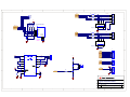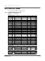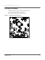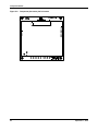
1
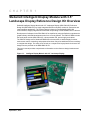
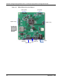
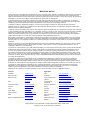
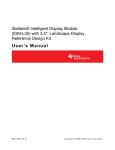
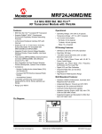
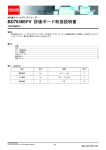
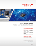
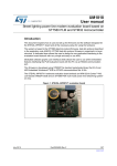
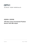
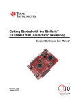
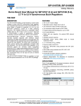
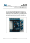
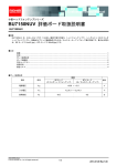
Stellaris® Intelligent Display Module with 3.5" Landscape Display Reference Design Kit User ’s Manual RDK-BDC-06 Co pyrigh t © 2 008– 201 0 Te xas In strumen ts Copyright Copyright © 2008–2010 Texas Instruments, Inc. All rights reserved. Stellaris and StellarisWare are registered trademarks of Texas Instruments. ARM and Thumb are registered trademarks, and Cortex is a trademark of ARM Limited. Other names and brands may be claimed as the property of others. Texas Instruments 108 Wild Basin, Suite 350 Austin, TX 78746 http://www.ti.com/stellaris 2 September 7, 2010 Stellaris® Intelligent Display Module with 3.5" Display Table of Contents Chapter 1: Stellaris® Intelligent Display Module with 3.5" Landscape Display Reference Design Kit Overview............................................................................................................................................................ 9 Kit Contents ...................................................................................................................................................... 10 Using the RDK .................................................................................................................................................. 10 Features............................................................................................................................................................ 10 Board Overview ................................................................................................................................................ 11 Chapter 2: Hardware Description .................................................................................................................. 13 Block Diagram .................................................................................................................................................. 13 Functional Description ...................................................................................................................................... 14 Microcontroller, Reset, and JTAG (Schematic page 1)................................................................................. 14 Microcontroller .......................................................................................................................................... 14 Debugging................................................................................................................................................. 14 LCD Panel and Voltage Regulators (Schematic page 2).............................................................................. 14 LCD Panel................................................................................................................................................. 14 Touch Panel .............................................................................................................................................. 15 High Power LED Driver ............................................................................................................................. 15 3.3 V DC Regulator ................................................................................................................................... 15 UART, microSD Card Slot, Speaker, Analog Inputs, Digital I/O (Schematic page 3) ................................... 15 RS232 Serial Port ..................................................................................................................................... 15 microSD Card Slot .................................................................................................................................... 15 Speaker..................................................................................................................................................... 15 Analog Inputs ............................................................................................................................................ 16 Digital I/O .................................................................................................................................................. 16 Serial Header ............................................................................................................................................ 16 Chapter 3: Software Development ................................................................................................................ 17 Software Description......................................................................................................................................... 17 Source Code..................................................................................................................................................... 17 Tool Options ..................................................................................................................................................... 17 Programming the IDM....................................................................................................................................... 18 Appendix A: Schematics................................................................................................................................ 21 Appendix B: Bill of Materials (BOM) ............................................................................................................. 25 Appendix C: Component Details ................................................................................................................... 27 September 7, 2010 3 4 September 7, 2010 Stellaris® Intelligent Display Module with 3.5" Display List of Figures Figure 1-1. Figure 1-2. Figure 2-1. Figure 2-2. Figure C-1. Figure C-2. Intelligent Display Module with 3.5" Landscape Display ................................................................. 9 IDM-L35 Board Overview Diagram ............................................................................................... 12 Intelligent Display Module with 3.5” Display Block Diagram.......................................................... 13 Debug Connection Pinout ............................................................................................................. 14 Component placement plot for top ................................................................................................ 27 Component placement plot for bottom .......................................................................................... 28 September 7, 2010 5 6 September 7, 2010 Stellaris® Intelligent Display Module with 3.5" Display List of Tables Table B-1. RDK-IDM-L35 Bill of Materials (BOM)........................................................................................... 25 September 7, 2010 7 8 September 7, 2010 C H A P T E R 1 Stellaris® Intelligent Display Module with 3.5" Landscape Display Reference Design Kit Overview Stellaris® Intelligent Display Module with 3.5" Landscape Display (MDL-IDM-L35) Reference Design Kit (RDK-IDM-L35) is a highly integrated QVGA touch-panel module for automation and instrumentation applications. The compact design is based on the Stellaris® LM3S1958 microcontroller; a highly integrated microcontroller incorporating a 32-bit ARM® Cortex™-M3 core. Development of software for the RDK-IDM-L35 is simplified by using the Stellaris comprehensive graphics library and ARM development tools from our tools partners. The IDM-L35 RDK includes the touch panel module (MDL-IDM-L35), a documentation CD, power supply, and cables. The IDM-L35 design uses a Stellaris® LM3S1958 microcontroller to handle display functions, touchscreen control, networking, and peripheral functions. Only a few additional ICs are necessary to complete the design. The entire circuit is built on a compact four-layer printed circuit board. All design files are provided on the RDK-IDM-L35 CD. This user's manual provides comprehensive information on the reference design hardware and software. Figure 1-1. September 7, 2010 Intelligent Display Module with 3.5" Landscape Display 9 Stellaris® Intelligent Display Module with 3.5" Landscape Display Reference Design Kit Overview Kit Contents The RDK-IDM-L35 reference design kit comes with the following: MDL-IDM-L35 Intelligent QVGA 3.5” Touch Panel USB to TTL Serial cable Debug adapter – Adapts 10-pin fine-pitch ARM JTAG connector to standard 20-pin connector Reference Design Kit CD – Complete documentation, including Quickstart and User's Guides – Graphical User Interface (GUI) installer – Complete source code, schematics, and PCB gerber files The source code can be modified and compiled using any of the following tools: Keil™ RealView® Microcontroller Development Kit (MDK-ARM) IAR Embedded Workbench Code Sourcery GCC development tools Code Red Technologies development tools Texas Instruments’ Code Composer Studio™ IDE Using the RDK The recommended steps for using the RDK are: Follow the Quickstart guide included in the kit. The Quickstart guide will help get the display module up and running in minutes. Use your preferred ARM tool-chain and the Stellaris Graphics library to develop a touch-panel application. Software applications are loaded into IDM flash memory using a JTAG/SWD debug interface or via the serial port using the included boot loader software. See Chapter 3, “Software Development,” for the programming procedure. The Stellaris Graphics Library Software Reference Manual and the Stellaris Peripheral Driver Library Software Reference Manual each contain specific information on software structure and function. Customize and integrate the hardware to suit an end application. This user's manual is an important reference for understand circuit operation and completing hardware modification. Features The RDK-IDM-L35 reference design kit provides the following features: Bright QVGA LCD touch-screen display – 262 K colors, 2.8" QVGA 320 x 240 pixels – White LED backlight with resistive touch panel Serial connectivity options – UART serial port with RS232 signal levels – UART serial port with TTL signal levels 10 September 7, 2010 Stellaris® Intelligent Display Module with 3.5" Display – Synchronous serial port High performance microcontroller and large memory – 32-bit ARM® Cortex™-M3 core – 256 KB Main Flash memory, 64 KB SRAM – microSD card slot Power – Board requires 5 V DC for operation, with an on-board regulator generating 3.3 V for the Stellaris MCU and other components. Three 5 V connector options are provided: • DC power jack J7 • Terminal block J1 • Serial header J8 Easy to customize – Includes full source code, example applications, and design files – Develop using tools supporting Keil™ RealView® Microcontroller Development Kit (MDK-ARM), IAR Embedded Workbench, Code Sourcery GCC development tools, Code Red Technologies development tools, or Texas Instruments’ Code Composer Studio™ IDE (using a Stellaris evaluation kit or preferred ARM Cortex-M3 debugger) – Supported by the Stellaris Graphics Library and Stellaris Peripheral Driver Library Board Overview Figure 1-2 shows an overview of the board. September 7, 2010 11 Stellaris® Intelligent Display Module with 3.5" Landscape Display Reference Design Kit Overview Figure 1-2. IDM-L35 Board Overview Diagram Serial Header JTAG/SWD Digital I /O (8) Digital I /O (4) microSD Card 1 Analog 5V Inputs (4) GND Digital I /O (4) RS232 Serial Port 12 5V GND September 7, 2010 C H A P T E R 2 Hardware Description The IDM-L35 design uses a Stellaris® LM3S1958 microcontroller to handle display functions, touch-screen control, UART, and peripheral functions. Only a few additional ICs are necessary to complete the design. The entire circuit is built on a compact four-layer printed circuit board. All design files are provided on the RDK-IDM-L35 CD. Block Diagram Figure 2-1 shows the IDM-L35 block diagram. Figure 2-1. Intelligent Display Module with 3.5” Display Block Diagram Analog ADC (4) Data QVGA 3.5" LCD Panel ESD Protected LCD Driver 5V Ctrl Stellaris LM3S1958 Microcontroller Analog touch signals Digital I/O (4) ESD Protected microSD card microSD Speaker RS232 Serial Digital I /O (4) Digital I /O (8) 5V DC Jack 3.3V Serial Header September 7, 2010 3.3V Regulator 5V 13 Hardware Description Functional Description This section describes the IDM-L35’s hardware design in detail. Microcontroller, Reset, and JTAG (Schematic page 1) Page 1 of the schematics details the microcontroller, and JTAG debug interface. Microcontroller At the core of the IDM-L35 is the Stellaris LM3S1958 microcontroller (U1). The Stellaris microcontroller operates at up to 50 MHz using an internal PLL. The LM3S1958 microcontroller has an internal LDO voltage regulator that supplies power for internal use. This rail requires only three capacitors for decoupling and is not connected to any other circuits. A reset switch (SW1) and R-C network (R25, C15) connect to the microcontroller’s RSTn input. An external reset circuit is not required by the LM3S1958 microcontroller, the R-C components simply serve to filter any noise on the reset line. Debugging The microcontroller supports JTAG and SWD debugging as well as SWO trace capabilities. To minimize board area, the IDM-L35 uses a 0.050” pitch header (J6) which matches ARM’s fine-pitch definition (Figure 2-2). Some in-circuit debuggers provide a matching connector. Other debuggers can be used with the ADA1 adaptor board included in the RDK. Figure 2-2. Debug Connection Pinout 1 2 TMS/ SWDIO TCK/ SWCLK TDO TDI SRSTn 3.3V GND GND n/c GND 9 10 LCD Panel and Voltage Regulators (Schematic page 2) Page 2 of the schematics contains the LCD panel connector, 3.3 V DC regulator, and the high voltage LED driver for the LCD panel backlight. LCD Panel The LCD panel is attached to FPC ZIF connector P1 and is a 3.5” TFT panel with an integrated controller (SSD2119). The graphics display memory resides in the LCD panel and contains 168 kilobytes. The LCD panel requires only a 3.3 V power supply which also simplifies system design. The LCD panel system interface has several modes of operation, for the IDM-L35 it is configured for 8080 series 16-bit parallel interface mode for improved data rate. Only two control lines (LCD_RDn, LCD_WRn) are required for reading and writing to the panel. A third signal (LCD_DC) selects between memory and display control register access. In order to meet reset signal timing requirements the microcontroller also controls the panel’s reset signal (LCD_RSTn). 14 September 7, 2010 Stellaris® Intelligent Display Module with 3.5" Display The LCD panel incorporates a white LED backlight with 6 LEDs in series which requires a high power serial driver (U7) for operation. The backlight power driver shutdown input is controlled by microcontroller GPIO pin PH0/CCP6. For full brightness, set PH0 high. For dim control, a 1 kHz PWM signal can be generated with CCP6. For additional LCD panel information, refer to the data sheet on the RDK-IDM-L35 CD and LCD driver source code in the Stellaris graphics library. Touch Panel Four ADC channels and four GPIO lines connect directly to the resistive touch panel, allowing the microcontroller to manage all aspects of operation. X and Y axis position measurements are made independently. For X-axis measurement, GPIO pins PC4 and PC5 are set HIGH and LOW respectively to form a resistor divider between 3 V and 0 V. The voltage on ADC4 and ADC5 indicates the X-axis position. To measure the Y-axis position, PD2 and PD3 are set HIGH and LOW respectively and the voltage on ADC6 or ADC7 is measured. Software controls calibration and finger press detection functions. High Power LED Driver The LCD panel backlight has 6 LEDs in series and requires a high power LED driver (U7) for operation, providing 20 mA at 20 V. The LCD_BL signal driven from a microcontroller GPIO is used to turn the backlight on and off. A 1 kHZ PWM signal can be used instead for dim control. 3.3 V DC Regulator The IDM-L35 operates with 5 V DC, which can be applied via DC jack J7, terminal block J1, or header J8. The RDK includes a USB to TTL serial cable that connects to J8 and receives 5 V from the USB port. DC regulator U3 generates 3.3 V for powering the board circuits and includes power indicator LED D1. UART, microSD Card Slot, Speaker, Analog Inputs, Digital I/O (Schematic page 3) The third schematic page contains the UART RS-232 transceiver, microSD card slot, speaker, terminal blocks, and headers. RS232 Serial Port The MAX3221 (U2) line transceiver interfaces between UART2 and the RS232 port pins on J3. UART2 uses ports PG0 and PG1. microSD Card Slot Standard microSD media may be used for image or data storage. The SD card is wired for use in SPI mode, rather than the 1-bit or 4-bit SD modes. Speaker Speaker SPK1 is a small magnetic audio transducer which is driven by PC7/CCP4 through a small transistor. CCP4 can be configured to generate a free-running tone at the required frequency. September 7, 2010 15 Hardware Description Analog Inputs Terminal block J1 provides four electrostatic discharge (ESD) protected analog inputs (T_ADC0-T_ADC3) connected to the corresponding ADC0-ADC3 channels of the microcontroller. Refer to the MDL-IDM-L35 data sheet for electrical limits for these inputs. Digital I/O Terminal block J2 provides four ESD-protected digital I/O signals connected to port A (PA2-PA5) of the microcontroller. These can be used to implement an SSI port or for I/O signals as required. Refer to the MDL-IDM-L35 data sheet for electrical specifications on these signals. Headers J4 and J5 provide 12 additional digital I/O lines directly connected to the microcontroller. Header J4 provides 8 digital I/O lines connected to port G (PG0-PG7) with PG0 and PG1 allocated for UART2, and header J5 provides 4 digital I/O lines connected to PA6, PA7, PD0, and PD1. Note that these signals do not have external ESD protection. Serial Header Header J8 is for use with the USB to TTL serial cable, and has connections to UART0 (PA0, PA1) and board power (5 V, GND). This provides a convenient way to power the board and provide a serial connection to update the board firmware. 16 September 7, 2010 C H A P T E R 3 Software Development This chapter provides general information on software development as well as instructions for Flash memory programming. Software Description The software provided with the IDM-L35 provides access to all of the peripheral devices supplied in the design. The Stellaris Peripheral Driver Library is used to operate the on-chip peripherals, the Stellaris Graphics Library is used to render graphical displays on the touch screen, and a set of board-specific drivers are provided to access the off-chip functionality on the IDM-L35. The Stellaris Graphics Library provides two levels of support for rendering graphical elements. In the lowest level, basic drawing primitives are provided, such as lines, circles, rectangles, and text rendering. Each primitive supports clipping to a single clipping rectangle, allowing only a portion of the display to be affected by the drawing primitives. Building upon the drawing primitives is a widget set, which combines the drawing of graphical elements with reactions to pointer events (in this case, presses on the touch screen). The widget set includes push buttons, check boxes, radio buttons, sliders, listboxes, and drawing canvases. By using the widget set, complex interactive graphical displays can be constructed quickly. A set of drivers for the on-board peripherals is also provided. This includes a driver for the touch screen, the audio transducer, the analog inputs, and the microSD card. The IDM-L35 is also supplied with a set of example applications that utilize the Stellaris Peripheral Driver Library and the Stellaris Graphics Library, along with the board-specific drivers for the on-board peripherals. These applications demonstrate the capabilities of the IDM-L35, and provide a starting point for the development of the final application for use on the IDM-L35. All example applications are integrated with the Stellaris boot loader to allow automatic firmware updates to be performed over the serial port using the LM Flash Programmer application. Source Code The complete source code for the IDM-L35 is included on the RDK-IDM-L35 CD. Refer to the Quickstart Guide for a detailed description of initial RDK hardware set up and how to install the source code. The source code and binary files are installed in the DriverLib tree. Tool Options The source code installation includes directories containing projects and/or makefiles for the following tool-chains: Keil™ RealView® Microcontroller Development Kit (MDK-ARM) IAR Embedded Workbench Code Sourcery GCC development tools Code Red Technologies development tools Texas Instruments’ Code Composer Studio™ IDE September 7, 2010 17 Software Development Evaluation versions of these tools can be downloaded from www.ti.com/stellaris. Note that, due to code size restrictions, the evaluation tools may not build all example programs for the IDM. A full license is necessary to re-build or debug all examples. Instructions on installing and using each of the evaluation tools can be found in the Quickstart guides (for example, Quickstart-Keil, Quickstart-IAR) which are available for download from the evaluation kit section of our web site at www.ti.com/stellaris. For detailed information on using the tools, refer to the documentation included in the tool chain installation or visit the website of the tools supplier. Programming the IDM The IDM-L35 software package includes pre-built binaries for each of the example applications. If you installed DriverLib to the default installation path of C:/DriverLib, you can find the example applications for the IDM in “C:/DriverLib/boards/rdk-idm-l35”. The Stellaris LM Flash Programmer is a free tool for programming Stellaris microcontrollers. It can be used in two modes to update the firmware on the IDM-L35. All IDM-L35 example applications are designed for use with the Stellaris boot loader which supports updating of the main application firmware via the serial port. Alternatively, the LM Flash Programmer utility can be used in conjunction with any Stellaris evaluation board to program the IDM-L35. The Stellaris evaluation board acts as a USB-to-JTAG/SWD hardware interface and should be used in cases where the boot loader image is not present or where the main application image is not behaving correctly and cannot transfer control to the boot loader. However, in normal operation, it is more convenient to program via the serial port. To program example applications into the IDM-L35 using the serial port for firmware update: 1. Install the LM Flash Programmer utility on a Windows PC. 2. Connect the 6-pin connector of the USB to TTL serial cable (FTDI part number TTL-232R-3V3) to header J8. Verify that J8 pin 1 (marked by the white triangle on PCB) is connected to the black wire of the 6-pin header. 3. Connect the USB connector of the serial cable to the PC. This provides power and connectivity to the serial port. 4. Run LM Flash Programmer. 5. In the Configuration tab, select “Manual Configuration - see below” in the “Quick Set” list. 6. Select “Serial (UART) Interface” in the list below “Interface” and set the COM port, set the baud rate to 115200, and click the “Disable Auto Baud Support” option. 7. Move to the Program tab and click the Browse button. Navigate to the example applications directory (the default location is “C:/DriverLib/boards/rdk-idm-l35/”). 8. Each example application has its own directory. Navigate into the example directory that you want to load and then go to the /gcc directory (or the directory corresponding to the tool chain you are using) which contains the binary (*.bin) files. Select the application binary file and click Open. Files that start with a “bl_” prefix are boot loader images and cannot be updated using this method. 9. Ensure that the “Program Address Offset:” is set to 0x800. If this is incorrect, the application will not boot correctly once the flash programming is completed. 10. Click the Program button to start the download process. 11. The program starts once the download is complete. 18 September 7, 2010 Stellaris® Intelligent Display Module with 3.5" Display To replace the boot loader image or to program example applications into the IDM-L35 using a Stellaris evaluation board to provide JTAG/SWD functionality: 1. Install LM Flash Programmer on a Windows PC. 2. Connect the 10-pin to 20-pin adapter (included in the RDK) to the evaluation board ribbon cable. This converts the standard 20-pin ARM header on the evaluation board to a fine pitch ARM header. 3. Carefully connect the socket of the adaptor board to J1 on the IDM. 4. Apply power to the IDM and connect the evaluation board (available separately) to a USB port. 5. Run LM Flash Programmer. 6. In the Configuration Tab use the Quick Set control to select the LM3S1968 Evaluation Board. These settings are compatible with the LM3S1958 implementation on the IDM-L35. 7. Move to the Program Tab and click the Browse button. Navigate to the example applications directory (the default location is “C:/DriverLib/boards/rdk-idm-l35/). 8. Each example application has its own directory. Navigate into the example directory that you wish to load and then into the /gcc directory (or the directory corresponding to the tool chain you are using) which contains the binary (*.bin) files. Files named with a "bl_" prefix are Stellaris boot loader images while those without the prefix are main application images. Select the binary file and click Open. 9. Set the "Erase Method" to "Erase Necessary Pages" and check the "Verify After Program" box. NOTE: Setting "Erase Entire Flash" when attempting to replace a main application image will erase the boot loader image and result in a hang when the IDM next boots. If this occurs, reflash a boot loader image using these instructions. 10. If flashing a boot loader image, set the "Program Address Offset:" value to 0x0000. If programming a main application image, set this value to 0x800. 11. Next, click on the Program button to start the Erase, Download, and Verify process. 12. Program execution will start once Verify is complete. The Debuggers in each of the tool-chains also include Flash programming capabilities, including support for high-performance in-circuit debug interfaces. September 7, 2010 19 Software Development 20 September 7, 2010 A P P E N D I X A Schematics This sections contains the schematic diagrams for the Intelligent Display Module. IDM-L35 Microcontroller and JTAG on page 22 IDM-L35 LCD Display and DC Regulators on page 23 IDM-L35 UART, microSD Card Slot, Speaker, Analog Inputs, and Digital I/O on page 24 September 7, 2010 21 Schematic page 1 1 2 3 4 5 6 3.3V TP3 TP4 TP5 TP6 A R11 10K 26 27 28 29 30 31 34 35 U0RX U0TX PA2 PA3 PA4 PA5 PA6 PA7 80 79 78 77 25 24 23 22 3.3V R12 R13 R14 R15 10K 10K 10K 10K TOUCH_XP TOUCH_XN LCD_RSTn SOUND B 72 73 74 75 6 5 2 1 SPI_CLK SPI_SEL_n SPI_RX SPI_TX ADC0 ADC1 ADC2 ADC3 19 18 17 16 41 40 37 36 PG0 PG1 PG2 PG3 PG4 PG5 PG6 PG7 OSC0 OSC1 48 49 3.3V 52 53 J6 1 3 5 7 9 C10 0.1uF C 2 4 6 8 10 TMS TCK TDO TDI 50 51 65 76 HDR 2X5-MH JTAG/SWD RST_n R25 10K SW1 2 4 Tactile Switch Y1 1 C15 0.1uF 2 8.000 MHz C24 18pF 64 9 15 21 33 39 45 54 57 63 69 82 87 94 3.3V 1 3 A U? C25 18pF 4 97 PA0/U0RX PA1/U0TX PA2/SSI0CLK PA3/SSI0FSS PA4/SSI0RX PA5/SSI0TX PA6/I2C1SCL PA7/I2C1SDA PC0/TCK/SWCLK PC1/TMS/SWDIO PC2/TDI PC3/TDO/SWO PC4 PC5 PC6/CCP3 PC7/CCP4 PE0/SSI1CLK PE1/SSI1FSS PE2/SSIRx PE3/SSI1Tx ADC3 ADC2 ADC1 ADC0 PG0/U2RX PG1/U2TX PG2 PG3 PG4 PG5 PG6 PG7 PB0/CCP0 PB1/CCP2 PB2/I2C0SCL PB3/I2C0SDA PB4 PB5/CCP5 PB6/CCP1 PB7/TRST PD0 PD1 PD2/U1RX PD3/U1TX ADC7 ADC6 ADC5 ADC4 PF0 PF1 PF2 PF3 PF4 PF5 PF6 PF7 PH0/CCP6 PH1/CCP7 PH2 PH3 66 67 70 71 92 91 90 89 LCD_D0 LCD_D1 LCD_D2 LCD_D3 LCD_D4 LCD_D5 LCD_D6 LCD_D7 10 11 12 13 95 96 99 100 47 61 60 59 58 46 43 42 PD0 PD1 TOUCH_YN TOUCH_YP TOUCH_XN TOUCH_XP LCD_D8 LCD_D9 LCD_D10 LCD_D11 LCD_D12 LCD_D13 LCD_D14 LCD_D15 B 86 85 84 83 LCD_D[15..0] LCD_D[15..0] 3.3V OSC0 OSC1 R22 R23 10K 10K XOSC0 XOSC1 LCD_BL LCD_WRn LCD_RDn LCD_DC WAKE HIB CMOD0 CMOD1 RST GND GND GND GND GND GND GND GND GND GND GND GND GND AGND AGND VDD33 VDD33 VDD33 VDD33 VDD33 VDD33 VDD33 VDD33 VBAT LDO CVDD CVDD CVDD CVDD AVDD AVDD C 8 20 32 44 56 68 81 93 3.3V TP7 3.3V TP8 55 7 14 38 62 88 C17 0.1uF C18 0.1uF C19 0.1uF C16 1uF C21 0.1uF C22 0.01uF C23 0.01uF C20 1uF Texas Instruments 3 98 108 Wild Basin Rd. Suite 350 Austin, TX 78746 This document contains information proprietary to Texas Instruments, Inc. and shall not be used for engineering design, procurement of manufacture in whole or in part without the express written permission of Texas Instruments, Inc. Copyright © 2006 Texas Instruments, Inc. All rights reserved. LM3S1958 Designer: D C26 0.1uF C27 0.1uF C29 0.1uF C30 0.1uF C31 0.1uF C32 0.01uF C28 1uF Drawing Title: Drawn by: Page Title: Stellaris Microcontroller, JTAG Arnaldo Cruz Approved: Size Date: 2 3 4 Document Number: B * 1 D Intelligent Display Module IDM-L35 Arnaldo Cruz 5 Rev 0001 10/13/2008 RB Sheet 1 6 of 3 Schematic page 2 1 2 3 4 5 6 3.3V VLED P1 M1 A LEDK LED_K LED_A XR YD XL YU TOUCH_XP TOUCH_YN TOUCH_XN TOUCH_YP LCD_D[15..0] LCD_D[15..0] LCD_RSTn LCD_WRn LCD_RDn LCD_DC C6 C7 C8 C9 0.01uF 0.01uF 0.01uF 0.01uF RESET CS SPICLK SPISDI 6 4 3 1 LCD_CSn LCD_RSTn U6 MMQA5V6T1G R16 10K 5 2 B R17 10K LD0 LD1 LD2 LD3 LD4 LD5 LCD_D0 LCD_D1 LCD_D2 LCD_D3 LCD_D4 LCD_D5 LCD_D6 LCD_D7 LD6 LD7 LD8 LD9 LD10 LD11 LCD_D8 LCD_D9 5V L1 BAT54 U7 5 4 LCD_BL C36 4.7uF 2 VIN SW SHDN FB D3 1 LCD_D10 LCD_D11 LCD_D12 LCD_D13 LCD_D14 LCD_D15 LD12 LD13 LD14 LD15 LD16 LD17 HSYNC VSYNC DCLK LEDK 3 GND R10 15.8 FAN5333B R21 10K C VLED D2 10uH AVDD C37 1uF TP1 J7 1 3 2 Power_Jack_2.5mm VCC DC RD WR PS0 PS1 PS2 PS3 WSYNC OE 5V 3.3V U3 4 R27 10K 1 2 C34 4.7uF VIN VOUT C14 4.7uF 5 VR GND CD C33 4.7uF 3 C12 0.1uF C13 0.1uF 1 2 3 4 5 6 7 8 9 10 11 12 13 14 15 16 17 18 19 20 21 22 23 24 25 26 27 28 29 30 31 32 33 34 35 36 37 38 39 40 41 42 43 44 45 46 47 48 49 50 51 52 53 54 55 56 57 58 59 60 A M1 B LCD_Panel_K3.5 C M2 R28 330 FPC_Socket_60pin PQ1N333MASPQ C35 0.47uF D1 GREEN_LED 3.3V Drawing Title: D D Intelligent Display Module IDM-L35 Page Title: LCD Display, DC Regulators Size Document Number: B Date: 1 2 3 4 5 Rev RB * 10/13/2008 Sheet 2 6 of 3 Schematic page 3 1 2 3 4 5 6 J1 ADC0 ADC1 ADC2 ADC3 TP9 TP10 TP11 TP12 R5 33.2 T_ADC0 1 R6 33.2 T_ADC1 2 R7 33.2 T_ADC2 3 R9 33.2 T_ADC3 4 A A R18 10K 6 4 J2 GND GND GND GND PA2 PA3 PA4 PA5 9 10 11 12 R1 33.2 T_PA2 1 R2 33.2 T_PA3 2 R3 33.2 T_PA4 3 R4 33.2 T_PA5 4 U4 B 5 1 MMQA5V6T1G 6 Term_Block_4P uSD Socket uSD Card 4 C11 0.1uF 5V 5 MMQA5V6T1G DAT2 CD/DAT3 CMD VDD CLK VSS DAT0 DAT1 2 P2 1 2 3 4 5 6 7 8 B 6 Term_Block_6P 3 R19 10K U5 microSD Card Slot 2 R20 10K SPI_CLK SPI_SEL_n SPI_RX SPI_TX 3 5 1 3.3V J4 U2 J3 PG1 PG0 11 9 C C1 0.47uF 2 C4 0.47uF 5 4 T1IN T1OUT R1OUT R1IN C1+ V+ C1- V- C2+ INVALID 3.3V 6 12 16 1 R8 10K 14 13 UTX 8 URX 1 2 3 5V HDR-1X8 HDR-1X3 UART 3 C2 0.47uF 7 C3 0.47uF 10 R24 33.2 R26 3.3V GND VCC J5 SOUND 2.80k 15 HDR-1X4 5V J8 6 5 4 3 2 1 U0TX U0RX Q1 MMBT3904 HDR-1X6 TTL-232R C5 0.47uF MAX3221 C 1 2 3 4 PA6 PA7 PD0 PD1 D4 1 SPK1 MMSD4148T1G 3 + 2 _ 4 Buzzer TP2 C2FORCEON FORCEOFF EN 1 2 3 4 5 6 7 8 PG0 PG1 PG2 PG3 PG4 PG5 PG6 PG7 Drawing Title: D D Intelligent Display Module IDM-L35 Page Title: UART, uSD Card Slot, Speaker, Analog inputs, Digital I/O Size Document Number: B Date: 1 2 3 4 5 Rev RB 0001 10/13/2008 Sheet 3 6 of 3 A P P E N D I X B Bill of Materials (BOM) Table B-1 provides the BOM for the RDK-IDM-L35. Table B-1. RDK-IDM-L35 Bill of Materials (BOM) TexasInstrumentsͲStellarisMicrocontrollers IDMͲL35BOM RevB7/29/2010 PartssolderedtoIDMͲL35PCB Designator Description Comment C1, C2, C3, C4, C5, C35 0.47uF C6, C7, C8, C9, C22, C23, C32 0.01uF MFG Footprint Ordering Quantity CAP, 0603, 0.47uF, 10%, 16V, X7R 1608[0603] Murata GRM188R71C474KA88D 6 CAP, 0402, 0.01uF, 10%, 25V, X7R 1005[0402] Murata GRM155R71E103KA01D 7 14 C10, C11, C12, C13, C15, C17, C18, C19, C21, C26, C27, C29, C30, C31 0.1uF CAP, 0402, 0.1uF, 10%, 16V, X7R 1005[0402] Murata GCM155R71C104KA55D C14, C33, C34, C36 4.7uF CAP, 0805, X7R, 4.7uF, 20%, 10V C0805 Murata GRM21BR61A475MA73L 4 C16, C20, C28 1uF CAP, 0805, X7R, 1uF, 10%, 10V C0805 Murata GRM21BR71A105KA01L 3 C24, C25 18pF CAP, 0402, C0G, 18pF, 50V 1005[0402] Murata GRM1555C1H180JZ01D 2 C37 1uF CAP, 1206, X7R, 1uF, 10%, 50V C1206 GRM31CR71H105KA61L 1 D1 GREEN_LED LED GREEN SGL 20mA 0805 D2012[0805] 7012X5 1 D2 BAT54 DIODE SCHOTTKY 200mA 30V SOT23A Murata CML Innovative Technologies Fairchild Semiconductor BAT54 1 D3 Zener_24V ZENER DIODE, 24V, 1W, SMA smb-85x108 Diodes Inc SMAZ24-13-F 1 D4 MMSD4148T1G DIODE Switching SOD-123 ON Semiconductor MMSD4148T1G J1 Term_Block_6P Terminal Block, 6 pin, 3.5mm, T/H CON6/3.5mm_ED555 On Shore Technology ED555/6DS J2 Term_Block_4P Terminal Block, 4 pin, 3.5mm, T/H CON4/3.5mm_ED555 On Shore Technology ED555/4DS 1 J3 HDR-1X3 HDR, 1x3, 0.025" PIN, 0.1" CTR HDR1X3 FCI 68000-103HLF 1 J4 HDR-1X8 HDR, 1x8 0.025" PIN, 0.1" CTR HDR1X8 FCI 68000-108HLF 1 J5 HDR-1X4 HDR, 1x4 0.025" PIN, 0.1" CTR HDR1X4 FCI 68000-104HLF 1 J6 HDR 2X5-MH MICRO HDR, 2X5, 0.050" CTR HDR2X5_SHRD_.050 HARWIN M50-3500542 1 J7 Power_Jack_2.5 Power Jack 2.5MM X 6.5MM J8 HDR-1X6 L1 P1 IND -- 10uH 0.9A, 0.133Ohms SMD FPC Socket 60 pin SMT 0.5mm pitch, Top, FPC_Socket_60 RA ZIF P2 uSD Socket HDR, 1x6 0.025" PIN, 0.1" CTR 10uH Q1 MMBT3904 R1, R2, R3, R4, R5, R6, R7, R9, R24 33 R8, R11, R12, R13, R14, R15, R16, R17, R18, R19, R20, R21, R22, R23, R25, R27 10K CONN micro SD card socket SMT 1 1 conn3-200120-pwrjk CUI Inc PJ-102B 1 HDR1X6 FCI 68000-106HLF 1 3225[1210] Taiyo Yuden 4UCON Technology Inc CBC3225T100MR 1 11792 1 1 CONN_FPC_60P_4UCONN_11792 CON8/MICROSD 3M 2908-05WB-MG General purpose NPN transistor SOT-23 ONSEMI MMBT3904LT1G 1 RES, SO, 0603, 33ohm, 1%, 1/10W J1-0603 Vishay/Dale CRCW060333R0FKEA 9 RES, SO, 0603, 10K, 1%, 1/10W J1-0603 Vishay/Dale CRCW060310K0FKEA 16 15.8 RES, SO, 0603, 15.8, 1%, 1/10W J1-0603 Vishay/Dale CRCW060315R8FKTA 1 R26 2.80k RES, SO, 0603, 2.80K, 1%, 1/10W J1-0603 Vishay/Dale CRCW06032K80FKEA 1 R28 J1-0603 Vishay/Dale CRCW0603330RFKEA 1 PIN2 CUI Inc CSS-73B16K 1 R10 330 RES, SO, 0603, 330 Ohm, 1%, 1/10W SPK1 Buzzer Magnetic Buzzer SW1 Tactile Switch C&K Components KMR221GLFS 1 U1 LM3S1958 SWITCH TACT SPST-NO 200GF GW SMD SW/KMR211G ARM Cortex-M3 Microcontroller without board-lock security feature Stellaris_PQFP100 Luminary Micro LM3S1958-IQC50* 1 U2 MAX3221 RS-232 Transceiver SSOP16 Texas Instruments MAX3221ECDB 1 U3 PQ1N333MASPQIC, 350mA LDO regulator SOT89-5 1 U4, U5, U6 SC-74/.95mm U7 MMQA5V6T1G Quad monolithic common anode TVS Serial LED Driver Switcher, 1.5MHz,30V,SMT FAN5333B Sharp Microelectronics PQ1N333MASPQ ON SEMICONDUCTOR MMQA5V6T1G SOT23-5 Fairchild FAN5333BSX 1 Y1 8.000 MHz Crystal_NX8045 NDK NX8045GB-8.000000MHZ 1 XTAL 8.000MHz 3 AdditionalPartsforModule Designator Comment LCD panel Tape Description LCD module 320 x 240 RGB, 3.5", 262K colors, touch panel Double sided foam tape, 0.125" thick, 2" x 1/2" cut piece Double sided foam tape, 0.125" thick, 1" x 3/4" cut piece MFG Footprint 3" x 2.5" Ordering Kentec ATP350G01 3M 4008-1/2"X36YD Quantity 1 2 1 AdditionalPartsforRDKAssembly Designator Comment Standoff Screws Description Standoff, aluminum, 4-40 thread, 0.187" OD, 1.0" long Machine screw 4-40 x 0.25" lead free machine screw Alternate supplier for screws above September 7, 2010 Footprint MFG Ordering Quantity Keystone 534-2031 4 Richco Plastic NSP-4-4-01 4 Building Fasteners NY PMS 440 0025 PH 25 Bill of Materials (BOM) 26 September 7, 2010 A P P E N D I X C Component Details This appendix contains details on component locations, including: Component placement plot for top (Figure C-1) Component placement plot for bottom (Figure C-2) Figure C-1. Component placement plot for top September 7, 2010 27 Component Details Figure C-2. Component placement plot for bottom 28 September 7, 2010 IMPORTANT NOTICE Texas Instruments Incorporated and its subsidiaries (TI) reserve the right to make corrections, modifications, enhancements, improvements, and other changes to its products and services at any time and to discontinue any product or service without notice. Customers should obtain the latest relevant information before placing orders and should verify that such information is current and complete. All products are sold subject to TI’s terms and conditions of sale supplied at the time of order acknowledgment. TI warrants performance of its hardware products to the specifications applicable at the time of sale in accordance with TI’s standard warranty. Testing and other quality control techniques are used to the extent TI deems necessary to support this warranty. Except where mandated by government requirements, testing of all parameters of each product is not necessarily performed. TI assumes no liability for applications assistance or customer product design. Customers are responsible for their products and applications using TI components. To minimize the risks associated with customer products and applications, customers should provide adequate design and operating safeguards. TI does not warrant or represent that any license, either express or implied, is granted under any TI patent right, copyright, mask work right, or other TI intellectual property right relating to any combination, machine, or process in which TI products or services are used. Information published by TI regarding third-party products or services does not constitute a license from TI to use such products or services or a warranty or endorsement thereof. Use of such information may require a license from a third party under the patents or other intellectual property of the third party, or a license from TI under the patents or other intellectual property of TI. Reproduction of TI information in TI data books or data sheets is permissible only if reproduction is without alteration and is accompanied by all associated warranties, conditions, limitations, and notices. Reproduction of this information with alteration is an unfair and deceptive business practice. TI is not responsible or liable for such altered documentation. Information of third parties may be subject to additional restrictions. Resale of TI products or services with statements different from or beyond the parameters stated by TI for that product or service voids all express and any implied warranties for the associated TI product or service and is an unfair and deceptive business practice. TI is not responsible or liable for any such statements. TI products are not authorized for use in safety-critical applications (such as life support) where a failure of the TI product would reasonably be expected to cause severe personal injury or death, unless officers of the parties have executed an agreement specifically governing such use. Buyers represent that they have all necessary expertise in the safety and regulatory ramifications of their applications, and acknowledge and agree that they are solely responsible for all legal, regulatory and safety-related requirements concerning their products and any use of TI products in such safety-critical applications, notwithstanding any applications-related information or support that may be provided by TI. Further, Buyers must fully indemnify TI and its representatives against any damages arising out of the use of TI products in such safety-critical applications. TI products are neither designed nor intended for use in military/aerospace applications or environments unless the TI products are specifically designated by TI as military-grade or "enhanced plastic." Only products designated by TI as military-grade meet military specifications. Buyers acknowledge and agree that any such use of TI products which TI has not designated as military-grade is solely at the Buyer's risk, and that they are solely responsible for compliance with all legal and regulatory requirements in connection with such use. TI products are neither designed nor intended for use in automotive applications or environments unless the specific TI products are designated by TI as compliant with ISO/TS 16949 requirements. Buyers acknowledge and agree that, if they use any non-designated products in automotive applications, TI will not be responsible for any failure to meet such requirements. Following are URLs where you can obtain information on other Texas Instruments products and application solutions: Products Applications Amplifiers amplifier.ti.com Audio www.ti.com/audio Data Converters dataconverter.ti.com Automotive www.ti.com/automotive DLP® Products www.dlp.com Communications and Telecom www.ti.com/communications DSP dsp.ti.com Computers and Peripherals www.ti.com/computers Clocks and Timers www.ti.com/clocks Consumer Electronics www.ti.com/consumer-apps Interface interface.ti.com Energy www.ti.com/energy Logic logic.ti.com Industrial www.ti.com/industrial Power Mgmt power.ti.com Medical www.ti.com/medical Microcontrollers microcontroller.ti.com Security www.ti.com/security RFID www.ti-rfid.com Space, Avionics & Defense www.ti.com/space-avionics-defense RF/IF and ZigBee® Solutions www.ti.com/lprf Video and Imaging www.ti.com/video Wireless www.ti.com/wireless-apps Mailing Address: Texas Instruments, Post Office Box 655303, Dallas, Texas 75265 Copyright © 2010, Texas Instruments Incorporated