1
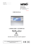
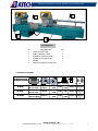
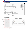
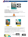
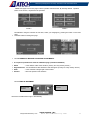
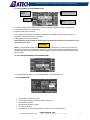
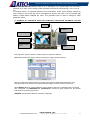
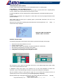
Machinery & Equipment for Vinyl & Aluminum & Steel Fabrication
USER’S MANUAL
ZIGMA-02 SA / ZIGMA-02 A / ZIGMA-02 AP
(DC 420 M / DC 420 P / DC 420 PB)
ATECH MACHINE, INC.
[email protected]
www.ATechMachinery.com
Machinery & Equipment for Vinyl & Aluminum & Steel Fabrication
CONTENTS
1. General Information
1.1. Introduction
1.2. Distributor
2. Machine’s Description and Purpose of Use
2.1. Machine’s description
2.2. Technical features
2.3. Overall dimensions
2.4. Cutting diagram
2.5. Part lists and technical drawings
3. Safety
3.1. Safety information
3.2. Accident prevention
3.3. General safety information
4. Transport of the Machine
5. Installation of the Machine
5.1. Preparation
5.2. Electric connection
5.3 Air pressure adjustments
6. Machine Safety Information
7. Operation
7.1. General working information
7.2. Dimensional and angular adjustments
7.3. Cutting speed adjustment
7.4. Cutting operation
7.4.1. ZIGMA-02 SA (DC 420 M) Double head 90° cutting
7.4.2. ZIGMA-02 SA (DC 420 M) Double head angular cutting
7.5. ZIGMA-02 A (DC 420 P) Double head miter saw
7.5.2. ZIGMA-02 A (DC 420 P) Double head cutting screen information
7.6. ZIGMA-02 AP (DC 420 PB) information
8. Safe Installation of the Saw Blade
9. Maintenance
9.1. Periodic checks
9.2. Maintenance at the end of working day
10. Troubleshooting Guide
[email protected]
ATECH MACHINE, INC.
www.ATechMachinery.com
1
Machinery & Equipment for Vinyl & Aluminum & Steel Fabrication
WARRANTY CONDITIONS
1.The warranty period is 2 years from the delivery date of the machine.
2.All parts of the machine are under the warranty of our company.
3.If the machine has a defect within the warranty period, the warranty period is extended by the repair
period. The repair period of the machine is max. 30 working days. This period begins with the date of
notofication of the defect to the service station, or if there is no service station, to the authorized dealer,
representative, agent, importer or manufacturer. If the defect cannot be repaired within 15 working days, the
manufacturer or importer has to deliver the customer another machine with similar features until the repair
has been completed.
4.If the machine has a defect due to material, workmanship and assembly fault, the repair will be carried out
without any charge for parts, labor or any other charges.
5. The customer can request the replacement of the machine, or the return of the purchase price or
discount in proportion with the fault if;
- the same defect occurs more than twice within the stipulated warranty period after the delivery, or in case
of more than four different defects within the stipulated warranty period., or if the total defects of different
defects exceeds six defects, and makes the machine unusable,
-the repair period for the machine is extended,
- it is determined with a report of the service station, or in case that there is no service station, by the dealer,
representative, agent, importer or manufacturer, that a repair of the machine is not possible,
6.Defects due to use of the machine in contrary with the features described in the machine’s user’s manual
are excluded from the warranty.
[email protected]
ATECH MACHINE, INC.
www.ATechMachinery.com
2
Machinery & Equipment for Vinyl & Aluminum & Steel Fabrication
1. GENERAL INFORMATION
1.1. INTRODUCTION
The user’s manual given by the manufacturer contains necessary information about the machine parts.
Each machine operator should read these instructions carefully, and the machine should be operated after
fully understanding them.
Safe and efficient use of the machine for long term depends on understanding and following the instructions
contained in this manual. The technical drawings and details contained in this manual constitute a guide for
the operator.
1.2. DISTRIBUTOR
ATech Machine, Inc.
309 Ridgemont Ave. – Rockville, MD 20850
Phone: +1-301-595-1816 Fax: +1-301-560-6627
Website: www.ATechMachinery.com E-mail: [email protected]
In case of any technical problem please contact your nearest ATECH dealer, or ATECH head office
through the above mentioned phone, fax or e-mail address.
Technical labels with the model description of the machine are fixed onto the front side of each
machine.
The machine’s serial number and manufacturing year are stipulated on the technical label.
Average life of the machine is 10 years. If you have any further failure and complaint, please inform
our head office as above or your dealer.
2. MACHINE’S DESCRIPTION and PURPOSE OF USE
2.1 MACHINE’S DESCRIPTION
Double head miter saw with 16.5” (420 mm) circular saw blades designed for double head, single head and
straight or angular cutting of PVC and Aluminum profiles.
The left cutting head is fixed, while the right head is movable. Cutting at 90º and 45º angles the saw heads
are tilted automatically. At 15º-22.5º-30º and other intermediate angles the saw heads are adjusted
manually.
The saw blade movement is hydro-pneumatically, and it is possible to adjust the movement speed of the
saw blade precisely according to the material to be cut.
The number of pieces to be cut can be entered and programmed via data input on the keypad located on
the machine.
The machine is equipped with pneumatic clamps operated via low pressure, and has been designed so that
both hands are occupied during the cutting operation for maximum operator’s safety.
The movable right saw head is equipped with a pneumatic brake, which is activated automatically when
starting the cutting operation to fix the movable head.
The machine disposes about a conveyor system connected onto the movable right head.
Both cutting heads are fully guarded for maximum operator’s safety.
The cutting measurement can be adjusted precisely via digital read-out system.
The machine has been designed according to the European CE and the UL & CSA Safety Directives.
Standard Equipment
2 x 16.5” (420 mm) carbide tipped saw blades
Air gun
Additional conveyor on the movable unit
User's Manual
1
[email protected]
Optional Equipment
Spray mist lubrication
4
ATECH MACHINE, INC.
www.ATechMachinery.com
3
Machinery & Equipment for Vinyl & Aluminum & Steel Fabrication
6
3
2
5
ILLUSTRATION 1
No
1
2
3
4
5
6
DESCRIPTION
QTY
FIXED CUTTING UNIT
FIXED CONTROL PANEL
MOVABLE CONTROL PANEL
MOVABLE CUTTING HEAD
FRAME
PROFILE SUPPORT CONVEYOR
1
1
1
1
1
1
2.2 TECHNICAL FEATURES
H
TEKNİK ÖZELLİKLER
TECHNICAL FEATURES
d
BAR
Hava Tük
Air Const
L
D
W
cm
Kg
DC 420 M
2.2 kWx2 50 Hz
400 V AC 3 N PE
d= 30 / 32 mm 3000 dev/dak
45 Lt/dak
6-8 Bar
116x501x170 1030 1290
D=420 mm .
Lt/Min
RPM
DC 420 P
2.2 kWx2 50 Hz
400 V AC 3 N PE
d= 30 / 32 mm 3000 dev/dak
45 Lt/dak
6-8 Bar
116x501x170 1056 1316
D=420 mm .
Lt/Min
RPM
DC 420 PB
2.2 kWx2 50 Hz
400 V AC 3 N PE
[email protected]
d= 30 / 32 mm 3000 dev/dak
45 Lt/dak 116x501x170
1086 1346
6-8 Bar
D=420 mm .
RPM
Lt/Min
ATECH MACHINE, INC.
www.ATechMachinery.com
4
Machinery & Equipment for Vinyl & Aluminum & Steel Fabrication
1468
330
1730
2.3. OVERALL DIMENSIONS
420
700
2560
700
870
420
180
1095
4980
790
1320
6390
FIGURE 1
2.4. CUTTING DIAGRAM
90° DERECEDE
Min. 200 mm
Max. 4160 mm
45° DERECEDE
Min. 430 mm
Max. 4160 mm
FIGURE 2
[email protected]
ATECH MACHINE, INC.
www.ATechMachinery.com
5
Machinery & Equipment for Vinyl & Aluminum & Steel Fabrication
2.5. PART LISTS and TECHNICAL DRAWINGS
2
2
1
No
STOCK No
1
1PN020000-0045
2
2TU011110-0533
PART NAME
63x100 PISTON (WITH MIDDLE ANKLE
CONNECTION)
90° FIXING ADJUSTMENT PART
QTY
2
4
FIGURE 3
8
FIGURE 4
[email protected]
ATECH MACHINE, INC.
www.ATechMachinery.com
6
Machinery & Equipment for Vinyl & Aluminum & Steel Fabrication
ZIGMA-02 A PART LIST
QTY
No
2
1
1
2
67
9
111-193 Front cover
112-115 Front plate-M
112-143 Front plate-F
142-042 Saw blade shaft
12
112-156 Upper profile piston connection
2
15
141-429 Lever
2
76
17
211-044 Motor rear protection cover
112-118 Rear plate (right)
112-119 Rear plate (left)
162-106 XCKJ 167 Limit switch
2
1
1
2
No
4
8
20
22
PART NAME
77
2
82
191-006 30x62x16 6206 Bearing
4
84
111-226 Pulley protection
2
85
150-035 Magnifier connection
1
110
111-266 Travel bed
2
112
150-042 Angle reader
2
128
211-044-2 Chip manifold
2
130
242-008 Piston fork
2
132
163-002 2.2 kW motor
2
2
137
142-042 Bearing bracket
2
1
1
1
143
150-041 Travel bed connection
111-261 Arm bearing (right)
111-260 Arm bearing (left)
141-425 Bearing shaft
2
1
1
2
550-001 Hydro pull cylinder group
2
36
211-044-1 Upper protection cover
2
38
201-005 420 mm (17”) Saw blade
2
46
2
1
1
64
145-081 Cover piston ankle bracket
112-129 Table (right)
112-130 Table (left)
112-113 Angular set square (right)
112-114 Angular set square (left)
111-262 Head (right)
111-191 Head (left)
146-024 Brake piston tube
65
112-158 Digital read-out (manual)
1
57
59
QTY
232-023 Brake valve label
(manual)
142-051 Flywheel intermediate
adapter (manual)
112-146 Movable set square (right)
112-117 Movable set square (left)
222-056 Sensor connection
housing
242-040 50x30 PAG cylinder
32
52
PART NAME
69
72
146
157
1
1
1
1
1
3. SAFETY
3.1. SAFETY INFORMATION
The symbols shown hereunder are necessary to be read with special attention. Not reading or
observing of them may cause damage to the equipment or personal injury.
IMPORTANT
The IMPORTANT symbol above is one telling to apply special care and to be careful at carrying out
the specified operation.
CAUTION !
The CAUTION! Symbol above warns you against specific dangers, and requires to read the text. Not
observing may cause damage to the equipment.
DANGER WARNING
The above symbol DANGER WARNING, warns you against specific dangers, and you have
definitely to read them. Negligence may cause damage to the equipment and bodily injury.
Read the user’s manual carefully before using the machine or carrying out maintenance works.
[email protected]
ATECH MACHINE, INC.
www.ATechMachinery.com
7
Machinery & Equipment for Vinyl & Aluminum & Steel Fabrication
3.2. ACCIDENT PREVENTION
3.2.1. Our machines are manufactured in accordance with EN 60204-1 and EN 292-2 CE, and UL & CSA
safety directives, which cover national and international safety directives.
3.2.2. It is the task of the employer to warn his staff against accident risks, to train them on prevention of
accidents, to provide for necessary safety equipment and devices for the operator’s safety.
3.2.3. Before starting to work with the machine, the operator should check the features of the machine,
learn all details of the machine's operation.
3.2.4. Machine should be operated only by staff members, who have read and understood the contents of
this manual.
3.2.5. All directives, recommendations and general safety rules contained in this manual have to be
observed fully. The machine cannot be operated in any way for purposes other than those described herein.
Otherwise, the manufacturer shall not be deemed responsible for any damages or injuries. And such
circumstances would lead to the termination of the warranty.
3.3. GENERAL SAFETY INFORMATION
3.3.1. The power cable should be led in such a way that nobody can step on it or nothing can be
placed on it. Special care has to be taken regarding the inlet and outlet sockets.
3.3.2. If the power cable should be damaged during operation, don't touch and unplug it. Never use
damaged power cables.
3.3.3. Don’t overload machines for drilling and cutting. Your machine will operate more safely with
power supply in accordance with the stipulated values.
3.3.4. Don’t place your hands between parts in motion.
3.3.5. Use protective eye glasses and ear plugs. Don't wear oversize clothes and jewels. These can
be caught by moving parts.
3.3.6. Keep your working place always clean, dry and tidy for accident prevention and safe operation.
3.3.7. Use correct illumination for the safety of the operator. (ISO 8995-89 The Lighting of
Indoor Work Systems)
3.3.8. Don't leave anything on the machine.
3.3.9. Don’t use any materials other than those recommended by the manufacturer for cutting
operations on the machine.
3.3.10. Ensure that the work piece is clamped appropriately by the machine's clamp or vice
3.3.11. Ensure safe working position, always keep your balance.
[email protected]
ATECH MACHINE, INC.
www.ATechMachinery.com
8
Machinery & Equipment for Vinyl & Aluminum & Steel Fabrication
3.3.12. Keep your machine always clean for safe operation. Follow the instructions at maintenance
and replacement of accessories. Check the plug and cable regularly. If damaged, let it replace by a
qualified electrician. Keep handles and grips free of any oil and grease.
3.3.13. Unplug first, before conducting and maintenance works.
3.3.14. Ensure that any keys or adjustment tools have been removed before operating the machine.
3.3.15. If you are required to operate the machine outside, use only appropriate extension cables.
3.3.16. Repairs should be carried out by qualified technicians only. Otherwise, accidents may occur.
3.3.17. Before starting a new operation, check the appropriate function of protective devices and
tools, ensure that they work properly. All conditions have to be fulfilled in order to ensure proper
operation of your machine. Damaged protective parts and equipment have to be replaced or repaired
properly (by the manufacturer or dealer).
3.3.18. Don’t use machines with improper functioning buttons and switches.
3.3.19. Don’t keep flammable, combustive liquids and materials next to the machine and electric
connections.
IMPORTANT
4. TRANSPORT OF THE MACHINE
* The transport should be done by qualified personnel only.
4.1. The machine should be transported by lifting with proper equipment (not touching the ground during the
transport). Advised transportation type is presented below.
4.2. The machine is delivered wrapped with nylon, unless other packaging method has been agreed upon
with the customer.
4.3. For the weight and dimensions of the machine see Technical Features on Page 31.
4 Pieces, 1500 mm long
ADVISED TRANSPORTATION TYPE
5. INSTALLATION OF THE MACHINE
The machine should be located so that at least 150 cm (60”) space remains between it and the rear wall.
On the back side of the machine you will find connection tube for the collection of burr and swarf, hydropneumatic system, cable channels, power supply connection plug and the ENCODER counter of the digital
read-out.
The machine should be placed on even ground able to bear the weight of the machine. For the weight of the
machine see Technical Features on Page 4.
Space in accordance with the profile length to be cut should be left on both sides of the machine. The
recommended distance for each side is 300 cm (120”).
[email protected]
ATECH MACHINE, INC.
www.ATechMachinery.com
9
Machinery & Equipment for Vinyl & Aluminum & Steel Fabrication
The machine should be placed on even, hard ground capable to bear the weight of the machine (for the
machine weight see page 4).
Conveyor
3000 mm
Min 1500 mm
Min 3000 mm
Min 3000 mm
FIGURE 5
Conveyor shaft
adjustment bolt
IMPORTANT
5.1. PREPARATION
5.1.1. Dismantle the transport safety connection parts before operating the machine (see Illustration 5). Do
not carry out the electric and pneumatic connections before dismantling the transport safety connection
parts.
5.1.2. Keep the dismantled transport safety connection parts for future transportation purposes.
5.1.3. To avoid any damage the front control panel should be dispatched dismantled. Put the front control
panel in place as shon in Illustration 2.
5.1.3. Also the profile feeding conveyor and swarf absorbing manifold (used at the right and left cutting
units) are dispatched dismantled. Assemble them as shown in Illustrations 3 and 3-1.
5.1.4. Check that the shafts on the frame of the profile support conveyor (see Figure 5) are parallel, if not,
ensure that these shafts are parallel.
M10x125
Hex. Screw
Conveyor
ILLUSTRATION 2
Connection
Shaft
Conveyor Connection
Sheet
ILLUSTRATION 3
[email protected]
ATECH MACHINE, INC.
www.ATechMachinery.com
10
Machinery & Equipment for Vinyl & Aluminum & Steel Fabrication
Conveyor shaft
bold
Conveyor
Shaft
M10x30 Hez.
Screw
Conveyor shaft
support sheet
ILLUSTRATION 3-1
Assemblying the chip removal manifold.
Chip removal
manifold
M6x12 allen
screw 2 item
M6x12 allen
screw 2 item
ILLUSTRATION 4
Connection to ZIGMA-02 SA / A Power Supply
5.2. ELECTRIC CONNECTION
5.2.1 Use only power cables in accordance with the CE Standards, cables of H07RNF type.
5.2.2 Check the power supply before switching the machine on. (see Page 12, Item 6.2)
5.2.3 Connect the machine according to the wiring diagram.
Transport
safety -2
FIGURE 4
CAUTION !
Transport
safety -2
ILLUSTRATION 5
* The electric connections have to be carried by qualified electricians only. Check the direction of
the saw blade rotation. If the saw blade rotates in reverse direction, check the cable connections
and re-connect if necessary.
**A saw blade rotating in reverse direction causes danger both for the operator and the equipment.
The teeth of the saw blade would be damaged and even broken.
[email protected]
ATECH MACHINE, INC.
www.ATechMachinery.com
11
Machinery & Equipment for Vinyl & Aluminum & Steel Fabrication
5.2.3 In order to ensure correct direction of the saw blade rotation, connect the machine to the power
supply and follow the instructions below.
a- Press the Start button.
b- Activate the clamps. Observe the direction of the saw blade rotation from the
open side of the guard.
Note: If the clamps are not activated the saw blades will rotate, however, they will not move due to
operator safety.
c- The correct direction of the saw blade rotation is shown in Figure 4.
If the direction of saw blade rotation is wrong;
The electric socket connections have to be checked by a qualified electrician and
corrected accordingly.
Don’t use the machine before ensuring the correct direction of the saw blade rotation.
5.3 AIR PRESSURE ADJUSTMENT
For proper working of the pneumatic system the air pressure has to be between 7-8 Bar. Don’t operate the
machine at an air pressure below 6 Bar. Read the manometer to check and adjust the air pressure. See
Figure 6.
Follow the instructions below for air pressure adjustments.
5.3.1 Pull the adjustment button of the conditioner upwards.
5.3.2 Turning the adjustment button in clockwise direction increases the pressure. Turning the adjustment
button in counter clockwise direction decreases the pressure.
5.3.3 Once you read 7-8 Bar on the manometer, push the adjustment button of the conditioner down and
lock it in that position.
5.3.4 The conditioner unit collects the water within the air system in a receptacle in order to prevent damage
to the pneumatic system components. Discharge this water periodically (at the end of the working day) by
pressing or opening the button under the conditioner.
5.3.5 The manufacturer recommends to use the following oils with the conditioner: TELLLUS C 10 / BP
ENERGOL HLP 10/ MOBIL DTE LIGHT / PETROL OFISI SPINDURA 10.
Pressure Adjustment
Button
Air Pressure and
Water Discharge
Screw
FIGURE 6
Manometer
Oil Depot
Oil Filling Cap
6. MACHINE SAFETY INFORKATION
6.1 It is not allowed to operate the machine with the blade guards and other safety equipment removed.
6.2 Your machine operates at a voltage of 440V ~ 3-Phase 60 Hz (400V 50Hz). Let the electric installation
of the machine carry out by a qualified electrician.
6.3 Lifting, installation, electric and pneumatic maintenance works of the machine should be carried out by
qualified personnel only.
6.4 Routine maintenance works and scheduled maintenance should be carried out only after disconnecting
the power and pneumatic supply by qualified personnel.
6.5 Ensure that the machine has been cleaned, tested and maintained before starting to work.
6.6 Check the safety devices, power cable and moving parts periodically. Replace damaged safety
equipment and parts.
[email protected]
ATECH MACHINE, INC.
www.ATechMachinery.com
12
Machinery & Equipment for Vinyl & Aluminum & Steel Fabrication
6.7 Don’t replace the saw blade before disconnecting the power supply to the machine.
6.8 Don’t keep foreign materials in the working area ruing operation of the machine. Keep your hands away
from moving parts
IMPORTANT
The safety information has been given above. Please read the instructions carefully and keep this
manual at an easy accessible place for reference.
7. OPERATION
7.1. GENERAL WORKING INFORMATION
7.1.1 Our double head miter saws ZIGMA-02 SA and ZIGMA-02 A are for the cutting of non-ferrous metals
like aluminum, wood and PVC materials. The operator adjusts the cutting speed of the saw blade according
to the material to be cut (manually). The carbide tipped saw blade equipped with these machines ensure
high quality clean cuts of the material. The measurement system on the machine and the digital display
enables you adjust the cutting length precisely.
The cutting length of materials to be cut at ZIGMA-02 SA semi-automatic double head miter saw
is adjusted precisely using the measuring tape on the machine and the digital read-out attached to
it. See Illustration 3.
At the ZIGMA-02 A fully automatic double head miter saw: applications like moving, positioning at the
cutting point, braking, cutting and tilting of both cutting heads to 90 and 45 degree angles are carried out
automatically via electronic positioning. See Ilustration 7.
It is possible to move the movable cutting head to the cutting start manually by using the buttons on the
control panel (at ZIGMA-02 A).
7.2 DIMENSIONAL AND ANGULAR ADJUSTMENTS
After completion of the electric and pneumatic connections of the double head saw ZIGMA, the
appropriateness of the cutting length and angle depends on;
a) Proper length adjustment and
b) Angle adjustment.
7.2.1 ZIGMA-02 SA Double Head Miter Saw
a-) Distance adjustment at 90º cutting
7.2.1.1 Deactivate the brake by turning the brake button on the movable cutting head.
7.2.1.2 Move the movable cutting head via the hand wheel to the cutting start point using the measuring
tape on the machine frame and the magnifier (see Illustration 3).
7.2.1.3 Make the precise and final (+ / - 0.1) length adjustment by turning the hand wheel to the right or left.
7.2.1.4 Fix the movable head by activating the pneumatic braking system (see Illustration 3).
Angle value distance
positioning arm
Head Fixing
Arm
Display (Digital
Read-Out)
Brake Activation
Button
Hand
Wheel
Hand Wheel
Illustration 3
ZIGMA-02 SA
NOTE: FOR THE OPERATOR’S SAFETY, THE CLAMPS WILL NOT WORK AND THE CUTTING HEAD
WILL NOT MOVE BEFORE THE BRAKING SYSTEM ON THE MOVABLE HEAD HAS BEEN ACTIVATED.
Angle Reader
[email protected]
ATECH MACHINE, INC.
www.ATechMachinery.com
13
Machinery & Equipment for Vinyl & Aluminum & Steel Fabrication
Measuring
Tape
Magnifier
Illustration 4
b-) At Angular Cutting
To make angular cuttings at 15º-22.5º-30º-45º on both cutting heads;
7.2.1.5. Losen the head fixing arm (see Illustration 3).
7.2.1.6. Position the cutting head at the desired angle manually by using the angle value distance
positioning arm (see Illustration 3).
7.2.1.7.After reading the desired angle on the angle reader (see Illustration 4) and confirming the correct
angle adjustment, fix the angle adjustment by tightening the head fixing arm.
NOTE: ENSURE THAT THE PNEUMATIC CLAMPS ARE OUTSIDE THE CUTTING RANGE OF THE
SAW BLADE AFTER ADJUSTING THE DESIRED ANGLE.
X
WRONG
CORRECT
7.3 CUTTING SPEED ADJUSTMENT
7.3.1 The saw blade cutting speed adjustment and simultaneous operating of both cutting heads at the
double head miter saw is important for preventing loss of time and to ensure high-quality clean cuts.
7.3.2 The two saw blade groups can be adjusted independently from each other through the reducer valves
located on the hydro-pneumatic system at both cutting heads. See Illustration 5)
7.3.3 If the cutting speed is too high, turn the cutting speed adjustment screw (see Illustration 5) in
clockwise direction until the desired speed has been reached. If the speed is too low, turn the adjustment
screw in reverse direction.
Ensure simultaneous operation of both saw blades.
Emergency
Stop Button
[email protected]
ATECH MACHINE, INC.
www.ATechMachinery.com
Motor Start /
Stop (Right)
14
Machinery & Equipment for Vinyl & Aluminum & Steel Fabrication
Motor Start /
Stop (Left)
Cutting start
with both
hands (left)
Cutting Start
with both
hands (right)
Clamp
switch
Illustration 5
Illustration 6
7.4 CUTTING OPERATION
7.4.1 Cutting at 90° at ZIGMA-02 SA Double Head Miter Saw: After adjusting the cutting speed according
to the material to be cut as described under 7.3;
7.4.1.1 Turning the hand wheel, move the movable head to the cutting start point by reading the
measurement on the display. After adjusting the cutting length, fix the movable head by activating the brake
on the movable head (by turning the ON/OFF brake switch).
7.4.1.2 Push the profile or material to be cut from the direction of the movable head to the direction of the
fixed head. Fix the profile by using the clamp switch (see Illustration 6).
7.4.1.3 Operate the saw blades by pressing the Motor Start 1 and 2 buttons on the control panel (see
Illustration 6).
7.4.1.4 Keep the the cutting buttons pressed simultaneously until the work piece is cut off.
7.4.1.5 Release the buttons after the cutting operation is finished. Both saw blades return to their start
position.
7.4.1.6 Release the clamps and remove the cut work pice.
CAUTION !
In case of emergency or danger release the cutting buttons or press the emergency stop button.
After pressing the Motor Stop button, the saw blades terminate their free rotation within 15 secs.
and stop completely.
7.4.2 Angular Cutting at ZIGMA-02 SA Double Head Miter Saw:
7.4.2.1 Loosen the head fixing arm by turning it (Illustration 3). Turn the head by using the angle value
distance positioning arm on the head to position the head at the desired angle. Adjust the desired angle by
reading the angle degree from the digital read-out (see Illustration 3).
7.4.2.2 Fix the adjusted angle by tightening the head fixing arm.
7.4.2.3 Apply the same procedures as under 7.4.1 for the other procedures.
NOTE: ENSURE THAT THE HEAD FIXING ARM OF THE ZIGMA-02 SA DOUBLE HEAD MITER
SAW SHOWN IN ILLUSTRATION 3 IS TIGHTENED PROPERLY AFTER THE ANGLE
ADJUSTMENT.
[email protected]
ATECH MACHINE, INC.
www.ATechMachinery.com
15
Machinery & Equipment for Vinyl & Aluminum & Steel Fabrication
7.5 ZIGMA-02 A AUTOMATIC DOUBLE HEAD MITER SAW
7.5.1 Distance adjustment at 90° and angular cutting:
7.5.1.1 Enter the cutting length value of the material to be cut, the cutting angle (90° ve 45°), the cutting
quantity by pressing the electronic positioning buttons located on the control panel (for details see
Operation 7.5.2).
Emergency stop
button
Right cutting unit
Start / Stop button
Left Cutting unit
Start / Stop button
Clamping
button
Send measuring
button
Electronic
Control system
Illustration 7
ZIGMA-02 A
7.5.2
SAFE USAGE OF POSITIONING DEVİCE AT ZIGMA-02 A AUTOMATIC DOUBLE HEAD
SAW MACHINE;
7..5.2.1 Electronical positioning equipment is touch screen
7.5.2.2 Switch the Main Switch to ON Pass the introduction page on the monitor by pressing anywhere on
the screen
.
7.5.2.3 On the second display page pres reference button, whereafter the movable cutting head moves to
the reference point.
PAGE 1
[email protected]
PAGE 2
ATECH MACHINE, INC.
www.ATechMachinery.com
16
Machinery & Equipment for Vinyl & Aluminum & Steel Fabrication
7.5.2.4 Third page is the screen page of which operation selections exist. By touching desired operation
button on the screen, it is passed to the operation
.
PAGE 3
PAGE 4
•
7.5.2.5 When using the machine the first time, select your language by pressing the button on the third
page.
Use back button for exiting from page.
•
7.5.2.6. ZIGMA-02 A MACHINE CALIBATION ADJUSTMENTS:
• It is required a password to reach the calibration page. (Password:12345678)
• Offset
: is the referans value of the machine. (Factory set. Only used by service.)
• Angle difference : It is the difference value between 0 and 45 degrees. (Factory set. Only used by service.)
• Strok
: is the maximum cutting length of the machine.
• Position
: shows the position of the machine
7.5.2.7. MANUAL MOVEMENT
Movement rigth
direction.
Movement left
direction.
Moves the movable head to right or left manually.
[email protected]
ATECH MACHINE, INC.
www.ATechMachinery.com
17
Machinery & Equipment for Vinyl & Aluminum & Steel Fabrication
7.5.2.8. AUTOMATIC CUTTING (ZIGMA-02 A);
Program
number
Position of movable unit
Piece
Desired Cutting
Length.
•
It is screen of which cutting operations are performed. Required angles are set by pressing button
•
If dual button is selected, it counts double.
•
Required cutting value is entered
•
If save button is pressed after entering the required values, registration to active recipe is done. For
registration, manual button must not be active.
•
Cutting bigger than stroke can be done
NOTE: When the amount written at amount part is completed the machine will stand still till a new
amount value is entered
IMPORTANT
NOTE: For intermediate angles (except 0° and 45°) cutting operations (i.e 15-22.5-30, etc), first of all
decrease the pressure on cutting units by pressing (F) buttons. After positinoning the cutting units to the
desired angle, fix the angle and start the cutting operation by the time you fill the required cutting data on
the same page.
7.5.2.8.1. MACHINE WORKING PAGE SCREEN VIEW
It is “machine working” screen. It is for seeing the datas. It cannot be interfered
7.5.2.9. SLICING PAGE
•
•
•
•
•
•
Length value to be sliced is written.
The wrougth material to be sliced is written to base size.
Saw thickness is written.
Desired cutting quantity is written
mm / inch is selected.
By pressing go to base size value button, machine is sent to starting position.
[email protected]
ATECH MACHINE, INC.
www.ATechMachinery.com
18
Machinery & Equipment for Vinyl & Aluminum & Steel Fabrication
•
•
If referance cut will be desired, precutting button is pressed and machine start button is presses. If
the machine has not been sent to base size value, slicing operation does not start.
While working slicing operation, any interference to button or exiting from the page are not accepted.
(Exluding emergency button and stop button) Operation is cancelled if stop button is pressed
7.5.2.10. When movable head reaches the desired referance value, fix the cutting material by pressing
clamp button.
7.5.2.11. Simultaneously press the cutting buttons and hold until cutting process completes. After cutting
process is completed release both cutting buttons; saws will automatically return back to initial positions.
7.5.2.12. Press once again to clamp button to release the item and then take it out.
NOTE: For the safety of the operator cutting process is arranged so as to be controlled with both hands. in
single head cutting operations just the head of operating group moves while the head of other group stands
still.
REPLACING THE BATTERY ON THE DISPLAY
(Only ZIGMA-02 SA Serial machines)
No
1
2
3
4
5
Part Name
Display protection box
Display
Battery box cover
Battery
M5x6 Hexagonal head screw
[email protected]
İtem
1
1
1
1
2
ATECH MACHINE, INC.
www.ATechMachinery.com
19
Machinery & Equipment for Vinyl & Aluminum & Steel Fabrication
CHANGING DISPLAY PARAMETERS
(Only for ZIGMA-02 SA Series Machines)
Parameter List :
Program Number
P O1
Initial
Settings
Factory Settings
:
X
01
X
00
0 = Counting Direction (+)
1 = Counting Direction (-)
0 = mm Modu
1 = Inch (0.001 ) Accuracy
P 03 Point of decimals 0V..3 (Only in mm Model)
P 05
1
1
Buton Functions
X
X
0 = Set Button Aktive
1 = Set Button Inaktive
0 = Incremental Button Aktive
1 = Incremental Button Inaktive
P 08 Coefficient (Value of factor)
00
1,0000
P 09 Referans Point
000000,0
00
1,0000
000200,0
P 99 Software Version
When F & Set buttons are pressed simultaneously the value of reference point appears (200
mm)
CALIBRATION OF DISPLAY
(Only for ZIGMA-02 SA Series Machines)
7.8.1. If there exist a problem about the length of cut, make get in touch with the referancing screw of
movable head to the fixed head. Use the movable head break piston to fix the movable head. Cut a sample
profile in that situation without changing the referance position and measure note that length. (Factory setting
value is 200mm) Measure the cut profile with a calibrated measurement device (caliper, ruler, etc). If the
value differs from the factory setting value, then write that value to the P 09 paremeter as shown. For
example:
Mesaured Value: 201mm
P 09 Paremeter value must be as fallows : 000201,0
If the cutting length is less than 200 mm then change the value by decreasing 000200,0.
After this process cut another profile with a length of 4000 mm, Measure and note the length of cut piece by
means of a calibrated equipment. For example if the cut profile is measured to be 4001 mm instead of 4000,
change the value of P O8 COEFFICIENT VALUE as 1,0003 instead of 1,0000 1,0003.
1,0001
1,0002
0,3mm
1,0003
0,6 mm
0,9mm
NOTE: CUT ACCURACY ON DISPLAY IS 0.2mm.
CHANGING THE INITIAL VALUES
Press and hold F button for 3 seconds, Parameter P 01 will appear on the display.
[email protected]
ATECH MACHINE, INC.
www.ATechMachinery.com
20
Machinery & Equipment for Vinyl & Aluminum & Steel Fabrication
Pressing F button for once parameter value of P 01 will appear, if it is pressed again one can pass to
parameter P 03, and it can be changed. (Other parameters could also be passed through P 05, P 08, P 09V
etc.)
For example: When P 01 parameter appears the first digit flashes, inc/abs button (blinking) changes the
value. Passing to the second digit can be accomplished by pressing Set button. This time second digit
flashes, inc/abs button changes the value. This procedure can be used to change all other
parameter values.
7.6 ZIGMA-02 AP OPERATION DATA FOR COMPUTER CONTROLLED AUTOMATIC CUTTING
MACHINE;
Mause
Computer On /
Off Button
Emergency button
Printer
Clamping button
Two hand control
button
Measure send
button
First Page when opened; machine’s mobile unit goes to dimension reference.
Note: While mobile unit is going to reference position the clamps should be opened.
When the mobile unit reaches reference point above given page is automatically displayed. If it has
been previously saved, selection can be performed according to customer’s name or stock code.
When SERVICE Button is pressed calibration page is displayed. Entrance to calibration page is protected
with a password. The PASSWORD Nr: (12345678)After entering the given password in the relevant
field confirm it by pressing enter button.
REFRESH, with this button all the list in memory is displayed.
[email protected]
ATECH MACHINE, INC.
www.ATechMachinery.com
21
Machinery & Equipment for Vinyl & Aluminum & Steel Fabrication
OPERATION PAGE, Operation page is displayed when this button is pressed.
RUN PAGE
With the first pressing on DATABASE, button, the computer works automatically using the information
stored in its memory. If Database button is pressed again it will change to it changes to free cut; in free cut
position cutting can be done by manual dimension entering.
In Database command cuttings dimensions are recalled automatically, no dimensional entering is done.
When cutting process is finished CUT message appears on relevant button on operating page and the red
color changes to green. It will not permit you to cut the same dimension again, but if it is required to cut any
dimensions that have already been cut again, pressing CUT AGAIN, items in the program can be cut again.
In database cutting active position, manual pass, and automatically pass buttons exist. When manual pass
is chosen, after completion of a cut in program, to continue on the next cut in the program right or left (< >)
arrow keys are used.
When automatic pass is chosen, after completion of cutting process, the program passes to the next step
automatically; goes to the next dimension and waits for command.
RESET DATABASE, When this button is pressed all programs in the list will be signed as
not
cut.
SINGLE / DOUBLE button, if the material will be cut in single, single button; if it will be cut in double,
pressing once again will bring the button in to double position. If double cutting is chosen the counter will
count double.
Related motors are operated by pressing motor start buttons placed on right ad left of the operation page;
contrary are stopped by pressing stop button. If the motors are not interfered within 3 minutes in start
position or no processes are run they stop automatically by themselves.
SLICE with this button item slicing page is displayed.
MANUAL MOVEMENT, With this button manual movement page is displayed.
SELECTION With this button, list containing customer information is displayed.
GO TO DIMENSION With the aid of icon on the screen mobile cutting unit of the machine is sent to
dimension to be cut. If a distance less than 430 mm is entered the icon will not be ctive, in this case the
cutting unit is sent to desired distance with the aid of button on control anel. (If it is below 430 mm button
should be hold pressed)
FREE (MANUAL) CUTTING, In Free Cutting page (Clicking on Database button) click on dimension
with mouse. Required length value is entered to the opened dimension box, and the machine is set to the
dimension by go to the dimension button. If the entered value is smaller han 430 mm <go to dimension
button on computer > will not be active, send the machine by sing the command button on control panel.
Desired angle values together with number of cut are entered selecting respective key in he same page for
the cutting process. If no value is entered to amount of cut section of if number of cut is achieved the
operator will be informed with a written message on the display.
As in database cutting, single or double cut can be chosen.
[email protected]
ATECH MACHINE, INC.
www.ATechMachinery.com
22
Machinery & Equipment for Vinyl & Aluminum & Steel Fabrication
USING BARCODE LABEL PRINTER;
In order to allow barcode system to print, press PRINT READY button on operating page.
PRINT MANUAL – PRINT AUTOMATIC BUTTON;
If PRINT MANUAL is chosen barcode printer will not print a barcode label after completingcutting
process, if PRINT button is pressed barcode printer will print a label.
If PRINT AUTOMATIC is chosen barcode printer will automatically print, print labels aftercutting process
finishes.
If barcode label is requested in free cutting item 7.6 will be valid. In this case only length information will be
printed on the label.
When PRINT button on bottom part of operating page is pressed label information of the one to be
printed can be displayed.
When INFO key is pressed on operating page, label information of active program (the one
made from the list) is displayed
cutting
is
BARCODE LABEL INFORMATION
TERMAL LABEL: 32.5x100mm
MATERIAL SLICING PAGE
The following slicing page is opened when SLICE button is pressed in Work page. On this page;
Dimension unit is chosen whether mm or Inch.
Length: Length of the slice,
Material Length: Length of the material to be sliced, max 9999 mm / 393.66 Inch)
Saw thickness; Saw thickness of the fixed unit is entered.
How many pieces will be sliced is entered through the screen.
Cutting time: Time for cutting process to take place is chosen.
After entering the above values into slicing page, with the go to raw material length button mobile cutting
unit is send to requested dimension value.
If initialization cutting will tae place on the material to be cut, first press initialization cut button then
start button. (If go to raw material length command is not given then slicing will not take place).
With the operation running on slicing page the page can not be closed and the buttons will not be
operative (the process can be canceled by pressing Emergency Stop or Stop key).
Manuel operation page. Using right and left direction keys mobile cutting unit can be moved
[email protected]
ATECH MACHINE, INC.
www.ATechMachinery.com
manually.
23
Machinery & Equipment for Vinyl & Aluminum & Steel Fabrication
8. SAFE INSTALLATION OF THE SAW BLADE
To remove to circular saw blade from the blade shaft, follow the instructions below.
Remove the M10 screw (Figure 11, No 55) with a 8mm hexagonal key by turning in counter clockwise
direction ( hold the blade shaft with a 17 mm wrench key )
Remove the washer No 158, the outer nut washer no 155, the saw blade bracket II no 29.
Take out the saw blade carefully.
the new saw blade on the shaft, ensuring that the rotation direction is correct.
Insert the other parts (washer and outer nut washer ) on to the shaft in the correct.
T ighten the M10 screw by turning to counter clockwise.
The saw blade needs to be sharpened in cetain intervals depending on the material you cut. It is necessary
to sharpen the blade if the cutting result is not clean and the blade is stressed during cutting.
CAUTION !
When replacing the saw blade, use the part of the blade washer No. 122, which is appropriate for
the blade shaft diameter. The outer diameter of the blade washer is 30 and 32 mm.
6
No
Stock No. / Part Name
4
6
9
29
38
45
122
132
138
155
158
159
111/193 FRONT COVER
M6x20 HEXAGONAL BOLT
142-042 SAW BLADE SHAFT
142-002 SAW BLADE BRACKET II
201-005 420 MM SAW BLADE
142-001 SAW BLADE BRACKET I
141-092 SAW BLADE WASHER
163-002 2.2 kW MOTOR
111- 191 HEAD
141-094 OUTER NUT WASHER
141-215 30x10x9 WASHER
M10x25 HEXAGONAL BOLT
Qty
2
8
2
2
2
2
2
2
2
2
2
2
9. MAINTENANCE
9.1. PERIODIC CHECKS
9.1.1 Ensure that the table and all kind of parts are clean and dry. Degrease and dry the table. Especially
ensure that the holding grips are clean and dry.
9.1.2 Remove all burr, chip and foreign materials from all surfaces of the machine. Use protective eye
glasses.
[email protected]
ATECH MACHINE, INC.
www.ATechMachinery.com
24
Machinery & Equipment for Vinyl & Aluminum & Steel Fabrication
9.1.3 Check the saw blade before each use. Turn the saw blade carefully (after removing the blade guard)
to see the teeth of the saw blade. Replace the saw blade if it is damaged.
9.1.4 Check the pressure of the air pressure system. If necessary, adjust the air pressure between 7-8 Bar.
(As described under 5.2.1)
9.1.5 Check the air pressure filters and the oil level of the conditioner. Fill up if the oil level is low (see
5.2.1.5).
Unplug and disconnect the air pressure connections first, before carrying out these works.
9.2. MAINTENANCE AT THE END OF THE WORKING DAY
9.2.1 Disconnect the electric and pneumatic connections.
9.2.2 Remove all burr, chip and foreign materials from the machine surfaces.
9.2.3 Clean and dry the tables.
9.2.4 Apply a thin layer of machine oil to protect the table against corrosion. If the machine will not be used
for a long time, lubricate with a protective oil.
9.2.5 Lubricate both surfaces of the saw blade with machine oil in order to protect it against corrosion.
10. TROUBLESHOOTING GUIDE
Here are some recommendations for solving urgent problems. If the trouble cannot be solved, or if you have
a problem other than those described hereunder, please contact our technical service or your nearest
dealer.
TROUBLE
Low surface quality (at
aluminum and similar
materials) :
Rough surface,
Large chip,
Not homogenous surface,
Saw blade traces visible
CAUSES
Not cooling the saw blade surfaces
REMEDY
Lubricating the saw blade cutting
surfaces,
Using of cooling liquid
Using of damaged or blunt saw
blade
Check the saw blade teeth.
Replace if necessary
Saw blade moves to quick
The cutting speed is too high for the
material. Decrease the cutting
speed.
Motor does not work (Start
button is pressed, not
working)
No Power supply to the machine
Check the electric cable
connections
Motor is working but the
saw blades don’t move
down
Air supply connections missing or
faulty
The brake system on the movable
head has not been activated
Check the air compressor
connections Adjust the air
pressure between 6-8 Bar on the
conditioner.
Activate the brake system button on
the movable head
The saw blade rotates in
reverse direction.
The electric connection, the power
cable or the connection at the panel
is wrong.
Air supply connection missing or air
pressure is too low
The brake system on the movable
Let the electric connections carry
out by a qualified electrician
Profile clamps don’t work
[email protected]
Check the air supply connections.
Activate the brake system button on
the movable head
ATECH MACHINE, INC.
www.ATechMachinery.com
25
Machinery & Equipment for Vinyl & Aluminum & Steel Fabrication
head has not been activated .
[email protected]
ATECH MACHINE, INC.
www.ATechMachinery.com
26


![Forms [packet] specific to Licensed Child Care](http://vs1.manualzilla.com/store/data/005750447_1-ace0dbf587046d14d311f9d21e5da3df-150x150.png)