1
•
Ipso Facto
ISSUE 33
FEBRUARY. 1983
.
A PUBLICATION c:R THE ASSOCIATION c:R THE CQfPUlER-QllP ElmRD£N'JERS (ACE) 1981
•
•
Executive Corner
2
Editor's Corner
3
Meabers' Corner
4
1861 Line Drawing PrograDl
8
A "Craps" ProgralR for Quest Basic
11
Cross-Reference Chart - 1802 OP Codes
12
The EIA RS-232C Standard
13
1802 Tiny Pilot
20
Infestation II
29
A Scanning Hex Keyboard Encoder
33
Notes on Netronics Tiny Basic
35
Catalogue Sheet - ACE CPU Board
36
Club C01l1llUIlique
39
IPSO FACTO is published by the ASSOCIATION OF COMPUTER-CHIP
EXPERIMENTERS (A.C.E.), a non-profit educational organization.
InforlRation in IPSO FACTO is believed to be accurate and reliable.
However, no responsibility is assulRed by IPSO FACTO or the ASSOCIATION
OF COMPUTER-cHIP EXPERIMENTERS for its use; nor for any infringelRents of
patents or other rights of third parties which lRay result from its use •
1982/1983 EXECUTIVE OF THE. ASSOCIATION OF COMPUTER-CHIP EXPERIMENTERS
President:
Tony Hi 11
416-689-0175
Treasurer:
Ken Bevis
416-277-2495
Directors:
Bernie Murphy
Fred Pluthero
John Norris
Mi ke Frank 1i n
Mike Frankl in
Fred Feaver
Tony Hi 11
416-878-0740
Advertizing:
Fred Pl utero
416-389-4070
Publication:
Dennis Mildon
John Hanson
Hardware &
R. and D.:
CLUB MEETINGS
John Norris
416-239-8567
Secretary:
Fred Feaver
416-637-2513
Membership:
Bob Sil cox
Earle Laycock
416-681-2B48
•
Program Convener:
Newsletter:
Production
Manager:
Edi tors :
Vi ce- Pres i dent:
Tutorial/Seminars:
Ken Bevi s
Fred Feaver
Software:
Wayne Bowdi sh 416-388-7116
Product Mailing:
Ed Leslie
(Publication)
Fred Feaver
(Boards)
416-528-3222
416-637-2513
CLUB MAILING ADDRESS:
Don McKenzie
Fred Pl uthero
Ken Bevi s
Mike Franklin
416-423-7600
A.C.L
c/o Mike Franklin
650 Laurier Avenue
Milton, Ontario
Canada
L7T 4R5
416-878-0740
Meetings are held on the second Tuesday of each month, September through June at 7:30 in Room B123, Sheridan College, 1430
Trafalgar Road, Oakville, Ontario. A one hour tutorial proceeds each meeting. The college is located approximately 1.0 km
north of QEW, on the west side. All members and interested visitors are welcome.
ARTICLE SUBMISSIONS
•
The majority of the content of Ipso Facto is voluntarily submitted by club members. While we assume no responsibility for
errors nor for infringement upon copyright, the Editorial staff verify article content as much as possible. We can always
use articles both hardware and software of any level or type relating directly to the 1802 or to micro computer components
periferals, products etc. Please specify the equipment or support software upon which the article content applies. Articles
which are typed are prefered, and usually printed first, while handwritten articles require some work. Please, please send
originals, not photocopy material. We will return photocopies of original material if requested. Photocopies usually will
--not reproduce clearly.
ADVERTISING POLICY
ACE will accept advertising for commercial products for publication in Ipso Facto at the rate of $25 per quarter page per
issue with the advertiser submitting camera-ready copy. All advertisments must be pre-paid.
PUBLICATION POLICY:
The newsletter staff assume no responsibility for article errors nor for infringement upon copyright. The content of all
articles will be verified, as much as possible and limitations listed (i.e. Netronics Basic only, Quest Monitor required,
require 16K at 0000-3FFF etc.). The newsletter staff will attempt to publish Ipso Facto by the first week of: Issue 31 Oct. 82, 32 - Dec. 82, 33 - Feb. 83, 34 - Apr. 83, 35 - June 83, and 36 - Aug. 83. Delays may be incurred as a result of loss
of staff, postal disruptions, lack of articles, etc. We apologize for such inconvenience, however, they are generally caused
by factors beyond the control of the club.
MEMBERSHIP POLICY:
A membership is contracted on the basis of a club year - September through the following August. Each member is entitled to,
among other privileges of membership, all 6 issues of Ipso Facto published during the club year.
•
3
Editor's Corner
•
I would like to thank the one person who cared enough about 'ACE to write
the Editor, and the four persons who sent programs for publication. All
are reproduced in this Newsletter.
CLUB BOARDS
We had a significant run on ACE boards over the last four months, with
many boards being sold out and even re-orders sold out. For those of
you who had to wait - our apologies; we hope you soon receive the board
you ordered.
For those of you who ordered the new VDU Board (ver.2) you should
receive it shortly after receiving this Newsletter.
Board projects currently underway: a modem using the new LSI chip
AH7910 - the board will be available within four months.
CLUB CONFERENCE
•
RCA have agreed to assist ACE in holding another conference this year probably in late August or early September. The conference will be held
on a Saturday, either in Oakville or WeIland.
More information will be given in the next issue.
gives out lots of goodies)l
•
•
Plan to attend (RCA
4
Members' Corner
•
FOR SALE:
B. Willem, R.R.12, Fisherville, Ontario. NOA IGO (416) 779-3057.
1
Aluminum Card Rack wi th
Plastic Guides with ACE
Backplane ver. 1 mounted
on it, c/w sockets.
1
ACE 64K Dynami c Memory Board
1
ACE 8K Eprom Board
1
ACE Kluge Board
1
ACE VDU Board, rev.l, MC6847
Complete Set of Instructions.
s
1
TEC CPU Board with IC's
1
TEC IFI Board with IC's
1
TEC 6K Memory Board
1
Keyboard
1372
COMPLETE LOT:
$300.00 or BEST OFFER
W. Steiner, 1204 2725 Melfa Rd., Vancouver, B.C. V6T IN4 (688) 228-1733
ACE NAB (Netronics - Ace Adapter Board) BOARD
Never been used. Partially socketed with 2 86 pin connectors.
with schematics and documentation.
$20.00.
•
Complete
O. Hoheisel, Hermann-Bossdorf-Str.33, 2190 Cuxhaven, {lest Germany
a) Netronics Video Display Board (300 Baud max.), assembled,
all ICs in sockets, includes dip headers and switches for
quick characters/line change US$ 70 (Can$ 84)
b) Netronics 4k static BAH Board assembled by Netronics
(i.e. without sockets), with DIP switch US$ 45 (Can$ 55)
c) Same as b), except nedds troubleshooting (probably
74C902 chip) US$ 30 (CanS 36)
d) Quest Super Monitor Ver. 1.1 in 2708 EPROM, runs at
address COOO with stack page D800 (not 8000 and 9800
as in Quest system). No manual or other info available
US$ 12 (Can$ 15)
e) Integrated circuit MC 3480 1 US~ 8 (Can$ 10)
f) Integrated circuit MC 3242 AP US$ 7 (can$ 9)
All prices include shipping (to US or Canada) and
(except d) ) all original documentation. Payment by
bank draft, order cheque, etc. or money order (preferred).
•
5
•
•
•
Thomas E. Jones
Ber1inerstr. 20
6944 Hemsbach (FRG)
Even though the ACE COSDOS is being released, I suspect we
can still use sophisticated cassette based O.S. 's as well. this
paper describes an expanded version of Steve Nies's MONITOR and
TEXT EDITOR, reviewing them a bit, and introduces UPII which adds
value to both of them. Each section will run in a 2716.
The 6K package offers a good full screen text editor for
all terminals, and now includes for the 6847 an upper/lower case
emulation (like the TRS80 Color) and auto-scrolls a "window" accross
80 columns of text. Cassette motor controls are now-included.
The major advance is the use of device independant I/O.
Existing programs can now be linked to "Logical Channels" in the
Monitor, and then your device drivers assigned to that channel by
using the command: IASsign N=dv~. Compatible drivers can be swapped at will,(video and printer, for example.) There are selected
devices assigned to the channels, also, on a cold start of monitor.
Judicial selection of channels when installing a program will
allow "load and run" ability without use of AS commands. The AS
command can still over-ride any of these initial defaults.
In fact,
programs can be written to change output (input) devices directly,
and since Monitor also uses I/O channels for it's services, even
it's console devices can be re-assigned.
The basic monitor provides a means of: running programs,
continuing after a break, examining/modifying both memory and registers R2-RF, stepping through memory, setting breakpoints in both
RAM and ROM, tracing programs, filling blocks of memory with any
hex code, searching blocks for hex strings, copying blocks of memmory to other areas, and file handling on cassettes. Named files
can be saved, loaded and verified either to the original memory it
was recorded from, or the memor[ block specified.
The Text-Editor commandTE 'NAME' 10001' will start the cassette motor, find the file labeled 'NAME' and load it, stop the cassette, reserve 1000 (hex) bytes for the text buffer,
and display
the first page of text ready to edit. The text-ed Save, Load, Move,
Copy, etc. commands use a pointer on screen to define the start and
end of blocks of text they op~rate upon •... not hex addresses.
UPII has a BOot command to execute non-SCRT programs with
X=O, P-O on entry. It also features Netronics Elf II format Save and
Load commands. If the load does not finish, the last location of
memory loaded to will be displayed on the screen.
A disassembler command will generate full mneumonic lists,
with addresses and codes, and also has options for formatted hex
listings and legal-ascii only lists. This command is based. on the
work of Harley Shanko, Van Nuys, Calif.
The HEX command is a data entry service to allow quicker
entry of hex programs from dumps, using the hex keypad while displaying in the hex-dump format on screen as you enter. The TYPE
command uses the printer and ascii keyboard as a typewriter to add
footnotes, corrections, etc. to hardcopy.
6
•
Device drivers presently included in the UPII eprom include
a hex-pad driver, uart driver, printer driver, and paper-tape Rdr
driver. The Monitor contains the 6847 driver and ascii keyboard I/O.
The initialization sets up. the ACE Vid-Bd. The PTR DRVR will read
Intel hex-ascii tapes and output hex only.
Since the listings for UPII alone run 30 pages, I think it
will be best for anyone interested to contact me direct and we can
arrange for listings, tapes, eproms, etc. I also have patches for
installing other programs to the monitor. For Elf II serial VID-BD
users I have some patches and serial drivers for Monitor that were
developed thanks to work by Fred Hannan, of East Lyme, Ct.
This operating system does have some hardware associated with
it, of course. It is possible that I could arrange to produce a
System Monitor Board containing the Cmos Uart, memory mapped decoders,
special break/trace interrupt circuit, cassette relays, and a
parallel I/O port. ACE or Elf II buss. Let me know if you want it.
Residents of the USA can write to me easier to this address;
Tom Jones
c/o 295th AVN CO., SFTS DET.
APO N.Y.,
09028
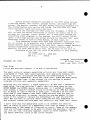
December 20, 1982
FRET')
HAr...;NAN.
10 Filosi ?oad
East Lvme~ Conn. 06333
Dear Mi ke:
I think Wes Steiners comment in IF #32 is appropiate.
The small cadre of authors submitting articles are those most deeply
interested in "High Tech" modifications~ disk ooerating systems~ etc.
which~ I believe~ are beyond the desires and understanding of the
majority of the membership. Since the "High Tech" trend has been going
on for quite some time, it may account for the decline in general
interest articles and~ possibly, membership.
Speaking only for myself~ I found nothing in IF #32 that I wanted to
read twice. The last articles I really dug into were yours on your
EPROM BURNER and SYMON. Again, echoing Wes~ if I wanted or needed a
disk system~ I wouldn~t bother trying to kludge up an 18lZ12 but would
buy an Apple or Lobo or Morrow or some such. I wouldn~t be too much
surprised if most members keep their 1802s because they are easy to
program and simplistic in design. Asking the average member to hang
disks on his system or replace his motherboard is just driving him
away. Not too many of us have really realized the full potential of
the original system and have been left behind by the "High Tech" group.
I don~t know what the membership count is at oresent but selling
ONLY 70 copies of Forth to a membership that used to number in the
neighborhood of 500 seems to illustrate mv point. Those of the members
that are fortunate enough to be able to attend the meetings in person
can iron out ~heir problems together, patch UP Forth together, etc ••
but where does that leave us who cannot attend?
•
.7
•
I believe you once stated that you did not wish to put large code
listings into IF. This was a good idea when the trend of the articles
was still fairly elementary. Now~ it might be the only way to get
usable~ working, programs out to the members and start raising our
programming abilities, as well as raising the interest level of members.
As far as I can recall~ the various monitors have been the only large
code articles in the past year or so that might be called "General
Interest". When was the last time a game article was printed? Any utility
program?
In memory serves me right~ the last membership survey showed that the
vast majority of members owned ELFs - either Netronics or Quest. Most
of these members are probably happy with their system as it is and are
not "High Tech" hardware tinkerers~ in spite of the fact that they
joined a club named "Association Of Computer-Chip E>:perimenters".
I guess what I am trying to say is that the FEW "High Tech" members are
leaving the MANY "Low Tech:' members behind and may be the only ones
left in the club in time.
I hope I have not offended you or anyone else but this is how I feel.
Dear Fred:
••
Thank you for your comments. I appreciate the time you took to write the only letter I received in response to my editorial.
You may be right, that most of our members don't appreciate "High Tech"
and need "Lo Tech" articles - but where do those articles come from?
HoW do people learn to be "High Tech"? I print what I get, wi thin an
issue or two of receiving it, and after I have verified that it works
I write what interests me and at my current level - as do most of oxu:
members. The sad truth is that few of our members care enough about the
Club to contribute anything to it, and quite possibly this will be the
last year we have a publication to turn to.
One of the great joys of being part of something is contributing to the
organization, and being recognized by others as contributing. I will
print anything and just about everything from the Membership. ACE came
into existence in response to a need for an information exchange on the
1802. We have been quite possibly the most prolific and diverse club
anywhere - we had to be, for there was no one else to support the 1802.
Perhaps the time has come for the club to fold and for you to go your
own way •••• I will be saddened by its passing.
Mike Franklin
•
8
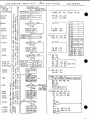
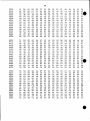
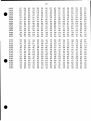
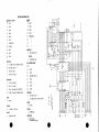
1861 Line Dra..ring Program
- by J. Munch, 20228 Clark Street, Woodland llills, Ca. USA 91367
I h r s pr o q r em demonstrates a
LINE DRt\WING program on the. ubiq,uitous 1861.
•
A subroutine (0016-0024) generates random values for a
zig-zag display. Inputs
XO, X1. YO and YI are used for the current line. ,Xl and Y1 are saved in RB to be
used the second time around as beginning points for the next line.
Many variations for inputting
a register and a d v artc i n q (4NL Then
as many lines as memory available/4
the range for X=OO to 3F, and for Y
the lines are possible,such as loading via
by storing each line (XO, Xl, YO, Yl> in a reg.
can be drawn. For the 1861 (in the lK mode)
the range is 00 to 7F.
The program has also been used with the 6847 chip in the Resolution Graphics Two
made, with but slight adJustment in the plot routine to account for the grid.
This mode has 128 pixels horizontally by 96 vertical where each dot is the size
of the c h ar-a c t e r-v p e r-Lo d " in the standard alpha-numeric mode.
On a standard TV set the pixels are square, an~ the available dots are six
times that of the 1861 operating with a 64 X 32 display.
Some background:
A search for a plot routine led me to an article in EON, May 27,1981, where
the RS Color Computer,also using the 6847, was discussed. Some 6809 machine code
showed how the plotting of points were performed. This code was then laboriously
~onverted to "1802".
Being able to plot dots on the screen, ur ib h Tinys VSR calls
Le d to a search for a line routine. Another article in the August 81 Byte,
Programming Guickies, by Mike Higgins, showed how to use his Form of the DDA,
(Digital Differential Anal~Jzer). A sample Basic p r-o q r am. where lines of any
•
slope between -1 and 1 !ould be drawn was given. Converting to Tiny was easy.
~1any evenings were spent playing around with variations of this Basic line
drawing method. The lina draw routine, now a proven program,was then written
in 1802 code, ~nd then made part of the code that the USR called.
From Basic it was then possible to generate lines by prOViding four inputs:
beginning points XO,Yl and end points X1,Y1.
(If XO=X1 and YO=Yl a single point is plotted)
******** THE 1861 IN THE HI-RESOLUTION MODE, 64 HOR 128 VERT. ************.llThe program uses one page for the code and four pages Tor th e display.
4
5 6 7
A B C 0 E F
0
1 2
3
8
9
. . . . . . . . . . . . . . . . . . . . . . . .. . .. . . . . . ..................................................
0000
90 131 B2 B3 D4 B7 B8 F8
FF A2 F8 27 1\3 F8 17 A7
FE 52 FE F3 FE 89 7E A9
0010
F8 El Ai B9 D3 00 03 99
F8 00 A4 F8 04 BA F8 FF
0020
99 7E B9 30 16 00 00 EA
0030
AA F8 00 73 9A 3A 31 lA
E2 69 D7 37 3B 84 FB iF
0040
01 AE BF 9B 52 A8 99 FA
32 27 14 F8 00 BE AF F8
3F BB F7 DO 33 5C FD 00
BD F8 FF 13F 8B 52 AA 89
0050
00 AD F8 FF AE 9D 52 80
FA 7F AB F7 AD 33 60 FD
0060
AD 9F BE 8E AF F8 00 AE
F5 33 81 90 AC 80 BD 8e
0070
73 88 73 F6 F6 F6 F9 F8
0080
BF 90 F6 BC Fe 01 AC 8A
F8
FO
07
A8
20 BA 8A FE AA 9A 7E BA
FC
52 88 FA
0090
04
52
F8
9A 75 BA 08 52 OA F1 5A
AA
OOP-,O
313 9A 8A F5
8C
52
90
F5 3B BD 3A 38 88 52 9F
AA
60
72
A8
FO
00130
52 80 F4 BC 1C 52 90 F5
F4 AS 8A 52 SF F4 AA 9C
OOCO
8A 52 BE F4 AA 30 87 72
3B 87 DC 88 5;::! 9E F4 1'.8
OODO
F8 01 130 F8 00 AO 30 OF
70 C4 22 78 22 52 E2 E2
OOEO
00 00 00 00 00 00 00 00
80 40 20 10 08 04 02 01
OOFO
•
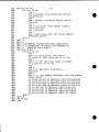
Ex e c u t e
•
REGISTER:
Rl
R2
R.3
R4
RS
.
. .
01
00
00
00
.
.
. .
00
El
FF
27
00 00
'-l"
i-.'::l
R7
R8
R9
RA
RB
RC
RD
RE
RF
Ple-ase refer to
OESeR IPTION:
VALVE:
.
f~O
Pres~ing INPUT KEY halts motion.
INP 1(69) @ 0039,
0000,
i~
00 17
00 <X )
El
01 (Y)
XX YY
{D3
(DX
(S1
(AI
Nt>
DY)
52)
A2)
..
.............
1861-DI'1A
INTERRUPT PTR
TOP OF STACK
START OF MAIN
R4. 1 NOT USED, R4.0=LINE CTR, (Us,er can adjust @ 003F)
SPARE REGISTER
SPARE REGISTER
RANDO!"l SUBROUTINE PTR.
RB. I=P IXEL P.~GE, R8. O=-=X COORDINATE
RANDOM REG, SEEDED WITH NON-ZERO (El>
RA. l=SCREEN PAGE{ 01 TO 04) , RA.O=:Y COORDINATE
RB. l=TEMPORARY X, RB.O=TEMPORARY Y, NEW BEGINNING PTS
LINE DRAWING REGISTERS.
"
II
II
II
"
II
LINE DRAWING REGISTERS .
. . . . . . . . . . . . . ..
flow chart.
....... ...... . ..
. . .
If this routine is to be modified for some other application it should noted
that HOt-1E is at; the lower left corner of the screen, 1st quadrant.
•
7F
1
I
I
1
1
I
1
.
Center:
..20,40 H
X
Y
I
I
I
I
1
I
I
I
00..... . . . . . . . . . . . . . . . . . . . . . . . . . . . . . . . . . . . . . :>3F
==================================================:=============================
new sub J ec t ...
T. Hills WINDOW
is a program that should have been delivered with any new
s'Jstem. Thank you ..
When bringing up Window, a usually flawless tape recorder, gave me a lot
of trouble. The problem was traced to a faulty lever arm inside the recorder,
The end result was to put WINDOW in EPROM. Some spare space ?? at 03F3 -03FF
and 04F2-04FF was used for a specific routine to down load Window to RAM @
{in my case)2000 H. Even if this space is used in Window, having it in RAM
should present no problems. Now that WINDOW is resident it is being put to good
use, probably more so now, than if it had been on tape.
Even if it takes a 6847, or similar display generator, to use WINDOW,
Comments on the line drawing program would be appreciated.
•
do it!
LINE DI2AwIN6~ p>CJINr PLCJT-
10
U5JNc;
S B/7 VALUES
:D7=
SIGN EIT
_._.
~-'---"-'------------
A~
Fg#¢rh l B E
J
S 2. A5
I lF7,
B'D
FS x¢
F B )( I
~.YES
~
ta070
Al
•
BF
9
:J~ LII----,
RI
..
nx = -t>X
t:,080
FS;l!,¢I. A~
R.4
=-1
~ F5!'{r!J
15L, AA
Fa YI F7,AlJ
YE'5
-"bY
.1 S'2.= - I
DY=
~/CJD
(;;/1
D
'->
fAtlO
,.DX =DY
N::. :D)(
DY; N
A'Z.= S2.
~/?lo 140
~/50,~O
(g I ~/I 70/70
,
~2.00
D~
1::,1../0
NI= I
, £l :: AI
, 52=0 AI =0
....
-:-
YESEXi?
~,
n:
RcsrOf(E.
REG/S1EES
~
)(0= ~O+AI
~
YO;:YO+AZ
ll.
D'3;D.,+:DY
~
R.
])3
NO)
FB#f=F , AE
R1J D'A
lJ'T
C
R. E 5/
'JD
sz
f<..,F
AI
Bb FE
~j
3D
It--------r
Ac;,
BlJ,
IJ:D, '1F BE ) 8£ AF
F8 ¢¢ I AE BF
a<
8])
52
AZ
•
~!)3i= D
LU
'-....,
FD ¢¢ , AD
-,(ES~
ct
~
l!.J
RB
Y (coR.
NI::NI+ I
~
S
SCREEN
4BA 73 98 73
'oS
~
Ir--~
PIX PIPE X Caie
=.DXjZ-
-
100
3~ I
R. ~
R. 9
R. A
••
~\
~
NO
D'.:>=DS-:DX
')(0.::)(0 +51
Yb =YO+S2.
•
___ ....-J
•
10
20
30
40
50
60
70
80
90
100
no
120
130
140
150
160
170
180
190
200
210
220
230
235
240
250
260
270
280
290
300
310
320
330
340
350
CLS: PRINT"
CRAPS" : PRINT
360
B=100
370
PRINT" A TOTAL OF 7 OR lION THE "
380
PRINT "FIRST THROW WINS. YOU CAN ALSO"
PRINT "WIN BY THROWING A 4, 5, 6, 8, 9, 10" 390
400
PRINT "AND MATCHING IT BEFORE THROWING"
410
PRINT "A 7. IF ON THE FIRST THROW A 2"
420
PRINT "3 OR 12 COMES UP, YOU LOSE."
430
PRINT "HIT LINE FEED TO CONTINUE";
440
X=INP(l)
450
IF x <>HOA GOTO 100
460
C=O:CLS
470
PRINT "ACCOUNT=$";B," "
480
INPUT "BET"B1
490
IF Bl>B GOTO 120
500
D1=INT (6*RND)+1
510
D2=INT (6*RND)+1
520
T=D1+D2
530
FOR N=l TO 10: PRINT : NEXT N
540
GOSUB 480
550
C=C+1
560
IF C>l GOTO 310
570
TO=T
580
WAIT (200)
590
IF T=7 GOTO 360
600
IFT=ll GOTO 360
610
IF T<4 GOTO 400
620
IF T=12 GOTO 400
630
CLS
640
PRINT "ACCOUNTO=$" ;B," ", "BET=" ;B1
650
GOTO 160
660
IF T=7 GOTO 400
670
IF T=TO GOTO 360
680
PRINT "TRYING TO MATCH" ;TO,C~ "ROLLS"
690
WAIT (250)
•
•
GOTO 280
B=B+B1
PRINT "********** YOU WIN **********"
PRINT"YOUR TOTAL=$";B:IF B>1000 PRINT"LET'S SEE THOSE DICE,YOut"
GOTO 440
B=B-B1
~.
PRINT " --------- YOU LOSE --------- YOU LOSE ------,---"
t1
PRINT "YOUR TOTAL =$";B
g'~
t1 t1
IF B<=O PRINT "THROW THE BUM OUT I "
o
INPUT "TYPE E'E' TO EXIT "E$
~i
l:7'CD
IF E$="E" END
..
Ul
rt
GOTO 120
a>tlIf
END
rt
V=@E065:D=D1: GOSUB 510
~ ....
.... n
V=@E072:D=D2: GOSUB 510
o .....
• w.....
RETURN
•o
FOR N=O TO 8
POKE (V+N,H43)
NEXT N
FOR N=l TO 4
Q=V+32*N
POKE (Q,H4F): POKE (Q+8,H4F)
NEXT N
Q=V+128
FOR N=l TO 7
POKE (Q+N,H43)
NEXT N
IF D>2*INT(D/2) POKE (V+68,H2E)
IF D=l RETURN
POKE (V+34,H2E): POKE (V+102,I2E)
IF D<4 RETURN
POKE (V+38,#2E): POKE (V+98,H2E)
IF D<6 RETURN
POKE (V+66,#2E): POKE (V+70,#2E)
RETURN
=
12
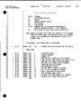
Cross Reference Chart - 1802 OP Codes to User Manual Page Number (MPC201C)
- by Derek Claridge, Nelson B.C.
•
ox
IX
2X
3X
4X
5X
6X
7X
8X
9X
AX
BX
ex
DX
EX
FX
38
16
16
31
18
20
16
41
17
17
17
18
35
39
39
19
42
41
36
21
32
19
35
22
33
20
36
22
i
18
33
I
; xo
I
!I xi
I
X2
'X3
I
i
34
26
38
25
i X4
34
28
38
27
; X5
34
24
37
23
x6
34
30
38
30
X7
32/37
'40
35/37
19
X8
34
41
36
21
X9
33
40
36
23
XA
33
39
36
22
XB
34
27
38
26
XC
34
29
38
28
XD
34
25
37
24
XE
34
31
37
30
XF
i
•
•
13
THE EIA RS-232-C STANDARD
•
AN INTERFACE BE'IWEEN mTA TERMINAL EQUIPMENr
AND
D!\TA <:Xlt1MUNlCATION EX;XJIPMENr
EMPIDYIliG SERIAL BINARY DATA INTERCHANGE
Published by
ELECIroNIC INOOSTRIES ASSOCIATION
Engineering Deparbnent
2001 Eye Street, N.W., Washington, D.C. 20006
August 1969
•
The following excerpts from the above Standard are provided to assist
yoo in applying RS-232-C canmunications on your micro.
Signal
D..1ring the transmission of data, the marking condition shall be used to
denote the binary state ONE and the spacing condition shall be used to
denote the binary state ZERO.
For timing and control interchange circuits, the function shall be
considered ON when the voltage (VI) is more positive than plus three
volts with respect to signal ground. The function is not uniquely
defined for voltages in the transition region between plus three volts
and minus three volts.
Signal Voltage
Binary State
•
Signal Condition
Function
Negative (-12v)
Positive (+12v)
1
Ma:r:king
OFF
0
spacing
ON
EIA RS-232-C STANDARD
14
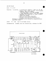
Interchange Circuits (defined by pin number of a Db 25 connector).
pins 1 to 7 and 20 form the "typical micro-computer circuit".
1.
DB25
•
Pin 1 - Protective Ground
Direction: Not applicable
This conductor shall be electrically bonded to the machine or
equipment frame. It may be further connected to external grounds
as required by applicable regulations.
2.
Pin 2 - Transmitted Data
Direction: TO data ccmnunication equipment (canputer to device).
Signals on this circuit are generated by the data terminal
equipment and are transferred to the local transmitting signal
converter for transmission of data to remote data terminal
equipment.
The data terminal equipment shall hold transmitted data in marking
condition during intervals between characters or words, and at all
times when no data are being transmitted.
In all systems, the data terminal equipment shall not transmit data
unless an ON condition is present on all of the following four
circui ts, where implemented:
1.
2.
3.
4.
•
Request to Send
Clear to Send
Data Set Ready
Data Terminal Ready
All data signals that are transmitted across the interface
Transmitted Data during the time an ON condition is maintained on
all of the above four circuits, where implemented, shall be
transmitted to the canmunication channel.
3.
Pin 3 - Received Data
Direction~ FROM data cammunication equipment (device to computer)
Signals on this circuit are generated by the receiving signal
converter in response to data signals received from remote data
terminal equipment via the remote transmitting signal converter.
Received Data shall be held in the binary ONE (Marking) condition
at all times when Received Line Signal Detector is in the OFF
condition.
On a half duplex channel, Received Data shall be held in the Binary
Q1.e (Marking) condition when Request to Send is in the ON condition
and for a brief interval following the ON to OFF transition of
Request to Send, to allow for the completion of transmission.
•
15
EIA RS-232-C STANDARD
•
4.
Pin 4 - Request to Send
Direction: TO data communication equipment (computer to device)
This circuit is used to condition the local data communication
equipment for data transmission and on a half duplex channel, to
control the direction of data transmission of the local data
communication equipment.
On one way only channels or duplex channels, the ON condition
maintains the data communication equipment in the transmit mode.
The OFF condition maintains the data communication equipment in a
non-transmit mode.
On a half duplex channel, the ON condition maintains the data
communication equipment in the transmit mode and inhibits the
receive mode. The OFF condition maintains the data communication
equipment in the receive mode.
5.
•
Pin 5 - Clear to Send
Direction: FROM data communication equipment (device to computer)
Signals on this circuit are generated by the data communication
equipment to indicate whether or not the data set is ready to
transmit data.
The ON condition, together with the ON condition On interchange
circui ts Request to Send, Data Set Ready and, where implemented,
Data Terminal Ready, is an indication to the data terminal
equipment that signals presented on Transmitted Data will be
transmitted to the communication channel.
The OFF condition is an indication to the data terminal equipment
that it should not transfer data across the interface on
interchange Transmitted Data.
The ON condi tion of Clear to Send is a response to the occurrence
of a simultaneous ON condition on Data Set Ready and Request to
Send, delayed as may be appropriate to the data communication
equipment for establishing a data communication channel (including
the removal of the MARK HOLD clamp from the Received Data
interchange circuit of the remote data set) to a remote data
terminal equipment.
6.
•
Pin 6 - Data Set Ready
Direction: FROM data communication equipment (device to computer)
Signals on this circuit are used to indicate the status of the
local data set.
EIA RS-232-C STANn.2W>
16
1he ON condition on this circuit is presented to indicate that a)
the local data communication equipment is connected to a
canrmmication channel ("OFF HOOK" in switched service),
AND b)
the local data communication equipment is not in test (local or
remote), talk (alternate voice) or dial* mode.
AND c)
the local data communication equipment has completed, where
applicable:
1.
any timing functions required by the switching system to
canplete call establishment, and
2.
the transmission of any discreet answer tone, the duration
of which is controlled solely by the local data set.
7.
Pin 7 - Signal Ground or Cammon Return
Direction: Not applicable.
8.
Pin 20 - Data Terminal Ready
Direction: TO data canmunication equipnent (canputer to device)
Signals on this circuit are used to control switching of the data
communication equipment to the communication channel. The ON
condi tion prepares the data communication equipment to be connected
to the communication channel and maintains the connection
established by external means (e.g., manual call origination,
manual answering or automatic call origination).
~
~
When the station is equipped for automatic answering of received
calls and is in the automatic answering mode, connection to the
line occurs only in response to a combination of a ringing signal
and the ON condition of Data Terminal Ready. However, the data
terminal equipment is normally permitted to present the ON
condition on Data Terminal Ready whenever it is ready to transmit
or receive data, except as indicated below•.
The OFF condition causes the data communication equipment to be
removed from the canmunication channel following the completion of
any "in process" transmission. The OFF condition shall not disable
the operation of Ring Indicator.
*
The data communication equipment is considered to be in the dial mode
when circuitry directly associated with the call origination function
is connected to the communication channel. These functions include
signalling to the central office (dialing) and monitoring the
communication channel for call progress or answer back signals.
..
W'
17
EIA RS-232-C STANDARD
•
The following signals are typically implemented in a modem installation:
1.
Pin 8 - Received Line Signal Detector
Direction: FROM data communication equipment (device to computer)
The ON condition on this circuit is presented when the data
communication equipment is receiving a signal which meets its
suitability criteria. These criteria are established by the data
communication equipment manufacturer.
The OFF condition indicates that no signal is being received or
that the received signal is unsuitable for demodulation.
The OFF condition of Received Line Signal Detector shall cause
Received Data to be clamped to the Binary One (Marking) condition.
The indications on this circuit shall follow the actual onset or
loss of signal by appropriate guard delays.
•
On half duplex channels, Received Line Signal Detector is held in
the OFF condition whenever Request to Send is in the ON condition
and for a brief intervai of time following the ON to OFF transition
of Request to Send.
2.
Signals on this circuit are used to provide the data terminal
equipment with signal element timing information. The data
terminal equipment shall provide a data signal on Transmitted Data
in which the transitions between signal elements nominally occur at
the time of the transitions from OFF to ON condition of the signal
on the circuit. When this circuit is implemented in the DCE, the
DCE shall normally provide timing inf~rmation on this circuit
whenever the DCE is in a POWER ON condition. It is permissible for
the DCE to withhold timing information on this circuit for short
periods, provided Data Set Ready is in the OFF condition. (For
example, the withholding of timing information may be necessary in
performing maintenance tests within the DCE).
3.
•
Pin 15 - Transmitter Signal Element Timing (DCE Source)
Direction: FROM data communication equipment (device to computer)
Pin 17 - Receiver Signal Element Timing (DCE Source)
Direction: FROM data communication equipment.
Signals on this circuit are used to provide the data terminal
equipment with received signal element timing information. The
transition from ON to OFF Condition shall nominally indicate the
center of each signal element on Received Data. Timing information
on the circuit shall be provided at all times when Received Line
Signal Detector is in the ON condition.
4.
Pin 21 - Signal Quality Detector
Direction: FROM data communication equipment (device to computer)
18
EIA RS-232-C STANDARD
Signals on this circuit are used to indicate whether or not there
is a high probability of an error in the received data.
•
An ON condition is maintained whenever there is no reason to
believe that an error has occurred.
An OFF condition indicates that there is a high probability of an
error. It may, in SOme instances, be used to call automatically
for the retransmission of the previously transmitted data signal.
Preferably the response of this circuit shall be such as to permit
identification of individual questionable signal elements on
Received Data.
5.
Pin 22 - Ring Indicator
Direction: FROM data communication equipment (device to computer)
The ON condition of this circuit indicates that a ringing signal is
being received on the communications channel.
The ON condition shall appear approximately coincident with the ON
segment of the ringing cycle (during ri ngs) on the communi cation
channel.
The OFF condition shall be maintained
r Lngfng cycle (between "rings") and at
is not being received. The operation
disabled by the OFF condition on Data
6.
during the OFF segment of the
all other times when ringing
of this circuit shall not be
Terminal Ready.
•
Pin 23 - Data Signal Rate Selector (DTE Source)
Direction: TO data communication equipment (computer to device)
Signals on this circuit are used to select between the two data
signalling rates in the case of dual rate synchronous data sets or
the two ranges of data signalling rates in the case of dual range
non-synchronous data sets.
An ON condition shall select the higher data signalling rate or
range of rates.
The rate of timing signals, if included in the interface, shall be
controlled by this circuit as may be appropriate.
7.
Pin 23 - Data Signal Rate Selector (DeE Source)
Direction: FROM data communication equipment (device to computer)
Signals on this circuit are used to select between the two data
signalling rates in the case of dual rate synchronous data sets or
the two ranges of data signalling rates in the case of dual range
non-synchronous data sets.
An ON condition shall select the higher data signalling rate or
range of rates.
The rate of timing signals, if included in the interface, shall be
controlled by this circuit as may be appropriate.
•
19
EIA RS-232-C STANDARD
•
8.
Pin 24 - Transmitter Signal Element Timing (DIE Source)
Direction: TO data communication equipment (computer to devi ce)
Signals on this circuit are used to provide the transmitting signal
converter with signal element timing information.
The ON to OFF transition shall nominally indicate the center of
each signal element on the Transmitted Data. When the circuit is
implemented in the DTE, the DTE shall normally provide timing
information on this circuit whenever the DTE is in a POWER ON
condition.
It is permissible for the DTE to withhold timing
information on this circuit for short periods, provided Request to
Send is in the OFF condition.
(For example, the temporary
withholding of timing information may be necessary in performing
maintenance tests within the DTE).
The following signals are typically a duplicate or secondary circuit.
1.
•
Pin 12 - Secondary Received Line Signal Detector
Direction: FROM data communication equipment (device to computer)
This circuit is equivalent to Received Line Signal Detector except
that it indicates the proper reception of the secondary channel
line signal instead of indicating the proper reception of primary
channel received line signal.
2.
Pin 13 - Secondary Clear to Send
Direction: FROM data communication equipment (device to computer)
This circuit is equivalent to Clear to Send except that it
indicates the availability of the secondary channel instead of
indicating the availability of" the primary channel. This circuit
is not provided where the secondary channel is useable only as a
circuit assurance or an interrupt channel.
3.
Pin 14 - Secondary Transmitted Data
Direction: TO data communication equipment (computer to device)
This circuit is equivalent to Transmitted Data except that it is
used to transmit data via the secondary channel.
4.
Pin 16 - Secondary Received Data
Direction: FROM data communication equipment (device to computer)
This circuit is equivalent to Received Data except that it is used
to receive data on the secondary channel.
•
5.
Pin 17 - Secondary Request to Send
Direction: TO data communication equipment (computer to device)
This circuit is equivalent to Request to Send except that it
requests the establishment of the secondary channel instead of
requesting the establishment of the primary data channel.
TINY PILOT V1.0
UTILITY SUBROUTINES
1
2
=
RC1802-V01D
00 00
20
PILOT.RCA
07-NOV-82 11:58:15
.ORG
10000
.TITLE TINY PILOT V1.0
3
;
;
4
5
6
7
1 802
TIN Y P I LOT
PAGE
•
ORIGINAL AUTHOR: R. W. PETTY
REVISION HISTORY:
8
9
10
11
12
13
14
15
16
17
18
19
20
21
;
;
;
22
23
24
25
26
27
28
29 0000 30 16
30 0002 30 33
31
32
;
-;
SEP./82 W. BOWDISH - REARRANGED CODE TO CONSOLIDATE FREE
T. HILL
SPACE AND MADE MINOR CODING CHANGES
- ADDED EDIT MODE REPLACE LINE COMMAND
- ADDED EDIT MODE COMMAND TO PRINT THE
ADDRESS OF THE LAST USED BYTE IN THE
TEXT BUFFER
- ADDED PILOT CALL TO SCRT CALLABLE
MACHINE LANGUAGE SUBROUTINES
TINY PILOT HAS 2 ENTRY POINTS ( COLDST AT 10000 AND WARMST AT
10002 ). IF THE PROGRAM IS ENTERED AT 'COLDST', THEN THE SCRT
REGISTERS AND STACK POINTER ARE INITIALIZED AND THE DATA PAGE
AND TEXT BUFFER ARE INITIALIZED. IF THE PROGRAM IS ENTERED AT
'WARMST' THE SCRT REGISTERS AND STACK POINTER ARE ASSUMED TO
BE SET UP AND THE CONTENTS OF THE TEXT BUFFER ARE PRESERVED.
*NOTE* TINY PILOT USES A MODIFIED SCRT CALL/RETURN TECHNIQUE
TO SAVES/RESTORES REGISTER-7 ACROSS A CALL AND RETURN
;
COLDST: BR
WARMST: BR
PILINZ ; COLD START ENTRY POINT
PILWRM ; WARM START ENTRY POINT
•
BRANCH VECTORS FOR EXTERNALLY DEFINED SUBROUTINES
33
34
35
36
37
38
39 0004
40
41 0007
42
43 OOOA
44 OOOD
45
46 0010
47
48 0013
49
50
;
;
;
THE FOLLOWING TABLE CONTAINS LONG BRANCHES TO ROUTINES WHICH
MUST BE SUPPLIED BY THE USER. THESE ROUTINES ARE CALLED USING
THE SCRT CALL/RETURN TECHNIQUE. BEFORE USING TINY PILOT THESE
BRANCH VECTORS MUST BE MODIFIED TO POINT TO YOUR SUBROUTINES.
CO 07 70
TTYOUT: LBR
CO 07 69
TTYINP: LBR
CO 00 F6
CO 81 A4
CRLF: LBR
CASOUT: LBR
CO 81 40
CASINP: LBR
CO 10 00
MONXIT: LBR
.SLW
OUTCHR ;
;
INPCHR ;
;
$CRLF ;
181A4 ;
;
18140 ;
;
11000 ;
;
TERMINAL CHARACTER OUTPUT ROUTINE
( CHARACTER PASSED IN D-REG. )
TERMINAL CHARACTER INPUT ROUTINE
(CHARACTER RETURNED IN D-REG. AND RF.HI)
<CR><LF> OUTPUT ROUTINE
CASSETTE CHARACTER OUTPUT ROUTINE
( CHARACTER PASSED IN D-REG. )
CASSETTE CHARACTER INPUT ROUTINE
(CHARACTER RETURNED IN D-REG. AND RF.HI)
ENTRY POINT TO SYSTEM MONITOR ( EDIT
MODE "M" COMMAND EXITS VIA THIS LBR)
•
1
TINY PILOT V1.0
UTILITY SUBROUTINES
.~
3
;
4
5
;
RO-R6
R7
R8
R9
RA
RB
RC-RE
7
8
9
10
11
.~
28
29
30
31
32
33
34
35
36
37
38
39
40
41
•
PILOT.RCA
REG 1ST E R
6
12
13
14
15
16
17
18
19
20
21
22
23
24
25
21
RC1802-V01D
RF
;
;
;
07-NOV-82 11:58:15
USE AGE
STANDARD
SAVE/RESTORE REGISTER
SCRATCH
GENERAL PURPOSE COUNTER
TEXT POINTER
LINE POINTER
RESERVED FOR I/O AND PASSING PARAMETERS TO
MACHINE LANGUAGE ROUTINES ( VIA S: COMMAND )
RF.HI HOLDS I/O ASCII CHAR. AND D-REG FOR SCRT
NOTE: NUMERIC VARIABLES ARE SINGLE BYTE ENTRIES IN THE VARIABLE
PAGE WITH OFFSET EQUAL TO THEIR ASCII CODES. IE. VARIABLE
A <+41) IS AT ADDRESS +XX41 AND VARIABLE Z (+5A) IS AT
ADDRESS tXX5A
FOR ASSEMBLY, THIS SYMBOL SHOULD BE REDEFINED
=
;
00 20
TOPMEM: •EQL
120
HIGHEST RAM PAGE AVAILABLE FOR TEXT BUFFER
ERROR CODES
;
=
=
=
=
=
=
=
=
=
=
=
=
=
=
=
00
00
00
00
00
00
00
00
00
00
00
00
00
00
00
01
02
03
04
05
06
07
08
09
OA
OB
OC
OD
OE
OF
.ERDZRt
.ERCMDt
.ERFUL:
.ERNNV:
.ERNTVt
.ERBNV:
.ERBTV:
.ERNRT:
.EREXP:
.ERNVR:
.ERNEQ:
.ERNLBt
.ERBLB:
.ERUSRt
.ERMXtt:
.EQL
.EQL
.EQL
.EQL
.EQL
.EQL
.EQL
.EQl
.EaL
.EQL
.EQL
.EQL
.EQL
.EQL
.EQl
.SLW
1
2
3
4
5
6
7
8
9
10
11
12
13
14
15
;
;
;
;
;
;
;
;
;
;
;
;
;
;
;
DIVISION BY ZERO
INVALID COMMAND
MEMORY FULL
BAD NUM. VAR. SYNTAX IN TYPE STATEMENT
CAN'T FIND (OR BAD SYNTAX) TEXT VAR. IN TYPE
BAD NUM. VAR. SYNTAX IN ASK STATEMENT
BAD TEXT VAR. SYNTAX IN ASK STATEMENT
UNDEFINED RETURN STATEMENT
BAD EXPRESSION SYNTAX
NO VAR. NAME IN COMPUTE STATEMENT
NO 1:1 SIGN IN COMPUTE STATEMENT
CAN'T FIND lABEL OF JUMP OR USE
BAD STATEMENT lABEL SYNTAX
NO ADDR. OR SYNTAX ERROR IN lSI COMMAND
ERROR IN MAX. MEMORY SPECIFICATION
PAGE
22
PILOT EDIT MODE C01MANDS
•
COMMAND
SYNTAX
FUNCTION
BEGIN
B
move text po irit.er to start of
display current ( first ) line
CLEAR
C
clear text buffer ( Le , delete all program lines
currently in the text buffer
Dam
Dnnn
move text po i.rrcer down 'nnn' lines and display new
current line. If there were less than 'nnn' lines
of text after the text po inter then the text
podrit.er is pos Lt.Loned immediately after the last
character of the last line.
END
E
move text p:>inter to end of text. The text p:>inter
is left pointing to the byte past the last entered
program byte.
HIGH
H
display the address ( in hex ) of the last byte
used in the text buffer. This is useful if you are
going to use a monitor cassette dump routine to
write out the contents of the text buffer. Note
that the text buffer starts at address #0900.
INSERT
I<text>
insert one line of <text> in front of the curre.
line.
KILL
Knnn
kill ( delete ) 'nnn' lines of text, starting at
the current line, and display the new current line.
LOAD
L
load text from cassette. The text lines are
appended to the text currentlyy in the text buffer.
MONITOR
M
return to the system monitor
PILOT
P
execute the pilot program
REPLACE
R<text>
replace the current line with the line <text>
STORE
S
store entire
cassette.
UP
Unnn
move text pointer up , nnn' lines and display new
current line. If there were less than 'nnn' lines
of text above the text pointer, then the pointer is
p:>sitioned at the start of the first line.
WRITE
Wnnn
write 'nnn' lines to the tenninal starting with the
current line. The position of the text po irrt.er' is
not changed.
•
note:
nnnn
represents a number in the range 0 to 255
<text>
represents a line of text up to 60 characters long
contents
of
the
text
text
buffer
buffer
and
on
23
PILOT INSTRUCTIONS
•
COMMAND
SYNTAX
FUNCTION
ASK
A:
Request input from the tenninal. The input is not
saved in a variable but is available for matching
( see the M: canmand ).
A:#v
request numeric input from tenninal and store in
numeric variable 'v'
A:$v
request string data
string variable 'v'
CCMPUTE
C:n=exp
compute the value of the expression ' exp'
assign the value to numeric variable 'n'.
END
E:
stop execution of program. This canmand may be
placed anywhere in the program Where execution
should logically stop.
JUMP
J:exp
jump ( branch ) to statement with the same label
number as the value of the expression 'exp'.
CONTROL
K:exp
output the ASCI I equ i valent of the value of 'exp ,
to the tenninal. The control canmand may be used to
output any ASCII character to the tenninal.
from
tenninal
and
store
in
and
ex. K:13 outputs a carriage return to the tenninal
MATCH
M: sl ( , s2 ••• )
compares the strings 'sl'
's2'. •• to the
response from the previous ask canrnand. If a match
is found the match flag is set 'yes' otherwise the
match flag is set 'no'.
NO
cN:xxx
if the match flag is set to 'no' then the command
c:xxx is executed. 'c' represents any pilot canmand
and ' xxx' represents any text required by the
canmand. for example:
IN:123 will jump to the statement labeled %123 if
the match flag is set to 'no'. If the match flag is
set to 'yes' the jump canmand will not be executed
and the next sequential statement will be executed.
RETURN
•
R:
Return from subroutine ( see USE canmand )
SCRT CALL S:laddr(,al,a2,a3) calls a machine language subroutine using
the S.C.R.T. technique. 'addr' is the address of
the machine language subroutine in hex. ' an ' are
optional arguments of the fonn #v or $v ( Le ,
either numeric or string variables). The addresses
of the arguments are passed in registers RC, RO,
and RE.
24
TYPE
T:(text) (:jf:v)($V)(i) type text and/or variables on the
terminal. Text and variable may be present on the
cannand line in any order. A carriage return and
line feed are output at the end of the line unless
a semi-colon I i ' is placed at the end of the line
in WhiCh case the carriage-return/line-feed are
suppressed.
USE
U:exp
call a pilot subroutine with a label number equal
to the value of the expression 'exp I . Subroutines
can be nested to a depth of 24.
EXAMINE
X:exp
sets match flag to 'yes' if 'exp' evaluates to 0
otherwise the match flag is set to 'no'
•
X:v«>=exp) sets the match flag to 'yes' if the condition is
true, otherwise the match flag is set to 'no'.
YES
cY:xxx
if the match flag is set to 'yes' then the canrnand
c:xxx is executed. 'c' represents any pilot command
and ' xxx' represents any text required by the
command. for example:
JY:123 will jump to the statement labeled %123 if
the match flag is set to 'yes'. If the match flag
is set to 'no' the jump command will not be
executed and the next sequential statement will be
executed.
RANIXM Z
Z:exp
assigns a randan number in the range 0 to 'exp'-l
to the numeric variable Z.
note:
exp
represents an expresion consisting of constants
and/or numeric variables with operators + - * and
/. Expressions are evaluated fran left to right and
must evalute to a value in the range 0 to 255.
(xxx)
represents an optial part of a statement
tv
represents a numeric variable
$v
represents a string variable
v
variable names are the upper case letters A to Z
%nnn
line labels consist of a number in the range 0 to
255 preceeded by a percent sign. Statements need
not be labeled but if they are the label must
preceed the command. For example:
%123 T:HI
•
•
25
•
•
•
03
B6
86
5F
D5
00
OA
70
F8
9A
D4
3F
D4
3C
49
02
03
83
A3
AF
F8
04
F8
CO
lC
A4
00
D4
01
42
02
68
03
A6
72
F8
09
30
OD
07
A3
F8
D6
00
6E
0'')
.:.
6E
53
9F
46
A7
00
BA
El
D4
69
90
BO
D4
04
D4
2D
4B
02
D3
B3
72
2F
F8
D4
00
CO
93
A5
()O
D4
01
43
03
94
BF
46
B7
5F
00
00
04
00
D3
F8
£9
00
01
00
4A
55
E2
A3
38
01
89
99
00
F4
68
D4
FB
F8
32
D4
EA
C5
30
0".:.
lB
CO
B9
B7
04
B9
52
00
04
20
74
00
F8
F8
D9
D5
OB
03
F8
D4
D5
D5
46
07
32
5B
30
OA
03
01
93
D4
FB
03
64
01
89
F8
20
D5
D4
17
52
01
Fa
FB
17
lB
87
6E
32
32
46
01
89
32
B8
01
F8
19
D4
D5
D5
08
00
32
03
FB
73
D4
97
01
9F
D4
32
3A
01
OA
4A
FB
OA
5F
03
03
FB
00
FB
13
5A
02
F7
E6
F6
FF
57
03
D5
FB
30
3A
02
D6
03
38
FB
34
2A
lA
9A
41
17
32
D4
OE
04
73
3A
4A
32
lA
03
48
OA
D4
58
3B
FB
43
03
3A
F8
9A
82
87
Bl
9A
3A
FB
FB
02
0000
0010
0020
0030
0040
0050
0060
0070
0080
0090
OOAO
OOBO
OOCO
OODO
OOEO
OOFO
30
CO
FF
D4
32
00
A7
45
00
CB
97
BF
AE
00
D5
44
16
81
A2
00
51
F8
4B
01
13
03
73
E2
F8
D6
46
49
30
40
93
CF
D4
3E
D4
13
50
03
87
12
08
F8
32
54
33
CO
B4
D4
01
D4
01
48
03
03
73
96
BF
03
EO
00
CO
10
B5
00
21
00
D8
03
FB
03
93
B3
F8
5A
D4
30
07
00
F8
Cl
F8
04
30
3D
0100
0110
0120
0130
0140
0150
0160
0170
0180
0190
01AO
01BO
01CO
01DO
OlEO
01FO
D5
61
D5
99
89
19
AF
OC
FB
00
B9
00
46
32
32
D3
D4
AB
F8
30
F9
F7
89
Fa
15
04
87
04
B7
D7
E6
D4
01
D5
00
41
30
33
52
00
32
30
FA
30
46
lA
17
01
OC
D4
A8
A9
D4
50
30
A7
B9
74
03
74
A7
30
17
5A
0200
0210
0220
0230
0240
0250
0260
0270
0280
0290
02AO
02BO
02CO
02DO
02EO
02FO
F8
48
00
9A
04
30
D5
B7
02
OD
97
98
FB
9A
D5
3A
08
BA
D5
B8
30
4A
D4
8A
57
3A
D4
2A
OA
B8
D4
E7
B8
08
F8
8A
34
FB
01
A7
2A
73
00
D5
32
8A
03
29
D5
AA
01
A8
D4
03
CO
4A
72
D5
OD
D4
B8
A8
23
89
co.')
iJ.:.
AF
5:8
94
17
94
30
F3
D5
0::"")
.:I.:.
~S8
08
08
8"7
\)4
32
F8
D5
07
EC
t)2
18
~)
")
"-"-
03
FE!
23
51
01
FB
17
F8
FE!
FB
B"7
03
02
30
CO
08
D4
01
D4
B7
8F
AA
OA
F8
F6
F8
OC
D4
OA
93
CF
4C
02
96
30
A6
3A
Fa
D4
OA
05
AF
33
3A
57
46
BF
32
FB
00
74
OD
8"7
FB
AS
FE
D5
F8
F8
3F
F8
52
FO
A8
3£
04
27
5B
F3
03
D8
:;2
F8
08
OA
88
00
Fa
5F
fB
3').:.
87
2:8
D4
32
32
4·7
F8
08
:8F
D4
32
A9
00
8A
OA
3A
OE
32
29
A9
20
02
FF
OE
58
FF
D5
5B
DS
43
D1
3A
03
FB
4B
27
97
FB
03
29
2A
F8
D1
33
D1
48
0').:..
51
56
07
5A
87
F8
D4
23
89
OA
03
~O
D5
32
32
D5
'/2
")1:
.:..:1
32
30
89
D4
32
57
A7
3A
32
D1
EO
F6
~~A
44
02
El
73
98
FO
C'l
02
00
D4
D~5
10
B9
FB
Fa
00
D....
Fl
B3
OF
..I
8:1.
B2
00
19
01
Fa
02
B3
A4
Fa
O~
86
9F
B6
D5
5A
El
00
00
5A
67
47
4D
02
73
113
30
Dft,
lA
45
04
B13
OF
01
46
9"7
30
D4
32
4B
3E
08
OA
97
47
4"7
F4
F8
A9
33
18
38
67
01
B4
D4
32
D4
D5
F3
F3
A3
A8
0:1
F6
F8
D6
00
30
2A
9A
F8
FB
9C
30
10
EO
D4
OD
D4
57
22
00
D4
51
38
EA
52
lA
3A
OA
00
32
3A
FB
SA
26
0300
0310
0320
0330
0340
03S0
0360
0370
0380
0390
03AO
03E<0
03CO
0300
03EO
03FO
01
OF
F8
32
9A
03
97
FE<
OA
30
32
30
OA
7E
01
OS
SA
B9
01
2B
D4
S6
E<A
07
DS
66
AC
66
F3
38
CO
D4
03
89
DS
87
OS
D4
87
32
lA
1A
FE<
D4
3A
lA
3D
01
[IS
FE
D4
3A
EC
02
AA
82
OA
9A
29
01
E<S
OA
00
SA
B9
FE
01
3E<
8A
30
ItS
F8
[14
B7
32
13
DS
FB
3A
OA
FF
S2
OC
99
D4
[IS
38
0400
0410
0420
0430
0440
04S0
0460
0470
0480
0490
04AO
04E<0
04CO
0400
04EO
04FO
Cl
01
FB
E<7
00
30
01
00
55
F8
02
lS
07
03
32
24
04
CO
4E
F8
38
D4
32
4B
OS
3F
00
3A
OS
E<2
ES
SA
02
3A
32
65
2A
00
19
05
3D
04
04
B8
lA
3A
lA
lA
04
03
5D
A7
OA
E9
30
SE
58
00
01
OA
9A
EC
30
98
OSOO
OSlO
OS20
0530
0540
0550
0560
0570
0580
0590
05AO
05BO
05CO
05DO
05EO
05FO
D4
27
OA
DS
02
32
05
OA
8F
01
FB
B4
01
SA
A7
F6
06
1A
D4
F8
FC
59
3A
FE<
lB
04
2C
4B
65
05
89
D4
OS
OA
02
00
01
FF
67
OD
OB
01
32
32
5F
F8
FE
05
3A
04
04
A9
04
01
89
32
FE<
65
AA
E<1
B7
00
A9
F6
3B
F4
00
OD
EC
E<7
OA
81
3A
114
D4
01
SA
02
D4
01
20
FE
A9
3A
30
8A
FB
OA
CS
03
00
CO
04
04
06
tiA
99
AC
lA
04
20
F6
{IS
30
89
F8
FE<
OS
9A
1A
32
15
A7
OA
D4
01
32
1A
D4
D4
3A
OA
99
FE<
D5
OE<
40
06
04
CO
04
E<7
9A
09
SA
01
51
FE<
D4
02
D4
41
OS
84
04
23
01
8A
E<7
04
lA
13
04
S9
01
32
01
04
68
SA
01
OD
60
A7
8A
02
F8
lA
02
32
D8
4Il
19
90
52
05
6E
3A
OS
07
A7
2S
03
F8
04
S5
[14
OA
01
43
05
AB
1.14
E<7
D4
04
27
97
5A
03
26
03
F8
4A
01
04
04
8F
00
01
47
B9
04
A7
97
60
89
04
00
04
65
01
00
D4
3A
OS
52
FA
06
97
F6
FO
E<7
3A
DS
03
02
65
04
01
7C
9B
48
01
05
32
B7
FA
D4
2C
[14
04
04
02
05
OC
04
B8
F3
52
3A
E9
30
OF
00
D4
01
32
05
DS
F8
9A
01
88
32
99
Dl
FA
D5
FC
18
02
8A
ti2
A'7
2C
7E
A7
OD
04
on
e;
B"
O'~
24
30
02
os
OB
2A
on
01
FB
32
03
4C
03
01
1A
01
02
OA
BA
£14
06
05
5A
34
00
D4
00
B7
CO
A8
9A
FE
04
()1
87
30
FF
99
38
19
D4
It4
3 r"-l
00
D4
JA
30
03
7£
lS
3A
})S
3A
F4
17
89
03
02
7E
04
01
CE<
9C
3A
04
3A
FO
04
33
A9
4B
05
23
51
FB
30
ln
lA
97
C4
01
Fl
97
00
20
F8
D'1
D4
32
D4
29
66
D4
OA
BA
07
5A
4A
04
D6
99
00
03
01
5A
OA
B9
19
OD
OB
Dl
53
03
CO
D4
5A
lS
FE<
87
01
04
FB
04
()O
3A
.30
02
20
02
32
lA
19
03
06
3A
03
AA
01
J'"l
e:
D4
D4
OD
32
OD
OB
If.:
D4
61
54
03
32
OA
D4
07
£S
01
02
D4
31
OC
2A
32
01
04
SA
2C
07
D5
3B
01
32
A9
52
01
97
OS
2A
58
5A
01
A7
on
FB
D4
BE
47
El
05
FO
CO
52
D4
D5
D4
08
65
[14
3')s:
00
01
FC
99
87
73
39
25
89
01
04
01
D5
01
05
6F
32
19
01
D4
52
F6
02
4~
06
03
:~4
4:~
19
0'·)
C5
03
OD
23
ItS
<.
Bn
52
02
"7')
\J ':.
04
01
FE<
87
52
0::,
E<7
01
D4
HI
D4
D4
01
4n
03
03
C2
D4
01
BH
FE<
1 ~~
6E
O;~
F3
Sn
01
19
04
38
96
ns
AA
5F
F3
01
89
F6
CF
FA
D5
0<1.
13
D4
25
92
00
21
OD
AA
lA
30
04
60
00
D4
OA
93
02
02
1<7
05
65
03
04
02
5_
04
27
F8
ItS
3A
3A
OD
19
02
06
lA
32
F8
07
3A
D4
65
F4
F6
FC
•
27
•
'.
•
00
32
32
02
It5
OA
32
52
30
31
52
01
Bl
BS
AC
32
04
43
OA
15
97
OA
71
89
OA
32
89
It4
30
04
04
F7
05
FB
FB
32
A9
04
27
F5
04
B8
F5
01
AO
07
07
BE
FS
31
06
53
FS
01
S7
30
06
FB
32
65
04
01
29
8F
00
32
B3
B7
S9
33
BC
33
04
20
15
04
01
30
S7
97
B7
FB
97
FS
32
FC
SF
FC
05
07
FE
lA
3A
9A
S7
'FS
20
FA
50
FS
99
00
50
4C
04
3B
Fl
OA
26
Bl
AA
9F
5C
3F
05
20
lC
FB
20
SF
07
26
AF
FB
4A
SA
9F
AD
9F
5C
FS
5F
30
E2
FS
lF
06
FF
FC
24
AF
A7
CS
FS
FB
lC
FF
lF
99
32
El
9C
33
06
00
32
FS
D4
Fa
OS
OS
9C
BF
9F
SC
(lC
50
FB
26
33
05
49
OS
03
00
BIt
32
FB
FS
FB
FA
FB
10
4A
26
FF
OA
BF
B2
FC
1\ It
BB
E2
00
E2
EO
E2
FS
.3A
0600
0610
0620
0630
0640
0650
0660
0670
06S0
0690
06AO
06BO
06CO
0600
06EO
06FO
07
FB
FB
OA
FS
A7
27
81
S9
0700
0710
0720
0730
0740
0750
0760
0770
07S0
0790
07AO
07BO
07CO
0700
07EO
07FO
co
E2
3~)
s:
OA
00
lA
32
81
05
02
AA
01
01
33
33
AE
B7
43
4S·
04
115
A9
77
(14
3A
32
3B
U5
co
FC
FC
9S
FF
FC
00
FB
30
:~A
00
BC
FB
32
AF
3A
AC
BC
EO
FO
A7
FB
FB
03
F8
.30
27
05
B3
BA
BO
27
21
AS
32
86
38
01
0"7
04
01
50
30
D2
FS
lA
27
30
06
05
23
62
26
05
OIt
05
DE
AC
BO
SC
3B
FC
01\
lA
lA
3C
AC
32
F8
FS
30
FC
FO
t~C
BC
SF
BF
AC
~~S
OD
\)4
F7
8S
:~A
lA
32
32
32
C8
04
7I:1
89
00
89
S'7
17
3A
07
BIt
A6
OA
13
4B
::iA
F8
05
97
FB
FB
FB
D4
02
31
5.2
~30
81
A7 OA
B7 [14
32 Bl
30 99
FC 1(\
29 33
SF . Afl
))5 04
20
03
05
01
C8
S7
89
D4
FB
06
F8
17
01\
FC
26
OA
01
26
OA
9A
69
9F
C4
::iF
02
99
20
30
FS
9F
FF
3B
FE
OD
D4
15
AF
7F
32
32
:iIt
EO
FB
tj2
co
lA
It4
BF
69
FB
FB
5C
5F
2C
3B
99
20
BC
OA
SF
2C
OA
02
8A
F(.)
OC
07
8C
F8
9C
09
BC
AC
30
D4
01
52
CS
FS
BO
32
32
32
5A
F8
32
F4
01
on
05
00
30
0'7
32
0'/
5A
19
FE
3t-l
02
3A
97
O~j
A2
99
2D
BF
[IF
9C
FS
00
00
OA
43
4E
09
03
6B
30
47
32
3A
30
AA
01
F7
29
OE
FF
FE
64
15
26
BA
C4
F8
9F
9C
BC
3A
7C
EO
AF
00
OUT F' 1...1 T
'.; 'I
'J
-r
F F=- > !<:1:2/
T
p ::;' :::' p
J. J. J.
~::
T:f'F'F'
-rtF'
F'
U:20/
TOP
F'
U:20/
T:F'F'F'F'
U:20./
T~F'
.
L.
TTTTT
T
I
I-
T
I
L
I
L
r.L
L
I
L
'.,}
III
X:·~:O
o
o
o
a
LLLLL
0
T
0
T
0
T
0
T
000
•
T
" ..:..... /
J::LO
:.:~20
1
.L
II' '7'0,1
T i is .
U:20/
T" c·
u120
T
:
I I + ,••) t\
28
C:T=150
--------
CiT::::T-l
X~T=O
,IN: 30
R:
r i'···~ RC :1\: 0 C
L '.'
~. :::
I:' R'"\
.: f. .:: 2
; tJ i
l~
:It- 6 -4
..
'"\
... '.... R
:Jl:2 I:'...
i:~
f::' F R .::J
I
i\
*n "
;~
~1
'",'
•
%10 r:WHAT DAY IS IT ~
t~: $[1
M:MONDAY,TUESDAY,WEDNESDAY,THURSDAY,FRIDAY,SA1UR11~Y,SUNDAY,TODAY
TN: $:0 IS NUT (.1 D:1Y .- fRY fHUF:SD;lY
E:
1.10
T:HI. WHAT'S YOUR NAME;
AaN
T:HI SN, LETS PL~Y AN ADDING GAME
T:I'LL PRINT 2 NUMBERS AND YOU TYPE THE SUM
Z:10
C:A=Z
Z: 11.
C:B=Z+l
C:A+B
T:WHAT IS tA + tB ;
A: :I\:D
X:C:::[1
~IN:
30
t~ : :1\:
D
T:THAT'S RIGHT SN. LETS TRY ANOTHER ON~.
J:10
%30 T:OOPS, THATS NOT RIGHT. lRY AGAIN;
%20
/:C=D
JV:20
T'T~~TQ
~OT
RIPHT
fITY~R
T: TI~~' cOF:i~:Ec'r ANEI")~:b:
• .1 :
10
'ro '!:A
+
'~:B IS :Il:C
•
•
Infestation II - A Simulation Game in Quest Basic
- by P.B. Liescheski III, Dept. of Chem., U. of Texas, Austin, Texas 78712
INFESTATION II is a computer modeling algorithm which simulates
the propagation of disease in a forest. It is similar to the LIFE
algorithm except that it models disease propagation instead of
growth. This program was inspired by an article written by Frank C.
Hoppensteadt (1). The basic idea and rules were obtained from this
article.
This program simulates disease propagation in a forest according
to certain rules. Each tree which is loosely defined as a unit of
vegetation, can exist in one of three states. These three states are
green, infested and defoliated. The state of a tree for the next
season or generation is determined by applying the four basic rules:
•
1) A green tree remains green as long as it is not
infested.
2) An infested tree becomes defoliated in the next
season.
3) A defoliated tree becomes green in the- next season.
4) An infested tree can infest its eight nearest neighbors
with a seventy percent chance.
These rules determine the manner in which the disease travels in the
forest. It should be noted that Rule #4 introduces chance into the
algorithm, so the rules are not deterministic in nature. As a result
of this, the same initial forest pattern will produce different
results on every run.
In order to give the program some color, it has been written
with the Quest Gremlin color video board in mind. The graphics
generated by the program is not at all sophisticated. A healthy tree
is represented merely by a green square. An infested tree is
displayed as a red square while a defoliated tree is a yellow square.
Since the graphics is quite simple, it can be adapted for other
video boards including black-and-white boards. This adaptation can
be implemented by modifying the video memory parameters (line #13)
and the graphics color-codes (lines #22-24). For example, INFESTATION II can be adapted to the Solid State Music VB1B video board
by the following modifications:
13 B=@FOOO: W=64
and:
•
22 G$="*": G=ASC(G$)
23 1$="0": I=ASC(I$)
24 D$="+": D=ASC(D$)
30
•
In this case, the VBlB video memory begins at address FOOO, so B=@FOOO. In the
VBlB, 64 bytes of memory are alotted to a line; eventhough, only the first 32
are displayed on a conventional television screen, so w=64. Also a green tree is
represented by an asterisk. An infested tree is displayed as an 0, while a defoliated
tree is a plus sign. If one is interested in a forest of different size, the value
for N can be changed (line # 9). Using this as an example, the modification of
INFESTATION II should pose no problems.
INFESTATION II has been written in Quest Super BASIC V3.0. To use this program,
one must boot-up the 1802 system with the Quest Super BASIC interpreter. For proper
operation, the Gremlin video board must be set for the Alphanumeric/Semigraphics-4
mode. After the BASIC program has been typed and executed, it will display the
initial forest pattern as a N by N color grid (N=9). This grid is updated about
every half-minute for each season (generation). The program will continue until the
pestilence has past (if it does). With this, the message: "DISEASE HAS PAST" will
be displayed on the screen.
The initial forest pattern is stored in DATA statements (lines #61-69). The
initial pattern can be changed by modifying these DATA statements or by exchanging
the READ with an INPUT statement (line #85). This will allow the operator to enter
the initial pattern interactively. It should be stated once again that one need not
change the initial pattern to get different results, since the rules of the game
contain some element of chance. As the symbol table indicates, the letter G
represents a healthy tree in the input string of the initial forest pattern. The
letter I indicates an infested tree, while D is a defoliated tree.
The operation of INFESTATION II is quite simple. Basically, the initial f o r e s .
pattern is read into matrix F. The program checks for errors in the initial forest
pattern. Next the video screen is cleared (CLS) and flag T is checked to see
whether the infestation has past. If not, then the contents of F are transferred
to matrix L and matrix F is refreshed. The contents of L are displayed on the
Gremlin video memory via the POKE command. With this, the four basic rules are
applied to determine the state of the forest for the next season. After this, the
process is repeated until the pestilence has past or until the 1802 system is
unplugged. Finally to simplify the logic, the boundaries of the forest are avoided.
This is the reason for dimensioning the matrices Land F as N+2 by N+2 (where N=9).
INFESTATION II is based upon a simple modeling algorithm. Its major flaw is
its speed. Since the algorithm is simple, the task of writing it in a faster,
low-level language, such as machine code, should not be too difficult. In a faster
language, the program can operate faster with larger forests. INFESTATION II is
meant to demonstrate the basic principles behind population simulation. Like LIFE,
it will also produce very interesting and colorful patterns.
Reference
1
C "M thematical Aspects of Population Bio 1 ogy. "
Hoppensteadt, Frank •
a
1
297-320. Edited by Lynn Arthur
In Mathematics Today: Twelve Informa Essays, pp.
Steen. New York: Springer Verlag, 1978.
•
31
REM '**
REM ** INFESTATION - VERSION 2
3
REM **
REM '** PHILLIP B. LIESCHESKI III ** 12/17/82
Ii
REM **
GREMLIN VIDEO BOARD IS USED FOR COLOR GRAPHICS
DEFI NT Z
1
REM *
REM * FOREST GRID SIZE AND INITIAL PARAMETRERS
8
CJ
N=9: T=1
10 DIM LCN+2,N+2),FCN+2,N+2)
11 REM *
12 REM * VIDEO MEMORY PARAMETERS - STARTING ADDRESS, SCREEN WIDTH
13 B=liEOOO: W=32
V=B+«16-N)/2+1)*W
14
20 REM *
REM * GREMLIN GRAPHICS COLOR CODE
21
22 G=#8F
23 I=ffBF
24 D=n9F
30 REM **
35 REM ** ENTER INITIAL FOREST PATTERN
38 REM '*
40 REM * SYMBOL TABLE:
G-GREEN=LIVING TREE
45 REM *
I-RED=INFESTED TREE
50 REM *
TREE
D-YELLOW=DEFOLIATED
55
REM *
60
REM *
61 DATA "GGGGGGGGG"
62 DATA ,. GGGGGGGGG"
DATA ,. GGGGGGGGG' ,
63
64- DATA • 'GGGGGGGGG' ,
65 DATA . . GGGG IGGGG"
66 DATA "GGGGGGGGG't
67 DATA "GGGGGGGGG' ,
69 DATA "GGGGGGGGG' ,
69 DATA . . GGGGGGGGG"
10 REM *
AD FOR R=2 TO N+l
READ L$
85
FOR C=2 TO N+ 1
90
99
REM *
REM * REQUEST EACH TREE STATE
100
AS=MIO$(LS,C-1,l)
110
IF AS="I" THEN F(C,R)=I: GO TO 160
120
IF A$="D't THEN F(C,R)=D: GO TO 160
130
IF A$="G" THEN FCC,R)=G: GO TO 160
140
PRINT
"ERROR IN FOREST PATTERN": END
150
NEXT
C
160
170 NEXT R
180
REM **
181 REM ** CLEAR THE SCREEN AND BEGIN
190 CLS
20A REM **
209 REM ** CHECK IF INFESTATION IS GONE
IF T()O GO TO 217
210
211
REM **
212 REM ** DISEASE HAS PAST
213 PRINT "DISEASE HAS PAST": END
217 T=O
220 REM **
221 REM ** DISPLAY FOREST PATTERN
1
2
.~
•
•
230
240
241
242
245
248
249
250
258
259
260
270
278
279
280
290
300
310
311
312
313
320
330
338
339
3" 0
348
349
350
355
358
359
360
369
370
375
380
390
400
410
420
"30
""
0
"50
460
470
480
999
FOR R=2 TO N+l
32
FOR C=2 TO N+l
Rl::M ..
REM * TRANSFER NEW GENERA1ICN PATTERN
LCC,R)=FCC,R)
REM *
REM .. REFRESH TEMPORARY FCREST MATRIX
F(C,R)=G
REM •
REM * CALCULATE VIDEO MEMORY ADDRESS
X=C-l+(32-N)/2
Y=V + CR-2)*\J
REM .•
REM * PUSH COLOR CODE I NT C VIOEO MEMORY
POKE(X+Y,L(C,Rl)
NEXT C
NEXT R
REM **
REM ** DETERMINE PATTERN FOR NEXT GENERATION
REM ** ••• BOUNDARIES OF FOREST ARE AvrOOED TO
REM **
SIMPLIFY THE LOGIC •••
FOR R=2 TO N+l
FOR C=2 TO tHl
REM·
REM" IF DEFOLIATED, MAKE GREEN
IF LCC,R)=D THEN F(C,R)=G: GO TO 460
REM ..
REM * IF NOT INFESTED, LEAVE IT ALONE
IF LCC,R)(>I GO TO 460
T=1
REM *
REM * IF INFESTED, DEFOLIATE •••
FCC,R)=D
REM"
REM * ••• AND INFEST NEIGHBORS WITH 70% CHANCE
P=70: H=100
IF L(C+l,R+l)=G IF RNDCH)(P THEN FCC+l,R+l)=I
IF L(C+l,R-l)=G IF RNOCH)(P THEN FCC+l,R-l)=I
IF L(C-l,R+l)=G IF RNOCH)(P THEN FCC-l,R+l)=I
IF LCC-l,R-l)=G IF RNOCHl(P THEN FCC-l,R-l)=I
IF LCC,R+l)=G IF RNOCHl(P THEN FCC,R+l)=I
IF LCC,R-l)=G IF RNOCH)(P THEN FCC,R-l)=I
IF LCC+l,R)=G IF RNOCH)(P THEN FCC+l,R)=I
IF LCC-l,R)=G IF RNOCH)(P THEN FCC-l,R)=I
NEXT C
NEXT R
GO TO 210
END
•
•
•
33
•
A
HEX KEYRO.~~D mfCODER
-by Grant Thomson, 3793 The Boulevard, Westmount, Quebec H3Y lT3
SC.~WNING
Here is a scanning hex keyboard circuit that I think is eleg~~t
and economical. It is adapted from 'A Scanning ASCII Keyboard
Encoder' from Don Lancaster's CMOS Cookbook o Only four IC's
make up the scanning and encoding circuitry. Two four-bit latches,
a flip-flop, and a Schmitt trigger (here I used a spare 4050 with
feedback) are also needed. Here's how it works.
The two 4011 gates form a 4 kHz clock that is gated. If the clock
is allowed to run, the 4520 binary counter continuously cycles
through its counts.
•
The top two bits of the counter are routed to a 4051 which is used
as a one-of-four selector that sequentially connects rows of the
keyboard to ground. Meanwhile, the lower two bits of the counter,
which are cycling faster, are routed to a second 4051 which is
monitoring sequential columns of characters. When a key is
pressed, the output through both selectors goes to ground and
stops the gated oscillator and holds the count. The output of the
counter is the binary representation of the key that is pressed.
A Schmitt trigger prOVides a keypressed output which is used to
latch the binary data and to clock a flip-flop that alternately
selects high and low four-bit latcheso(The flip-flop is reset when
either the INPUT or CLEAR IDL~OR key is pressed.)
When the key is released, scanning resumes until a new key is
pressed. If a second key is pressed while one is already down,
nothing happens right away. But, when the first key is released,
scanning resumes and then stops at the second key location. This
is called "two-key rollover" and helps to minimize errors.
The keyboard is fully debounced by the 0.47}4F capacitor and .the
Schmitt trigger. I used a spare 4050 gate and two resistors to
make a Schmitt trigger. I found the values of the resistor~ and the
capacitor were quite critical for proper gating of. the oscl.~at~r.
It may be necessary to experiment with the values l.n your cl.rcul.t.
•
. . '0"
C.LEA~
E ~OI2..
~71:.
..L
I~PO-r-
.J;O
14
13
12.
-ll-
---
10 +I5V
_A.±C,- -.
~.l
~~---'i
-
1 jj~~
1
I
1
31
-u-t5V
(
4!>20
2.
4
4TST
~
otrrpol'
Ef...IAeLE
4013
_12
Q
-
6
U-'-
_.
i _ I J2
-::L
JV\Iv
''-
IO~
--.
6,7':1-
~
-.
4oSo
,",EX K.EyBoA,RD-
Key
W\lc~ES
SHca~
Of..!Deg II
CDS F
8 9 A 6
4 5" 6 7
o I 2- 3
~,IO
...~"
3
,4
I
1~I
405
:2.
1~4J
407b
~
E
C.
I"-J!OU"(
--.
D3
t::'
D
;2.
0\
DO
10
B
'3 0
•
~
1/2-
a our
Ell
12.
-.
~6
',~
7
JI EW
L ......+-t-.... 1J...l
0r;b.
.3
•
c:
~
IlOK..
~AC."
3
9
(}
l-
-
•
•
Notes on Netronics Tiny Basic
- by o. Hoheisel, Herm. - Bossd. - Str. 33, 2190 Cuxhaven 1, W. Germany
Vlhile experimenting with Netronics Tiny Basic, I found the ro l l.owi ng
very interesting capRbility. Type or lORd a program that at some time
stops and enters the command mode. RUN it to test it and then execute
a POKE 1897,167 command. The program will run as if you entered a RUN
command, and when it reaches an END statement (or an error occurs),
it will automatically start at the beginning again. This Can be very
useful if only a small amount of memory is available, but you want to
write large programs, because now you can store several parts of a program
on cassette, and at the end of a part the following lines will load
and start the next part.
30000
30010
30020
30030
300 Lt0
•
PRINT "PRESS 'PLAY' ON TAPE DECK, PLEA,SE"
REH TURIJ ON .~ UTO-RUN
POKE 1397,167
REM NO';! LOAD NEXT PART
LOAD
With cassette 'motor control, this could be done completely automatically. By the way, if you want to turn auto-run off again, use
a POKE 1897,39 command or use your monitor to write a (hex) 27 into
(hex) address 0769. This is also a great tool to make your programs
fail-safe for all users since error stops and even a break will just
s t a r t the urogram over.
While looking at Tiny's command table, I found that Netronics' version
has an additional function not mentioned in any of their manuals.
The syntax is FLG(X), and it will return the logic value (0 or 1) of
the EF-flag determined by X. This X Can be any valid expr-e suto n from
to 4, but FLG(0) will always return -256, because there is no such
flag. The following example will wait for the user to press the 'I'
switch to continue.
o
30000 PRINT "PRESS ' I' ro CON'['INUE"
30010 IF FLG(Lt)=0 GOTO 30010
30020 REM CONTINUE: H'~RE
•
36
•
ACE CPU Board
Size:
6" x 9.5"
Function:
Power:
to provide - a system micro computer ( 1802 -04 -05 -06)
- control logic, power on reset, fully decoded
INTERUPT, DMAIN and DMAOUT.
selectable BOOT to any PAGE ADDRESS
- 4 JEDEC EPROM/RAM sockets, with DUAL ADDRESS
decoding for 2 locations or sizes of memory.
- INPORTand OUTPORT
- UART with selectable baud rate
- RS 232 C with 2 Db 25 connectors
- extensive prototype area (1.5" x 8.5")
CPU Board is designed to be a system or standalone micro
controller board.
+5 v. Gnd.
Documemtation:
+12v for RS 232C circuit.
assembly and test instructions, software for UART.
•
PROTO TYPE AREA
22
<:> 8Y
Fl.SS CAP
ACE CPU BOARD
PARTS PLACEMENT
•
OJ
C
37
Vl'
(flO
IV
Vl
~fTl
r
.....
(">
-0
C
.....
•
0
o~
0
"0
-0
~
.....
~
Il
C\tv
;;:
t'1
::::
::::
t'1
"':l
oo
'"
~
0
:>
o
--O--V'l
.
t'1
0
::0 0(')
><:
"
t'1
o
g
....
Z
Cl
~
....:ICj\(J'1"'"
c:::
.~
t:I
::0
0
If)
Vl~
~l
0
-:>
~O-N
#'o060~!0600 ~
fTl ....
r:
<P
tv
~
'"
-D
C1'
(J1
•
tv
IV
X"
DMA ---r--~
OUT
ACE CPU BOARD
CPU and CONTROL CIRCUITS
A7.
•
:
:
AO'
D7.
9x2, k
DO'
N2
1
NO
~
MFlO
MEF 82.10
:
~
1m
ACE CPU IlOI\RD PARIS LIST
CPU Control , Boot
IC •
1 4013
IC •
8 4042
2
4013
9
4042
3
4011
10
4556
4
4093
11
4556
5
4556
17
EPRCM/lW4
6
4077
18
7
1802/4/5/6
19
12
74C244
20
13
4073
14
15
4073
2
10 - 22K 1/4 watt 5\
1 - lOOK 1/4 watt
1 - 10 Hffi 1/4 watt
Capacitors
1 - 2.2 mf tantalum
2 - 20 p.f. ceramic
22K 1/4 watt 5\
flr~
C
o
~
=
...,
I
L]~
-
en
<:P
~
w
~ ~I~I
~
-J1Jl1TI I
I L4
L~
t-:::I~C;
wL..:_:~--;-'-;80
CP
(.oJ
'"--J
1854
22
SMC-ooM 8116 (P)
23
1852
24
1852
~
__
_
tJ'''''~
~;;;
-<
"1l
--'O~
1 - IN914
Diodes
7 - IN 914
VJ
IV ' "
\D
O.tJ1
I
II
I
I
...,
-x-
.
VI
I I I
0
_I.DI
ClO
::....
N'
.....
~
W~IJlIO"-..1o;\!)cn
s
~
----
N""
tl
C'l
.--
:=l
w
-
~
...,X
N
'-
"
e-
-< ""
""O.&"-
-
0
....
--
;p
>,j
()
()
00
to..>
::0
0
>-i
r.l
...
0
....
r.l
o o
c:::
.... c:::
(Jl
'"
0
;p
5.0688 meg.
MHg2""MJ
ulof-c.rC"CO-IVt..oJ....
~
Connectors
Db25 Female
•
~ ~
mE
tl:l
El
~
(wire BOlder type)
s-:
• -ltV
N-C~ --"W
(J'1- I
r:::",_Q"l~COCIt
i':::
9 x 22K SIP or 9-22K 1/4 watt
r-..J
:.0
22K 1/4 watt 5\
4
VI - 0
a>
~:-:::
::0
-
tn
1489
Diode
•
II
.~~
1488
25
I
VI
-<00
"tJ
~
21
j
nlVl
I I
1853
16
2
~
t.AJW ~.fl\ U"ItV-"
,
Switch
""
~I-
;;:;1
w"""
.~T",I.Q
... °1
-0 r
0
...,
m::o
o
yt=J~I~
IC t
Resistors
•
'-
o
Port, UART, RS232C
3 - 10 mf tantalum (buss filters)
1 - 8 position dip
...,-0
~-o
8 pe6ition dip
6 - 0.001 mf ceramic (bypass ceps .)
1 - 1.0 meg to 5.0 meg
n
N
,-"
Ci
,
0
26
~
~
~
rrr
IIW:.u'~1 ~r~:
9lIitch
2
2 - 9 x 22K SIP or 18-22K 1/4 watt
0'
Resistors
4073
Resistors
~~
Mes1Pry
...... :;
~
tv U1
rrr II I
S"'-
O\~ ~(7\.&"-
~
*
t.n
N
ota::O/ :";1:;
n
Vl
l.nj _..
-<
::0.
--<
V'I
~
Vl
c>
~s::;jo);-..i~~~
::;;~
....
c·
.-1
•
.0
."
CLUB COMMUNIQUE
NAME:
•
---------------
PRODUCT ORDER
CPU Board
Backplane and I/O Board, Ver. 2
Front Panel (with EPROM Burner, Clock)
I/O Adapter for Backplane, Ver. 1
64K Dynamic (4116) Board
EPROM (2716/32) Board
Kluge (wire wrap) Board
8" Disk Controller Board
Netronics - Ace Adapter Board
Netronics - Quest Adapter Board
DMA Adapter Board (ELF II)
VDU Board
DATE:
QUANTITY
_
UNIT PRICE
TOTAL
$40.00
40.00
35.00
20.00
50.00
40.00
25.00
40.00
25.00
20.00
3.00
40.00
Software
Fig FORTH
•
- Netronics Cassette
format (6K)
Tiny Pilot - Netronics Cassette
format (2K)
$10.00
$10.00
Back Issues
"Defacto" Year 1 - 3 (Edited)
Year 4 Reprint
Year 5 Reprint
$20.00
10.00
10.00
Membership
Current Year - Sept. '82 - Aug. '83
includes 6 issues of Ipso Facto
Canadian
American
Overseas
$20.00 Cdn.
20.00 U.S.
25.00 U.S.
PRICE NOTE
•
Prices listed are in local funds. Americans and Overseas pay in U.S.
Funds, Canadians in Canadian Funds. Overseas orders: for all items add
$10.00 for air mail postage. Please use money orders or bank draft for
prompt shipment. Personal cheques require up to six weeks for bank
clearance prior to shipping orders •
SALE POLICY
We guarantee that all our products work in an A.C.E. configuration
microcomputer. We will endeavour to assist in custom applications, but
assume no liabili ty for such use. Orders will be shipped as promptly as
payment is guaranteed.
NAME:
MAILING ADDRESS:
•
PHONE NO.:
Note:
Ensure mailing address is correct, complete and printed.
Please ensure payment is enclosed.
ASSOCIATION OF COMPUTER-CHIP EXPERIMENTERS
c/o M.E. FRANKLIN
690 LAURIER AVENUE,
MILTON, ONTARIO
L9T 4R5
•
•