1
IMPORTANT
This manual contains information on limitations regarding product use and function and information on the
limitations as to liability of the manufacturer. The entire manual should be carefully read.
Now classified in accordance with ANSI/SIA CP-01-2000 (SIA-FAR)
Installation
Manual
Power864
®
TM
S
E
C
U
R
I
T
Y
S
Y
S
T
E
M
PC5O2O/PC5O2OCF Version 3.2
DLS-3 v1.3 and higher
WARNING
Please Read Carefully
N ot e to In s ta ll e rs
This warning contains vital information. As the only individual in contact with system users, it is your
responsibility to bring each item in this warning to the attention of the users of this system.
S y s t e m Fa il u re s
This system has been carefully designed to be as effective as possible. There are circumstances, however,
involving fire, burglary, or other types of emergencies where it may not provide protection. Any alarm system of any type may be compromised deliberately or may fail to operate as expected for a variety of reasons.
Some but not all of these reasons may be:
■ Inadequate Installation
A security system must be installed properly in order to provide adequate protection. Every installation
should be evaluated by a security professional to ensure that all access points and areas are covered. Locks
and latches on windows and doors must be secure and operate as intended. Windows, doors, walls, ceilings
and other building materials must be of sufficient strength and construction to provide the level of protection
expected. A reevaluation must be done during and after any construction activity. An evaluation by the fire
and/or police department is highly recommended if this service is available.
■ Criminal Knowledge
This system contains security features which were known to be effective at the time of manufacture. It is
possible for persons with criminal intent to develop techniques which reduce the effectiveness of these features. It is important that a security system be reviewed periodically to ensure that its features remain effective and that it be updated or replaced if it is found that it does not provide the protection expected.
■ Access by Intruders
Intruders may enter through an unprotected access point, circumvent a sensing device, evade detection by
moving through an area of insufficient coverage, disconnect a warning device, or interfere with or prevent
the proper operation of the system.
■ Power Failure
Control units, intrusion detectors, smoke detectors and many other security devices require an adequate
power supply for proper operation. If a device operates from batteries, it is possible for the batteries to fail.
Even if the batteries have not failed, they must be charged, in good condition and installed correctly. If a
device operates only by AC power, any interruption, however brief, will render that device inoperative while
it does not have power. Power interruptions of any length are often accompanied by voltage fluctuations
which may damage electronic equipment such as a security system. After a power interruption has occurred,
immediately conduct a complete system test to ensure that the system operates as intended.
■ Failure of Replaceable Batteries
This system’s wireless transmitters have been designed to provide several years of battery life under normal
conditions. The expected battery life is a function of the device environment, usage and type. Ambient conditions such as high humidity, high or low temperatures, or large temperature fluctuations may reduce the
expected battery life. While each transmitting device has a low battery monitor which identifies when the
batteries need to be replaced, this monitor may fail to operate as expected. Regular testing and maintenance
will keep the system in good operating condition.
■ Compromise of Radio Frequency (Wireless) Devices
Signals may not reach the receiver under all circumstances which could include metal objects placed on or
near the radio path or deliberate jamming or other inadvertent radio signal interference.
■ System Users
A user may not be able to operate a panic or emergency switch possibly due to permanent or temporary
physical disability, inability to reach the device in time, or unfamiliarity with the correct operation. It is
important that all system users be trained in the correct operation of the alarm system and that they know
how to respond when the system indicates an alarm.
■ Smoke Detectors
Smoke detectors that are a part of this system may not properly alert occupants of a fire for a number of reasons, some of which follow. The smoke detectors may have been improperly installed or positioned. Smoke
may not be able to reach the smoke detectors, such as when the fire is in a chimney, walls or roofs, or on the
other side of closed doors. Smoke detectors may not detect smoke from fires on another level of the residence or building.
Every fire is different in the amount of smoke produced and the rate of burning. Smoke detectors cannot
sense all types of fires equally well. Smoke detectors may not provide timely warning of fires caused by
carelessness or safety hazards such as smoking in bed, violent explosions, escaping gas, improper storage of
flammable materials, overloaded electrical circuits, children playing with matches or arson.
Even if the smoke detector operates as intended, there may be circumstances when there is insufficient warning to allow all occupants to escape in time to avoid injury or death.
■ Motion Detectors
Motion detectors can only detect motion within the designated areas as shown in their respective installation
instructions. They cannot discriminate between intruders and intended occupants. Motion detectors do not
provide volumetric area protection. They have multiple beams of detection and motion can only be detected
in unobstructed areas covered by these beams. They cannot detect motion which occurs behind walls, ceilings, floor, closed doors, glass partitions, glass doors or windows. Any type of tampering whether intentional
or unintentional such as masking, painting, or spraying of any material on the lenses, mirrors, windows or
any other part of the detection system will impair its proper operation.
Passive infrared motion detectors operate by sensing changes in temperature. However their effectiveness
can be reduced when the ambient temperature rises near or above body temperature or if there are intentional
or unintentional sources of heat in or near the detection area. Some of these heat sources could be heaters,
radiators, stoves, barbeques, fireplaces, sunlight, steam vents, lighting and so on.
■ Warning Devices
Warning devices such as sirens, bells, horns, or strobes may not warn people or waken someone sleeping if
there is an intervening wall or door. If warning devices are located on a different level of the residence or
premise, then it is less likely that the occupants will be alerted or awakened. Audible warning devices may
be interfered with by other noise sources such as stereos, radios, televisions, air conditioners or other appliances, or passing traffic. Audible warning devices, however loud, may not be heard by a hearing-impaired
person.
■ Telephone Lines
If telephone lines are used to transmit alarms, they may be out of service or busy for certain periods of time.
Also an intruder may cut the telephone line or defeat its operation by more sophisticated means which may
be difficult to detect.
■ Insufficient Time
There may be circumstances when the system will operate as intended, yet the occupants will not be protected from the emergency due to their inability to respond to the warnings in a timely manner. If the system
is monitored, the response may not occur in time to protect the occupants or their belongings.
■ Component Failure
Although every effort has been made to make this system as reliable as possible, the system may fail to function as intended due to the failure of a component.
■ Inadequate Testing
Most problems that would prevent an alarm system from operating as intended can be found by regular testing and maintenance. The complete system should be tested weekly and immediately after a break-in, an
attempted break-in, a fire, a storm, an earthquake, an accident, or any kind of construction activity inside or
outside the premises. The testing should include all sensing devices, keypads, consoles, alarm indicating
devices and any other operational devices that are part of the system.
■ Security and Insurance
Regardless of its capabilities, an alarm system is not a substitute for property or life insurance. An alarm system also is not a substitute for property owners, renters, or other occupants to act prudently to prevent or
minimize the harmful effects of an emergency situation.
Limited Warranty
Digital Security Controls Ltd. warrants the original purchaser that for a period of twelve months from the
date of purchase, the product shall be free of defects in materials and workmanship under normal use. During the warranty period, Digital Security Controls Ltd. shall, at its option, repair or replace any defective
product upon return of the product to its factory, at no charge for labour and materials. Any replacement and/
or repaired parts are warranted for the remainder of the original warranty or ninety (90) days, whichever is
longer. The original purchaser must promptly notify Digital Security Controls Ltd. in writing that there is
defect in material or workmanship, such written notice to be received in all events prior to expiration of the
warranty period. There is absolutely no warranty on software and all software products are sold as a user
license under the terms of the software license agreement included with the product. The Customer assumes
all responsibility for the proper selection, installation, operation and maintenance of any products purchased
from DSC. Custom products are only warranted to the extent that they do not function upon delivery. In
such cases, DSC can replace or credit at its option.
The warranty for international customers is the same as for any customer within Canada and the United
States, with the exception that Digital Security Controls Ltd. shall not be responsible for any customs fees,
taxes, or VAT that may be due.
To obtain service under this warranty, please return the item(s) in question to the point of purchase. All
authorized distributors and dealers have a warranty program. Anyone returning goods to Digital Security
Controls Ltd. must first obtain an authorization number. Digital Security Controls Ltd. will not accept any
shipment whatsoever for which prior authorization has not been obtained.
& R Q G L W L R Q VW R 9R L G : D U U D Q W \
This warranty applies only to defects in parts and workmanship relating to normal use. It does not cover:
• damage incurred in shipping or handling;
• damage caused by disaster such as fire, flood, wind, earthquake or lightning;
• damage due to causes beyond the control of Digital Security Controls Ltd. such as excessive voltage,
mechanical shock or water damage;
• damage caused by unauthorized attachment, alterations, modifications or foreign objects;
• damage caused by peripherals (unless such peripherals were supplied by Digital Security Controls Ltd.);
• defects caused by failure to provide a suitable installation environment for the products;
• damage caused by use of the products for purposes other than those for which it was designed;
• damage from improper maintenance;
• damage arising out of any other abuse, mishandling or improper application of the products.
,W H P V1R W & R Y H U H G E \ : D U U D Q W \
In addition to the items which void the Warranty, the following items shall not be covered by Warranty: (i)
freight cost to the repair centre; (ii) products which are not identified with DSC's product label and lot number or serial number; (iii) products disassembled or repaired in such a manner as to adversely affect performance or prevent adequate inspection or testing to verify any warranty claim. Access cards or tags returned
for replacement under warranty will be credited or replaced at DSC's option. Products not covered by this
warranty, or otherwise out of warranty due to age, misuse, or damage shall be evaluated, and a repair estimate shall be provided. No repair work will be performed until a valid purchase order is received from the
Customer and a Return Merchandise Authorisation number (RMA) is issued by DSC's Customer Service.
Digital Security Controls Ltd.’s liability for failure to repair the product under this warranty after a reasonable number of attempts will be limited to a replacement of the product, as the exclusive remedy for breach
of warranty. Under no circumstances shall Digital Security Controls Ltd. be liable for any special, incidental,
or consequential damages based upon breach of warranty, breach of contract, negligence, strict liability, or
any other legal theory. Such damages include, but are not limited to, loss of profits, loss of the product or any
associated equipment, cost of capital, cost of substitute or replacement equipment, facilities or services,
down time, purchaser’s time, the claims of third parties, including customers, and injury to property. The
laws of some jurisdictions limit or do not allow the disclaimer of consequential damages. If the laws of such
a jurisdiction apply to any claim by or against DSC, the limitations and disclaimers contained here shall be
to the greatest extent permitted by law. Some states do not allow the exclusion or limitation of incidental or
consequential damages, so that the above may not apply to you.
' L VF O D L P H U R I : D U U D Q W L H V
This warranty contains the entire warranty and shall be in lieu of any and all other warranties, whether
expressed or implied (including all implied warranties of merchantability or fitness for a particular purpose)
and of all other obligations or liabilities on the part of Digital Security Controls Ltd. Digital Security Controls
Ltd. neither assumes responsibility for, nor authorizes any other person purporting to act on its behalf to modify or to change this warranty, nor to assume for it any other warranty or liability concerning this product. This
disclaimer of warranties and limited warranty are governed by the laws of the province of Ontario, Canada.
WARNING: Digital Security Controls Ltd. recommends that the entire system be completely tested
on a regular basis. However, despite frequent testing, and due to, but not limited to, criminal tampering or electrical disruption, it is possible for this product to fail to perform as expected.
2 X W R I : D U U D Q W \ 5 H S D L U V
Digital Security Controls Ltd. will at its option repair or replace out-of-warranty products which are returned
to its factory according to the following conditions. Anyone returning goods to Digital Security Controls
Ltd. must first obtain an authorization number. Digital Security Controls Ltd. will not accept any shipment
whatsoever for which prior authorization has not been obtained.
Products which Digital Security Controls Ltd. determines to be repairable will be repaired and returned. A
set fee which Digital Security Controls Ltd. has predetermined and which may be revised from time to time,
will be charged for each unit repaired.
Products which Digital Security Controls Ltd. determines not to be repairable will be replaced by the nearest
equivalent product available at that time. The current market price of the replacement product will be
charged for each replacement unit.
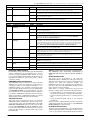
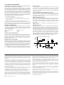
New Features
PC5200 Support
The PC5020 v3.1 and higher supports the new PC5200 Power Supply module. See PC5200 Power Supply Output
Module, Pg 2.
PC5936 Support
The PC5020 v3.1 and higher supports the PC5936 15-station audio matrix module. See PC5936 Audio Interface
Module, Pg 3.
SIA FAR
SIA False Alarm Reduction has been incorporated in this version. See the Quick Reference Chart SIA-FAR on the following page.
No Activity Arming
(by Partition)
This feature enables the system (or partition) to arm if there is no zone activity for a programmed time period. See
sections [191]-[198] - No-Activity Timer (Partition 1-8), Pg 30.
Programmable
Auto-arm Pre-Alert
Timer
The Auto- arm Pre-alert Time is now programmable. The default value for this timer has been extended to 5 minutes.
See Section [199] - Auto-arming Pre-Alert Time, Pg 30.
Periodic Test
Transmission
Exception
With this feature enabled, the panel will not send a test transmission if there has been any transmission received by
the receiver within the programmed time. See Section [018] - Sixth System Option Codes, Option 1, Pg 27.
Cross Zoning
This feature requires two or more trips on a zone(s) specified as “cross zones” within a specified time before starting
an alarm sequence. The Cross Zone option is programmable by zone via Attribute 9. See Section [018], Sixth System Option Codes,Option 6, Pg 28.
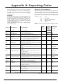
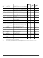
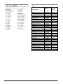
True Automatic
Contact ID
When selecting Automatic Contact ID for reporting, the reporting code will represent how a zone is defined according
to the SIA specification for Contact ID. If Automatic Contact ID is enabled, see Appendix A for reporting codes that
will be used for each zone type.
Keypad Buzzer
When enabled and the system or Partition is in alarm, all assigned keypad buzzers will follow the bell output. When
disabled, the keypad buzzers will only sound for buzzer type alarms. This option is off at default. See Section [018] Sixth System Option Codes, Option 5, Pg 28.
New Zone Types
See Sections [001]-[004] - Zone Definitions, Pg 21.
Zone Type 27 - Delayed 24 Hour Waterflow Zone
Zone Type 28 - Instant 24 Hour Waterflow Zone
Zone Type 29 - Auto Verified Fire Zone
Zone Type 30 - Fire Supervisory Zone
Zone Type 31 - Day Zone
Waterflow Silence
Inhibit Option
This option affects the Instant Waterflow Zone and the Delay Waterflow Zone.
This option does NOT allow the user to silence alarms, manually, automatically, or by a system reset until all waterflow
zones are returned to their restored state. See Section [018] - Sixth System Option Codes, Option 4, Pg 28.
Verbal Door Chime
and Verbal Alarm
Support
This feature enables the Door Chime to verbally annunciate the Zone that has been violated instead of a series of
beeps. See Section [018] - Sixth System Option Codes, Option 2&3, Pg 33. This feature is only available when using
the ESCORT5580 v3.0, and the PC5936 v1.0. Refer to the Escort5580 v3.0 and PC5936 v1.0 Installation Manuals
for further information.
Loop Response
The PC5020 v3.1 and higher can configure any or all onboard zones for 36 ms Loop Response (see Section [030] Fast Loop Response, Pg 29).
T-Link
The PC5020 v3.2 supports the T-Link TCP/IP Network Communicator.
i
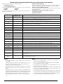
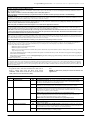
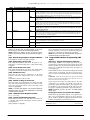
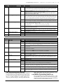
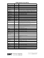
PC5020 Installer Programming Quick Reference Chart SIA False Alarm Reduction
Minimum requirement system for SIA-FAR Installations :
• 1 PC5020 Control panel
• 2 Local annunciation devices
The local annunciation devices may be any combination of the following keypads.
• LCD5500Z
• LCD5501Z
• PKP-LCD
• PKP-ICN
The following optional subassembly modules also bear the SIA FAR classification
and may be used if desired:
PC5108 Zone Expander Module
Compatible initiating devices: Bravo200 series, 300 series, 400 series, 500 series,
600 series, AC-100, Encore300 series, Force200 series, 210 series, MN240.
PC5208 Low Current PGM Output Module
The following optional accessory modules also bear the SIA FAR classification and
may be used if desired.
PC5204 Auxiliary Power Supply with PGM output ports
Escort5580/Escort5580TC
PC5400 Printer Module
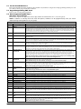
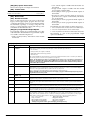
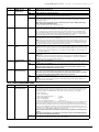
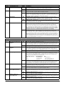
Section Number
Installation
Manual Section
Description
005
5.3
System Times: Access to Entry Delays and Exit Delay for each partition and Bell Time Out for the system.
009 – 011
5.3
Programmable Outputs: Access to PGM Output programming for the main board, PC5208 and PC5204 modules. Output
Attributes in Section in Sections 501 – 514. Partition Assignments in Section 551 – 564.
014, Option 6
5.3
Audible Exit Beeps: Enables beeps from the keypad for the duration of Exit Delay.
018, Option 6
5.3
Cross Zoning: This option enables Cross Zoning for the entire system. Individual zones can be enabled for Cross zoning
via Zone Attributes in Sections 101 – 164. Default = OFF
018, Option 7
5.3
Exit Delay Restart: Enables the Exit Delay Restart feature.
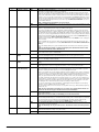
101 – 164
5.4
Zone Attributes: Access to zone attributes, such as, Audible Bell, Swinger Shutdown, Transmission Delay, and Cross Zone.
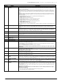
176
5.4
Cross Zone Timer: Access to the programmable Cross Zone timer.
304
5.6
Call Waiting Cancel Dialing String: Access to the Dialing sequence used to disable Call Waiting.
328, 6th Entry
5.6
Cross Zone Reporting Code: Access to the reporting code for Cross Zone Alarm.
328, 7th Entry
5.6
Burglary not Verified Reporting Code: Access to the reporting code for Burglary Not Verified.
328, 8th Entry
5.6
Alarm Cancelled Reporting Code: Access to the reporting code for Alarm Cancelled.
348, 1st and 2nd Entries
5.6
Walk Test End and Begin Reporting Codes: Access to the reporting codes for Walk Test Begin and Walk Test End.
377, 1st Entry
5.6
Swinger Shutdown for Alarms: Access to the Swinger Shutdown limit for zone alarms.
377, 4th Entry
5.6
Communications Delay: Access to the programmable delay before communicating alarms.
377, 11th Entry
5.6
Communications Cancel Window: Access to the programmable Communications Cancel window.
382, Option 2
5.6
Alarm Comms. During Walk Test: Enables Communication of zone alarms while installer Walk Test is active.
382, Option 3
5.6
Communications Cancelled Message: Enables the “Communications Cancelled” message display on all keypads.
382, Option 4
5.6
Call Waiting Cancel: Enables the use of the Call Waiting Cancel string in programmed in Section 304.
901
5.11
Installer Walk Test Mode: Enable/Disable Installer Walk Test mode. This mode can be used to test each zone on the system for proper functionality.
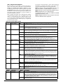
[*][5] Master Code
33rd and 34th Entries
4.1
Duress Code: Do not derive code from an existing Master/User code (eg., Master Code is 1234, the duress code should
not be 1233 or 1235.
[*][6] Master Code
Option 4
4.3
System Test: The system activates all keypad sounders, bells or sirens for 2 seconds and all keypad lights turn on. Refer
to the User Manual (part no. 29005909).
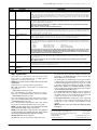
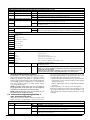
Notes
Caution
• For SIA FAR installations, only use modules / devices that are listed
on this page.
• Fire Alarm Verification feature (Auto Verified Fire zone) is not supported on 2-wire smoke detectors zones. This feature may be
enabled for 4-wire smoke detectors only.
• Call Waiting Cancel (Section 382 Option 4) feature on a non-Call
Waiting line will prevent successful communication to the central
station.
• All smoke detectors on the system must be tested annually by conducting the Installer Walk Test. Prior to exiting the walk test mode,
a sensor reset must be conducted on the system, [*][7][2] to reset
all latching 4-wire smoke detectors. Please refer to the smoke
detector installation instructions on how to correctly test the detectors.
ii
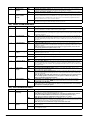
•
•
•
•
•
•
Programming at installation may be subordinate to other UL requirements for the intended application.
Cross zones have the ability to individually protect the intended area
(e.g., motion detectors, which overlap).
Cross zoning is not recommended for line security Installations nor is it to
be implemented on exit / entry zones.
There is a communication delay of 30 seconds in this control panel. It can
be removed, or it can be increased up to 45 seconds at the option of the
end user by consulting with the Installer.
Do not duplicate any reporting codes. This applies for all communication
formats other than SIA sending automatic programmed reporting codes.
The control unit must be installed with a local sounding device and an
off-premise transmission for SIA communication format.
Table of Contents
Commercial Burglary, Residential Fire and
Burglary Applications
Commercial Fire Applications
Section 1: Introduction
1
1.1 About the PC5020 System ........................................... 1
1.2 About the PC5020 Manual Set ..................................... 1
1.3
1.4
2.5
2.6
Current Ratings - Modules & Accessories ...................... 6
Assigning Zones to Zone Expanders .............................. 7
2.7
2.8
Keypad Assignment ...................................................... 7
Confirming Module Supervision ................................... 8
Section 3: How to Program
11
3.1 How to Enter Installer Programming ........................... 11
3.2 Programming Decimal Data ........................................ 11
3.5
Viewing Programming ................................................ 12
[*] Commands ........................................................... 14
Function Keys ............................................................. 17
4.4
4.5
Global and Partition Keypad Operation ....................... 18
Features Available for the LCD5500Z .......................... 18
Compatible Devices .................................................... 47
7.2
7.3
Fire Zones ................................................................... 49
Auto Verify Fire ........................................................... 49
7.4
7.5
Waterflow Zone .......................................................... 49
PC5700 Zones ............................................................ 50
7.6
7.7
Four-Wire Smoke Detector Zones ................................ 50
Two-Wire Smoke Detector Zones ................................ 50
7.8
Fire Supervisory Zone .................................................. 50
Section 8: Fire System Operation
51
8.1 Manual Signal Silence ................................................. 51
8.2 Automatic Signal Silence (Bell Time-out) ..................... 51
Section 4: Keypad Commands
13
4.1 Arming and Disarming ............................................... 13
4.2
4.3
Programmable Output Programming PWS Sect 8 ....... 42
International Programming PWS Sect 9 ....................... 43
Section 7: Fire Monitoring Zone Types
49
7.1 Partitions and Fire System Configuration ..................... 49
2.11 Keypad Zones ............................................................. 10
Programming Hexadecimal Data ................................. 11
Programming Toggle Options ..................................... 11
5.8
5.9
6.3
2.9 Removing Modules ....................................................... 8
2.10 Zone Wiring ................................................................. 8
3.3
3.4
Communicator Programming PWS Sect6 .................... 31
Downloading Options PWS Sect 7 .............................. 41
Section 6: Central & Remote Station Fire Installation
Instructions
47
6.1 Introduction ................................................................ 47
6.2 Hardware Description and Specifications ..................... 47
Section 2: Installation and Wiring
5
2.1 Installation Steps .......................................................... 5
2.2 Terminal Descriptions ................................................... 5
Wire Routing for Power & Non-Power Limited .............. 6
Keybus Operation and Wiring ....................................... 6
Partition & Zone Programming .................................... 30
5.6
5.7
5.10 Module Programming PWS Sect 10 ........................... 44
5.11 Special Installer Instructions PWS Sect 11 .................... 45
Main Panel Specifications ............................................. 1
Additional Devices ........................................................ 2
2.3
2.4
5.5
8.3
8.4
Manual Sensor Reset ([*][7][2]) ................................... 51
Subsequent Alarm Operation ...................................... 51
8.5
8.6
Auto-Scroll LCD Keypad Display .................................. 51
Fire Trouble Conditions ............................................... 51
8.7
8.8
AC Delays ................................................................... 52
Fire Reporting Codes .................................................. 52
Section 9: Listing Requirements
54
9.1 UL Listed Commercial and Residential Installations ...... 54
9.2 Commercial Fire Monitoring Installations ..................... 54
Section 5: Programming Sections
19
5.1 For the Record PWS Sect 1 ......................................... 20
5.2 Keypad Programming PWS Sect 2 .............................. 20
9.3
Appendix A: Reporting Codes
55
5.3
5.4
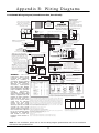
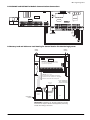
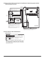
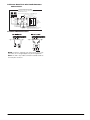
Appendix B: Wiring Diagrams
58
Basic Programming PWS Sect 3 .................................. 20
Advanced Programming PWS Sect 4 ........................... 29
iii
ULC Listing Requirements ........................................... 54
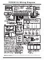
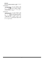
PC5020 UL Wiring Diagram
NOTE: For ULC installations please refer to the ULC Wiring Diagram part #18006238 and the ULC Installation Information Sheet part #29002157.
iv
Section 1: Introduction
1.1 About the PC5020 System
• Wireless expansion available using the PC5132 wireless 32 zone expansion module (433 or 900MHz, fully
supervised)
• Normally closed, Single EOL, or Double EOL zone
supervision
• 34 zone types, 8 programmable zone options
• Up to 8 partitions
Audible Alarm Output:
• 700mA supervised bell output (current limit 3 Amps),
12 VDC
• Steady or pulsed output
EEPROM Memory:
• Will not lose programming or system status on complete AC and battery failure
Programmable Outputs:
• Up to 14 programmable outputs, 21 programmable
options
• Three low current (50 mA) PGM outputs on main panel
(PGM1, PGM3, PGM4)
• One high current (300 mA) PGM output with 2-wire
smoke detector capability on main panel (PGM 2)
• Eight additional low current (50 mA) PGM outputs
available using the PC5208 module
• Four high current (1 Amp) PGM outputs available using
the PC5204 module (1 PC5204 output, fully supervised
for siren output)
Powerful 1.5 Amp Regulated Power Supply:
• 550 mA auxiliary supply, 12 VDC
• Positive temperature coefficient (PTC) components
replace fuses
• Supervision for loss of AC power, low battery
• Internal clock locked to AC power frequency
NOTE: For 24-hr standby, maximum Aux capacity is
420mA.
Power Requirements:
• Transformer = 16.0 VAC, 40VA (min) permanently
connected
• Battery = (2) 12 volt 7Ah (min.) rechargeable sealed lead
acid
or (1) 12 volt 4Ah battery (for Burglary applications only)
• PC5020 current draw: 65mA
Remote Keypad Specifications:
• Various keypads are available:
- PC5508Z 8 Zone LED keypad
- PC5516Z 16 Zone LED keypad
- PC5532Z 32 Zone LED keypad
- LCD5500Z Liquid Crystal Display keypad
- LCD5501Z LCD-style keypad
- LCD5501Z32-900/LCD5501Z32-433 keypad/receiver
• ’Z’ version keypads have one zone input
• Each keypad has 5 fully programmable function keys
• Connect up to 8 keypads
• Four wire (Quad) connection to Keybus
• Built in piezoelectric buzzer
Digital Communicator Specifications:
• Supports all major formats including SIA, Contact ID,
and Residential Dial
• Split reporting of selected transmissions to each telephone number
• 3 programmable telephone numbers
The PC5020 is a high end security system. It supports up
to 64 zones, 8 separate partitions, and 32 users.
The user interface is simple and easy to use. The
LCD5500Z keypad guides users through their available
options with easy-to-understand prompts.
The status of the PC5020 system can be monitored over
telephone lines, or using an alternative communicating
device, including LINKS1000, LINKS2X50, LINKS3000,
Skyroute™ and DVACS*.
The PC5020 main board comes with 4 programmable outputs, and you can add up to 12 more using PC5204 and
PC5208 modules. You can program the outputs to control
things such as doorstrikes and lights, using 25 different
output options. See ‘Programmable Outputs’ in Section 5.
You can program the PC5020 using any system keypad,
or using DLS-3 downloading software and a computer.
See ‘How to Program’ on page 10.
Review the complete PC5020 manual set before installing
the PC5020 security system
1.2 About the PC5020 Manual Set
Installer Manuals
Read the entire manual carefully before beginning your
installation.
This manual describes:
• An overview of the system (Section 1: ’Introduction’)
• How to install and wire the system and its modules
(Section 2: ’Installation and Wiring’)
• How to program the system (Section 3: ’How to Program’)
• An introduction to the user interface and keypad operation (Section 4: ’Keypad Commands’)
• An overview of the main system programming sections (Section 5: ’Programming Sections’).
Be sure to record all your system programming in the Programming Worksheets.
If you will be adding modules to your PC5020 system, read
the Installation Instructions that come with each module.
User’s Guide
One User’s Guide comes with the PC5020 system. The
User’s Guide provides easy to follow instructions for endusers. Installers should also review this manual, in order
to properly instruct the end-users once the installation is
complete.
Commercial Fire Application
Please refer to the Central and Remote Station Fire Installation Guide for information concerning Commercial Fire
applications.
1.3 Main Panel Specifications
Flexible Zone Configuration:
• 8 fully programmable zones
• 39 access codes: 32 user, 1 system master, 2 supervisor
codes, 2 duress, 1 maintenance and 1 installer code
• Expandable to 64 zones
• Keypads with zone inputs available (PC5508Z,
PC5516Z, PC5532Z, LCD5500Z, and LCD5501Z)
• Hardwired expansion available using the PC5108 8zone expansion module, the PC5100 addressable 32
zone expansion module and the PC5700/5720 fire
module
*DVACS is a registered trademark of Electro Arts Limited.
1
• 1 system account number, plus 8 partition account
numbers
• Supports LINKS1000, GSM1000 cellular communication, Links 2X50 long range alarm transmitter and Skyroute™ Cellemetry communication transceiver
• DTMF and pulse dialing
• DPDT line seizure
• Anti-jam detection
• Event-initiated personal paging
• T-Link communications via PC-Link (see T-Link Installation Manual part no. 29001007)
System Supervision Features
The PC5020 continuously monitors a number of possible
Trouble conditions including:
• AC power failure
• Trouble by zone
• Fire trouble
• Telephone line trouble
• Low battery condition
• Bell output trouble
• Loss of internal clock
• AUX power supply fault
• Tamper by zone
• Failure to communicate
• Module Fault (Supervisory or Tamper)
• Camera Troubles via DLM-4L
False Alarm Prevention Features
• Audible Exit Delay
• Audible Exit Fault
• Urgency on Entry Delay
• Quick Exit
• Swinger Shutdown
• Recent Closing Transmission
• Cross Zone Alarm
• Burglary-verified timer
• Double Hit Timer
• Communication Delay
• Rotating Keypress Buffer
Additional Features
• Automatic arming by partition at a specified time, each
day of the week
• Keypad-activated alarm output and communicator test
• Keypad lockout
• Audio capability using the PC5936 audio interface module; allows local intercom and central station 2-way listen-in
• All modules connect to the system via a four wire Keybus, up to 1000’/305m from the main panel
• Event buffer can be printed using PC5400 RS-232 serial
interface module
• Supports the Escort5580(TC) Voice Prompt Module,
with automation and lighting control
• 256-event buffer, time and date stamped
• Uploading/downloading capability
• Daylight Savings Time option
• Downlook support (DLM-4L v1.0 and PC5108L)
• PC5508Z: 8 zone LED keypad, with one zone input
• PC5516Z: 16 zone LED keypad, with one zone input
• PC5532Z: 32 zone LED keypad, with one zone input
• LCD5500Z: LCD keypad, with one zone input
• LCD5501Z: LCD-style keypad, with one zone input
• LCD5501Z32-433: keypad/receiver
NOTE: The following keypad versions can only be used
on the first two partitions (partition 1 and partition 2),
and the first 8, 16, or 32 zones: PC5508(Z), PC5516(Z),
PC5532(Z) v2.00 and lower, LCD5500(Z) versions 2.x and
lower, LCD5501Z versions 1.x and lower
PC5100 2-Wire Addressable Device Interface Module
The PC5100 module is used to connect 2-wire addressable
devices to the system. Up to 32 2-wire addressable devices
can be added to the system.
NOTE: PC5100 v1.0 and lower modules can only support the first 32 zones on the PC5020 system.
PC5108 Eight Zone Expander Module
Eight zone expander module can be used to increase the
number of zones on the system. Up to 7 modules can be
connected to increase the system zones to a maximum of
64 (see the PC5108 Installation Instructions Sheet).
NOTE: PC5108 v1.0 and lower modules can only support
the first 32 zones on the PC5020 system. PC5108 v1.0 and
lower modules enroll as two modules and use up two
supervisory slots.
NOTE: Do not mix PC5108 v1.x and lower modules with
PC5108 v2.0 and higher modules on the same system.
PC5132 Wireless Receiver Module
The PC5132 wireless receiver module can be used to connect up to 32 fully supervised wireless devices (see the
PC5132 Installation Manual for details.)
NOTE: Only the first 32 zones on the PC5020 system can
be used as wireless zones.
PC5200 Power Supply Output Module
The PC5200 can provide up to 1 Amp of additional power
for modules or devices connected to the control panel. Up
to 4 modules can be connected to the system. Each module
requires a 16.5 volt AC 40 VA transformer and 4Ah battery
(see PC5200 Installation Instructions for details).
PC5204 Power Supply Output Module
The PC5204 can provide up to 1 Amp of additional power
for modules or devices connected to the control panel. The
module requires a 16.5 volt AC 40 VA transformer and 4
Ah battery. In addition, the module provides 4 programmable high current voltage outputs. (See PC5204 Installation Instructions for details).
PC5208 Eight Low Current Output Module
Adds 8 programmable low current outputs (50mA) to the
control (see the PC5208 Installation Instructions for details).
NOTE: If you use the main panel and the PC5208 outputs, PGM 3 will work the same as the first PC5208 output, and PGM 4 will work the same as the second
PC5208 output.
Escort5580(TC) Module
This Escort5580(TC) module will turn any tone telephone
into a fully functional keypad. The module also includes a
built-in interface to control up to 32 line carrier type
devices for lighting and temperature control (see the
Escort5580(TC) Installation Manual for details.)
NOTE: Users will not be able to access partitions 3 to 8,
and zones 33 to 64 through Escort5580(TC) versions 2.x
and lower. Only partitions 1 and 2, and zones 1 to 32
are supported on these versions.
1.4 Additional Devices
In addition to the information below, see the back cover for
a DSC Module Compatibility table.
Keypads
A maximum of 8 keypads can be connected to the control
panel. You can connect any combination of the following
listed. Different keypads (with function keys) can be used
for different size systems: 8 zone, 16 zone, 32 zone, & 64
zone.
2
Introduction: 1.4 Additional Devices
PC5936 Audio Interface Module
The PC5936 audio interface module provides paging,
intercom, baby listen-in and door answer to the PC5020
control panel. The module has built-in two-way voice
capability for central station (see the PC5936 Installation
Manual for details).
Three additional devices are available:
• PC5921 PKP-ICM Intercom Audio Station can be used in
conjunction with the PC5936 Audio Interface Module.
• PC5921 EXT Door Box Audio Station can be used in
conjunction with the PC5936 Audio Interface Module.
• PC5921 EXT/R Door Box Audio Station can be used in
conjunction with the PC5936 Audio Interface Module.
The Door Box contains a relay so the normal door bell
can be used instead of the internal one generated by the
PC5936 Audio Interface Modules.
PC5400 Printer Module
This PC5400 printer module will allow the panel to print
out all events that occur on the system to any serial
printer. All events will be printed with the partition, time,
date and the event that occurred (see PC5400 Installation
Manual for details).
NOTE: The PC5400 v2.x and lower only supports
events on partitions 1 and 2, and zones 1-32.
LINKS1000 Cellular Communicator
The LINKS1000 Cellular Communicator provides an efficient, cost-effective method for adding cellular back-up.
The unit comes in its own cabinet with antenna and
requires a separate battery and transformer (see Links1000
Cellular Communicator in Section 5).
T-Link Local Area Network Communicator
The T-Link Local Area Network Communicator provides
an efficient method of communicating via a Local Area
Network (LAN). See the T-Link Installation Manual for
more details.
Alternate Communicators
Refer to the associated Installation Manual for LINKS2X50,
LINKS3000, & Skyroute™ programming details.
Downlook Support: PC5108L and DLM-4 v1.0L
The PC5108L will expand the control panel’s zone capability by adding eight fully programmable zone inputs.
The module will also act as an interface between the
DLM-4L v1.0 video transmission module and the PC5020
control panel. The PC5108L is also an 8-camera video
switcher.
For more information on either module, see their respective
Installation Manuals.
NOTE: The PC5108L module can only be assigned zones
from 9 to 32. The PC5108L will not support zones 33 to
64. Camera scripts can only be run for zones 1 to 32. The
PC5108L enrolls as two expander modules and use up
two supervisory slots.
NOTE: Do not mix PC5108L v1.x and lower modules with
PC5108 v2.0 and higher modules on the same system.
PC5700 Fire Module
This is a zone expansion module with four general purpose zone inputs, two Class A supervisory waterflow
zone inputs, ground fault detection and dual-supervised
telephone line inputs.
PC5720 Fire Module
This is a zone expansion fire module that can be used for
ULC Listed non-residential fire applications. The PC5720
can also be used as an interface between the control panel
and either a serial printer or a DVACS communications
network.
NOTE: The PC5700 v1.x and PC5720 v1.x enroll as two
expander modules and use two supervisory slots.
NOTE: Do not mix PC5700 v1.x and PC5720 v1.x and
lower modules with PC5108 v2.0 and higher modules
on the same system.
Cabinets
Several different cabinets are available for the PC5020
modules. They are as follows:
• PC4050C - alternate main control cabinet (Household
Fire & Burglary) for the PC5020 main panel. Dimensions 305mm x 376mm x 125mm / 12.0” x 14.8” x 4.9”
approximately.
• PC4050CR - alternate main control cabinet (Commercial Fire) for the PC5020 main panel. Dimensions
305mm x 376mm x 125mm / 12.0” x 14.8” x 4.9”
approximately.
• PC4050CAR - alternate main control cabinet (Commercial Burglary) for the PC5020 main panel. Dimensions 305mm x 376mm x 125mm / 12.0” x 14.8” x 4.9”
approximately.
• PC4050CRAR - alternate main control cabinet (Commercial Fire and Commercial Burglary) for the PC5020
main panel. Dimensions 305mm x 376mm x 125mm /
12.0” x 14.8” x 4.9” approximately.
• PC500C - alternate main control cabinet (Household
Burglary). Dimensions 213mm x 235mm x 78mm / 8.4”
x 9.25” x 3” approximately.
• PC5002C - cabinet to house the PC5204 power supply
output module. Dimensions 213mm x 235mm x 78mm
/ 8.4” x 9.25” x 3” approximately.
• PC5003C - main control cabinet for the PC5020 main
panel. Dimensions 222mm x 298mm x 78mm / 11.3” x
11.7” x 3.0” approximately (Household Fire & Burglary).
• PC5004C - cabinet to house the Escort5580(TC) module
and PC5400 Printer Module. Dimensions 229mm x
178mm x 65mm / 9” x 7” x 2.6” approximately.
• PC5001C - cabinet to house the PC5108 zone expander
module and the PC5208 8 low current output module.
Dimensions 153mm x 122mm x 38mm / 6” x 4.8” x
1.5” approximately.
• PC5001CP - plastic cabinet to house the PC5108 zone
expander module and the PC5208 8 low current output
module. Dimensions 146mm x 105mm x 25.5mm /
5.75” x 4.2” x 1” approximately.
• CMC-1 - alternate main control cabinet (Commercial
Burglary) Dimensions 222mm x 298mm x 78mm / 11.3”
x 11.7” x 3.0” approximately.
• Multi-3 - cabinet to house the PC5936/PC5937 modules. Dimensions 287mm x 298mm x 78mm / 11.3” x
11.7” x 3.0” approximately.
• HS-CAB100 - structured wiring cabinet for PC5020
main panel. Dimensions 362mm x 229mm x 102mm /
14.25” x 9” x 4” with a wire raceway positioned on the
right side of the cabinet. The cover is 389mm x 254mm
/ 15.3” x 10”.
• HS-CAB200 - structured wiring cabinet for PC5020 main
panel. Dimensions are 362mm x 362mm x 102mm /
14.25” x 14.25” x 4” with a wire raceway in the center of
the cabinet. The cover is 389mm x 389mm / 15.3” x 15.3”.
• HS-CAB2800 - structured wiring cabinet for PC5020
main panel. Dimensions 724mm x 362mm x 102mm /
28.5” x 14.25” x 4” with a wire raceway in the center of
the cabinet. The cover is 752mm x 387mm / 29.6” x
15.3”.
• HS-CAB4200 - structured wiring cabinet for PC5020
main panel. Dimensions 1086mm x 362mm x 102mm /
42.75” x 14.25” x 4.0” with a wire raceway in the center
of the cabinet.
3
Backplates
There are two different backplates available for keypads
to mount an audio station next to a keypad:
PC55BP1 Backplate
Use this backplate when
mounting an audio station next
to a keypad. Dimensions
208mm x 115mm x 18mm /
8.2” x 4.5” x 0.25” approximately.
PC55BP2 Backplate
Use this backplate when
mounting an audio station
next to a keypad. In addition
the backplate will allow you
to mount a PC5108 zone
expander module or the
PC5208 8 low current output
module. Dimensions 208mm x 115mm x 18mm / 8.2” x
4.5” x 0.7” approximately.
4
Section 2: Installation and Wiring
The following sections provide a complete description of how to wire and configure devices and zones.
2.1 Installation Steps
Step 10 Programming the System (Sections 4 & 5)
Section 4.0 provides a complete description of how to program the panel. Section 5.0 contains complete descriptions
of the various programmable features, what options are
available and how the options function. The Programming
Worksheets should be filled out completely before attempting
to program the system.
Step 11 Testing the System
Test the panel completely to ensure that all features and
functions are operating as programmed.
The following steps are provided to assist with the installation of the panel. It is suggested that you read over this
section briefly to get an overall understanding of the
order of installation. Once this is done carefully work
through each step. Working from this plan will help
reduce problems and reduce the overall installation time
required.
Step 1 Create a Layout
Draw a rough sketch of the building and include all alarm
detection devices, zone expanders, keypads and all other
modules that are required.
Step 2 Mounting the Panel
Locate the panel in a dry area, preferably located near an
unswitched AC power source and the incoming telephone line. Before attaching the cabinet to the wall be
sure to press the five circuit board mounting studs into
the cabinet from the back.
NOTE: Complete all wiring before applying AC or connecting the battery.
Step 3 Wiring the Keybus (Section 2.4)
Wire the Keybus to each of the modules following the
guidelines provided.
Step 4 Assigning Zones to Zone Expanders
(Section 2.6)
If zone expander modules are being used the modules
must be configured so the panel knows which zones are
assigned to each expander. Follow the guideline provided
to assign zones to expanders.
Step 5 Zone Wiring (Section 2.10)
Power down the control panel and complete all zone wiring. Follow the guidelines provided in section 2.10 to connect zones using normally closed loops, single EOL
resistor, double EOL resistors, Fire zones and Keyswitch
Arming zones.
Step 6 Completing Wiring
Complete all other wiring including bells or sirens, telephone line connections, ground connections or any other
wiring necessary. Follow the guidelines provided in section 2.2 ‘Terminal Descriptions’.
Step 7 Power up the Control Panel
Once all zone wiring and Keybus wiring is complete,
power up the control panel.
NOTE: The panel will not power up if only the battery
is connected.
Step 8 Keypad Assignment (Section 2.7)
Keypads must be assigned to different slots to be properly supervised. Follow the guideline provided in section
2.7 to assign keypads.
Step 9 Confirming Module Supervision
(Section 2.8)
By default, all modules are supervised upon installation.
Supervision is enabled at all times so that the panel can
indicate a Trouble if a module is removed from the system.
To confirm that each module is properly supervised, follow the guidelines provided in section 2.8.
2.2 Terminal Descriptions
AC Terminals
The panel requires a 16.5 volt, 40 VA transformer. Connect the transformer to an unswitched AC source and
connect the transformer to these terminals.
NOTE: Do not connect the transformer until all other
wiring is complete.
Battery Connection
The battery is used to provide backup power in the event
of an AC power failure and to provide additional current
when the panel demands exceed the power output of the
transformer, such as when the panel is in alarm.
NOTE: Do not connect the battery until all other wiring is complete.
Connect the RED battery lead to the positive of the battery, the BLACK battery lead to the negative.
Auxiliary Power Terminals - AUX+ and GND
These terminals provide up to 550mA of current at 12
VDC (rated 11.6-12.6 VDC for UL residential applications) for devices requiring power. Connect the positive
side of any device requiring power to the AUX+ terminal,
the negative side to GND. The AUX output is protected; if
too much current is drawn from these terminals (wiring
short) the panel will temporarily shut off the output, until
the problem is corrected. NOTE: The maximum AUX
capacity for 24-hr standby is 420mA.
Bell Output Terminals - BELL+ and BELLThese terminals provide up to 3 Amps of current at 12 VDC
(with standby battery; 700 mA continuous) for powering
bells, sirens, strobes or other warning type equipment.
Connect the positive side of any alarm warning device to
BELL+, the negative side to BELL–. The BELL output is
protected; if too much current is drawn from these terminals (wiring short) the BELL PTC will open.
The bell output is supervised. If no alarm warning device
is being used connect a 1KΩ resistor across BELL+ and
BELL– to prevent the panel from displaying a Trouble condition (see section ’[*][2] Trouble Display’).
Keybus Terminals - RED, BLK, YEL, GRN
The Keybus is used by the panel to communicate with
modules and by modules to communicate with the panel.
Each module has four Keybus terminals that must be connected to the four Keybus terminals on the panel. For
more information, see section ’Keybus Operation and
Wiring’.
5
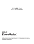
Programmable Outputs PGM1, PGM2, PGM3, PGM4
Each PGM output is designed so
that when activated by the panel,
the terminal will switch to ground
PGM1, PGM3, and PGM4 can
each sink up to 50 mA of current.
These PGMs can be used to activate LEDs or a small buzzer. Connect the positive side of the LED
or buzzer to AUX+, the negative
side to the PGM.
PGM2 is a high current output
(300mA) and operates similarly to
PGM1. If more than 300 mA of current is required, a relay must be used. PGM2 can be used
for 2-wire smoke detectors with Jumper CON1 removed,
otherwise, CON1 must remain on at all times (see section
2.10 ‘Zone Wiring‘).
Zone Input Terminals - Z1 to Z8
Each detection device must be connected to a zone on the
control panel. It is suggested that each zone have one
detection device however it is possible to wire multiple
detection devices to the same zone.
For zone wiring specifics, see section ’Zone Wiring’.
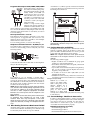
Telephone Connection Terminals - TIP, RING, T-1, R-1
If a telephone line is required for central station communication or downloading, connect an RJ-31X jack in the
following manner:
A minimum ¼” (6.4mm) separation must be maintained
at all points between power limited and non-power limited wiring and connections.
Keybus
NOTE: A minimum 1/4" (6.4mm) separation
must be maintained at all points between
power limited and non-power limited wiring
and connections.
NOTE: Wire entry for power limited wiring must be
separated by a different entry access from non-power
limited wiring.
2.4 Keybus Operation and Wiring
The Keybus is used by the panel to communicate with all
modules connected and by the modules to talk to the
panel. The RED and BLK terminals are used to provide
power while YEL and GRN are clock and data.
NOTE: The 4 Keybus terminals of the panel must be
connected to the 4 Keybus terminals or wires of all
modules.
The following conditions apply:
• Keybus should be run in minimum 22 gauge quad
(0.5mm), two pair twisted preferred
• the modules can be home-run to the panel, connected in
series or can be T-tapped
• any module can be connected anywhere along the Keybus; you do not need a separate Keybus wire run for
keypads, zone expanders etc.
• no module can be more than 1,000'/305m (in wire
length) from the panel
• shielded wire is not necessary unless wires are run in an
area that may present excessive RF noise or interference
Connect the PC5020 and modules that use the telephone
line(s) in the following order:
PC5936
For example, if you are installing a PC5020 with a
LINKS1000/GSM1000 and a PC5936 intercom module,
connect the incoming line to the LINKS1000, then from
the LINKS1000 to the PC5020, then from the PC5020 to
the PC5936 audio module and then from the PC5936
module to the house telephones.
NOTE: Ensure that all plugs and jacks meet the dimension, tolerance and metallic plating requirements of 47
C.F.R. Part 68, SubPart F. For proper operation there
must be no other telephone equipment connected
between the control panel and the telephone company facilities.
NOTE: Do not connect the alarm panel communicator
to telephone lines intended for use with a FAX
machine. These lines may incorporate a voice filter
which disconnects the line if anything other than FAX
signals are detected, resulting in incomplete transmissions.
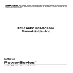
Example of Keybus Wiring
Module (A) is wired correctly as it is within 1,000'/
305m of the panel, in wire
distance. Module (B) is
wired correctly as it is
within 1,000'/305m of the
panel, in wire distance.
Module (C) is NOT wired
correctly as it is further than 1,000'/305m from the panel,
in wire distance.
2.5 Current Ratings - Modules & Accessories
In order for the PC5020 system to operate properly, the
power output capabilities of the main control and expansion devices must not be exceeded. Use the data presented below to ensure that no part of the system is
overloaded and cannot function properly.
PC5020 Device Ratings (@ 12 VDC)
• LCD5500Z Keypad: 85 mA
• LCD5501Z Keypad: 45mA
• LCD5501Z32-433 Keypad/Receiver: 260mA (max.)
2.3 Wire Routing for Power & Non-Power Limited
All wiring entry points are designated by the arrows. All
circuits are classified UL installation power limited except
for the battery leads which are not power limited.
6
Installation and Wiring: 2.6 Assigning Zones to Zone Expanders
NOTE: Before a zone expander will work properly, you
must set the jumpers so the panel can determine the
correct zone assignment.
NOTE: It is not recommended to use PC5108 v1.x and
v2.x simultaneously on the same PC5020.
The following are the jumper settings for different zone
assignments for PC5108 v2.0 modules. If you need to
enroll PC5108 v1.0, PC5108L or PC5700 modules, refer to
the appropriate module Installation Sheet for the correct
jumper settings.
• PC5100 Addressable Device Interface Module: 40mA
• PC5508Z Keypad: 80 mA
• PC5516Z Keypad: 90 mA
• PC5532Z Keypad: 120 mA
• PC5108 Zone Module: 35 mA
• PC5108L Downlook Interface: 60 mA
• PC5132 Wireless Module: 125 mA
• PC5200 Output Module: 20 mA
• PC5204 Output Module: 20 mA
• PC5208 Output Module: 50 mA
• PC5320 Multiple Receiver Interface Module: 55mA
• Escort5580(TC) Module: 150 mA
• PC5400 Printer Module: 65 mA
• PC5700 Fire Module: 150 mA
• PC5904 Central Station Talk/Listen Module: 175mA
• PC5936 Audio Interface Module: 65 mA
• PC5937 Audio Port Expansion Module: 5mA
• PC5921 Intercom Audio Station: 20 mA
• PC5921 EXT Door Box Audio Station: 20 mA
• PC5921 EXT/R Door Box Audio Station: 35 mA
• DLM-4L v1.0: 180 mA
• T-Link module: 150mA
System Outputs (all 12 VDC)
PC5020
VAUX:
BELL:
PC5200
PC5204
VAUX:
VAUX:
PC5208
VAUX:
PC5108
VAUX:
550 mA.
Subtract the listed rating for each keypad, expansion module and accessory connected to VAUX or
Keybus. NOTE: The maximum AUX capacity
for 24-hr standby is 420mA.
700 mA.
Continuous Rating.
3.0 A.
Short Term. Available only with standby battery
connected.
1.0 A.
Continuous Rating. Subtract for each device connected.
3.0 A.
Short Term. Available only with standby battery
connected.
1.0 A.
Continuous Rating. Subtract for each device connected.
3.0 A.
Short Term. Available only with standby battery
connected.
250 mA.
Subtract for each device connected. Subtract the
total load on this terminal from the PC5020
VAUX/Keybus output.
100 mA.
Subtract for each device connected. Subtract the
total load on this terminal from the PC5020
VAUX/Keybus output.
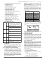
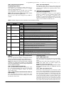
Module Jumpers
J1
J2
System Zones
Assigned
J3
ON
ON
ON
OFF
ON
ON
Zones disabled
Zones 09 - 16
ON
OFF
ON
Zones 17 - 24
OFF
OFF
ON
Zones 25 - 32
ON
ON
OFF
Zones 33 - 40
OFF
ON
OFF
Zones 41 - 48
ON
OFF
OFF
Zones 49 - 56
OFF
OFF
OFF
Zones 57 - 64
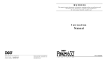
The following is a diagram of the PC5108 zone expander
modules and where the jumper switches are located. Refer
to the Installation Instructions for the module for more information.
NOTE: Only jumpers J1, J2, and J3 determine the zone
assignment for the module.
2.7 Keypad Assignment
There are 8 available slots for keypads. LED and
LCD5501Z keypads by default are assigned to slot 1. The
LCD5500Z is assigned by default to slot 8. Keypads can
each be assigned to a different slot (1 to 8) which offers
two advantages. The panel can supervise the keypad connection to indicate a Trouble condition if it is removed.
Also keypads can be assigned to operate a specific partition, or to operate as a global keypad.
How to Assign Keypads
NOTE: All keypad assignment must be done at each
keypad on the system. When using LCD5500(Z) keypads, one keypad must remain in slot 8. Do not assign
more than one keypad to the same slot.
NOTE: The following keypad versions can only be used
on partition 1 & partition 2, and the first 8, 16, or 32
zones: PC5508(Z), PC5516(Z), PC5532(Z) versions v2.0 &
lower, LCD5500(Z) versions 3.x and lower. To assign a
keypad to a slot and select the partition it will operate,
enter the following:
1. Enter Installer Programming
2. Press [000] for Keypad Programming
3. Press [0] for Partition and Slot Assignment
4. Enter a two digit number to specify the partition and slot
assignment.
1st digit enter 0 for Global operation, or
enter 1-8 for partitions 1-8
2nd digit enter 1 to 8 for Slot Assignment
5. Press the [#] key twice to exit programming.
Other Devices
Read the manufacturer’s literature carefully to determine
the maximum current requirement (during activation or
alarm) and use this value for loading calculations. Do not
allow connected devices to exceed the system capabilities
during any possible operational mode.
2.6 Assigning Zones to Zone Expanders
The main panel contains zones 1 to 8. Additional zone
expanders may be added to increase the number of zones
on the system. Each zone expander consists of one group
of 8 zones. Each module must be set to assign the specific
zones to the expander. To do this, set the jumpers located
on the expander to the proper settings (see chart below).
NOTE: PC5108 v1.0 and lower modules can only support the first 32 zones on the PC5020 system. PC5108
v1.0 and lower, PC5108L, PC5700, and PC5720 each
enroll as two expander modules.
7
6. Continue this procedure at each keypad until all have
been assigned to the correct slot and partition.
How to Program Function Keys
Each of the 5 function keys on each keypad may be programmed for different operation.
1. Enter Installer Programming.
2. Press [000] for Keypad Programming.
3. Enter [1] to [5] to select function key to program.
4. Enter a 2-digit number for function key option - [00] to [30].
5. Continue from step 3 until all function keys are programmed.
6. Press [#] key twice to exit Installer Programming.
For a complete list of Function Key options, see section
’Function Keys’.
2.8 Confirming Module Supervision
By default, all modules are supervised upon installation.
Supervision is enabled at all times so that the panel can
indicate a trouble if a module is removed from the system.
To check which modules are currently connected and
supervised:
1. Press [*] [8] [Installer Code] to enter Installer Programming.
2. Press [903] to display all modules.
3. The LCD keypad will allow you to scroll through the
modules.
NOTE: Module supervision will not display correctly at
an LCD5500Z v2.x and lower keypad.
In LED keypads, zone lights will be turned on according
to what modules the panel has found on the system.
Refer to the following chart:
Keypad Light
Module/Device Present
[1]
[2]
[3]
[4]
[5]
[6]
[7]
[8]
[9]
[10]
[11]
[12]
[13]
[14]
[15]
[16]
[17]
[18]
[19]
[20]
[21]
[22]
[23]
[24]
[25]
[26]
[27]
[28]
[29]
Keypad 1
Keypad 2
Keypad 3
Keypad 4
Keypad 5
Keypad 6
Keypad 7
Keypad 8
Zones 9 to 16
Zones 17 to 24
Zones 25 to 32
Zones 33 to 40
Zones 41 to 48
Zones 49 to 56
PC5100
Zones 57 to 64
PC5132
PC5208
PC5204
PC5400
PC5936
LINKS2X50/Skyroute™
DLM-4L v1.0
Escort5580(TC)
Future Use
PC520X-1
PC520X-2
PC520X-3
PC520X-4
If a module is connected but does not show as being
present, it may be due to any of the following reasons:
• it is not connected to the Keybus
• there is a Keybus wiring problem
• the module is more than 1,000'/305m from the panel
• the module does not have enough power
• the PC5132 does not have any devices added
2.9 Removing Modules
If a module is no longer required on the system, the panel
must be told to stop supervising the module. To do this:
1. Remove the module from the Keybus.
2. Press [*] [8] [Installer Code] to enter Installer Programming.
3. Press [902] to enable supervision. The panel will automatically search for all modules on the system, will see
that the module has been removed, and will stop supervising it.
4. Once the search is complete (it will take about 1 minute)
enter section [903] to confirm that the correct modules
are supervised on the system.
2.10 Zone Wiring
For a complete description of the operation of all zone
types, see section ’Basic Programming PWS Sect 3’.
There are several different ways in which zones may be
wired, depending on which programming options have
been selected. The panel can be programmed to supervise
normally closed, end of line, or double end of line loops.
Refer to the following sections to study each type of individually supervised zone wiring.
NOTE: Any zone programmed for Fire or 24-hr Supervisory must be wired with a single end of line (EOL)
resistor regardless of the type of zone wiring supervision selected for the panel (section [013], options [1]
and [2]). See Zone Definitions [001] [004]. If you
change the zone supervision options from DEOL to
EOL or from NC to DEOL (section [013], options [1] or
[2]), power the system down completely, and then
power it back up for correct operation.
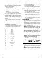
Normally Closed (NC) Loops
To enable normally closed loops, programming section
[013], option [1] must be ON.
NOTE: This option should only be selected if Normally
Closed (NC) devices/contacts are being used.
ANY Z
ANY COM
TERMINAL TERMINAL
ANY Z
ANY COM
TERMINAL TERMINAL
Normally Closed Loops. . . . . . . . . . . . . . . Section [013], Option [1]
Single End Of Line (EOL) Resistors
To enable panel detection of single end of line resistors,
programming section [013], options [1] and [2] must be
OFF.
NOTE: This option should be selected if either Normally Closed (NC) or Normally Open (NO) detection
devices or contacts are being used.
8
Installation and Wiring: 2.10 Zone Wiring
For a complete description of how fire zones operate, see
section ’Basic Programming PWS Sect 3’.
Fire Zone Wiring - 2-wire Smoke Detectors
If PGM2 has been programmed for 2-wire smoke detector
connection (see section ’Basic Programming PWS Sect 3’),
the detectors must be wired according to the following
diagram:
End of Line Resistors . . . . . . . . . . . . . . . . Section [013], Option [1]
Single End of Line Resistors . . . . . . . . . . . Section [013], Option [2]
NOTE: If PGM2 is programmed for 2-wire smoke support, Jumper CON1 on the main board must be
removed.
For a complete description of how fire zones operate, see
section ’Basic Programming PWS Sect 3’.
Keyswitch Zone Wiring
Zones may be programmed to be used as keyswitch arming zones and must be wired according to the following
diagram:
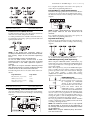
Double End of Line (DEOL) Resistors
Double end of line resistors allow the panel to determine
if the zone is in alarm, tampered or faulted.
To enable panel detection of double end-of-line resistors,
programming section [013], option [1] must be OFF and
option [2] must be ON.
NOTE: If the double EOL supervision option is
enabled, all hardwired zones must be wired for double
EOL resistors, except for Fire and 24-hr Supervisory
zones.
Do not wire DEOL resistors on keypad zones.
Do not use DEOL resistors for Fire zones or 24-hr
Supervisory zones. Do not wire Fire zones to keypad
zone terminals if the DEOL supervision option is
selected.
This option can only be selected if Normally Closed
(NC) detection devices or contacts are being used. Only
one NC contact can be connected to each zone.
The following chart shows zone status under certain conditions:
Loop Resistance
Loop Status
0Ω (shorted wire, loop shorted)
Fault
5600Ω (contact closed)
Secure
Infinite (broken wire, loop open)
Tamper
11200Ω (contact open)
Violated
For a complete description of how keyswitch zones operate, see section ’Basic Programming PWS Sect 3’.
LINKS1000 Supervisory (24-hr Supervisory)
When using the LINKS1000 cellular communicator, any
main board zone may be configured for LINKS1000 Supervision. Program this zone as zone type (09), 24-hr Supervisory in section [001].
With a 24-hr Supervisory zone, if the LINKS1000 experiences a trouble, the zone will be violated, causing the
panel to report the event to the central station. This type
of zone always requires a single EOL resistor
(5600Ω).Refer to LINKS 1000 Installation Manual wiring
diagram for installation.
LINKS1000 Answer
If the LINKS1000 cellular communicator is being used a zone may
be configured for LINKS1000
Answer to allow downloading to
be performed in the event of telephone line failure. When the
LINKS1000 receives a telephone
call it will activate the RING terminal on the LINKS1000 circuit board. This terminal can be
used to violate a zone programmed as (24) LINKS1000
Answer (see section ’Basic Programming PWS Sect 3’),
causing the panel to seize the telephone line and begin
communication with the downloading computer.
The zone programmed as LINKS1000 Answer ALWAYS
requires a single EOL resistor (5600Ω) and must be wired
according to the diagram above.
NOTE: The LINKS1000 Answer zone is only required
for downloading to the panel via the LINKS1000, or
for remotely connecting to the Escort5580(TC) module
via the LINKS1000.
NOTE: When using the LINKS1000, Busy Tone Detection must not be used.
End-of-Line Resistors . . . . . . . . . . . . . . . . Section [013], Option [1]
Double End-of-Line Resistors . . . . . . . . . . Section [013], Option [2]
Fire Zone Wiring - 4-wire Smoke Detectors
All zones defined as Fire (see section ’Basic Programming
PWS Sect 3’) must be wired according to the following
diagram:
9
NOTE: Keypad zones cannot be used for 24-hr Supervisory or LINKS1000 Answer.
LINKS 2X50/LINKS 3000/Skyroute™
Refer to the LINKSX50, LINKS3000 and Skyroute™
Installation Manuals for wiring and installation details.
2.11 Keypad Zones
Keypads with zone inputs can be connected to devices
such as door contacts. This saves you from running wires
back to the control panel for every device.
To install the keypad, open the keypad plastic by removing the screw at the bottom of the unit. Locate the five terminals on the keypad circuit board. Connect the four
Keybus wires from the control panel: the red wire to R,
the black to B, the yellow to Y and the green to G.
To connect the zone, run one wire to the Z terminal and
the other to B. For powered devices, use red and black to
supply power to the device. Run the red wire to the R
(positive) terminal and the black wire to the B (negative)
terminal.
When using end of line supervision, connect the zone
according to one of the configurations outlined in section
2.10 ‘Zone Wiring‘.
NOTE: End of line resistors must be placed on the
device end of the loop, not at the keypad.
NOTE: Keypad zones do not support DEOL resistors.
Assigning Keypad Zones
When using keypad zone inputs, each input used must be
assigned a zone number in Installer Programming.
First, ensure that you have enrolled all installed keypads
into the desired slots (see section ’Keypad Assignment’).
Next, enter programming section [020] to assign the
zones. There are eight programming locations in this section, one for each keypad slot. Enter a 2-digit zone number for each of the keypad zones. This number must be
entered in the location corresponding to the keypad to
which each zone is connected.
NOTE: If a keypad zone input is assigned on a zone
numbered from 1 to 8, the corresponding zone cannot
be used on the main control panel.
Once the keypad zones are assigned, you must also
program zone definitions and zone attributes (see section 5.3 Basic Programming and Section 5.4 Advanced
System Programming)
10
Section 3: How to Program
The following section of the manual describes how to
enter Installer Programming and how to program the various sections.
NOTE: It is extremely important that you read the following section of the manual to completely understand how to program the panel.
The following table indicates which number should be
pressed to enter the corresponding Hex digit:
1=A 2=B
3=C
4=D
5=E
6=F
After the correct Hex digit is entered the Ready light will
continue to flash. If another Hex digit is required press
the corresponding number. If a decimal digit is required
press the [*] key again. The Ready light will turn on solid
and the panel will return to regular decimal programming.
NOTE: It is important to watch the Ready light. If the
light is flashing any number you enter will be programmed as the Hex equivalent.
Example: To enter ‘C1’ for a closing by user 1, you would
enter [*] [3] [*], [1]
[*] to enter Hexadecimal mode (Ready light flashes)
[3] to enter C
[*] to return to decimal mode (Ready light is solid)
[1] to enter digit 1
If you enter information into a section and make a mistake, press the [#] key to exit the section. Select that section again and re-enter the information correctly.
If you are using a pulse communications format, a decimal zero [0] does not transmit. Programming a zero [0]
tells the panel not to send any pulses for that digit. Decimal zero [0] is a filler digit. To make a zero [0] transmit, it
must be programmed as a Hexadecimal ‘A’.
Example: for the 3-digit account number ‘403’, you would
enter [4], [*] [1] [*] [3], [0].
[4] to enter the digit 4
[*] to enter Hexadecimal mode (Ready light flashes)
[1] to enter A
[*] to return to decimal mode (Ready light is solid)
[3] to enter the digit 3
[0] to enter the digit 0 as a filler digit.
3.1 How to Enter Installer Programming
Installer Programming is used to program all communicator and panel options. The Installer Code is [5555] at
default, but should be changed to prevent unauthorized
access to programming.
NOTE: Once Installer Programming is exited, the system will reset. This will take 15 seconds. Do not
attempt to perform any system function during this
reset period. In addition, all outputs will return to
their normal, deactivated state (or activated if
inverted).
LED Keypad
Step 1: From any keypad enter [*][8][Installer Code].
• The ‘Program’ light will flash to indicate you are in
programming
• The ‘Armed’ light will turn on to indicate the panel is
waiting for the 3-digit Section number to program
Step 2: Enter the 3-digit Section number you want to program.
• The Armed light will turn off
• The Ready light will turn on to indicate the panel is
ready for the information for the selected Section
NOTE: If the 3-digit section number entered is not
valid or the module that pertains to the Section is not
present, the keypad will sound a 2-second beep or
error tone.
LCD Keypad
Step 1: From any keypad enter [*][8][Installer Code].
The keypad will display ‘Enter Section’ followed by three
dashes.
Step 2: Enter the 3-digit Section number you want to program.
The keypad will now display information for the section
entered.
3.4 Programming Toggle Options
Some Sections contain several toggle options. The panel
will use zone lights 1 through 8 to indicate if the different
options are enabled or disabled. Refer to the Programming
Worksheets to determine what each option represents and
whether the light should be ON or OFF for your application.
Press the number corresponding to the option to toggle
the light ON or OFF.
Once all the toggle options have been selected correctly
press the [#] key to exit the Section and save the changes.
The panel will turn off the Ready light and turn on the
Armed light.
Installer Code . . . . . . . . . . . . . . . . . . . . . . . . . . . . . . Section [006]
3.2 Programming Decimal Data
When the Ready light is ON the panel is waiting for the
information to be programmed for the selected Section.
Enter the information written in the boxes for the Section
found in the Programming Worksheets.
If a digit is entered for each program box in a Section the
panel will automatically exit from the Section. It will turn
OFF the Ready light and turn the Armed light back ON.
You can also press the [#] key to exit a Section before
entering data for every box. This is handy if you only
need to change the first few program boxes. All other
locations in the Section will remain unchanged. If the [#]
key is pressed the panel will turn OFF the Ready light,
turn ON the Armed light and exit you from the Section.
3.3 Programming Hexadecimal Data
On occasion, hexadecimal (Hex) digits may be required.
To program a Hex digit press the [*] key. The panel will
enter Hex programming and Ready light will begin to
flash.
11
3.5 Viewing Programming
LED and LCD5501Z Keypads
Any programming section can be viewed from an LED or
LCD5501Z keypad. When a programming section is
entered, the keypad will immediately display the first
digit of information programmed in that section.
The keypad displays the information using a binary format, according to the following chart:
See Hex data
entry instructions
Press any of the Emergency keys (Fire, Auxiliary or Panic)
to advance to the next digit.
When all the digits in a section have been viewed, the
panel will exit the section: the Ready light will turn OFF,
and the Armed light will turn ON, waiting for the next
three-digit programming section number to be entered.
Press the [#] key to exit the section
LCD Keypad
When a programming section is entered, the keypad will
immediately display all the information programmed in
that section. Use the arrow keys (< >) to scroll through the
data being displayed. To exit the section, scroll past the
end of the data displayed, or press the [#] key.
12
Section 4: Keypad Commands
Use any system keypad to enter commands, or to program the PC5020 security system. The LED keypad uses function and
zone indicator lights to represent alarm functions and status. The LCD keypad provides a written description on the liquid
crystal display and uses function indicator lights to communicate alarm status to the user.
The PC5020 User’s Guide provides basic directions for arming and disarming the system, bypassing zones and performing user
functions from the keypads. The following sections provide additional details on these functions.
4.1 Arming and Disarming
Using the Away Button While Stay Armed
If a partition is armed in Stay mode and a user wishes to
leave the premises without having to disarm and re-arm
the system, they may press the Away button. The system
will begin counting the standard Exit Delay, allowing the
user to leave without actually disarming. The panel will
log ’Armed in Away Mode’ upon completion of the Exit
Delay. This feature is useful for users with Wireless Keys
with Stay/Away buttons, and who wish to have their
panel armed at all times.
Arming
The system cannot be armed unless the Ready light is on.
If the Ready light is not on, ensure all protected doors and
windows are secure and stop movement in areas covered
by motion detectors.
When the Ready light is on, enter a valid access code. As
each digit is pressed the keypad will beep. If an incorrect
code is entered, the keypad will emit a steady 2-second
beep to indicate that the code was not correct. If the code
is correct but the Ready light was not on, the panel will
beep six times rapidly followed by a long 2-second beep
to indicate the system was not ready.
When the correct code is entered and the system is ready,
the panel beeps six times rapidly, and the Armed light
turns on. The panel begins counting down the Exit Delay.
If the Audible Exit Delay option is enabled, the keypad
will beep every second until the Exit Delay expires. The
keypad will beep rapidly for the last 10 seconds of Exit
Delay to warn the user the system is about to arm.
Exit the premises through the designated entry/exit door
before the Exit Delay expires.
Users can restart the Exit Delay while it is counting down
by pressing the Away key. The system will not log the
user who re-started the Exit Delay, unless the Quick Arming Disabled/Function Keys Require Code option is
turned on (Section [015], option [4]).
Other methods of arming are available (see Section “[*]
[0] Quick Arm”, ’[*][9] Arming without Entry Delay’, and
section 4.4 ’Function Keys’).
NOTE: The PC5020 has a built-in feature called Audible Exit Fault (see Section 5.3 Basic Programming PWS
Sect 3 [001]-[004] for more information).
Stay and Away Arming
When a user arms the system, if any zones on the system
have been programmed as Stay/Away, the panel will
immediately turn on the Bypass light. The panel will then
monitor all zones programmed as Delay 1 and Delay 2. If
no delay type zone is violated by the end of the Exit Delay
(i.e., nobody leaves through the entry/exit door), the
panel will bypass all Stay/Away type zones. The panel is
now Stay armed. The Bypass light will remain on to
inform the home owner that the interior protection is
bypassed. This is a convenience for users that want to
arm the panel while at home. Using this method, users do
not have to bypass the interior zones manually.
Users can add the Stay/Away zones back into the system
at any time by entering [*] [1] (see section ’[*][1] Zone
Bypassing’), or by using the Away function button.
If a delay zone is violated during the Exit Delay (i.e.,
somebody leaves through the designated entry/exit
door), all zones will be active after the Exit Delay expires.
The panel is now Away armed. The Bypass light on the
keypad will be off.
Other methods of Stay and Away arming are available
(see section ’Function Keys’).
Using the Stay Button While Away Armed
Pressing the Stay key while a partition is Away armed
will begin the Exit Delay again. The panel will log
’Armed in Stay Mode’. This feature is useful for users
with wireless keys with Stay/Away buttons, and who
wish to have their panel armed at all times.
NOTE: If function keys require the entering of an
access code, a valid access code must be entered to
toggle between arming modes. The access code used
to perform this function will be logged with ’User Log
User XX’. Swinger shutdown will be reset if the Stay or
Away buttons are pressed while the system is armed.
Disarming
To disarm the panel, enter the premises through the designated entry/exit door. The keypad will emit a steady
beep to warn that you must disarm the system. During
the last 10 seconds of entry delay the panel will pulse the
keypad beeper on and off rapidly to warn that the entry
delay is about to expire.
Enter a valid access code at the keypad. If an error is
made, re-enter the code correctly. When a correct code is
entered the keypad will turn off the Armed light and stop
the keypad buzzer.
If an alarm occurred while the panel was armed the Memory light and the zones which caused the alarm will be
flashing. Press the [#] key to return the keypad to the
Ready state.
Event Buffer
The panel will store the last 256 events that have occurred
on the system. Each event will contain the time, date, partition and the event itself along with the zone number,
access code number or any other information pertaining
to the event.
If the Event Buffer Follows Swinger Shutdown feature is
enabled the event buffer will not store events after the
swinger shutdown level has been reached. This will prevent the panel from overwriting the entire buffer if a
problem exists (see Section 5.3 Basic Programming PWS
Sect 3 [377]. The event buffer can be viewed three different ways. It can be viewed through an LCD keypad,
printed on-site using the PC5400 printer module, or it can
be uploaded through the DLS software.
Viewing the Event Buffer
The following is the procedure for viewing the event
buffer through the LCD keypad:
• Step 1 - Enter [*] [6] [Master Code]
• Step 2 - Select ‘View Event Buffer’
13
The keypad will display the event number, partition, time
and date of the event in question. Use the [*] key to toggle
between this information and the event itself. Use the
arrow keys (<>) to scroll through the events in the buffer.
When you have finished viewing the event buffer press
the [#] key to exit.
NOTE: When viewing events for partitions 3 to 8 on a
PKP-LCD v2.x and lower keypad, they will show as
being logged in the ’System Area’.
If the Code Required for Bypass option is enabled, the
Master code or Supervisor codes must be used to
access this feature.
NOTE: If a 24-hr zone is bypassed, ensure that the zone
is restored or disabled before removing the bypass.
Code required for bypass . . . . . . . . . . . . . Section [015], Option [5]
[*][2] Trouble Display
The panel constantly monitors itself for several different
trouble conditions. If a trouble condition is present, the
Trouble light will be ON and the keypad will beep twice
every 10 seconds. The trouble beep can be silenced by
pressing any key on any keypad. If Bell Squawk on Trouble is enabled (section [014], option[5]), the bell will
squawk every 10 seconds when a Trouble condition is
present.
NOTE: If there is an AC Trouble, the keypad will not
beep for a General System Trouble.
To view Trouble conditions from an LED or LCD5501Z
keypad:
1. Press [*] [2].
2. The keypad will flash the Trouble light. The zone indicator lights corresponding to the present Trouble conditions will be ON.
When using an LCD keypad, the Trouble conditions will
be listed on the display. Users can scroll through the list of
present Trouble conditions using the arrow (< >) keys.
NOTE: Troubles can be viewed while armed using the
LCD keypad, provided the keypad is version 2.0 or
later. Older keypads will incorrectly display ’Fire Trouble’. If using older LCD keypads, program section [013],
option [3] as OFF to ensure that Troubles are displayed
correctly.
The various Troubles are described below:
4.2 [*] Commands
[*][1] Zone Bypassing
Users can bypass individual zones using the [*][1] keypad
command. This command can be used if users want to
have access to an area while the partition is armed, or to
bypass a defective zone (bad contact, damaged wiring)
until service can be provided.
A bypassed zone will not cause an alarm. Instructions on
zone bypassing can be found in the PC5020 User’s Guide
(’Zone Bypassing’).
When the partition is disarmed, all zones bypassed using
[*] [1] will be unbypassed, except for 24-Hr zones.
If the Code Required for Bypass option is enabled, an
access code will be required to enter the Bypass mode.
Only access codes with the Bypass attribute enabled will
be able to bypass zones (see section ’[*] [5] Programming
Access Codes’).
These features are also available on the [*][1] zone bypassing menu:
• Bypass Recall: Press [99] while in the [*][1] menu to
recall the last set of bypassed zones.
• Clear Bypasses: Press [00] while in the [*][1] menu to
clear all bypassed zones.
• Bypass Groups: Users can program a group of zones
to be bypassed (bypass group). Each partition can have
a different bypass group. To program a bypass group,
in the [*][1] menu, select the zones to be bypassed.
Press [95] to save the group. To recall the group, press
[*][1] followed by [91].
Light
Trouble
1
Service Required: Press [1] to determine the specific Trouble. Lights 1 - 8 will light up to indicate the Trouble:
• Light [1] Low Battery: Main panel backup battery charge is low (below 11.5 volts under load).Trouble is restored when the battery
charges over 12.5 volts.
• Light [2] Bell Circuit Trouble: The bell circuit is open (see section ’Terminal Descriptions’).
• Light [3] General System Trouble: One or more of the following Troubles has occurred: the PC5204 power supply module has an AUX
failure, PC5204 Output #1 Trouble, Camera Trouble, Home Automation Trouble on the Escort5580(TC), or a printer connected to the
PC5400 printer module has a fault and is off-line. Users can view specific conditions in the event buffer.
• Light [4] General System Tamper: Tamper has been detected in a module.
• Light [5] General System Supervisory: The panel has lost communication with a module connected to the Keybus (See section 2.8
‘Confirming Module Supervision‘). The event buffer will log the event.
• Light [6] RF Jam: Please refer to the PC5132 Installation Manual for more information.
• Light [7] PC5204 Low Battery: The PC5204 module has a low backup battery.
• Light [8] PC5204 AC Failure: The PC5204 module has lost AC power.
NOTE: If you remove and then restore power to the main panel in order to service any PC5204 module, or any module being powered by a PC5204, you must also remove and then restore power to the PC5204 and any connected modules. This ensures that any
Troubles present on the module are correctly logged and/or annunciated.
2
AC Failure: AC power is no longer being supplied to the control panel. The Trouble light will flash if an AC Failure is present, if the Trouble Light
Flashes if AC Fails option is programmed (section [016], option [2]). This trouble will not be displayed if the AC Trouble Displayed option is disabled (section [016], option [1]).
3
Telephone Line Monitoring Trouble (TLM): There is a problem with the telephone line. If the system has a LINKS1000, or an alternate communicator, this trouble can be reported to the central station by programming reporting codes in sections [345] and [346].
4
Failure to Communicate (FTC): The communicator failed to communicate with any of the programmed telephone numbers (see section 5.6
‘Communicator Programming’).
5
Zone Fault (including Fire Zone): A zone on the system is experiencing trouble, meaning that a zone could not provide an alarm to the panel if
required to do so (e.g., a fire zone is open, or there is a short on a DEOL zone, or a supervisory fault on a wireless zone). When a zone fault occurs,
the keypad(s) on the system will start to beep. Press [5] while in Trouble mode to view the affected zones.
NOTE: A Fire zone trouble will be generated and displayed in the armed state.
14
Keypad Commands: 4.2 [*] Commands
Light
Trouble
6
Zone Tamper: A zone configured for double end of line resistor supervision has a tamper condition, or the tamper switch is open on a wireless
device. When a tamper condition occurs, the keypad(s) will start to beep (if the system is armed, an alarm will occur). Press [6] while in Trouble
mode to view the affected zones. If a zone is tampered or faulted, it must be fully restored to clear the trouble.
7
Device Low Battery: A wireless device has a low battery condition. Press [7] one, two, or three times to view which devices are experiencing battery failure. An LED keypad will indicate battery failure using zone lights. The following will occur:
Keypad beeps:
Keypad displays:
Press [7]
1) Zones with low batteries (LED keypad - zone lights 1 to 32)
Press [7] again
2) Handheld keypads with low batteries (LED keypad - zone lights 1 to 4)
Press [7] again
3) Wireless keys with low batteries (LED keypad - zone lights 1 to 16)
8
Loss of System Time: When the panel is powered up, the internal clock needs to be set to the correct time. This trouble is cleared when an
attempt is made to reset the clock. This is set in ‘[*][6] User Functions’ Programming on page 16.
[*] [3] Alarm Memory
The memory light will be on if any alarm occurred during
the last armed period or if an alarm occurred while the
panel was disarmed (24-hr zones). Instructions on viewing alarms in memory are located in the PC5020 User’s
Guide (’Disarming the System’).
[*] [4] Door Chime On/Off
If enabled the keypad will beep 6 times rapidly when a
zone is tripped and restored. The panel will only do this
for zones with the Door Chime attribute enabled and if
the door chime feature is enabled (see Section 5.4 Advanced
Programming [101]-[164]).
[*] [5] Programming Access Codes
All access codes can arm and disarm any partition they
are enabled for, and can activate the PGM outputs using
the [*][7] commands (see section ’[*] [7] Command Output Functions’).
For instructions on programming access codes, see the
PC5020 User’s Guide (‘Programming Access Codes’).
The available access codes are as follows:
Programming Partition Assignments and Access
Code Attributes
You can enable or disable each access code to work on
each partition. Additional access code attributes are also
programmable. Attributes determine what abilities the
code will have.
By default, each code has the attributes of the code used
to program it. For example, if you use the Master Code to
program other access codes, the new codes will have the
same attributes as the Master Code. You can change the
partition and attribute programming by following the
instructions described below.
You cannot change Master Code partition or attribute
programming. The Master Code has all partitions and all
attributes turned on, except for the Bell Squawk on Arming/Disarming attribute.
To program which partition(s) each code will work on:
1. Enter [*][5][Master Code][8] to enter partition programming.
2. Enter the 2-digit number of the access code you want to
edit.
3. Enter the partition number (1-8) to toggle it on or off.
NOTE: Partition programming is NOT supported at the
following keypads: PC5508(Z), PC5516(Z), PC5532(Z)
versions v2.00 and lower; LCD5500(Z) version 2.x and
lower; LCD5501Z version 1.x and lower.
General Access Codes - Access Codes [01] to [32]
Each access code can be used to arm and disarm the
assigned partitions. Additional access code attributes are
also programmable to determine what abilities the code
will have.
You can program partition assignments and access code
attributes by following the instructions in this section.
To program each attribute:
1. Enter [*][5][Master Code][9] to enter the attribute programming mode.
2. Enter the 2-digit number of the access code you want to
edit.
3. Enter the attribute number to toggle it on or off.
Duress Codes - Access Codes [33] and [34]
When a Duress Code is used to perform any function the
panel will send a Duress reporting code to the central station (see Section 5.3 Basic Programming [001]-[004] and Section 5.6 Communicator Programming ).
Supervisor Codes - Access Codes [41] and [42]
The programmable attributes are as follows:
• Attributes 1-2: For Future Use.
• Attribute 3: Zone Bypass enabled.
This attribute allows the user to bypass zones.
• Attribute 4: Escort5580(TC) Remote Access
This attribute allows the user to access the security system via the Escort, if installed.
• Attribute 5: Downlook Remote Trigger to Telephone
Number 1. For use with the Escort5580(TC) and the
PC5108L/DLM-4L (see the PC5108L Installation Manual
for details).
• Attribute 6: Downlook Remote Trigger to Telephone
Number 2. For use with the Escort5580(TC) and the
PC5108L/DLM-4L (see the PC5108L Installation Manual
for details).
• Attribute 7: Bell Squawk on Arming/Disarming. When
this attribute is turned on, the bell will squawk when the
access code is entered to arm or disarm the system. For
example, you can use the arm/disarm bell squawk
attribute to have wireless key access codes squawk the
bell, while other codes are silent. To do this, enable
attribute [7] on all access codes associated with wireless
keys.
Supervisor Codes can program additional access codes.
By default, Supervisor codes have the same partition and
attribute programming as the Master code. You can
change the partition and attribute programming for these
codes by following the instructions in this section.
System Master Code - Access Code [40]
By default the System Master Code is enabled to operate
on all partitions, and can perform any keypad function.
This code can be used to program all access codes, including the Supervisor Codes and Duress Codes.
If the Master Code Not Changeable option is enabled the
System Master Code can only be changed using Installer
Programming.
Maintenance Code
The maintenance code can only be used to arm and disarm the system. It cannot be used to bypass zones, to
access the Escort5580(TC), or to cancel or postpone automatic arming. The code can only be programmed in
Installer Programming.
15
NOTE: If you enable the Bell Squawk on Arming/Disarming option (section [014], option [1]), the bell will
sound arm/disarm bell squawks for all access codes,
regardless of the programming for attribute [7] (See
Section 5.3 Basic Programming PWS Sect 3 [001]-[004]
and Section 5.4 ‘Advanced Programming’).
Installer Programming - Codes and Options
There are three codes which can be programmed by the
installer in Installer Programming: the Master Code, the
Installer Code, and a Maintenance Code. All other access
codes can be programmed through the [*][5] command, as
described previously in this section.
The master code can also be programmed by the user as
access code (40). However, if the Master Code Not Changeable option is enabled, the Master Code can only be
changed in Installer programming.
The Maintenance Code can only be used to arm and disarm the system. The Maintenance Code cannot bypass
zones, use [*][9] to arm the system, cancel auto-arming, or
perform [*][7] command functions. There will be no arm/
disarm bell squawks when the Maintenance Code is used.
General access codes can arm and disarm the system.
When the Code Required for Bypassing option is
enabled, users will need to enter a valid access code in
order to bypass zones. Individual access codes can have
the Zone Bypassing attribute disabled under Access Code
Attribute programming, as described previously in this
section.
Installer Code . . . . . . . . . . . . . . . . . . . . . . . . . . . . . . Section [006]
Master Code. . . . . . . . . . . . . . . . . . . . . . . . . . . . . . . Section [007]
Maintenance Code . . . . . . . . . . . . . . . . . . . . . . . . . . Section [008]
Master Code Not Changeable. . . . . . . . . . . . . . . Section [015]: [6]
Code Required for Bypassing . . . . . . . . . . . . . . . Section [015]: [5]
NOTE: Only one partition at a time can use [*][5]
programming.
[*] [6] User Functions
NOTE: Only one partition at a time can use [*][6]
programming.
To program user functions, perform the following:
1. Press [*] [6] [Master Code]. The keypad will flash the
‘Program’ light.
2. Press the number [1] to [5] for the item to be programmed.
• [1] - Time and Date
See the PC5020 User’s Guide for instructions on setting
the time and date (’Setting the Time and Date’).
• [2] - Auto-arm Enable/Disable
Enter [2] to enable (three keypad beeps) or disable (one
long beep) the auto-arm feature.
• [3] - Auto-arm Schedule
Enter [3] to change the auto-arm time for each day of
the week.
Scroll to the day of the week you want to change, or
enter the number of the day (1-7 for Sunday to Saturday). On an LED keypad, zone lights 1-7 will represent
Sunday to Saturday.
When you have selected a day, enter the auto-arm time
in 24-hr format (i.e., enter a 4-digit number in [hhmm]
format).
The system will return you to the day selection menu.
Scroll to the next day you want to program, or to exit
auto-arm programming, press [#].
NOTE: To change the Auto-arm schedule at another
partition, users with access to that partition will have to
select the partition on the keypad, before entering the
16
Auto-arm Schedule menu. See section 4.4 ‘Global and
Partition Keypad Operation‘ for more information.
NOTE: Only PKP-LCD v2.0 or greater keypads support
the [*][6][3] menu option.
• [4] - System Test
When [4] is pressed the panel will perform the following.
- sound the alarm output for two seconds
- light all lights and display pixels on the keypad
- sound the keypad buzzer for two seconds
- test the main panel/PC5200/PC5204 battery
- send a System Test Reporting code, if programmed.
For step-by-step instructions on performing a system test,
see the PC5020 User’s Guide (‘Full System Test’).
• [5] - Enable DLS (Downloading)
When [5] is pressed the panel will turn on the downloading option for 6 hours. During this time the panel
will answer incoming downloading calls (see Section
5.7 Downloading Options PWS Sect 7)
• [6] – User-initiated Call-Up
When [6] is pressed, the panel will initiate a call to the
downloading computer.
LCD Keypad User Functions
Additional features are available using on the LCD keypad. These features do not have numbers assigned. Use
the arrow keys (< >) to scroll through the [✱] [6] menu
and press the [✱] key to select the following commands.
View Event Buffer: The 256 event buffer can be viewed
through any LCD keypad.
• Brightness Control: When this option is selected the
keypad will allow you to scroll through 10 different
backlight level options. Use the arrow keys (<>) to
scroll to the desired backlight level and press the [#]
key to exit.
• Contrast Control: When this option is selected the keypad will allow you to scroll through 10 different contrast level options. Use the arrow keys (<>) to scroll to
the desired contrast level and press the [#] key to exit.
• Keypad Buzzer Control: When this option is selected
the keypad will allow you to scroll through 21 different keypad sounder tone options. Use the arrow keys
(<>) to scroll to the desired keypad beeper level and
press the [#] key to exit. This function can be achieved
on LED keypads by holding the [*] key.
[*] [7] Command Output Functions
There are four output functions available to the user.
Entering [*] [7] [1-4] [Access Code, if required] will activate any output programmed for options [19]-[22]
(respectively). Each function can be performed when the
system is either armed or disarmed.
For more information regarding these output types, (see
Section 5.8 Programmable Output Programming).
[*] [8] Installer Programming
Enter [*][8] followed by the Installer Code to enter
Installer Programming.
[*] [9] Arming Without Entry Delay
When a partition is armed with the [*][9] command the
panel will remove the entry delay from the partition. After
the Exit Delay, Delay 1 and Delay 2 type zones will be
instant and Stay/Away zones will remain bypassed. (see
section ’Basic Programming PWS Sect 3’).
For more information regarding this feature, see the
PC5020 User’s Guide.
The entry delay can be activated or deactivated at any
time while the system is armed by pressing [*][9].
NOTE: Global Delay zones will always have an entry
delay, even if the system is armed using [*][9].
Keypad Commands: 4.3 Function Keys
[*] [0] Quick Arm
If the Quick Arm Enable option is enabled the panel can
be armed by entering [*][0]. This is a useful method of
arming a partition when someone without an access code
will be required to arm a partition.
[*] [0] Quick Exit
Quick Exit will allow someone to leave an armed premise
through a Delay type zone without having to disarm and
rearm the system.
When [*][0] is entered, if the Quick Exit Enabled option is
enabled, the panel will provide a 2-minute window to
exit. During this time the panel will ignore the first activation of a Delay type zone. When the Delay zone is secured
the panel will end the 2-minute time period.
If a second Delay zone is tripped, or if the zone is not
restored after two minutes, the panel will start entry
delay.
NOTE: If Quick Exit is used on a partitioned system,
Keypad Blanking and Access Code Required to Remove
Blanking should be enabled.
[01] - Select Partition 1
Provides an easy way to select partition 1. This is the
same as pressing and holding the [#] key then pressing
and holding the [1] key to select partition 1 (see section
’Global and Partition Keypad Operation’).
[02] - Select Partition 2
Provides an easy way to select partition 2. This is the
same as pressing and holding the [#] key then pressing
and holding the [2] key to select partition 2 (see section
’Global and Partition Keypad Operation’).
[03] - Stay Arm
Same as described in Function Keys - Section 3.5.
[04] - Away Arm
Same as described in Function Keys - Section 3.5.
[05] - [*]+[9] No Entry Delay Arm
After this function key is pressed the user must enter a
valid access code. The partition will arm and remove entry
delay from the partition when the Exit Delay expires (see
section ’[*] [9] Arming Without Entry Delay’).
[06] - [*]+[4] Door Chime On/Off
This function key provides the user a simple method for
turning the Door Chime feature on and off (see section ’[*]
[4] Door Chime On/Off’).
Quick Arm Enable. . . . . . . . . . . . . . . . . . . Section [015], Option [4]
Quick Exit Enable . . . . . . . . . . . . . . . . . . . Section [015], Option [3]
4.3 Function Keys
[07] - [*]+[6]...[4] System Test
There are five function keys on the PC5020 keypads
labelled Stay, Away, Chime, Reset and Exit. The operation
of these keys is described below. The function is activated
by pressing and holding the key for 2 seconds.
’Stay’ - Stay Arm
Arms the partition to which the keypad is assigned. All
Stay/Away type zones will be automatically bypassed.
Delay type zones will provide entry and Exit Delay. The
Quick Arm feature must be enabled for this key to function (Section [015], Option [4]). If Quick Arming is not
enabled, the user must enter their access code after pressing the function key in order to arm the system in the Stay
mode.
’Away’ - Away Arm
Arms the partition to which the keypad is assigned. All
Stay/Away type zones will be active at the end of the Exit
Delay. Delay type zones will provide entry and Exit
Delay. The Quick Arm feature must be enabled for this
key to function (Section [015], option [4]). If Quick Arming
is not enabled, the user must enter their access code after
pressing the function key in order to arm the system in
the Away mode.
’Chime’ - Door Chime On/Off
Pressing the key will toggle the Door Chime feature ON
or OFF. One solid beep means the feature has been disabled, three short beeps means it has been enabled.
’Reset’ - Reset Smoke Detectors
Pressing this key will cause the panel to activate for 5 seconds any output programmed as Sensor Reset. (see section ’[*] [7] Command Output Functions’).
’Exit’ - Activate Quick Exit
Pressing this key will cause the panel to activate the Quick
Exit feature (see section ’[*] [0] Quick Exit’).
Function Key Options
The programming of any function key on any keypad
may be changed to one of the options listed below (see
section 2.7 ‘Keypad Assignment‘ for instructions on
changing function key programming.)
This function key provides the user with a simple method
for testing the system (see section ’[*] [6] User Functions’).
A valid Master Code is required to perform this command.
[08] - [*]+[1] Bypass Mode
This function key provides the user with a simple method
for entering the Bypass Mode. If an access code is
required it must be entered before bypassing can be performed (see section ’[*][1] Zone Bypassing’).
[09] - [*]+[2] Trouble Display
This function key provides the user with a simple method
for entering the Trouble Display mode (see section ’[*][2]
Trouble Display’).
[10] - [*]+[3] Alarm Memory
This function key provides the user with a simple method
for entering the Alarm Memory Display mode (see section ’[*] [3] Alarm Memory’).
[11] - [*]+[5] Programming Access Codes
This function key provides the user with a simple method
for programming access codes. After this key is pressed a
valid System Master or Supervisor Code will have to be
entered before the panel will allow programming to be
performed (see section 4.2 ‘[*] Commands‘).
[12] - [*]+[6] User Functions
This function key provides the user with a simple method
for programming user functions. Once this key is pressed a
valid System Master Code or Partition Master Code must
be entered before the panel will allow User Functions to be
performed (section 4.2 ‘[*] Commands‘).
[13] - [*]+[7]+[1] Command Output Option 1
This function key provides the user with a simple method
for activating a PGM output programmed as Command
Output Option 1 (see Section 5.8, Programmable Output Programming). By default, after this key is pressed a valid
access code must be entered (section 4.2 ‘[*] Commands‘).
[14] - [*]+[7]+[2] Smoke Detector Reset
This function key provides the user with a simple method
for activating a PGM output programmed as either option
[03] Sensor Reset or [20] Command Output option 2.
[00] - Null Key
[15] - General Voice Prompt Help
The key is not used and will perform no function when
pressed.
This feature can only be programmed if both the
Escort5580(TC) and the PC5936 audio matrix module are
being used.
17
When the function key is pressed, the intercoms will perform a Help page. The user must then press the Page/
Answer button on any intercom station to begin the help
session with the Escort.
For more information, see the PC5936 Installation Manual.
NOTE: While the voice prompt help is active, users will
not be able to disarm the system using wireless keys.
[16] - [*]+[0] Quick Exit
Same as described in ‘Function Keys’ - Section 3.5.
[17] - [*]+[1] Reactivate Stay/Away Zones
This function key provides the user with a simple method
for adding Stay/Away zones back into the system (section
4.2 ‘[*] Commands‘).
[18] Identified Voice Prompt Help
This feature can only be programmed if the Escort5580(TC)
and the PC5936 audio matrix module are being used.
When the function key is pressed, the Escort5580(TC) will
begin a help session from the intercom station programmed as closest to the keypad. In order for this option
to function, you must program PC5936 Section [802], subsection [14] ’Keypad Port Assignments.’ For more information, Refer to the PC5936 Installation Manual.
NOTE: This function key cannot be programmed for
PC55XXZ LED keypads with software version 1.0.
NOTE: While the voice prompt help is active, users will
not be able to disarm the system using wireless keys.
[19] - [*]+[7]+[3] Command Output 3
[21] - [*]+[7]+[4] Command Output 4
Function keys [19] and [21] provide the user with a simple
method of activating an output programmed as Command
Output Option 3 or 4.
[22] - Active Camera Monitor Selection
This function key is for use with the PC5108L Downlook
interface/camera monitor module. For instructions on the
function key use, see the PC5108L Installation Manual.
[23] - Bypass Recall
Pressing this function key will recall the last group of
bypassed zones. The function key will follow the Code
Required for Bypass option. If the option is enabled, a
valid access code with the Bypass attribute enabled must be
entered after the function key is pressed. For instructions on
zone bypassing, see the PC5020 User’s Guide.
[24] - Recall Bypass Group
This function key will recall zones in the Bypass Group for
the partition. This group is programmed by the user in the
[*][1] Bypass menu. The function key will follow the Code
Required for Bypass option. If the option is enabled, a
valid access code with the Bypass attribute enabled must
be entered after the function key is pressed. For instructions on zone bypassing and programming Bypass Groups,
see the PC5020 User’s Guide.
[25]-[26] - For Future Use
[27] - Select Partition 3
[28] - Select Partition 4
[29] - Select Partition 5
[30] - Select Partition 6
[31] - Select Partition 7
[32] - Select Partition 8
These keys provide users with an easy way to select one of
the above partitions. For example, this is the same as pressing and holding the [#] key, then pressing and holding the
[3] key to select partition 3 (see section ’Global and Partition Keypad Operation’).
4.4 Global and Partition Keypad Operation
A global keypad will display limited information until a
partition is selected: the Trouble light will turn on if a trou18
ble condition is present, and the Armed light will turn on if
all the partitions are armed. To select a partition the user
must press and hold one of keys [1] - [8] for two seconds,
depending on which partition they want to access (e.g.,
press and hold [2] for partition 2). The keypad will then
display the status of the selected partition and allow normal operation.
A partition keypad will display the status of the partition
to which it is assigned. A user with access to more than one
partition may temporarily assign the keypad to another
partition to gain access. To do this the user must first press
and hold the [#] key for two seconds. The keypad will go
blank. The user must then press and hold one of keys [1] [8] for two seconds, depending on which partition they
want to access (e.g., press and hold [2] for partition 2). The
keypad will then display the status of the selected partition
and allow normal access.
4.5 Features Available for the LCD5500Z
These features are only available for LCD5500Z keypads
with zone inputs:
Automatic Scrolling of Open Zones
The LCD5500Z keypad (v3.1 and higher) automatically
scrolls through open zones while the keypad is idle. This
feature, if enabled, will override the clock display. This
option can be programmed in LCD programming section
[076], Option [8].
Automatic Scrolling of Alarms in Memory
The LCD5500Z keypad allows automatic scrolling through
alarms in memory while the keypad is idle. This feature, if
enabled, will override the clock display. This option can be
programmed in LCD programming section [076], Option
[4].
24-hr Time Display Option
The LCD5500Z can be programmed to display time using a
24-hr clock, instead of a 12-hour, a.m./p.m. clock. This
option can be programmed in LCD programming section
[076], Option [3].
Keypad Zones
See section 2.11 ‘Keypad Zones‘.
Viewing Troubles While Armed
See section 4.2 ‘[*] Commands‘ for information on how to
view troubles.
Backlighting Boost (available for all zone input
keypads)
The LCD5500Z and PC55xx zone input keypads will provide extra number pad lighting when any key is pressed.
The backlighting boost will last for an additional 30 seconds after the last keypress.
Prompts for the following features are only supported by LCD5500(Z) v2.x and higher:
• Downlook Support (DLM-4L/PC5108L): Active Camera
Monitor Selection, Remote Trigger
• Auto-arm features: Late to Close, Auto-arm Postpone/
Cancel, Auto-arm by Day
• Bypass Groups
Section 5: Programming Sections
The structure of this section corresponds with the structure of the Programming Worksheets (PWS) and is intended to be used
with them. Paragraph 5.1 corresponds with Section 1 etc. Table 5-1 references the paragraphs in this section with the corresponding location in the programming worksheets.
Table 5-1 - SECTION 5 CONTENTS
Sect
Para 5.1
Item
Sect
Item
For the Record
378
Test Transmission Time of Day
Para 5.2
Keypad Programming
380
First Communicator Option Code
Para 5.3
Basic Programming
381
Second Communicator Option Code
001-004
Zone Definitions
382
Third Communicator Option Code
005
System Times
390
LINKS1000 Preamble (First Telephone Number)
006-008
Special Access Codes
391
LINKS1000 Preamble (Second Telephone Number)
009-011
Programmable Output Options
392
LINKS1000 Preamble (Third Telephone Number)
012
Keypad Lockout Options
393
LINKS1000 Special Function Preamble (All Phone Nos.)
013
First System Option Codes
Para 5.7
Downloading Options
014
Second System Option Codes
401
First Downloading Option Code
015
Third System Option Codes
402
Downloading Computer’s Telephone Number (32 Digits)
016
Fourth System Option Codes
403
Downloading Access Code
017
Fifth System Option Codes
404
Panel Identification Code
018
Sixth System Option Codes
405
Answering Machine Double-Call Timer
020
Keypad Zone Assignments
406
Number of Rings to Answer On
030
Zone Loop Response Option Code
490
Links Preamble (Downloading Telephone Number)
Para 5.4
Advanced System Programming
499
Initiate PC-Link Downloading
101-164
Zone Attributes
Para 5.8
Programmable Output Programming
165-178
System Timers
501-502
Main Board
181-188
Automatic Arming Schedule
503-504
Main Board / PC5208
190-198
No Activity Arming Pre-Alert
505-510
PC5208
199
Auto Arming Pre-Alert Timer
511-514
PC5204
Sect 5
Partition and Zone Programming
551-552
Main Board
201
Partition Selection Mask
553-554
Main Board/PC5208
202-265
Assigning Zones to Partitions
555-560
PC5208
Sect 6
Communicator Programming
561-564
PC5204
301-304
Telephone Numbers
Para 5.9
International Programming
310
System Account Code
700
Clock Adjust
311-318
Partition Account Code
701
First International Options Code
320-323
Alarm Reporting Codes, Zones 01-64
702
Second International Options Code
324-327
Alarm Restoral Reporting Codes, Zones 01-64
703
Delay between Dialing Attempts
328
Miscellaneous Alarm Reporting Codes
Para 5.10
Module Programming
329
Priority Alarm and Restoral
801
PC5400 Printer Module Programming
330-333
Tamper Reporting Codes, Zones 01-64
802
PC59XX Audio Interface Programming
334-337
Tamper Restoral Reporting Codes, Zones 01-64
803
Alternate Communicator Programming
338
Miscellaneous Tamper Reporting Codes
804
PC5132
339-340
Closing (Arming) Reporting Codes, Access Codes 1-32
805
PC5100
341
Miscellaneous Closing (Arming) Reporting Codes
806
PC5108L
342-343
Opening (Disarming) Reporting Codes, Codes 1-32
Para 5.11
Special Installer Functions
344
Miscellaneous Opening (Disarming) Reporting Codes
901
Installer Walk Test Mode Enable / Disable
345
Maintenance Alarm Reporting Codes
902
Module Supervision Reset
346
Maintenance Restoral Reporting Codes
903
Module Supervision Field
347
Miscellaneous Maintenance Reporting Codes
904
Wireless Module Placement Test
348
Test Transmission Reporting Codes
906
Local Test of Downlook Remote Trigger
349
PC5700 Maintenance Reporting Codes
990
Installer Lockout Enable
350
Communicator Format Options
991
Installer Lockout Disable
351-358
Alarm/Restore Communicator Call Directions
993
Restore Alternate Communicator Default Programming
359-366
Tamper/Restore Communicator Call Directions
995
Restore Escort5580(TC) to Factory Default Programming
367-374
Opening/Closing Communicator Call Directions
996
Restore PC5132 to Factory Default Programming
375
System Maintenance Communicator Call Directions
997
Restore PC5400 to Factory Default Programming
376
System Test Transmissions Communicator Call Directions
998
Restore PC5936 to Factory Default Programming
377
Communication Variables
999
Restore PC5020 to Factory Default Programming
19
5.1 For the Record PWS Sect 1
This Section identifies the client, installation date, Installer Code, hardware configuration and programming summary for each
zone. Remove these pages and retain for reference.
5.2 Keypad Programming PWS Sect 2
Refer to Section 2.6 ‘Keypad Assignment’
5.3 Basic Programming PWS Sect 3
[001]-[004] - Zone Definitions
These sections require 16 2-digit entries. Each 2-digit number entered determines how a zone will operate.
NOTE: In addition to selecting how each zone will operate, attributes can be programmed by zone (see section
’Advanced Programming PWS Sect 4’ [101]-[164]).
[001]-[004] ZONE DEFINITIONS
Option
Zone Type
Description
00
Null Zone
For zones that are not used and do not require a closed loop or EOL resistor
01
Delay 1
Follows the Entry Delay 1 and Exit Delay programmed in Section [005] and is normally used for Entry/Exit doors. The
Exit Delay starts as soon as the panel is armed. The zone may be opened and closed during the delay time without
causing an alarm. After the Exit Delay time has expired, opening the zone will start the Entry Delay timer. During the
Entry Delay time, the keypad buzzer will sound steadily to advise the user that the system should be disarmed. If the
panel is disarmed before the Entry Delay expires, no alarm will be generated.
02
Delay 2
Operates the same as Type [01] zone except the Entry Delay time can be independently set in Section [005]. The Exit
Delay time is common to both zone types.
03
Instant
Normally used for door and window contacts and has the standard Exit Delay, but is instant when opened after the
Exit Delay expires
04
Interior
Used with interior motion detectors. Interior zones feature an Exit Delay and an Entry Delay provided that any Delay
type zone has been tripped first. If the protected area is entered without coming through the a delayed entrance and
an Interior zone is tripped, an immediate alarm will be generated
05
Interior Stay/Away.
If the system is armed and a Delay zone is NOT tripped during the Exit Delay time, this zone type will be bypassed. If
the [*][1] command is used to activate all Stay/Away type zones, this zone will have the standard Exit Delay. Once
armed, this zone will act like an Interior zone [04].
06
Delay Stay/Away
If the system is armed and a Delay zone is NOT tripped during the Exit Delay time, this zone type will be bypassed. If
the [*][1] command is used to activate all Stay/Away type zones, this zone will have the standard Exit Delay. Once
armed, this zone will follow the Entry Delay time for Entry Delay 1 when tripped.
07
Delayed 24-hr Fire
(Hardwired)
Operates the same as the standard Fire zone, except the alarm memory and transmission by the communicator is
delayed by 30 seconds. If the alarm is acknowledged by pressing any key within 30 seconds, the bells will silence and
the transmission will be aborted. If the alarm has been acknowledged, and the smoke detector has not been
restored to normal, the bell output will activate after 90 seconds. The user then has another 30 second delay before
the bell output latches and communications is activated. A code is then required to silence the bell output.
NOTE: The Fire Delay will be terminated if a 2nd Fire zone is tripped or if the [F] key is pressed during a delay.
NOTE: This zone type should not be used for Commercial Fire applications.
08
Standard 24-hr Fire
(Hardwired)
On alarm, the bell output will sound to indicate that the fire loop has been activated. If enabled, the communicator
will immediately transmit the alarm to the monitoring station.
NOTE: DO NOT change the Zone attributes of Fire type zones from the default settings.
09
24-hr Supervisory
This zone is active at all times and will report an alarm at all times. The Supervision options (NC, EOL, DEOL, ZD) do
not affect the functionality of the zone. The restored state of this zone type is 5.6KΩ, the Alarm state is short and
the Trouble state is open. Can be used with the LINKS module as a LINKS Supervision zone.
NOTE: This zone type must not be used for wireless zones.
10
24-hr Supervisory
Buzzer
This zone is active at all times and will report an alarm at all times. Once tripped, the keypad buzzer will sound until
a valid access code is entered.
NOTE: This zone type should not be used on a Keyswitch ONLY system.
11
24-hr Burglary
This zone is active at all times and will report an alarm if the panel is armed or disarmed. This zone will sound the bell
for the length of Bell Time-out if the Audible attribute is enabled.
12
24-hr Holdup
Similar to 24-hr Burglary except for System Event output type, SIA identifier and zone attribute.
13
24-hr Gas
Similar to 24-hr Burglary except for System Event output type, SIA identifier and zone attribute
14
24-hr Heat
Similar to 24-hr Burglary except for System Event output type, SIA identifier and zone attribute.
15
24-hr Medical
Similar to 24-hr Burglary except for System Event output type, SIA identifier and zone attribute.
16
24-hr Panic
Similar to 24-hr Burglary except for System Event output type, SIA identifier and zone attribute.
17
24-hr Emergency
Similar to 24-hr Burglary except for System Event output type, SIA identifier and zone attribute.
18
24-hr Sprinkler
Similar to 24-hr Burglary except for System Event output type, SIA identifier and zone attribute.
19
24-hr Water
Similar to 24-hr Burglary except for System Event output type, SIA identifier and zone attribute.
20
24-hr Freeze
Similar to 24-hr Burglary except for System Event output type, SIA identifier and zone attribute.
21
24-hr Latching Tamper
This zone type, when violated, will cause arming of the system to be inhibited until the valid Installer Code is
entered. If this zone type is violated, the Installer Code must be entered ([*][8] Installers Code) before the system can
be armed.
22
Momentary Keyswitch
Arm
A keyswitch module may be connected to the zone programmed as Momentary Keyswitch arm. Momentary activation of this zone to the alarm state will alternatively arm and disarm the system and silence alarms.
23
Maintained Keyswitch
Arm
A keyswitch module may be connected to the zone programmed as Maintained Keyswitch arm. In the restored
state, the panel is disarmed. Only the violation of this zone type to the alarm state will make the panel arm.
24
LINKS Answer
Provides the LINKS1000 with a forced answer for downloading. The Restored state of this zone type is 5.6KΩ, and the
open state causes the panel to answer. See the LINKS1000 Installation Manual for wiring instructions. When the zone is
violated, the panel will seize the telephone line.
NOTE: This zone type must not be used for wireless zones.
20
Programming Sections: 5.3 Basic Programming PWS Sect 3
[001]-[004] ZONE DEFINITIONS
Option
Zone Type
Description
25
Interior Delay Zone
The Interior Delay Zone is normally used with motion detectors and has a standard Exit Delay time. If the panel is
armed, and a Delay zone is violated during the Exit Delay (or the Away function key is used), the Interior Delay Zone
will be active at the end of the Exit Delay. This zone will cause an instant alarm when violated. This zone type will follow the Entry Delay time provided that a Delay zone is violated first. If the panel is armed, and a Delay zone is NOT
violated during the Exit Delay (or the Stay function key is used, or [*][9] armed), a violation of this zone type will initiate Entry Delay 1.
26
24-hr Non-Alarm
These zones are active at all times but do not cause an alarm, and do not show up in alarm memory. Zone Attributes
such as Zone Bypassing and Door Chime affect the functionality of this zone. A 24-hr Non-alarm zone may be used
for Zone Follower automation applications.
NOTE: This zone type will be active in Walk Test. Tampers and Faults. Zones programmed as 24-hr Nonalarm type will not cause alarms.
NOTE: Alarms on this zone will not initiate Downlook.
27
Delayed 24-hr Waterflow
These zones will follow the waterflow Delay Timer. When a delayed waterflow zone is violated, the waterflow timer
will start, (any subsequent delayed waterflow zones that become active do not reset or abort this timer). If there are
still delayed waterflow zones open when the waterflow timer expires, the panel will go into alarm and communicate
the event(s) regardless of the armed state.
28
Instant 24-hr Waterflow
A waterflow alarm is a Fire alarm. The Fire related bells and Aux functions are activated. This Zone type functions
similar to Type 27 (Delayed 24-hr waterflow), but does not follow the Waterflow Delay Timer. When this zone is violated, it will immediately go into alarm. This zone type always uses a single EOL configuration.
29
Auto Verified Fire Zone
This zone ensures that an alarm condition persists by resetting a tripped sensor in a fire zone and confirming that the
sensor has remained tripped or is waiting for the sensor to re-trip within a set period of time (e.g., cycling power to
a smoke detector to ensure the condition persists when power is restored). The alarm sequence for the zone is indicated below:
Step #1
Duration 20 Seconds
Sensor Reset
Step #2
Duration 10 Seconds
Settle Time (Power-up)
Step #3
Duration 60 Seconds
Check for Verified Alarm
NOTE: If another Fire device detects Fire during the Auto Verify or Delay sequence, the sequence is terminated and alarms are immediately generated for all pending zones. This applies to all other Fire zones on
the system regardless of the partition assignments (i.e., two fire alarms anywhere on the system will cancel all pending fire delays and create immediate alarms).
30
Fire Supervisory Zone
When this zone is violated, the system turns on the keypad buzzer, and communicates the supervisory alarm condition to the monitoring station. The buzzer will not follow the Bell Time-out. To silence the buzzer, a valid access code
must be entered.
NOTE: The fire supervisory alarm is not affected by the waterflow silence inhibit option described in
[018], Option 4, Pg 32
31
Day Zone
A zone programmed as this type has different characteristics in the armed and disarmed state. In the disarmed state,
violating this zone will sound the keypad buzzer but will not log or report the event. In the armed state, violating this
zone will sound the bell and communicate the event.
87
Delayed 24-hr Fire
(Wireless)
Used only with wireless smoke detectors. Functions same as Zone Type [07].
88
Standard 24-hr Fire
(Wireless)
Used only with wireless smoke detectors. Functions same as Zone Type [08].
[005] - System Times
This section has 9 sub-sections, 1 for each of the 8 partitions, and 1 for the Bell time-out. A 2-digit entry is
required to access these sub-sections.
NOTE: Entry of 000 in these sections will result in a 255second time.
Sub-Sections 1-8 each require three 3-digit entries.
[01] - [08] Entry Delay 1, Entry Delay 2, and Exit Delay
per partition.
• Entry Delay 1: 030-255 Seconds
This value determines the Entry delay time for Delay 1
type zones. The default Entry Delay 1 time is 30 seconds.
• Entry Delay 2: 030-255 Seconds
This value determines the Entry delay time for Delay 2
type zones. The default Entry Delay 2 time is 30 seconds.
• Exit Delay: 045-255 Seconds
This value determines the Exit delay time when arming
the system. The default Exit Delay time is 60 seconds.
NOTE: The Exit Delay must not exceed 255 seconds.
The minimum possible entry is 45 seconds.
NOTE: If the Exit Delay is silent (Section 014, Option 6
or Stay Function Key Arming) the Exit Delay will be
twice the programmed value (060-510 seconds).
[09] Bell Time-out: 001-255 Minutes
The Bell Time-out for all 8 partitions will be the same.
The siren will silence after the number of minutes programmed for the Bell Time-out value has passed. The
default Bell Time-out is 4 minutes
The panel supervises the Bell output. If an open condition
is detected, the panel will immediately indicate a Trouble
condition by beeping the keypad twice every 10 seconds
to alert the owner to the problem. The panel can send a
Bell Circuit Trouble and Trouble Restoral reporting
codes to indicate the situation (see section 5.6, ‘Communicator Programming’ PWS Sect 6).
If the Temporal Three Fire Signal option is enabled, all
Fire signals will follow the Temporal Three Pattern as
described in NFPA 72. If turned OFF all Fire signals will
sound a one second on, one second off cadence.
If Fire Bell Continuous is enabled, the alarm output will
sound until a code is entered. If disabled, the alarm will
sound until a code is entered or the bell time-out has
expired.
NOTE: Only fire zones will follow the Temporal Three
Fire Signal.
Bell Time-out . . . . . . . . . . . . . . . . . . . . . . . . . . . . . . . Section [005]
Bell Circuit Trouble Reporting Code . . . . . . . . . . . . . . Section [349]
Bell Circuit Trouble Restoral Reporting Code. . . . . . . . Section [350]
Temporal Three Fire Signal
Enable/Disable . . . . . . . . . . . . . . . . . . . . . Section [013], Option [8]
Fire Bell Continuous . . . . . . . . . . . . . . . . . Section [014], Option [8]
21
[006]-[008] Special Access Codes
These sections require 4 or 6 digits to be entered.
[006] - Installer Code
Installer Lockout Enable . . . . . . . . . . . . . . . . . . . . . . Section [990]
Installer Lockout Disable . . . . . . . . . . . . . . . . . . . . . . Section [991]
[007] - Master Code
[008] - Maintenance Code
This is an Arm/Disarm only code. It can not be used to
bypass, activate [*][7] outputs, program other user codes
or enter the [*][6] menu. It can access and arm through the
Escort5580(TC). Openings or Closings using this code
report as a Special Opening/Closing and will log to the
event buffer as ’Maintenance Code’.
[009]-[011] Programmable Output Options
Programmable outputs are programmed with a two digit
code indicated in the table below. Programmable outputs
are available on the following devices:
• PGM 1, PGM 2, PGM 3, and PGM 4 on the PC5020
main board
• 8 low current outputs available with the PC5208 output module
• 4 high current outputs available with the PC5204
power supply/output module
• Section [009] is used to program the PGM outputs on
the PC5020.
• The first two entries of Section [010] are used to program the last two outputs on the PC5020, and the first
two on the PC5208.
• Section [010] is used to program the PGM outputs on
the PC5208.
• Section [011] is used to program the PGM outputs on
the PC5204.
Programming any of the outputs is a three step process:
1. Select an option from the list below for the PGM output.
2. Select the output attributes for the PGM output.
3. Select the partitions on which the PGM output will operate.
The following is a list of the programmable output
options and attributes.
PGM Attribute Programming . . . . . . . . . . . . . . Section [501]-[564]
[009] - [011] PROGRAMMABLE OUTPUT OPTIONS
Option
01
Output
Burglary and Fire Bell
Follower
Description
This output will activate when the Bell output is active and will turn off when the alarm output is silenced. If the
alarm output is pulsing, the PGM output will pulse as well. This PGM output will follow:
•
•
•
•
Fire Pre-alerts
Temporal Three Fire Signal (if enabled)
All Burglary and Fire Alarms by partition
Bell Time-out
This output will NOT follow Bell Squawks of any kind. The Main Bell will still activate for all alarms; the PGM output will only activate for alarms for the partition it is assigned to.
NOTE: The Fire Bell has precedence over Burglary. If a fire alarm occurs on partition X, and partition Y
already has a Burglary Alarm active (’Burg’ PGM active on partition two), the Fire and Burg output on
partition Y will pulse (’Fire’ PGM) with the Main Bell. Silent alarms will be audible if either partition is
in an audible alarm condition.
02
Not Used
For Future Use
03
Sensor Reset
This output will normally be active. This option is used to reset power for latching smoke detectors. The output
will deactivate for five seconds when the [*] [7] [2] command is entered (see section ’[*] [7] Command Output
Functions’). The keypad buzzer will not sound for the five second period.
Refer to the Control Panel Wiring Diagram in this manual for wiring instructions.
NOTE: Only ONE of options [03] Sensor Reset and [20] [*] [7] [2] Command Output Option [2] may be
programmed on the same system.
04
Two-Wire Smoke Reset
(PGM2 only)
Allows 2-wire smoke detectors to be connected; refer to the wiring diagram on page iv, [*][7][2] to reset.
05
System Armed Status
The output will activate when the partition or system is armed and deactivate when disarmed. If this output is
assigned to both partitions, all partitions must be armed for the output to activate.
06
Ready To Arm
The output will activate when the partition or System is ready to arm (all non-force armable zones on the system
are restored). The output will deactivate when an access code is entered to arm the system and the Exit Delay
begins.
07
Keypad Buzzer Follow
This output will activate when any of the following events occurs and will remain active for as long as the keypad
buzzer is active: Door Chime, Entry Delay, Audible Exit Delay, Auto-arm Prealert and 24-hr Supervisory Buzzer Zone
08
Courtesy Pulse
This option provides an output which activates for the entry and exit times, plus 2 minutes. It can be used to turn
on a courtesy light near the exit door for the duration of the entry / exit times. If more than one courtesy pulse
output is required, they all must be programmed for global operation (PGM attributes 1 and 2 enabled).
09
System Trouble
The output will activate when any of the selected Trouble conditions are present. It will deactivate when all the
selected Trouble conditions are cleared. The PGM attributes for this option, programmed in Sections [141] to
[142], differ from the standard selection of attributes normally programmed in sections [501] to [514]. Program
which Trouble conditions will activate the output by selecting some or all of the following attributes:
Bit [1] Service Required*
Bit [5] Fire Trouble / Zone Fault
Bit [2] AC Failure
Bit [6] Zone Tamper
Bit [3] Telephone Line Trouble
Bit [7] Zone Low Battery
Bit [4] Failure to Communicate
Bit [8] Loss of Clock
*Battery, bell, general Trouble, general tamper, general supervisory
22
Programming Sections: 5.3 Basic Programming PWS Sect 3
[009] - [011] PROGRAMMABLE OUTPUT OPTIONS
Option
Output
Description
10
Latched System Event
(Strobe)
This output will activate when any of the selected system events (alarms) occur on the system. In the armed state,
the output will deactivate only once the system is disarmed. This output will activate when the programmed
events occur on any partition.
If an alarm activates this output in the disarmed state, the output will deactivate if a user enters a valid access code
while the Bell Time-out is counting down. The output will also deactivate if someone arms the system after the
Bell Time-out has expired. This output can be used to indicate that an alarm has occurred before entering the premises.
The PGM attributes for this option, programmed in Sections [501] to [514], differ from the standard selection of
attributes normally programmed. Program the events that will activate the output by selecting some or all of the
following attributes:
Bit [1] Burglary (Delay, Instant, Interior, Stay/Away and 24-hr Burglary Zones)
Bit [2] Fire (Fire Keys, Fire Zones)
Bit [3] Panic (Panic Keys and Panic Zones)
Bit [4] Medical (Auxiliary Keys, Medical and Emergency Zones)
Bit [5] Supervisory (Supervisory, Freezer and Water Zones)
Bit [6] Priority (Gas, Heat, Sprinkler and 24-hr Latching Zones)
Bit [7] Holdup (Holdup Zones)
Bit [8] Output follows pulse timer (Section [170])
This output will activate for silent and audible alarms or medical conditions only. It will not activate during pre-alert
or delays.
11
System Tamper
This output will activate when any Tamper condition is present and will deactivate when all Tamper conditions are
cleared. These tampers include zone tampers (DEOL), 24-hr latching tamper zone type, module and keypad
tampers.
12
TLM and Alarm
This output will activate when a telephone line fault condition is present AND an alarm occurs. The output will
remain active until an access code is entered to disarm any partition. The output will activate for all audible and
silent alarms (except duress) if a TLM Trouble is present. If an alarm activates this output in the disarmed state, it
will deactivate when the system is armed or the telephone line is restored.
13
Kissoff
The PGM output will activate for two seconds after the panel receives the kissoff from the central station.
14
Ground Start
The output will activate for two seconds before the panel attempts dialing to obtain a dial tone on ground start
telephone equipment. Two 2-second pauses must be inserted at the beginning of the telephone number when
using this option.
15
Remote Operation
This output can be activated and deactivated remotely on command from DLS software.
16
LINKS 1000 Support
(PGM1 only)
This option configures the PGM1 terminal for operation with the LINKS1000 cellular alarm communicator.
17
Away Armed Status
This output will activate when the system is armed with the Stay/Away zones activated.
18
Stay Armed Status
The output will activate when the system is armed with the Stay/Away zones bypassed.
19
Command Output #1.
This output is activated by entering the [*][7][1] command. The configuration of the corresponding attributes
determines how this PGM type will activate.
Command Outputs 1-4 are user-initiated by entering [*] [7] [1-4] at any keypad. When any output is activated,
three acknowledgment beeps are sounded.
Refer to Section [501] and [551] for more information on Attributes.
NOTE: If there are multiple outputs programmed with the same output type, the output options must
be the same.
20
Command Output #2.
This output is activated by entering the [*][7][2] command. The configuration of the corresponding attributes
determines how this PGM type will activate.
NOTE: Only ONE of options [03] Sensor Reset and [20] [*] [7] [2] Command Output Option #2 may be
programmed on the same system.
21
Command Output #3.
This output is activated by entering the [*][7][3] command. The configuration of the corresponding attributes
determines how this PGM type will activate.
22
Command Output #4.
This output is activated by entering the [*][7][4] command. The configuration of the corresponding attributes
determines how this PGM type will activate.
23
Silent 24-hr Input (PGM2
Only).
With this input the keypad will not indicate an alarm, the bell will remain silent but the signal will be sent to the
central station. This input does not follow Swinger Shutdown. A 2.2KΩ EOL resistor is required for this input (to
Aux+). If a short or open occurs, an alarm is generated.
24
Audible 24-hr (PGM 2
only).
LCD keypads will show that the system is in alarm, and the bell will sound for the duration of BTO. The signal will
also be sent to the central station. This input does not follow Swinger Shutdown. A 2.2KΩ EOL resistor is required
for this input (to Aux+). If a short or open occurs, an alarm is generated.
25
Delay Fire and Burglar
Output.
This programmable output type operates the same as the Fire and Burglary Output (Type 01), except that it follows
the Transmission Delay Timer found in Section [370]. If a zone is violated that has the TX Delay attribute enabled
(bit 7), the bell and regular Fire and Burg PGMs will activate. At the end of the Transmission Delay, this new PGM
type will activate.
This feature is used for door sirens; if a false alarm occurs on a panel, the end user could silence it before any
external sirens are activated.
NOTE: If a zone is violated that causes an alarm that does not have Tx Delay enabled, these outputs
will activate immediately.
This output is partitionable, and will follow transmission delay by partition.
This output will activate for Audible Exit Fault
23
[012] - Keypad Lockout Options
The panel can be programmed to ‘lockout’ keypads if a
series of incorrect access code entries is made. After the
Number of Invalid Codes Before Lockout has been
reached the panel will lock out the keypad for the Lockout Duration and log the event to the event buffer. For
the duration of the lockout the panel will sound an error
tone when any key is pressed. To program ‘Number of
Invalid Codes Before Lockout’:
Enter a number from 000 to 255 to determine the number
of invalid master, duress, user or installer access code
entries to reach keypad lockout. When keypad lockout
occurs, the system is rendered inoperative via keypad for
the programmed duration. When any keys are pressed,
an error tone will sound.
[013] First System Option Codes
Option
Definition
On/Off
1
2
3
4
5
6
Zone Loop Type
End of Line Option
Trouble Display
Tampers/Faults Display
Auto-arm Schedule
Programming
Audible Exit Fault
7
Event Buffer Follows Swinger Shutdown
8
Fire Signaling
To program ‘Lockout Duration’, enter a time from 000 to
255 minutes to determine the length of time before lockout resets and the keypad can once again be used.
NOTE: If lockout is not reached within the hour rollover, the number of invalid attempts is reset to 0.
NOTE: FAP keys are still active during Keypad Lockout.
NOTE: Keypad Lockout is a Global Feature.
To disable Keypad Lockout enter the Number of Invalid
Codes Before Lockout as (000).
NOTE: If Keypad Lockout is active, the panel cannot be
armed or disarmed with a keyswitch.
Description
ON
Normally Closed Loops. All zones are wired as normally closed circuits with returns connected to a
COM terminal. The end of line resistor is not required. An alarm will be generated when the circuit is
opened.
OFF
End of Line Resistors. All zones must be wired with an end of line (EOL) resistor configuration,
determined by Option 2 in this system.
NOTE: The valid EOL value is 5600 Ohms (5.6KΩ
Ω).
ON
Double End-of-Line Resistors. All zones will use Double-End-of-Line resistors, except Standard Fire,
Delayed Fire, Supervisory, and LINKS Answer zone types. These zones must be connected using the
EOL resistor. Double EOL resistors enable detection of zone faults and tampers. See wiring diagram.
OFF
Single End-of-Line Resistors. All zones must have a 5.6KΩ resistor across them. If the zone is
shorted or open, it will be in the violated state.
ON
Panel Shows all Troubles While Armed. The panel will illuminate the Trouble LED when any troubles are present on the system in both the armed and disarmed state.
OFF
Panel Shows Only Fire Troubles While Armed. The panel will illuminate the Trouble LED for all
troubles while disarmed, but will only illuminate the LED for Fire Troubles while armed.
NOTE: This option must be OFF if PKP-LCD keypads older than version 2.00 are used.
ON
Tampers and Faults Do Not Show as Open. The panel will not illuminate the respective zone LED
if the zone is in the Tamper or Fault states, only the Trouble LED will be on.
OFF
Tampers and Faults Show as Open. The panel will illuminate the respective Zone LED if the zone is
in the Tamper or Fault states. The Trouble LED will also light.
ON
Auto-arm Schedule in [*][6]. The Auto-arm schedules (Sect [181] - [188]) are accessible via [*][6] as
well as Installer Programming.
NOTE: Refer to ’Setting Date and Time’ in the User’s Guide
OFF
Auto-arm Schedule in Installer’s. Programming Only. The Auto-arm Schedules (Sect [181] [188]) are only accessible via Installer’s Programming.
NOTE: This toggle controls access for all eight partitions
ON
Audible Exit Fault is Enabled. To prevent false alarms, use the built-in feature Audible Exit Fault.
If a delay zone is violated within 4 seconds after the Exit Delay has expired, the panel will sound the
Entry Delay warning through the keypad and siren alerting the customer that an improper exit was
made. If the panel is disarmed within the Entry Delay no signal is sent. If not, the panel will continue
to sound the alarm and send a signal to the central station.
OFF
Audible Exit Fault is Disabled.
NOTE: For [*][9] arming, if Audible Exit Fault is enabled a violated zone will begin entry
delay as per Audible Exit Fault functionality. If this option is disabled, a violated delay zone
at the end of the Exit Delay will cause an instant alarm.
ON
Event Buffer Follows Swinger Shutdown. Once an event reaches its Swinger Shutdown limit programmed in Section [370], it will no longer log events to the event buffer until the Swinger Shutdown is reset. This avoids filling the event buffer with useless events and prevents the panel from
overwriting the entire buffer if a problem exists.
OFF
Event Buffer Logs Events past Swinger Shutdown.
ON
Temporal Three Fire Signal. To comply with NFPA 72, all fire bells will sound in the Temporal Three
pattern as described in the NFPA standard if this option is enabled. This cadence is as follows: (500ms
ON, 500ms OFF, 500ms ON, 500ms OFF, 500ms ON, 1.5 sec. OFF).
OFF
Standard Pulsed Fire Signal. All fire bells will sound with the standard 1 second on/1 second off
fire bell cadence.
[014] - SECOND SYSTEM OPTION CODES
Option
Definition
On/Off Description
1
Bell Squawk
ON
Arm / Disarm Bell Squawk Enabled. The bell output will sound a single squawk when armed in
any manner, including Auto-arm, and a double squawk upon disarming the system. If there are
alarms in memory, the bell will emit a series of three squawk pairs to indicate the alarm memory.
NOTE: If you enable the Bell Squawk on Arming/Disarming, the bell will sound arm/disarm
bell squawks for all access codes, regardless of the programming for attribute [7] (see section ’[*] [5] Programming Access Codes’)
OFF
Arm / Disarm Bell Squawk Disabled. The bell output will not squawk when the system is armed or
disarmed in any manner.
24
Programming Sections: 5.3 Basic Programming PWS Sect 3
Option
2
3
Definition
On/Off
Description
Bell During Autoarm
ON
Bell Squawk During Auto-arm Enabled. The bell output will sound a single squawk every 10 seconds during the Auto-arm Pre-alert time. This will inform anyone on the premises that the system is
being armed.
OFF
Bell Squawk During Auto-arm Disabled. The bell output will not be activated during the Autoarm warning time
ON
Bell Squawk On Exit Delay. The bell output will squawk once per second during the Exit Delay
time. The bell will also sound 3 squawks per second for the final 10 seconds
NOTE: If the panel is armed using the Stay function key, or by entering [*] [9] [Access
Code], there will be no bell squawks during entry and Exit Delays, except for the arm/disarm bell squawks.
OFF
No Bell Squawk On Exit Delay.
NOTE: This audible option does not apply to Stay and No Entry arming modes.
ON
Bell Squawk On Entry Delay. The bell output will pulse with the same timing as the buzzer during
the Entry Delay time. The bell will also sound 3 squawks per second for the final 10 seconds if Option
6 in this section is enabled.
NOTE: This feature must not be used with two or more partitions.
Bell Squawk On Exit
4
Bell Squawk On
Entry
OFF
No Bell Squawk On Entry Delay
5
Bell Squawk on
Trouble
ON
Bell Squawks on Trouble. When there is a Trouble condition annunciated on the system keypads,
the bell will squawk 2 times every 10 seconds (as per the keypad buzzer). The bell will be silenced
when the keypad beeps are silenced (any key pressed on keypad).
OFF
No Bell Squawks on Trouble.
6
Audible Exit Beeps
ON
Audible Exit With Urgency. The keypad will sound a pulsing tone (once per second) during the Exit
Delay. For the last 10 seconds of the Exit Delay, the keypad and bell / siren (if enabled) will sound a
different tone (3 tones per second) to warn that the Exit Delay is about to expire.
OFF
Silent Exit Delay. The keypad will not sound during the Exit Delay.
7
Exit Delay Termination
ON
Exit Delay Termination Enabled. The Exit Delay will be terminated once a Delay 1 Zone for the
entry/exit door or area is restored. All audible options associated with the Exit Delay will be silenced
when the Exit Delay is terminated. Force-armable Delay 1 type zones will also terminate the Exit
Delay.
OFF
Exit Delay Termination Disabled. The Exit Delay timer will continue to count even after the Delay
Zone for the entry/exit door or area is restored. All audible options associated with the Exit Delay will
function until the time programmed for the Exit Delay has elapsed.
ON
Fire Bell is Continuous. The bell output will sound for all Fire type alarms until an access code is
entered to silence the alarm or disarm the system regardless of the time programmed for bell Timeout in Section [005].
OFF
Fire Bell Follows Time-out. The bell output will sound for all Fire type alarms for the duration of
Bell Time-out or until an access code is entered.
8
Fire Bell Time-out
[015] - THIRD SYSTEM OPTION CODES
Option
Definition
On/Off Description
1
[F] Key
ON
[F] Key Enabled. Pressing and holding the [F] key for 2 seconds will generate a Fire alarm. The keypad will sound a set of 3 beeps to acknowledge the valid alarm and the bell or siren will pulse one
second on, one second off if option 8 of Section [013] is disabled (Standard Fire option). If Fire Bell
is Continuous (Section [14], Option 8) is selected the alarm output will sound until a code is
entered; otherwise it will sound until a code is entered or the alarm output times out.The Fire, Auxiliary, Panic keys will operate even if Keypad Blanking and Keypad Lockout are active (see Section 5.3
‘Basic Programming PWS Sect 3’ [012]).
OFF
[F] Key Disabled. The [F] key will not sound or report an alarm when pressed.
2
[P] Key Annunciation
ON
[P] Key Audible. When a valid [P] key alarm is generated, the keypad buzzer will sound a series of 3
beeps to acknowledge the alarm. The bell or siren will also sound for the length of Bell Time-out.
NOTE: The Fire, Auxiliary, Panic keys will operate even if Keypad Blanking and Keypad
Lockout are active (See Section 5.3 ‘Basic Programming PWS Sect 3’ [012]).
OFF
[P] Key Silent. When a valid [P] key alarm is generated: the Keypad buzzer and the bell output will
remain silent; the alarm transmission will still be transmitted if programmed.
ON
Quick Exit Enabled. When the system is armed, users may enter the [*][0] command to allow a single Delay 1 or Delay 2 Zone to be activated so they may leave the premises. Only one Delay zone may
be activated. Additional activity on another Delay zone will initiate its respective alarm sequence. If
the Delay zone is still open two minutes after the [*][0] command is entered, the Entry Delay will be
initiated. If armed in the Stay mode, the automatic bypass on Stay/Away zones will not be removed.
3
Quick Exit
4
Quick Arming/Function Key
5
6
Bypass Access Code
Master Code
OFF
Quick Exit Disabled.
ON
Quick Arming Enabled/Function Keys Do Not Require Code. [*][0] arming and Stay/Away function keys may be used to arm the system without the entry of a valid access code. All other function
keys may also be used without the entry of an access code.
OFF
Quick Arming Disabled/Function Keys Require Code. [*][0] arming is not permitted, and all
function keys require the entry of an access code to activate (including Stay/Away keys).
NOTE: This option must be on if less than version 3.00 of the PC5132 is used.
ON
Access Code Required to Bypass Zones. After entering the [*][1] Bypass Zones command, an
access code must be entered before zones may be bypassed.
OFF
Access Code Not Required to Bypass Zones. Enter the [*][1] Bypass Zones Command to bypass
zones. Note: This option is supplemental to Option 4.
ON
Master Code Not User Changeable. The Master Code (Access Code 40) may not be changed by
the user, and may only be programmed in the Installers Programming mode.
OFF
Master Code User-Changeable. The Master Code (#40) may be programmed by the user using the
[*] [5] [Master Code] command. The Master Code may also be programmed in the Installer Programming mode.
25
Option
7
8
Definition
On/Off
Description
Telephone Line
Monitor
ON
Telephone Line Monitor enabled. The TLM function will be active and the system will indicate a
Trouble #3 condition when using the [*][2] View Trouble Conditions command.
OFF
Telephone Line Monitor disabled. The TLM function will be shut off and telephone line troubles
will not be indicated by the system.
ON
TLM Audible When Armed. When the system is disarmed, a Telephone Line Monitor Trouble will
generate a Trouble indication as described above. If the system is armed, a Telephone Line Monitor
Trouble will generate an audible alarm on the bell or siren for the duration programmed for Bell
Time-out or until an access code is entered to disarm.
OFF
TLM Trouble Only. A Telephone Line Trouble will generate a Trouble indication, the Trouble LED will
come ON, and the keypad sounder will beep until a key is pressed.
Telephone Line
Monitor Audible
Trouble
[016] - FOURTH SYSTEM OPTION CODES
Option
Definition
On/Off Description
1
AC Trouble Display
ON
AC Trouble Displayed. If AC power fails, the condition will be reported to the monitoring station
and will be indicated as a Trouble condition on the system keypads.
OFF
AC Trouble Not Displayed. If AC power fails, the condition will be reported, but the Trouble light
will not be indicated on the system keypads. If [*][2] is entered to view the system troubles, Trouble
#2 will still be displayed.
ON
Trouble Light Flashes if AC Fails. When AC power is lost from the system, the Trouble light will
flash in the base Ready and Armed mode within 30 seconds after power is lost. When AC restores,
the Trouble light will stop flashing within 30 seconds. If enabled, this option will override the AC display option.
2
AC Trouble Flash
3
Keypad Blanking
4
Keypad Blanking
Restore
OFF
Access Code Not Required. Pressing any key on a blanked keypad will remove the blanking.
5
Keypad Backlighting
ON
Keypad Backlighting is Enabled. All keypads on the system will have backlighting on all of the
time.
OFF
Keypad Backlighting is Disabled.
6
Power Save Mode
ON
Power Save Mode Enabled. If AC power fails, all keypad lights including backlighting will be shut
OFF. The keypad lights will come back ON after a keypress, Entry Delay, Audible Alarm or Keypad
Buzzer condition (except Door Chime). The keypad lights will return to the off state after 30 seconds
of keypad inactivity.
OFF
Power Save Mode Disabled.
7
Bypass Status
Display
ON
Bypass Status Displayed While Armed. The Bypass status light will be ON if there are zones
bypassed when the system is armed.
OFF
Bypass Status Not Displayed While Armed. The Bypass light will be ON only while the system is
disarmed to indicate that there are bypassed zones on the system. When the system is armed, the
Bypass light will be OFF.
NOTE: The Bypass status LED will be ON if there are Stay/Away zones auto-bypassed at the
time of arming regardless of whether or not this option is enabled. This option only
enables and disables manual bypass display.
ON
Keypad Tampers are Enabled. All keypads containing Tamper switches will generate Tamper
Alarms and Restorals (Sect 338). NOTE: Not used in North America; ensure that it is disabled.
OFF
Keypad Tampers are Disabled.
NOTE: If this option is used, all keypads should be properly installed and secured (Tamper
restored) before enabling the option.
8
Keypad Tampers
OFF
Trouble Light Does Not Flash on AC Fail.
ON
Blank Keypad When Not Used. If no keys are pressed for 30 seconds, all keypad lights except
backlighting (if enabled) will be shut OFF until the next keypress, Entry Delay, Audible Alarm or Keypad Buzzer condition.
NOTE: Keypad function keys will still operate when the keypad is blank, unless the function key is programmed to require an access code.
OFF
Keypad Always Active. The keypad lights will remain ON at all times.
ON
Access Code Required to remove Keypad Blanking. A valid access code must be entered before
a blanked Keypad can be used
[017] - FIFTH SYSTEM OPTION CODES
Option
Definition
On/Off
1
2
Wireless Key
Disarming
RF Jam Event Log
Options
Description
ON
WLS Keys Do Not Use Access Codes. The panel will accept the disarm keycode from an unidentified wireless key, allowing arming/disarming without a code.
NOTE: Wireless keys can only be assigned access codes when used with PC5132 (refer to
the PC5132 Installation Manual for information on programming wireless keys.)
NOTE: This option must be enabled when using a PC5132 v2.1 or earlier.
OFF
NOTE: WLS Keys Uses Access Codes. The panel will NOT accept the disarm keycode from an unidentified wireless key. An Access code must be associated with a WLS key for proper operation (refer to the
PC5132 manual for information on programming wireless keys).
NOTE: This option must be ON when using a PC5132 older than v3.00.
ON
RF Jam Log After 5 Minutes. The RF Jam Trouble will not log to the event buffer until the 5- minute
delay has elapsed.
OFF
RF Jam Log After 30 Seconds. The RF Jam Trouble will log to the event buffer after the initial 30
second delay has elapsed.
26
Programming Sections: 5.3 Basic Programming PWS Sect 3
Option
Definition
On/Off
Description
3
Audible RF Jam
Trouble Beeps
ON
Audible RF Jam Trouble Beeps
OFF
An RF Jam will not sound Trouble Beeps
4
Double Hit
ON
Double Hit Enabled. Two alarms from the same zone within the Cross Zone Timer Duration will
cause the Police Code or Cross Zone to be logged and transmitted.
OFF
Double Hit Disabled. Two alarms from the same zone will not cause the Police Code or Cross Zone
to be logged and transmitted. Two different zones must be in alarm to transmit the Police Code or
verify the Cross Zone.
NOTE: This feature only applies to zones defined as Interior, Interior Delay, Interior Stay/
Away, or Delay Stay/Away (PIR Zones).
• This is a flexible extension of the existing Police Code.
• This feature is directly affected by the Cross Zone Timer.
5
6
7
8
Late To Close
Daylight Savings
Time
Periodic Camera
Test
Bell Squawk on
Away Key Arming
ON
Late to Close Enabled. The panel will communicate and log a Late to Close event at the time programmed for Auto-arm for each partition. This system toggle controls if the Late to Close reporting
code is sent at the end of the Auto-arm/Postpone Pre-alert. Use this feature for installations that
require an audible warning if the panel is not armed by a certain time of day, if you do not wish to
have it arm. Anyone who hears this warning should manually arm, or contact the central station to
let them know why the panel has not been armed by the programmed time.
OFF
Late to Close Disabled. The panel will neither communicate nor log a Late to Close event at the
time programmed for Auto-arm for each partition.
NOTE: If the Auto-arm toggle option is disabled, the Auto-arm Pre-alert will still occur if there is a
time programmed for that day if this option is enabled. This option does not directly affect the functionality of Auto-arm. If Late to Close is enabled and Auto-arming is not, LCD Keypads will still display ‘System Arming in Progress’ during the Late to Close Pre-alert.
ON
Daylight Savings Time Enabled. At 2 a.m. on the first Sunday in April, the panel clock will be set
forward one hour to 3 a.m. At 2 a.m. on the last Sunday in October, the panel clock will be set back
one hour to 1 a.m. Events programmed to occur between 2:00 and 3:00 a.m. will not occur on the
first Sunday in April. Events programmed to occur between 1:00 and 2:00 a.m. will occur twice on
the last Sunday in October.
OFF
Daylight Savings Time Disabled. The panel will make no automatic time adjustments for Daylight
Savings Time.
NOTE: Auto-arm and test transmissions should not be attempted between 0200 and 0300 hours, as
they will be missed on the first Sunday in April. Events programmed to occur between 0100 and
0200 will occur twice on the last Sunday in October.
ON
Periodic Camera Test Enabled. The panel will test all active cameras on the PC5108L every 30
minutes.
OFF
Periodic Camera Test Disabled. If this option is OFF, the panel will only test all active cameras on
the PC5108L upon exiting Installer Programming, or during System Test
NOTE: The active camera monitor is selected using function key Option 22. Refer to the
PC5108L Installation Manual for function key use.
ON
Squawk on Away Key Arming/Disarming Only. Bell Squawks will only be heard on Away arming, as well as upon disarming after being armed in the Away mode with the Away key.
NOTE: This option controls when Bell Squawks are annunciated. This feature is to prevent
the bell from being activated when arming from inside the premises.
OFF
Bell Squawk on all Arming/Disarming. Bell Squawks will be heard on all types of arming and disarming.
NOTE: This option follows the Bell Squawk on Arming/Disarming and Bell Squawk Attribute features. This option is off at default.
[018] - SIXTH SYSTEM OPTION CODES
Option
Definition
On/Off
1
Periodic Test Transmission Exception
Description
ON
Periodic Test Transmission Exception Enabled. With this feature enabled, the panel will not send
a test transmission if there has been a transmission sent to the receiver within the programmed time.
Test Transmission Exception allows any communicable event to reset the test transmission cycle,
reducing the number of communications events sent to the central station, For example:
02/10 - Opening
02/11 - Closing1 Days
02/14 - Test Transmission3 Days <
7 Days
02/16 - Opening2 Days
between
02/18 - Closing2 Days
Test
02/21 - Test Transmission3 Days <
Transmissions
If an event is communicated, the Test Tx counter is reset, ensuring that a Test Tx event will not occur
for an entire cycle from that point, instead of from the last test transmission sent. An example is
given below with test transmission set for every 3 days. This ensures that a transmission is sent every
3 days to test communications; however, if an event has already been sent in the last 3 days, a test
transmission is not required. If the event was sent via land line, the land line Test Tx cycle is reset. If
the event is sent via LINKS1000, the LINKS Test Tx cycle is reset.
NOTE: In order for an event to reset the Test Tx cycle, a kissoff must be received from the
receiver.
NOTE: The test transmission cycle will not be reset when events are transmitted using the
Pager (05) or Residential Dial (06) formats.
OFF
Periodic Test Transmission Exception Disabled. The panel will always send a test transmission at
the programmed interval and time. This option is OFF at default.
27
Option
2
3
4
5
6
7
8
Definition
On/Off
Description
Verbal Door Chime
ON
Verbal Door Chime Is Enabled. The system will verbally annunciate the zone (or programmed
label) when it is violated if Door Chime is programmed.
This feature is available when Escort5580(TC) v3.00, and the PC5936 v1.00 are used. This feature
enables the Door Chime to verbally annunciate the zone that has been violated instead of a series of
beeps, If the Verbal Chime feature is enabled, whenever a zone with the Chime attribute enabled is
violated, a series of beeps will sound and the system will verbally prompt ’Zone X’. When the zone is
restored, the system will sound a series of beeps. For example, if a label is programmed for the above
Zone, the system will verbally annunciate (after the beeps) ’South Bedroom Window’. See associated Installation Manuals
NOTE: Only beeps are annunciated on a zone restoral.
OFF
Verbal Door Chime is Disabled. The system will only annunciate a series of beeps whenever a zone
programmed for Chime is either violated or restored. This option is defaulted OFF.
ON
Verbal Alarm Is Enabled. The system will verbally annunciate audible zone alarms via their zone
number (or programmed label) in conjunction with the bell outputs.
This feature is available when the Escort5580(TC) v3.00 and PC5936 v1.00) are used. This feature
enables verbal annunciation of alarm conditions on the system. When an audible non-fire zone goes
into alarm with this feature enabled, the PC5020 will sound the alarm condition via the bell outputs,
but every 15 seconds (as programmed in the Alarm Tone Period – Section [178]) it will silence the bell
outputs and the PC5936 speakers will verbally annunciate the alarm condition ’Alarm Zone 4’ or, if
the label is programmed, ’Alarm South Bedroom Window’.
When the zone is in alarm, the software automatically inserts the word ’Alarm’ in front of the appropriate zone label.
When an audible fire zone goes into alarm, the system automatically inserts the words ’Fire’ and
’Alarm’ in front of the appropriate zone label (’Fire Alarm Zone 4’ or ’Fire Alarm South Bedroom
Smoke’).
If there are multiple alarms, the system will annunciate the first and last zones that have gone into
alarm.
NOTE: Fire annunciation always overrides any Burglary Zone alarm annunciation. Verbal
Alarm will cease with the siren at Bell Time-out.
OFF
Verbal Alarm is Disabled. The system will only annunciate via the bell outputs during an audible
alarm condition. This option is defaulted OFF.
ON
Waterflow Silence Enabled. An Instant or Delayed 24-hr waterflow alarm can not be silenced by
any means (including Bell Time-out) until all waterflow zones on the system are restored.
OFF
Waterflow Silence Disabled. Alarms can be silenced whether a waterflow zone is open on the system or not. This Option is OFF at default.
ON
Keypad Buzzer Follows Bell Enabled. The keypad buzzers will follow the selected partition’s bell
activity.
OFF
Keypad Buzzer Follows Bell Disabled. The keypad buzzer will not follow all bell activity. Only
alarms designated to activate the keypad buzzer will do so. This option is OFF at default.
ON
Cross Zoning is Enabled. The panel will use the Cross Zone attribute for Burglary verification.
This feature requires two or more trips on a zone(s) designated as ’cross zones’ within a specified
time before starting an alarm sequence. See Section [101],Option 9, Pg 33.
When a zone with the Cross Zone attribute enabled is violated, nothing occurs on the local premises
(except Entry Delay or System Event PGM output activation, if applicable) and the Cross Zone Timer
commences. If another zone with the Cross Zone attribute enabled is violated before the timer
expires, the panel will transmit the first alarm signal, a Cross Zone event, followed by the second
zone alarm, and begins the appropriate local alarm sequence. If no other zones are violated before
the timer expires, no alarm sequence occurs and an Alarm Not Verified event is logged. If the Double
Hit feature is enabled (Section [017], Option 4), the panel will react on two violations of the same
zone during the Cross Zone Timer (Section [176]) for starting an alarm sequence.
This option is dependent on the programming of the Burglary Verification Options (Section [018],
Option 6). It is not enabled if Police Code is enabled.
This option will not function on zones that do not log alarm events (e.g., while disarmed, Day Zone,
Instant zone, etc.).
NOTE: The Cross Zone/Police Code Timer is in seconds for Cross Zoning and in minutes for
Police Code. No fire zones types should use the Cross Zone Attribute.
OFF
Police Code is Enabled. The panel will use the Police Code feature for Burglary Verification. This
option is OFF at default.
NOTE: Each zone has the ability to individually protect the intended area.
ON
One Time Exit Delay Restart on Delay zone re-entry Enabled. If a Delay zone is violated and
restored during the Exit Delay, it is considered an exit. If a delay zone is violated again it is considered
a re-entry. With this option enabled the panel will restart the Exit Delay. Further violations and
restores of delay zones will not restart the Exit Delay. NOTE: Option is ON by default.
OFF
One Time Exit Delay Restart on Delay Zone Re-entry Disabled. Delay zone violations and
restores will not restart the Exit Delay.
NOTE: The Exit Delay can only be restarted once. This includes restarts from Away function
keys.
ON
AC Trouble Beeps Enabled. When an AC Trouble occurs on the panel, all keypads will sound an
audible Trouble indication (2 beeps every 10 seconds)
OFF
AC Trouble Beeps Disabled. AC Troubles will remain silent. This option is OFF at default.
Verbal Alarm
Waterflow Silence
Inhibit
Keypad Buzzer
Alarm
Cross Zoning /
Police Zone Select
Exit Delay Restart
AC Trouble Beeps
28
Programming Sections: 5.4 Advanced Programming PWS Sect 4
[020] - Keypad Zone Assignment
[030] - Fast Loop Response
An eight bit toggle option controls which main board
zones have Fast Loop (36 ms) or Normal Loop Response
(540 ms). Fast Loop Response is typically used for vibration sensors.
Assigning Keypad Zones
Each keypad has a zone input to which a device (e.g., a
door contact) can be connected (see section 2.11 ‘Keypad
Zones‘ for wiring information.)
Once the keypad zones are installed, enter the 2-digit
zone designated for each keypad (slot), from 01-64.
NOTE: 24-hr Supervisory (LINKS) and LINKS Answer
Zones cannot be used on keypad zones.
Fire zones can not be used on keypad zones if DEOL is
enabled.
5.4 Advanced Programming PWS Sect 4
[101]-[164] Zone Attributes
The two sets of attributes (1-8 and 9-16) can be toggled by
pressing ‘9’ within any zone’s attribute section. If the
Ready LED is on, the keypad is indicating Zone
Attributes 1-8; if the Ready and Armed LED’s are on, the
keypad is indicating Zone Attributes 9-16. The following
options can be enabled or disabled by zone.
NOTE: DO NOT change Fire zones attributes from the default settings.
[101]-[164] ZONE ATTRIBUTES
Option
Attribute
On/Off
1
Bell
ON
An alarm will cause the bell output to activate.
OFF
Silent Alarm
2
Bell Type
ON
The bell output will be steady when the zone is in alarm.
OFF
The bell output will pulse when the zone is in alarm.
ON
Every keypad will chime when the zone is violated and when the zone is secured. Door Chime
will work in both the armed and disarmed states.
OFF
The zone will not chime the keypads.
ON
The zone can be manually bypassed.
OFF
The zone cannot be bypassed.
ON
The system (partition) can be armed with the zone violated. The zone will be temporarily
bypassed, and when the zone is secured it will be added back into the system.
OFF
The system cannot be armed if this zone is open.
ON
The zone will shut down after a programmed number of alarms, inhibiting further transmissions
to the monitoring station. The bell can follow swinger shutdown if programmed.
OFF
Swinger Shutdown Disabled
ON
The reporting of zone alarms will be delayed for the programmed time. If a valid access code is
entered within this time, no alarm signal will be communicated.
OFF
When an alarm occurs, the reporting code is transmitted immediately.
NOTE: Transmission Delay cannot be used on fire zones.
ON
Zone is Wireless. The zone will ignore the main board zone (if applicable) and respond to the
corresponding zone enrolled on the PC5132.
3
Chime
4
Bypass
5
Force Arming
6
Swinger Shutdown
7
Transmission Delay
8
Wireless
9
Cross Zone
Description
OFF
Zone is Hardwired. The zone uses the corresponding hardwired zone.
ON
Zone is a Cross Zone. Zone is enabled for Cross Zoning.
OFF
Zone is not a Cross Zone. Zone is not enabled for Cross Zoning. The default state for the Cross
Zone attribute is OFF for all zone types.
NOTE: DO NOT change Fire Zones attributes from the default settings.
[165] - Maximum Dialing Attempts To Each Phone
Number
This value represents the number of attempts that will be
made to each telephone number when communicating.
The default value is 007 attempts. Valid entries are 001-015.
NOTE: The PC5020 will not allow more than 15 dialing
attempts to a single phone number. If a value higher
than 15 is programmed in Section [165], the panel will
still only make15 attempts.
[166] - Post-Dial Wait For Handshake
This value represents the time the communicator waits
for a valid initial handshake from the receiver after dialing the programmed telephone number. The default
value is 040 seconds.
[167] - T-Link Interface Communications Wait for
Acknowledge
This value represents the time the communicator waits
for an ACK from the receiver after sending a SIA Packet.
The default is 020 seconds.
[170]-[178] Timers
[170] - PGM Output Timer
This value represents the period of time (in seconds) that a
PGM will activate if programmed to follow the PGM
Timer.
The default value is 005 seconds. Valid entries are 001-255.
NOTE: This option does not affect outputs programmed as Sensor Reset (Type 03).
NOTE: If a System Event PGM is programmed to follow
the Command Output Timer, all attributes must be
enabled.
[175] - Auto-arm Postpone Timer
This feature controls the sequence of events after a valid
access code is entered during the Auto-arm Pre-alert. If
the Auto-arm Postpone Timer is programmed as 000, the
Auto-arm will be cancelled. If a value between 001 and
255 is programmed, then the Auto-arm will be postponed
for the corresponding number of minutes and the panel
will resume normal operation. The panel will also log the
appropriate user log for the access code which postponed
the arming. When the postpone time expires, the panel
Auto-arm Pre-alert will be re-initiated (unless the parti29
tion is armed). The Auto-arm can be postponed multiple
times. If the Auto-arm is postponed, arming or disarming
the panel will not affect the postpone sequence.
[176] - Cross Zone/Police Code Timer
This option affects the Cross Zone Police Code log and
transmission as well as the Cross Zone feature.
When a zone trip occurs, the Cross Zone Timer starts.
This timer affects the panel in two different ways
depending on the programming of the Burglary Verification Options (Section [018], Option 6):
• If the Police Code feature is being used, the first zone
alarm will immediately transmit. If a second zone
alarm occurs in the time period (minutes) programmed in this section, the panel will log and transmit the Police Code event. If the second zone alarm
occurs after this timer expires, the Police Code will not
be logged or transmitted, and the timer will restart.
• If the new Cross Zone attribute is used, the first zone
alarm will not log or transmit. If a second zone is violated within the Cross Zone Timer’s duration (seconds), the panel will go into the appropriate alarm
sequence and will communicate both zone alarms. No
Police Code is sent.
NOTE: If 000 is programmed in this section, either: the
Police Code will transmit for any two different zone
alarms during an armed-to-armed period or the new
Cross Zoning feature will not work. This is not a valid
entry for Cross Zoning.
NOTE: Option[9], Section [101]-[164] must be enabled
for the Cross Zoning feature to function. Each zone
has the ability to individually protect the intended
area. Cross Zoning is NOT recommended for line security installations or on exit/entry zones.
[177] - Waterflow Delay Timer
This option affects the Delayed 24-hr waterflow zone
type. The value programmed in this section is the time
for which the zone has to be violated before going into
alarm. Valid entries are from 000 to 090 seconds, with a
default of 000.
NOTE: The total delay time (combination of control
unit plus waterflow device) for a waterflow zone
alarm is not to exceed 120 seconds.
[178] - Alarm Tone Period for Verbal Alarm
This is the period of time that the system will sound the
bell outputs before silencing them and verbally annunciating the alarms through the PC5936/Escort5580(TC).
Valid entries for this section are 001-255, and the default
value is 15 seconds.
[181]-[188] - Auto-arm Schedules
Sections [181] through [188] allow the installer to program
seven independent times of the day when the selected partition will arm when Auto-arm is enabled. The 7 entries
represent the days of the week as indicated below:
NOTE: Valid entries are 0000-2359 hrs; 9999 to disable.
[18X] Partition X Auto-arm Times
Day
Default
Sunday
9999
I___I___I___I___I
Monday
9999
I___I___I___I___I
Tuesday
9999
I___I___I___I___I
Wednesday
9999
I___I___I___I___I
Thursday
9999
I___I___I___I___I
Friday
9999
I___I___I___I___II
Saturday
9999
I___I___I___I___I
30
X = partition to which the section belongs (i.e. Section
[182] = partition two schedule). In addition to these schedules, partitions can be enabled or disabled in [*][6] programming. This is controlled by Option 2 in Section [017].
[190] - No Activity Arming Pre-Alert Duration
This is the duration for which the No Activity Arming
Pre-alert will sound when the No Activity Timer for the
partition expires (see Section [191]-[198]). If programmed
as 000, the partition will arm as soon as its No Activity
Timer expires. This feature enables the system (or partition) to arm if there is no zone activity for a programmed
time period. If the No Activity Arm option for a partition
is programmed with a number other than 000, the partition will Auto-arm if no activity is detected for the programmed number of minutes.
[191]-[198] - No-Activity Timer (Partition 1-8)
The timer will begin when a delay type zone assigned to
the partition is restored. The timer is stopped if any zone
assigned to the partition is tripped or restored. The timer
will restart when a delay type zone is again restored.
When the timer expires, the panel will sound the buzzers
of all keypads assigned to the partition for the time programmed in Section [190]. If any key is pressed or zone is
violated/restored on that partition, the Auto-arm Prealert will be aborted. For zone types 04, 05, 06, and 25,
restorals will not affect No Activity Arming. A partition
begins it’s Auto-arm sequence when its No-Activity
Timer expires. If 000 is programmed in a section, NoActivity Arming for that partition is disabled. Valid
entries are 000 - 255 minutes, with a default of 001.
The system will not arm if it is in OFF normal state.
[199] - Auto-arming Pre-Alert Time
This section allows programming of the standard Autoarm Pre-alert duration. If Auto-arm is postponed this
timer will re-start after the Auto-arm Postpone Timer
expires. Valid entries are from 001 - 255 minutes, the
default is 005.
NOTE: There is no differentiation between the No
Activity Pre-alert and the Standard Auto-arm Pre-alert
at a keypad. No Activity Arming and Auto-arm will log
and transmit as a Special Closing.
5.5 Partition & Zone Programming
[201] Partition Selection Mask
This section allows the programming of which partitions
will be active on the system.
[202]-[265] - Partition Zone Assignments
Partitions and Zone Assignment
A partition is a limited area of the premises which will
operate independently of another area of the premises.
You can create up to eight partitions on the PC5020 system.
To set up the system for more than one partition, you
must turn on each partition in section [201].
You can assign any zone to any of the partitions. Global
Zones are zones assigned to more than one partition. A
global zone will only be armed when all assigned partitions are armed. The zone will be disarmed when any
assigned partition is disarmed.
By default, zones 1 through 8 are assigned to partition 1.
If additional zones are being used, or if the application
requires more than one partition, you must program
which zones are assigned to which partitions. You can do
this in programming sections [202] - [265].
NOTE: You can assign any Access Code to work on any
of the partitions (see section ’[*] [5] Programming
Access Codes’).
Programming Sections: 5.6 Communicator Programming PWS Sect6
[301] - First Telephone Number
You can assign keypads to work on either a single partition, or on all partitions (Global operation). See Section 2
‘Keypad Assignment’.
Each partition can be programmed to report using a different account number.
Some of the Programmable Output options are also selectable by partition see Section 5 ‘Programmable Outputs’.
Partition 1-8 Enabled/Disabled Section [201]
Partition 1 Zone Assignments Sections [202] to [209]
Partition 2 Zone Assignments Sections [210] to [217]
Partition 3 Zone Assignments Sections [218] to [225]
Partition 4 Zone Assignments Sections [226] to [233]
Partition 5 Zone Assignments Sections [234] to [241]
Partition 6 Zone Assignments Sections [242] to [249]
Partition 7 Zone Assignments Sections [250] to [257]
Partition 8 Zone Assignments Sections [258] to [265]
These 8-bit toggle sections determine which partitions
each individual zone is assigned to. If a zone is enabled
on any partition, it will be supervised via the panel’s EOL
supervision, and will operate according to the zone type
programmed. If a zone is not assigned to any partition, it
will not be supervised and all activity on the zone will be
ignored by the panel.
[302] - Second Telephone Number
[303] - Third Telephone Number
NOTE: There is a static delay of 2 seconds before any
additional dial tone search in a phone number.
NOTE: The panel will not attempt to communicate, if
no phone number is programmed. This applies to
phone numbers 1, 2 and 3.
[304] - Call Waiting Cancel Dialing String
This is a 6-digit Hex entry that is used to disable Call
Waiting on a Call Waiting-equipped phone line. This is
typically *70 in most areas. Dialing this string before a
phone number will disable Call Waiting for the duration
of the call. If this section is programmed (not FF), and Section 382, Option 4 is ON, the panel will dial this string in
place of the first digit of the phone number (Sections
[301]-[303]). This only applies to the first attempt that is
made to each phone number.
NOTE: If not all 6 digits are required they should be
filled with Hex F.
All 6 digits of this section need to be programmed in
order for any changes to be accepted.
Communicator - Account Codes
The System Account Code will be used by the panel
when communicating System events (e.g. Low Battery,
Test Transmission). This account code can be up to six
digits in length for the SIA Communications format. Only
the SIA reporting format supports six-digit account
codes. All other formats will use the first four digits of the
account code.
NOTE: If the communicator is programmed for the SIA
reporting format, the system will use this account code
for all partitions.
There are eight Partition Identifier Codes (or account
codes) programmable, one for each partition. The account
code is used by central station to determine which panel
is calling.
If you have programmed the system for more than one
partition, you must program an account code for each
active partition. The panel will report to the central station by partition. For example, if an alarm occurs on a
zone assigned to partition 1 the panel will report using
partition 1 account code.
[310] - System Account Code
This is the account code used by the panel when communicating System events (e.g., Low Battery, Test Transmission).
This account code can be up to six digits in length for the
SIA Communications format.
Only SIA supports 6-digit account codes. If the last two
digits of the account code are FF, the panel will only use
the first four digits. All other formats will use the first
four digits of the account code.
The call directions that use this account code are System
Maintenance (Troubles, Zone Faults, etc.) and System Test
Transmissions.
NOTE: SIA will use this account code for all partitions
and system events. System events will be identified by
Nri0, with partitions 1-8 using Nri1-8.
[311]-[317] - Partition 1-8 Account Codes
These account codes are used by the panel when communicating events for partitions 1-8 when using formats
other than SIA.
NOTE: All partition account codes are 4 digits in
length. Valid entries are 0000-FFFE.
5.6 Communicator Programming PWS Sect6
[301]-[304] Communicator - Telephone Numbers
The panel can call 3 different telephone numbers for communication to a central station. The 1stTelephone Number is the primary number, the 2nd Telephone Number is
the secondary number and the 3rd Telephone Number
will back up the 1st telephone number if enabled.
NOTE: The 3rd Telephone Number will NOT back up
the 2nd Telephone Number.
If Alternate Dial is enabled the panel will alternate
between the 1st and 3rd telephone numbers when
attempting to call the central station. If disabled the panel
will only attempt to call the 3rd telephone number after
failing to communicate on the 1st telephone number.
NOTE: For Alternate Dial to work properly the 3rd
telephone Number must be both enabled and programmed.
Telephone numbers can be up to 32 digits which will
allow you to add special digits if required. To program
the telephone number enter numbers 0 - 9 as required.
To communicate events over a LAN or WAN network
using the T-Link module, program the desired phone
number with DCAA. This allows the panel to send events
to the T-Link module in the SIA format via the PC-Link
connection.
Pressing [#] in these sections from an LED keypad will
exit and delete the rest of the phone number. Pressing [#]
in these sections from an LCD keypad will exit and save
the entire phone number up to the first Hex F.
The following is a list of Hex digits which can also be programmed and the functions they perform:
Hex (A) -not used
Hex (B) -simulates the [*] key on a tone telephone
Hex (C) -simulates the [#] key on a tone telephone
Hex (D) -forces the panel to search for dial tone
Hex (E) -forces the panel to pause for 2 seconds
Hex (F) -end of telephone number marker
3rd Telephone Number Enable . . . . . . . . . Section [380], Option [5]
Alternate Dial. . . . . . . . . . . . . . . . . . . . . . Section [380], Option [6]
Downloading Options . . . . . . . . . . . . . . . . . . . . . (Section 7: PWS)
31
[320] - [349] Reporting Codes
Communicator - Reporting Codes
Unless you are using Automatic Contact ID or Automatic
SIA formats, reporting codes must be programmed in
order for the panel to report events to the central station.
Reporting codes are two digits and can use hexadecimal
digits A through F. To disable a reporting code, program it
as FF (default setting) or 00. For a complete description of
reporting codes which can be programmed and lists of
Automatic Contact ID and SIA format codes, see section
Appendix A: ‘Reporting Codes‘.
[320]-[323] - Alarm Reporting Codes, Zones 1-64
The panel will transmit the Zone Alarm reporting code for
a zone when the zone goes into alarm. 24-hr type zones
will go into alarm whether the panel is armed or disarmed
and report to the central station. All other zone types will
only go into alarm if the panel is armed.
Reporting codes can be one or two digits and can use Hex
digits (A through F). The following is a description of the
different reporting codes that can be programmed and
when the events will be reported to the central station.
[324]-[327] - Alarm Restoral Reporting Codes,
Zones 1-64
If the Restoral on Bell Time-out option is selected the
panel will send the Zone Restoral Reporting Code for the
zone when the alarm output times out AND the zone is
secure. If the zone is not secured when the alarm output
times out the panel will send the restoral immediately after
the zone is secured.
If the Restoral on Bell Time-out option is not selected the
panel will immediately send the Zone Restoral reporting
code when the zone is secured or when the panel is disarmed, regardless if the alarm output is active or not.
NOTE: 24-hr type zones will report the restoral immedi-
Burglary Not Verified: this reporting code will be sent after
the Burglary Verified Timer expires after a zone alarm
occurs.
Alarm Cancelled: this reporting code will be sent if a valid
access code is entered during the Alarm Cancel window. If
a valid access code is entered during this window, then the
Alarm Cancelled event is logged and sent. When the central station has acknowledged this reporting code/event, a
keypad ring-back will occur.
[329] - Priority Alarm and Restoral Reporting Codes
[F], [A], [P] Alarm: this reporting code will be sent if the [F]
[A] or [P] key is used to generate manual alarms.
Auxiliary Input Alarm: this reporting code will be sent
when PGM2 is being used for 2-wire smoke detectors and
the 2-wire smoke detector goes into alarm.
[F], [A], [P] Restoral: this reporting code will be sent after
the [F] [A] [P] alarm reporting code is sent.
Auxiliary Input Restoral: the panel will transmit this
reporting code when the 2-wire smoke detector has
restored after an alarm.
[330]-[333] - Tamper Reporting Codes, Zones 1-64
If the panel is programmed for Double EOL zones (see Section 2.10 "Zone Wiring") the panel will report a Zone
Tamper Alarm reporting code if an open condition is
present on a zone. A different reporting code can be programmed for each zone for identification.
[334]-[337] - Tamper Reporting Codes, Zones 1-64
The Zone Tamper Restoral reporting code will be transmitted immediately when the Tamper condition is restored.
[338] - Miscellaneous Tamper Reporting Codes
General System Tamper: a General System Tamper
Reporting code will be transmitted when the tamper zone
on any module is violated.
General System Tamper Restoral: the General System
Tamper Restoral reporting code will be transmitted when
the tamper zone on the module is restored.
Keypad Lockout: the panel will transmit the Keypad
Lockout reporting code if the lockout is activated.
[339]-[340] - Closing (Arming) Reporting Codes,
Zones 1-32
The panel will transmit a Closing reporting code to indicate a partition(s) is armed. A different reporting code can
be transmitted for each User Code, Partition Master Code
and System Master Code to identify who armed the partition(s).
[341] - Miscellaneous Closing (Arming) Reporting
Codes
Closing by Duress Code 33/34: a Closing by Duress code
Reporting code will be transmitted in addition to the
Duress reporting code if a partition(s) is armed using a
Duress Code.
Closing by Master or Supervisory Code: the panel will
transmit a Closing reporting code to indicate a partition(s)
is armed. A different reporting code can be transmitted for
each User Code, Supervisory Code and System Master
Code to identify who armed the partition(s).
Partial Closing: a Partial Closing reporting code will be
transmitted if a partition is armed with zones manually
bypassed. The code will also be transmitted if a partition
Auto-arms with zone(s) in violation.
ately after the zone is secured.
[328] - Miscellaneous Alarm Reporting Codes
Duress Alarm: this reporting code will be transmitted to the
monitoring station whenever a Duress code is used to perform any function on the system.
Opening After Alarm: this reporting code will be transmitted to the monitoring station on opening if an alarm has
occurred during the previous armed period.
Recent Closing: a Recent Closing transmission will be sent
if an alarm occurs within 2 minutes of an exit time expiration. The Recent Closing report will be sent for the first
alarm only.
Zone Expander Supervisory Alarm: this reporting code is
sent when the system loses communications with any zone
expander module (PC5108, PC5132, or keypad with onboard zone).
Zone Expander Supervisory Restoral: this reporting code is
sent when the system regains communications with all
zone expander modules (PC5108, PC5132, or keypad with
on-board zone) that have been enrolled on the system.
Cross Zone / Police Code Alarm: When using Cross Zoning
(Section 018, Option 6 ON), this reporting code will be sent
when two Crossed Zones go into alarm during the cross
zone period.
When using Police Code (Section 018, Option 6 OFF), this
reporting code will be sent when any two zones go into
alarm.
If the Double Hit option has been enabled, this reporting
code will be sent when two zone alarms occur on the same
zone and the Burglary Verified timer has not expired.
NOTE: Only one reporting code will be sent during
each armed to armed period when using Police Code.
32
Programming Sections: 5.6 Communicator Programming PWS Sect6
Special Closing: a Special Closing reporting code will be
• AC Power Failure
• Low Battery
• AUX Output Trouble
• Output #1 on the PC5200/PC5204 Power Supply/Output Module.
General System Supervisory Trouble: a General System
Supervisory Trouble reporting code will be transmitted if
any module goes missing from the Keybus. If the module
is a zone expander the panel will also transmit the Zone
Expander Supervisory Alarm Trouble reporting code.
[346] - Maintenance Restoral Reporting Codes
Battery Trouble Restoral: the Battery Trouble Restoral
reporting code will not be transmitted until the battery
has been charged over 12.5 VDC.
AC Failure Trouble Restoral: the AC Failure Trouble
Restoral reporting code will be transmitted once AC
power has been restored for the amount of time programmed for AC Failure Communication delays.
Bell Circuit Trouble Restoral: the Bell Circuit Trouble
Restoral reporting code will be transmitted as soon as the
open condition on the bell output is corrected.
Fire Trouble Restoral: the Fire Trouble Restoral reporting code will be transmitted when the correct resistance
value is measured on any Fire type zone.
Auxiliary Power Supply Trouble Restoral: the panel
constantly checks the AUX output, when the excessive
current draw is removed the panel will reset the output
and transmit an Auxiliary Power Supply Trouble Restoral reporting code.
TLM Restoral: the TLM Restoral reporting code will be
transmitted immediately after the Trouble is restored.
General System Trouble Restoral: a General System
Trouble Restoral reporting code will be transmitted when
the panel detects none of the following:
• AC Power Failure
• Low Battery
• AUX Output Trouble
•Output #1 on the PC5200 /
PC5204 power Supply/Output Module after a Trouble
was reported.
General System Supervisory Restoral: the General System Trouble Restoral reporting code will be transmitted
when the control panel detects all modules enrolled on
the keybus
[347] - Miscellaneous Maintenance Reporting Codes
Telephone Number 1 (2) FTC Restore: if the panel fails to
transmit information to the central station it will display a
failure to communicate Trouble condition. The panel will
transmit a Phone Number 1 Failure to Communicate
reporting code or a Phone Number 2 Failure to Communicate reporting code the next time it calls the central station. The panel will transmit the old events, followed by
the failure to communicate, followed by the new events.
Event Buffer 75% Full: If the event buffer is uploaded on
a regular basis an Event Buffer 75% Full reporting code
can be transmitted to warn that the Buffer is almost full.
DLS Lead In: The DLS Lead In reporting code will only
be transmitted if the DLS Call Back feature is being used
(see Section 5.8 "Downloading"). Before the panel calls the
computer back it will call the central station and transmit
the reporting code to indicate a download session is
about to begin.
DLS Lead Out: After a downloading session is attempted
and/or completed, the panel will transmit a DLS Lead
Out reporting code.
Zone Fault Alarm: The Zone Fault Alarm reporting code
will be transmitted when there is a short detected on any
DEOL zone and/or a loss of Supervisory on a wireless
zone.
transmitted if the partition(s) is armed using any of the
following methods:
• Quick Arm
• Auto-arm
• Arming via the DLS Software
• Arming via Keyswitch
• Away Function Key Arming
• Arming with the Maintenance Code.
• Stay Function Key arming
Late to Close: A Late to Close reporting code will be
transmitted if a partition isn't armed before the auto-arm
start time when the late to close option, (Section 017,
option 5) is enabled.
Exit Fault: If an Exit Fault Pre-Alert occurs and Entry
Delay expires before the system is disarmed, Exit Fault
will be logged and this reporting code will be sent.
[342]-[343] - Opening (Disarming) Reporting
Codes Access Codes 1-32
The panel will transmit an Opening reporting code to indicate partition(s) is disarmed. A different reporting code
can be transmitted for each user code, partition master
code and system master code to identify who armed the
partition(s).
[344] - Miscellaneous Opening (Disarming)
Reporting Codes
Opening by Duress Code 33/34: This reporting code will be
transmitted in addition to the duress reporting code if a
partition(s) is disarmed using a Duress Code
Opening by Master or Supervisory Code: The panel will
transmit this reporting code to indicate a partition(s) is
armed. A different reporting code can be transmitted for
each User Code, Supervisory Code and System Master
Code to identify who armed the partition(s).
Auto Arm Cancellation: This reporting code is transmitted
when the Auto Arming sequence is canceled or Postponed
Special Opening: A Special Opening reporting code will
be transmitted if the partition(s) is disarmed using any of
the following methods:
• Disarming using the Maintenance Code
• Disarming via the DLS Software
• Disarming via keyswitch
[345] - Maintenance Alarm Reporting Codes
Battery Trouble Alarm: the panel will transmit a Battery
Trouble Alarm reporting code when the backup battery
drops below 11.5 VDC.
AC Failure Trouble Alarm: the panel will transmit an AC
Failure Trouble Alarm reporting code when the AC to
the panel is lost and the AC Failure Communication
Delay timer expires.
Bell Circuit Trouble Alarm: a Bell Circuit Trouble Alarm
reporting code will be transmitted immediately if an open
condition is measured on the Bell Output of the main
panel.
Fire Trouble Alarm: a Fire Trouble Alarm reporting code
will be transmitted immediately when an open condition
is measured on any fire zone.
Auxiliary Power Supply Trouble Alarm: the Auxiliary
Power Supply Trouble Alarm reporting code will be
transmitted if the AUX output is shorted.
TLM Trouble: a TLM Trouble reporting code can only be
transmitted if a LINKS1000/2X50 Communicator is being
used (see Section 5.26 LINKS1000 Cellular Communicator). The panel will only transmit the signal after the time
programmed for the TLM Trouble Delay.
General System Trouble: a General System Trouble
reporting code will be transmitted if the panel detects any
of the following:
33
PC5700 Ground Fault Restoral: the panel will transmit
this reporting code when the Ground Fault Trouble condition has restored on the PC5700.
PC5700 TLM 1(2) Trouble: the panel will transmit this
reporting code when a TLM Trouble occurs on the
PC5700 line 1 and/or on line 2.
PC5700 TLM 1(2) Restoral: the panel will transmit this
reporting code when a TLM Restoral occurs on the
PC5700 line 1 and/or line 2.
Zone Fault Restoral: The Zone Fault Restoral reporting
code will be transmitted when the fault condition on the
zone is corrected.
Delinquency Code: The Delinquency reporting code is
sent whenever the panel is not armed within the number
of days programmed for the Delinquency Transmission
Delay.
General Zone Low Battery Alarm: the panel will transmit a General Zone Low Battery Alarm reporting code
when a wireless detector indicates a low battery condition
and the delay programmed in Zone Low Battery Transmission Delay expires.
General Zone Low Battery Restoral: the General Zone
Low Battery Restoral reporting code will be transmitted
when the low battery condition on all wireless zones is
corrected. The specific zone that caused the trouble will
be stored to the event buffer.
Installer Lead In: a reporting code will be sent to the central monitoring station when Installer Programming is
entered through the keypad.
Installer Lead Out: a reporting code will be sent to the
central monitoring station when Installers programming
is exited.
[348] - Test Transmission Reporting Codes
Walk Test End: the Walk Test End reporting code will be
transmitted when a Walk Test is terminated.
Walk Test Begin: the Walk Test Begin reporting code will
be transmitted when a Walk Test is initiated.
Periodic Test Transmission with Trouble - the panel can
be programmed to transmit a Periodic Test Transmission
with Trouble reporting code in place of the standard Periodic Test Transmission if any of the following conditions
exist.
• Fire Zone Trouble (Zones 1-64)
• Battery Trouble (PC5020, PC520X)
• Fire Zone Alarm (Zones 1-64, Two-Wire Smoke
• Aux Trouble (PC5020)
• Fire Trouble (2-wire Smoke)
• Bell Trouble (PC5020)
• Fire Tamper/Low Sensitivity (Wireless/AML Zones 1-32)
• Module Supervisory
• Fire Zones Bypassed (Zones 1-64)
• Ground Fault (PC5700)
• Fire Supervisory (Wireless/AML Zones 1-32)
• TLM Trouble (PC5020, PC5700 Line 1-2)
• AC Trouble (PC5020, PC520X)
• FTC Trouble
Periodic Test Transmission: the Periodic Test Transmission
reporting code will be transmitted at the specified time,
(programmed in Section 378) every X number of days (see
Section 377).
System Test: the System Test reporting code will be transmitted when a system test is performed on the panel.
Links 1000 Test Transmission Code: the Links1000 Test
Transmission reporting code will be transmitted via the
LINKS1000 cellular transmitter at the programmed interval (see ‘Test Transmission Cycles’ section [378]) and time
of day (see Section [377]) of the LINKS Periodic Test
Transmission.
NOTE: To disable this transmission of this reporting code, 00
[350] - Communicator Format Options
Communicator - Reporting Formats
Each central station telephone number of the panel can be
programmed to report using any one of the 5 formats
available. The following formats are supported: Pulse (10
and 20 bps), Contact ID, SIA, Residential Dial and a Pager
format. The following is a description of each.
SIA (Level 2)
SIA is a specialized format that will communicate information quickly using frequency shift keying (FSK) rather
than pulses. The SIA format will automatically generate
the type of signal being transmitted, such as Burglary,
Fire, Panic etc. The two digit reporting code is used to
identify the zone or access code number.
NOTE: SIA format must be used if Downlook is
required.
NOTE: SIA format must be used for phone numbers
programmed to communicate via the T-Link.
If the SIA format is selected the panel can be programmed
to automatically generate all zone and access code numbers eliminating the need to program these items.
If the SIA Sends Automatic Reporting Codes option is
enabled the panel will operate as follows:
1. If the reporting code for an event is programmed as [00]
the panel will not attempt to call the central station.
2. If the reporting code for an event is programmed as anything from [01] to [FF] the panel will AUTOMATICALLY
generate the zone or access code number.
3. Bypassed zones will always be identified when partial
closing of the system occurs.
The Communicator Call Direction Options can be used to
disable reporting of events such as Openings/Closings.
Also, if all the Opening/Closing reporting codes were
programmed as [00] the panel would not report.
If the SIA Sends Automatic Reporting Codes option is
disabled the panel will operate as follows:
1. If the reporting code for an event is programmed as [00] or
[FF] the panel will not attempt to call the central station.
2. If the reporting code for an event is programmed as anything from [01] to [FE] the panel will send the programmed
reporting code.
3. Bypassed zones will not be identified when partial closing
the system.
NOTE: If using Downlook, do not program the second
telephone number for the SIA reporting code format
(Section [360]) if the Automatic Reporting Code option
is enabled (Section [381]).
NOTE: The zone number for Zone Low Battery and
Zone Fault events will not be identified when Programmed SIA is used.
must be entered.
SIA Sends Automatic Reporting Codes . . .Section [381], Option [3]
Communicator Call Direction Options . . . . . . Section [351] to [376]
SIA Identifiers . . . . . . . . . . . . . . . . . . . . . . . . . . . . . . . Appendix A
[349] - PC5700 Maintenance Reporting Codes
PC5700 Ground Fault Trouble: the panel will transmit this
reporting code when a Ground Fault Trouble occurs on
the PC5700.
Residential Dial
If Residential Dial is programmed and an event programmed to communicate occurs, the panel will seize the
34
Programming Sections: 5.6 Communicator Programming PWS Sect6
line and dial the appropriate telephone number(s). Once
the dialing is complete, the panel will emit an ID tone and
wait for a handshake (press a 1, 2, 4, 5, 7, 8, 0, ✱ or # key
from any telephone). It will wait for this handshake for
the duration of Post Dial Wait for Handshake timer.
Once the panel receives the handshake, it will emit an
alarm tone over the telephone line for 20 seconds. If several alarms occur at the same time, only one call will be
made to each telephone number the panel is programmed
to call.
NOTE: The Residential Dial format will not work over
the LINKS1000.
• 4-digit account number [4079] - program [4A79]
When programming reporting codes two digits must be
entered. If one digit reporting codes are to be used the second digit must be programmed as a ‘0’. If a ‘0’ is to be
transmitted substitute a Hex digit ‘A’ for the ‘0’. Examples:
• 1-digit reporting code [3] - program [30]
• 2-digit reporting code [30] - program [3A]
To prevent the panel from reporting an event program the
reporting code for the event as [00] or [FF].
NOTE: This communication format cannot be selected
if Downlook is required.
Contact ID
Contact ID is a specialized format that will communicate
information quickly using tones rather than pulses. In
addition to sending information more quickly the format
also allows more information to be sent. For example,
rather than reporting an alarm zone 1 the Contact ID format can also report the type of alarm, such as Entry/Exit
alarm zone 1.
If Contact ID Sends Automatic Reporting Codes is
selected, the panel will automatically generate a reporting
code for each event. These identifiers are listed in Appendix A. If the Automatic Contact ID option is not selected,
reporting codes must be programmed. The 2-digit entry
determines the type of alarm. The panel will automatically generate all other information, including the zone
number.
NOTE: If the Automatic Contact ID option is selected,
the panel will automatically generate all zone and
access code numbers, eliminating the need to program
these items.
NOTE: The zone number for Zone Low Battery and
Zone Fault events will not be identified when Programmed Contact ID is used.
If the Contact ID Uses Automatic Reporting Codes
option is enabled, the panel will operate as follows:
• If an event’s reporting code is programmed as [00], the
panel will not attempt to call the central station.
• If the reporting code for an event is programmed as
anything from [01] to [FF], the panel will automatically
generate the zone or access code number. See Appendix A for a list of the codes which will be transmitted.
If the Contact ID Uses Programmed Reporting Codes
option is enabled, the panel will operate as follows:
• If an event’s reporting code is programmed as [00] or
[FF], the panel will not attempt to call central station.
• If the reporting code for an event is programmed as
anything from [01] to [FE], the panel will send the programmed reporting code.
• Account numbers must be four digits.
• If the digit 0 is in the account number substitute the
Hex digit A for the 0.
• All reporting codes must be two digits.
• If the digit 0 is in the reporting code substitute the Hex
digit A for the 0.
• To prevent the panel from reporting an event program
the reporting code for the event as [00] or [FF].
NOTE: This communication format cannot be selected
if Downlook is required.
Communicator Call Direction Options . . . . . Section [361] to [368]
Pager Format
The Communicator Format option for either telephone
number can be programmed for Pager format. If an event
occurs and the Communicator Call Direction options
direct the call to a telephone number with the Pager format selected the panel will attempt to page.
When calling a pager extra digits will be required to make
it work properly.The following is a list of Hex digits and
the function they perform:
Hex [A] - not used
Hex [B] - simulates the [] key on a tone telephone
Hex [E] - two second pause
Hex [C] - simulates the [#] key on a tone telephone
Hex [F] - end of telephone number marker
Hex [D] - forces the panel to search for dial tone
The panel will attempt to call the pager one time. After
dialing the digits in the telephone number the panel will
send the account number and reporting code followed by
the [#] key (Hex [C]).
There is no ringback when using Pager format. The panel
has no way of confirming if the pager was called successfully; a Failure to Communicate Trouble will only be generated once the maximum number of attempts has been
reached.
NOTE: The Pager format cannot be used with the
LINKS1000 cellular communicator.
NOTE: Do not use the digit C in a reporting code when
using Pager format. In most cases, the digit C will be
interpreted as a [#], which will terminate the page
before it has finished.
NOTE: If the panel detects a busy signal, it will attempt
to page again. It will make the maximum number of
attempts programmed in section [165]. Force dialing
should be disabled when using Pager format.
NOTE: When using Pager format, you must program
two hex digit Es at the end of the telephone number.
Pulse Formats
Depending on the pulse format selected the panel will
communicate using the following:
• 3/1, 3/2, 4/1 or 4/2
• 1400 or 2300 Hz handshake
• 10 or 20 bits per second
• non-extended
The digit ‘0’ will send no pulses and is used as a filler.
When programming account numbers enter four digits.
When programming a 3-digit account number the fourth
digit must be programmed as a plain ‘0’ which will act as
a filler digit.
If an account number has a ‘0’ in it, substitute a Hex digit
‘A’ for the ‘0’. Examples:
• 3-digit account number [123]- program [1230]
• 3-digit account number [502] - program [5A20]
Contact ID Sends Automatic
Reporting Codes . . . . . . . . . . . . . . . . . . . Section [381], Option [7]
This section requires 2 two-digit entries (1 per phone
number). The 3rd telephone number uses the format programmed for the 1st telephone number.
35
Entry
If the TLM Trouble Beeps When Armed option is
enabled, the panel will indicate a TLM Trouble at the keypad while the system is armed. To activate the bell output
in the case of a TLM Trouble while the system is armed,
the TLM Audible (Bell) When Armed option must be
selected.
When the Trouble condition is restored, the panel can
send a TLM Restoral reporting code. Any events which
occur while the telephone line is down will also be communicated.
If the LINKS1000 Cellular Communicator, or LINKS2X50
is being used, the panel can be programmed to report a
TLM Trouble reporting code.
[351]-[376] - Communicator Call Directions
For events from each Call Direction group the control
panel can call 2 different phone numbers and use the
LINKS as backup or as a redundant communicator for
one or both numbers. The third phone number can only
be used as a backup or alternate to the first.
Each report falls under one of the following 5 Groups:
1. Partition X Alarms & Restorals
2. Partition X Openings & Closings
3. Partition X Tampers & Restores
4. System Maintenance Alarms & Restorals
5. System Test Transmissions
Communication Format
01
20 bps, 1400 HZ handshake
02
20 bps, 2300 HZ handshake
03
CONTACT I.D.
04
SIA FSK
05
Pager
06
Residential Dial
07
10 bps, 1400 Hz handshake
08
10 bps, 2300 Hz handshake
Reporting Codes
• SIA - 0 is valid in account or reporting code (not 00 in a
reporting code though)
• ADEMCO Contact ID - 0 is not valid in account or
reporting code (A must be used, 10 in checksum)
• BPS Formats - 0 is not valid in account or reporting
code (A must be used)
• SIA - This format uses 300 Baud FSK as the communication medium. The account code can be 4 or 6 hexadecimal digits in length, all reporting codes must be 2digits in length. The SIA format will transmit a 4- (or 6digit account code, a 2-digit identifier code and a 2
digit reporting code. The 2-digit identifier is pre-programmed by the panel.
Telephone Line Monitoring (TLM)
When the TLM Enable option is selected, the panel will
supervise the telephone line and will indicate a Trouble
condition if the telephone line is disconnected.
If the TLM Enable option is ON, the panel will check the
telephone line every 10 seconds. If the telephone line voltage is below 3V for the number of checks programmed in
the TLM Trouble Delay section, the panel will report a
TLM Trouble. The default number of checks is 3. Enter a
number from (000) to (255) in the TLM Trouble Delay section to change the number of checks before the TLM Trouble is reported. Programming a delay means that a
momentary interruption of the telephone line will not
cause a Trouble condition.
Each group can be assigned to the following Call Directions
1. Option 1 - 1st Telephone Number (and 3rd Telephone
Number if enabled for alternate or backup)
2. Option 2 - 2nd Telephone Number
3. Option 3 - 1st Telephone Number via LINKS (and 3rd
Telephone Number if enabled for alternate or backup)
4. Option 4 - 2nd Telephone Number via LINKS
5. Option 5 - Alternate Communicator. This allows the
panel to have control of what types of events the
LINKS2X50 products will communicate. This Call Direction is enabled at default.
[377] - COMMUNICATION VARIABLES
Swinger Shutdown (Alarms & Restores)
This value defines the number of attempts (alarm and restoral pairs) per zone that the communicator will make before it shuts down for that zone (’swinger
shutdown’). Program 001 or 002 in this entry. When programmed as 000, the communicator will shut down after 2 Alarm/Restoral pairs.
Different limits can be programmed for Zone Alarms, Zone Tampers and Maintenance signals. After the panel has communicated the programmed number
of transmissions for an event it will no longer report that event until the swinger shutdown is reset. For example, the swinger shutdown limit for Zone Alarms is
set to [001]. The panel will not send more than 1 alarm signal for each zone with a swinger attribute until the swinger shutdown is reset.
The Bell output will not be activated for alarms on zones that have exceeded the limit of alarms set in the Swinger Shutdown counter. Swinger shutdown on
global zones will log once to the System Area.
NOTE: Swinger Shutdown will reset on all partitions when any partition on the system is armed, or every day at midnight. Once reset, the panel
will again communicate normally
NOTE: The Bell and event buffer can follow Swinger Shutdown if enabled.
Swinger Shutdown (Tampers & Restorals)
This value defines the number of times the same system Tamper type event will occur before stopping transmissions. Valid entries are 000 to 014.
Swinger Shutdown (Maintenance Troubles & Restorals)
This value defines the number of times the same system Maintenance (Trouble) type event will occur before stopping transmissions. Fire Troubles will follow the
Maintenance Swinger Shutdown Variable. Swinger Shutdown is enabled on Zone Types [01]-[06] and [25] on all panels by default, and on all definitions. Valid
entries are 000 to 014.
Communication Delay (Seconds)
This value defines the delay before transmission. The delay is for zones which have the Transmission Delay attribute enabled. Program a time from 015 to 045
seconds. This communications transmission delay will be by partition. Each partition will share the same active timer, so if the delay is already active due to an
alarm on a different partition, then any new activity on yet another partition will not restart the communications delay timer.
NOTE: If global zones are used with communications delay, then to stop all alarms from being sent when the communications delay expires,
access codes must be entered on all partitions that went in alarm from that global zone.
NOTE: If transmission delay starts on one partition, other partitions cannot cancel it. If transmission delay is active on more than one partition,
and a code is entered on one of them, that partition’s transmission delay will be cancelled.
NOTE: For UL installations the entry delay plus communication delay cannot exceed 60 seconds.
Refer to Zone Attributes Section [101]-[164], Option [7]
*NOTE: Do not use this section for central & remote fire applications.
36
Programming Sections: 5.6 Communicator Programming PWS Sect6
[377] - COMMUNICATION VARIABLES
AC Failure Communication Delay (Minutes/Hours)
This value determines the delay before an AC Failure or AC Restoral is reported. The AC failure or restoral is still displayed immediately. Valid entries are from
000 to 255 minutes/hours.
NOTE: Selection of minutes or hours for the delay is set in section [382], Option 6.
NOTE: If AC Failure Communications Delay is programmed as 000, the AC Failure Trouble reporting code will be sent immediately*.
TLM Trouble Delay
The number of valid checks (10 second interval) required before a Telephone Line Trouble is generated is programmed here. Valid entries are 000-255 for Trouble annunciation and transmission (LINKS) delays of 10 to 2550 Seconds (42.5 Minutes).
Test Transmission Cycle (Land Line)
This value determines the period between Test Transmissions for the Land Line. Valid entries are [000]-[255]. Whether this interval is in
minutes or days is determined on Section [702], Option 3.
NOTE: Enter [001] for PC5020CF Commercial Fire panel. For Commercial Fire applications enter 001.
Test Transmission Cycle (LINKS1000)
This value determines the period between Test Transmissions for the LINKS1000. Valid entries are [000]-[255]. The period is in days or hours. This applies to
Land-line and LINKS Test Transmissions, and for minutes and hours for the Land-line (LINKS only uses Hours).
NOTE: When a new value is programmed (locally or remotely), the panel will transmit a Test transmission when the next Test Transmission Time
is reached. The panel will then load in the new value, and continue the cycle based on this new value. This informs the Installer/Central to expect
the next Test Transmission when the cycle has been changed.
Wireless Zone Low Battery Transmission Delay (Days)
When a zone reports a low battery condition, the Trouble condition will be indicated immediately on the keypad, but the transmission to the monitoring station
will be delayed by the number of days programmed in this section. If the user does not correct the low battery condition before the delay expires, the low battery condition will be transmitted. The Low Battery Restoral transmission is not delayed.
NOTE: The panel will not send additional low battery events until the first low battery Trouble is restored.
Delinquency Transmission Delay
The value in this section determines the period of time that the Delinquency Event will be postponed until it is logged to the event buffer and transmitted.
Whether this value is in hours or days is determined if Delinquency is for Activity (hours) or Closing (days) as specified in Section [380] Option 8.
The timer starts under the following conditions:
• When the system is armed in the Stay mode
• When the system is disarmed
• When a zone is violated and restored while the system is disarmed/Stay armed (Interior, Interior Delay, Interior Stay/Away, or Delay
Stay/Away zones only).
The activity delinquency timer will be ignored when the system is armed in the Away mode. Zones that are bypassed in the [*][1] Bypass
menu will not reset the timer.
If the system is programmed to monitor Closing Delinquency, the timer will be programmed in days. The timer will restart every time the
system is disarmed.
Activity/Closing Delinquency section [380], option [8].
Communications Cancel Window
After TX Delay expires and a zone alarm has been transmitted, the Cancel window will begin. If an access code is entered during this window, a Communications Cancel reporting code will be communicated. If the window expires without an access code entered or a code is entered after the window, no Opening
After Alarm log or communication will occur. The system keypads will provide an audible confirmation that the opening after alarm log was successfully communicated (5 quick beeps).
[378] - Test Transmission Time of Day
Program the time of the test transmission in this section.
Enter a 4-digit time using the 24-hr clock format
(HH:MM). Valid entries are from 00 to 23 for the hours
(HH) and 00 to 59 for the minutes (MM).
To disable the test transmission, enter [9999] in this section.
NOTE: Do NOT enter [9999] for Central & Remote Fire
applications.
[380] - FIRST COMMUNICATOR OPTION CODES
Option
1
2
3
4
Communicator Code
Communications
Restore Transmission
Dialing Method
Switch to Pulse Dialing
On/Off
Description
ON
Communicator Enabled. The system’s communicator will be enabled and all events with
reporting codes will be reported to the monitoring station. Refer to the Telephone Number,
reporting code and Call Direction Programming Sections.
OFF
Communicator Disabled. The system’s communicator will be shut off and events will not be
transmitted to the monitoring station. Downloading may still be performed if enabled.
ON
Restore Transmissions on Bell Time-out. Zone restoral reporting codes will not be transmitted until the zone has been restored and the Bell time-out has expired. If the zone is not
restored when the bell time-out expires, the restoral will be transmitted when the zone physically restores or when the system is disarmed.
NOTE: 24-hr zones will not restore until the zone is physically restored.
OFF
Restore Transmissions Follow Zones. Zone restoral reporting codes will be transmitted when
the zone is physically restored. If the zones are still active when the system is disarmed, the
restore codes will be transmitted when the system is disarmed.
NOTE: 24-hr zones will not restore until the zone is physically restored.
ON
Pulse Dialing enabled. The control panel will dial telephone numbers using pulse (rotary) dialing.
OFF
DTMF Dialing enabled. The control panel will dial telephone numbers using DTMF (dual tone
multi-frequency) dialing.
ON
Switch to Pulse Dialing after 4 DTMF attempts. If DTMF dialing is enabled, the control panel
will dial telephone numbers using DTMF dialing for the first 4 attempts. If unsuccessful, the control panel will switch to pulse (rotary) dialing for the remaining attempts.
OFF
DTMF Dial for all Attempts. If DTMF dialing is enabled, the control panel will dial telephone
numbers using DTMF dialing for all dialing attempts.
37
[380] - FIRST COMMUNICATOR OPTION CODES
Option
5
6
7
8
Communicator Code
3rd Phone Number Enable
3rd Phone Number
LINKS Dialing
Delinquency
On/Off
Description
ON
3rd Phone Number Enabled. The 3rd Phone number will be used for Alternate Dialing with
the 1st phone number or as a backup of the 1st phone number (see light 6).
OFF
3rd Phone Number Disabled. The 3rd Phone number will not be used.
ON
Alternate Dialing Enabled (1st & 3rd). After each dialing attempt, the communicator
switches between the 1st phone number and 3rd phone number.
OFF
Call 1st Number, Backup to 3rd Number. If the programmed number of attempts to communicate to the First Telephone Number fail, the same number of attempts will be made to communicate to the Third Telephone Number. If all attempts to communicate to the Third Telephone
Number fail, a Failure to Communicate Trouble will be generated.
ON
Call LINKS as well as Land Line(s). The control panel will dial the programmed number of
attempts through the LINKS, followed by the number of programmed attempts over the landline regardless of whether the communication over the LINKS was successful.
OFF
LINKS is backup of Land Line(s). The control panel will dial through the LINKS if the panel is
having difficulty communicating over the phone line. For each failed attempt to the land line,
one attempt will be made to the LINKS1000.
ON
Delinquency Follows Zone Activity (Activity Delinquency). This feature assists in the monitoring of the elderly and the handicapped. If there is no zone activity on a partition, the Delinquency Transmission Delay timer in Section [370] will begin counting in hours. When the
counter reaches the programmed time, the panel will communicate the Delinquency Code to
the central station, if programmed. If there is zone activity present on the system at any time,
the counter will be reset. If this option is used, the Closing Delinquency option is not available.
NOTE: This code will not be transmitted for partitions that are Away armed. Activity
on bypassed zones does not affect this timer. The timer is reset on arming.
OFF
Delinquency Follows Arming (Closing Delinquency). This reporting code is sent whenever
the programmed number of days for Delinquency has expired without the partition being
armed. The timer for this feature is programmed in Section [370]. The value programmed in this
section determines the number of days of no-arming the partition counts before sending the
Delinquency reporting code to the central station. Once this code is sent, the timer will not be
started again until the partition has been armed. Each day programmed in the counter represents one day PLUS the time it takes for the partition to reach midnight. This feature may be disabled by programming 000 in Section [370].
[381] - SECOND COMMUNICATOR OPTION CODES
Option
Communicator Code
1
Opening After Alarm Keypad
Ringback
2
Opening After Alarm Bell
Ringback
3
SIA Reporting Codes
4
5
6
Closing Confirmation
Talk/Listen Options for
Phone Number One/Three
Talk/Listen Options for
Phone Number Two
On/Off
ON
Description
Opening After Alarm Keypad Ringback Enabled. When the Opening After Alarm reporting
code is successfully transmitted to a programmed telephone number, the keypad will sound a
series of 8 beeps to confirm to the end user that the Opening After Alarm code was sent and
received. This ringback will occur for each Opening After Alarm code successfully reported.
OFF
Opening After Alarm Keypad Ringback Disabled
ON
Opening After Alarm Bell Ringback Enabled. When the Opening After Alarm reporting
code is successfully transmitted to a programmed telephone number, the bell will sound a series
of 8 squawks to confirm to the end user that the Opening After Alarm code was sent and
received. This ringback will occur for each Opening After Alarm code successfully transmitted.
OFF
Opening After Alarm Bell Ringback Disabled
ON
SIA Sends Programmed Reporting Codes. This option is for use with the SIA communication
format.). If 00 is programmed in the reporting code section, the event will not be communicated. When this option is ON and there is a valid reporting code programmed in the reporting
code section, the programmed reporting code will be transmitted. If FF is programmed as a
reporting code, the event will not be communicated.
Reporting Code Entry
Option ON Option
OFF
00
No Transmission
No Transmission
FF
No Transmission
Auto Reporting Code sent
01-FE
01-FE sent
Auto Reporting Code sent
OFF
SIA Sends Automatic Reporting Codes. When this option is OFF and there is a valid reporting
code (01-FE) or FF programmed in the reporting code section, the panel will transmit an automatic reporting code for SIA only. This would be used when automatic reporting codes are
required but there is a requirement for a different reporting code (e.g., Pager format, etc.).
ON
Closing Confirmation Enabled. When a Closing reporting code is successfully transmitted to
a programmed telephone number, the keypad will sound a series of 8 beeps to confirm to the
end user that the Closing code was sent and received.
OFF
Closing Confirmation Disabled. There will be no keypad ringback when a Closing reporting
code is successfully transmitted to a programmed telephone number.
ON
Talk/Listen (PC5936) on Phone #1/3 Enabled. If Talk/Listen is requested for an event by the
PC5936, the panel will request the session on the next communication on phone number 1/3
(via L-Block) to the central station.
OFF
Talk/Listen (PC5936) on Phone #1/3 Disabled. The panel will not request a Talk/Listen session
for an event even if the PC5936 has requested it.
ON
Talk/Listen (PC5936) on Phone #2 Enabled. If Talk/Listen is requested for an event by the
PC5936, the panel will request the session on the next communication on phone number 2 (via
L-Block) to the central station.
OFF
Talk/Listen (PC5936) on Phone #2 Disabled. The panel will not request a Talk/Listen session
for an event even if the PC5936 has requested it.
38
Programming Sections: 5.6 Communicator Programming PWS Sect6
[381] - SECOND COMMUNICATOR OPTION CODES
Option
7
Communicator Code
Contact I.D. Reporting Codes
8
Local Mode
On/Off
Description
ON
Contact I.D. Uses Programmed Reporting Codes. The Contact I.D. communications format
will use programmed reporting codes when transmitting to the central station.
OFF
Contact I.D. Uses Automatic Reporting Codes. The Contact I.D. communications format will use
the automatic reporting codes as shown in Appendix C when transmitting to the central station.
ON
Local Mode Enabled. The panel will always send events to the PC5108L module. Downlook
will not be initiated if requested.
OFF
Local Mode Disabled. The panel will only send events that are being communicated to the
PC5108L module. Downlook will be initiated when requested.
[382] - THIRD COMMUNICATOR OPTION CODES
Option
1
2
3
4
5
6
7-8
Communicator Code
On/Off
Description
Contact I.D. Partial Closing
Identifier
ON
Partial Closing Identifier = 5. Contact I.D. uses 5 as the identifier for the Partial Closing event.
OFF
Partial Closing Identifier = 4. Contact I.D. uses 4 as the identifier for the Partial Closing event.
This option is defaulted OFF.
ON
Zone Alarms Communicate during Walk Test Enabled. Zone alarms that occur during Walk
Test will communicate if programmed to do so.
OFF
Zone Alarms Communicate during Walk Test Disabled. Zone alarms that occur during Walk
Test will not communicate even if programmed.This option is defaulted OFF. NOTE: This
option must be OFF for SIA FAR installations.
ON
Communications Cancelled Message Enabled. The ’Communications Cancelled’
(LCD5500Z) or ’CC’ (LCD5501Z) message will be displayed if alarms are acknowledged during
the Transmission Delay time. This message will be displayed for 5 seconds on all keypads on the
partition. The acknowledgment can be from an access code, disarm function key, or a keyswitch
zone. Caution: This option must NOT be turned OFF for SIA-FAR installations.
OFF
Communications Cancelled Message Disabled. The ’Communications Cancelled’ message
will not be displayed. This option is defaulted OFF.
ON
Call Waiting Cancel Enabled. The Call Waiting dialing string programmed in Section [304] will
be dialed before the first attempt of each phone number. All subsequent dialing attempts to the
same phone number will not use the Call Waiting Cancel dialing string.
OFF
Call Waiting Cancel Disabled. The Call Waiting dialing string will not be dialed. This option is
defaulted OFF. Note: A Call Waiting Cancel on a non-call waiting line will prevent successful
connection to the central station.
Walk Test Communication
Communications Cancelled
Message
Call Waiting Cancel
T-Link
AC Failure Transmission
Delay
ON
The panel will communicate with a T-Link module connected to the PC-Link header.
OFF
The T-Link interface is disabled.
*NOTE: Not investigated by UL.
ON
AC Failure Transmission Delay. Delay is in hours.
NOTE: For central & remote fire applications, this option must be ON.
OFF
AC Failure Transmission Delay. Delay is in minutes.
ON
For Future Use
[390]-[393] LINKS Preambles
Downloading can be performed through the LINKS1000
cellular communicator if the telephone line is disconnected. If using the LINKS1000 with Call Back, you need
to program the LINKS1000 Preamble with the downloading telephone number in order for the panel to call the
computer correctly.
LINKS1000 Cellular Communicator
The LINKS1000 cellular communicator can be used three
different ways: as the sole communicator for the panel, as
a backup for either or both telephone numbers, or as a
redundant backup to the land line communicator (the
panel will call both the land line and via the LINKS1000).
A LINKS1000 Preamble is programmable for each telephone number in the event that the land line number is
local but the LINKS1000 is required to dial an exchange.
When programming a LINKS1000 Preamble, all unused
digits must be programmed with a Hex decimal ’F’.
Sole Communicator
The panel can be programmed to report only using the
LINKS1000 cellular communicator when an event occurs.
To program this select only the LINKS1000 for the Communicator Call Direction Options for the event. In addition the Call LINKS1000 as well as Land Line option
must also be enabled. When the selected event occurs the
panel will only attempt to call the central station using
the LINKS1000.
NOTE: If a LINKS1000-only event fails to communicate,
the LINKS1000 must successfully communicate a
LINKS1000-only event in order for the FTC Trouble to
clear.
Backup Communicator
The panel can be programmed to call using the
LINKS1000 cellular communicator if the panel is having
difficulty communicating an event using the land line. To
program this select the telephone number and
LINKS1000 options for the Communicator Call Direction
Options for the event. The LINKS1000 is backup of Land
Lines option must also be selected.
When used as a backup communicator the panel will
attempt to call the central station in the following manner:
• the panel will try to call using land lines - if unsuccessful the panel will try to call using the LINKS1000
• if unsuccessful the panel will try to call using the land
lines
• if unsuccessful the panel will try to call using the
LINKS1000
This process will continue until the panel has successfully
communicated with the central station or the Maximum
Dialing Attempts has been reached.
Redundant Communicator
The panel can be programmed to call using the land line
and the LINKS1000 cellular communicator when an event
occurs. To program this select both the telephone number
39
and the LINKS1000 options for the Communicator Call
Direction Options for the event. In addition the Call
LINKS1000 as well as Land Line option must be
selected. The panel will call the LINKS1000 and then call
the land line when reporting the selected event.
LINKS1000 Special Preamble*
In some areas of North America, dialing #DAT or *DATA
reduces the cellular billing increment. The LINKS1000 Special Preamble (section [393]), allows the use of [*] and [#]
characters for the programming of #DAT and *DATA. The
LINKS1000 Special Preamble is sent BEFORE the Preamble
programmed in Sections [390] to [392]. Example: [Special
Preamble][Regular Preamble][Telephone Number].
NOTE: If this Special Preamble is programmed, it will be
inserted before the Regular Preamble of ALL telephone
numbers. Hex digits D and E are not supported for Preamble programming. If Busy Tone Detection is enabled,
the LINKS1000 must be tested to ensure full operation.
Refer to the LINKS1000 Installation Manual for more information and connection diagrams.
* Do not use this section for Central and Remote Fire Applications.
phone Number and wait for the computer to answer.
Once the computer answers downloading will begin.
If the User-enabled DLS Window option is ON, the user
can activate the downloading feature by entering
[*][6][Master Code][5].
Six hours after power-up, the panel will not answer
incoming calls unless the Answering Machine/Double
Call option is enabled, or the Number of Rings is programmed to be more than [0].
If the User-Initiated Call-Up option is enabled, the user
can have the panel initiate a call to the downloading computer by pressing [*][6][Master Code][6].
The Download Access Code and Panel Identifier Code
are for security and proper identification. Both the panel
and the computer file should have the same information
programmed before attempting to download.
The time to complete a successful download can be significantly reduced with the use of the PC-Link. This adaptor
makes it possible to perform on-site downloading. To Initiate Local Downloading via the PC-Link, enter [✱][8]
[Installer Code] [499] [Installer Code] [499]. All keypads
will be busy for the duration of the PC-Link connection.
The status LEDs will display the current system status on
the keypad where the PC-Link was initiated. For more
information on connecting the PC-Link, refer to your ’PCLink Download Kit Instruction Sheet’.
Downloading can also be performed through the
LINKS1000 cellular communicator if the telephone line is
disconnected. If using the LINKS1000 with Call Back, you
need to program the LINKS1000 Preamble with the
downloading telephone number in order for the panel to
call the computer correctly.
NOTE: When uploading labels from LCD keypads, the
DLS software will receive the labels only from the LCD
keypad assigned to slot 8. In addition, version 1.0 and
version 2.0 LCD keypads are not compatible on the
same system. For more information refer to the Download Manual included with the computer software.
NOTE: The most recent version of the PKP-LCD keypad
on the system should be assigned to slot 8.
(Downloading Telephone Number) . . . . . . . . . . . . . . .Section [490]
Communicator Call Direction Options . . . . . Section [351] to [376]
Call LINKS1000 as well as Land Line . . . . . Section [380], Option [7]
Maximum Dialing Attempts . . . . . . . . . . . . . . . . . . . Section [165][
This 4-digit number can be used with long distance telephone numbers that are dialed through the LINKS module. These codes are used for programming area codes in
cases where a land line telephone number may be a local
call, while the cellular telephone number dialed by the
LINKS module is a long distance call.
[393] - LINKS Special Function Preamble
This Special Preamble is inserted before all other preambles. It is used for dialing such cellular numbers as #DAT
and *DATA for reduced billing increments.
5.7 Downloading Options PWS Sect 7
Downloading
Downloading allows programming of the entire control
panel via a computer, modem and telephone line. All
functions and features, changes and status, such as Trouble conditions and open zones can be viewed or programmed by downloading.
NOTE: When power is applied to the panel, a 6-hour
downloading window can be enabled. This will allow
you to perform downloading without having to do
any keypad programming.
NOTE: When an event occurs that the system is programmed to communicate to the central station, the
panel will disconnect from the downloading computer
and report the event. This will happen for all events
except test transmissions.
If the Answering Machine/Double Call option is enabled
(or during the first 6 hours after power up) the panel will
answer incoming calls for downloading provided the following conditions occur:
1. The panel hears one or two rings, then misses a ring.
2. At this point the panel will start a timer.
3. If the panel hears another ring before the Answering
Machine Double Call Timer expires it will answer on
the first ring of the second call.
The panel will immediately go on-line and begin the
download process unless the Call Back option is enabled.
If enabled, the panel and computer will both hang up.
The panel will then call the Download Computer Tele-
Answering Machine Double Call Timer . . . . . . . . . . .
Download Computer Telephone Number . . . . . . . . .
Download Access Code . . . . . . . . . . . . . . . . . . . . . . .
Panel Identifier . . . . . . . . . . . . . . . . . . . . . . . . . . . . .
LINKS1000 Preamble (Downloading) . . . . . . . . . . . . .
40
Section [405]
Section [402]
Section [403]
Section [404]
Section [490]
Programming Sections: 5.8 Programmable Output Programming PWS Sect 8
[401] - First Downloading Option Codes
Option
Downloading Code
On/Off
Description
1
Downloading Answer
ON
Downloading Answer Enabled. The system will answer calls for downloading if a successful
Double call routine is detected. Have the downloading computer call the system and let the telephone line ring once or twice. After 1 or 2 rings, hang up. If called back within the programmed
Double Call Time (000-255 seconds), the panel will answer on the first ring.
OFF
Downloading Answer Disabled. The system will not answer incoming calls using the Double
Call routine unless the User enables the DLS window. This option can be enabled by turning
Option 2 ON.
ON
User Can Enable DLS Window. The user can use the [*][6][Master Code][5] command to
enable a 6-hour window in which the panel will answer calls for downloading if a successful
Double Call routine is detected. If this option is enabled, the window is open upon power-up.
The window is on for the full 6 hours if enabled.
OFF
User Can Not Enable DLS Window. The user can not enable a window for DLS calls.
NOTE: Options 1 and 2 are not related. One does not need to be enabled for the other
to perform its function.
ON
Call-Back Enabled. When the system answers the downloading computer’s call, both the computer and the panel will hang up. The panel will then call the Downloading Telephone Number
and connect with the computer at that number. If more than one downloading computer is to
be used, this function should be disabled.
OFF
Call-Back Disabled. The downloading computer will have immediate access to the panel once
it is identified as a valid system.
ON
User Call-Up Enabled. When this feature is enabled, the user may initiate a single call of the
Downloading Telephone by entering [*][6][Master Code][6].
OFF
User Call-Up Disabled. An error tone will be generated when [*][6][Master Code][6] is
entered.
2
3
4
DLS Window
Call-Back
User Call-Up
5-8
For Future Use
NOTE: To perform downloading via the T-Link module,
Option [1], Section 401 must be enabled or the number of rings in section 406 must be programmed.
NOTE: Option [2] applies to DLS via T-Link as well.
Options [3] and [4] cannot be performed through TLink.
[402] - Downloading Computer’s Telephone Number
This telephone number is 32 digits in length.
[403] - Downloading Access Code
This 4-digit Hexadecimal code allows the panel to confirm that it is communicating with a valid downloading
computer.
[404] - Panel Identification Code
This 4-digit Hexadecimal code allows the downloading
computer to confirm the identity of the control panel.
[405] - Double-Call Timer
This timer sets the amount of time that can be taken
between calls when using Double Call to contact the
panel.
Valid entries are 001 to 255 (seconds).
[406] - Number of Rings to Answer On
The value in this section determines how many rings that
the panel will automatically pick up on in order to establish a DLS connection. Default value is 000 rings. Valid
entries are [000]-[020].
NOTE: If Section [401] Option 1 and Section [406] are
enabled, either one will work depending on how the
installer calls the premises.
The installer should already have the PC-Link cable properly connected between the panel’s header and the downloading computer as well as have the DLS file waiting for
the panel to connect before entering this command.
NOTE: PC-Link cannot be initiated while the panel is
communicating via the phone line.
5.8
[501]-[515] - Programmable Output Attributes
PGM output attributes and output type must be programmed for each PGM output. PGM output options [09]
System Trouble and [10] Latched System Event have a
unique set of attributes listed below the description of
each output type.
PGM attributes return to their default settings when PGM
output options are changed. See the Programming Worksheets for a list of the default settings for each PGM output
type.
CAUTION: Select the normal and active states of each PGM
output to ensure that undesirable output states do not occur
after a loss and restoral of AC power.
If you program more than one PGM output as the same
output type (e.g., If PGM 1 and PGM 2 are both programmed as [19] Command Output 1), the settings for output attributes [1], [2] and [5] must be the same. This does
not apply to outputs programmed as types [09] and [10].
NOTE: Attribute [3] must be ON for PGM output
option [16].
Assigning Partitions to Programmable Outputs
By default, all programmable outputs are assigned to partition 1. For programmable outputs to work on other partitions, enable or disable the appropriate partitions in the
Partition Assignment programming sections.
[490] - LINKS DLS Phone Number Preamble
Refer to Section [390].
[499] - Initiate PC-LINK Communications
The installer may initiate a PC-Link DLS session between
a computer and panel by entering this section in the following manner:
[499] - [Installer Code] [499].
Programmable Output Programming PWS
Sect 8
PGM Output Partition Assignment. . . . . . . . . Sections [551] - [564]
PGM Output Timer . . . . . . . . . . . . . . . . . . . . . . . . . . . Section [170
41
[501]-[515] PROGRAMMABLE OUTPUT ATTRIBUTES
PGM Output Types [01], [03], [04], [05]-[08],[12],[13],[14],[15],[17],[18] and [25]
1
Not Used
2
Not Used
3
Output Level
NOTE: This option must be off to ensure proper PGM operation.
NOTE: This option must be off to ensure proper PGM operation.
ON
The output will activate (switch to Ground) when the event occurs.
OFF
The output will de-activate (switch to open) when the event occurs.
ON
Output Pulsed. The output will activate for the duration programmed in for the PGM Output
Timer in Section [164]. This default period is five seconds.
OFF
Output On/Off. The output will toggle between on and off when the corresponding [*][7]
command is entered.
ON
Access Code Required for Activation.
OFF
No Access Code Required for Activation. Attribute 3 is available for all Output types.
PGM Output Types [03], and [19]-[22]
4
Output Options
PGM Output Types [19]-[22].
5
Access Code Options
PGM Output Types [09] System Trouble
1
Service Required
2
AC Fail
3
Telephone Line Fault
4
Communications (Failure)
5
Zone (Fire) Fault
6
Zone Tamper
7
Zone Low Battery
8
Loss of Clock
PGM Output Types [10] System Event
1
Burglary
2
Fire
Delay, Instant, Interior, Stay/Away, and 24-hr Burg Zone Types
[F] Key, Fire Zone
3
Panic
[P] Key and Panic zones
4
Medical
[A] Key, Medical and Emergency zones
5
Supervisory
Supervisory, Freeze and Water zones
6
Priority
Gas, Heat, Sprinkler and 24-hr Latching Tamper zones
7
Holdup
8
Output Options
Holdup Zones and Duress Alarms
ON
Output Follows PGM Timer. The output will activate for the period of time programmed for
the PGM Output Timer.
OFF
Output is Latched. The output will be active until a valid access code is entered.
NOTE: If a System Event PGM is programmed to follow the Command Output Timer,
all attributes must be enabled.
NOTE: These are the attributes available for the System Event PGM option. The output will activate if any of the corresponding alarm types occur on the system.
[551]-[564] PGM Partition Assignment
The PC5020 has an 8-bit toggle field per output that determines which partitions the output is assigned to (outputs
PGM 1-14). Each bit corresponds to a partition in each
PGM’s toggle mask. This field is supported by PGMs that
have multiple partition capabilities (i.e., Command Outputs, Away Arming) It does not affect system outputs
(e.g., Ground Start Pulse).
NOTE: For PGM output types 19-22, for any PGM output programmed as the same type, use the attributes
and partition assignments of the lowest PGM.
NOTE: PGM Output Types 09-16, 23 and 24 do not use
the PGM Partition Assignment Mask.
5.9 International Programming PWS Sect 9
nator inaccuracies. Valid entries are 00-99 with 60 seconds
being the default minute. To determine the value to be
programmed in this section perform the following:
• Monitor the time lost by the panel over a period of time.
• Calculate the average amount of time per day that the
panel gains or loses.
• Add or subtract this value (seconds) from 60 and enter
the value.
Example: panel loses an average of 9 seconds per day.
Instead of loading 60 seconds for the last minute of each
day, program the panel to load 51 seconds with the use of
Section [700]; this will speed up the panel by 9 seconds
everyday.
[700] - Automatic Clock Adjust
The value entered here adds or subtracts seconds at the
end of each day to compensate for crystal/ceramic reso[701] FIRST INTERNATIONAL OPTION CODES
Option
1
2
International Code
On/Off
Description
AC
ON
50 Hz AC. - The incoming AC power cycles at 50 Hz.
OFF
60 Hz AC. - The incoming AC power cycles at 60 Hz.
ON
The timebase is the internal crystal oscillator. In cases of unstable AC power input, the
internal crystal can be used to keep the most accurate timebase.
OFF
The timebase is the AC power input. The 50 or 60 Hz AC power input is normally very stable
and can be used as the timebase
Time Base
42
Programming Sections: 5.10 Module Programming PWS Sect 10
[701] FIRST INTERNATIONAL OPTION CODES
Option
3
4
5
International Code
On/Off
Description
Arming Inhibit
ON
AC/DC Arming Inhibit with Battery Check Enabled. When an AC or DC Trouble is present,
the system will not arm. This includes Keypad, Keyswitch, Automatic, and Downloading arming.
If enabled and arming is attempted, the system will perform a system battery check as well as a
battery check on all peripheral modules supported by a backup battery.
OFF
Arming not Inhibited. The system can be armed, regardless of the presence of an AC or DC
Trouble and will not check all system batteries upon arming.
NOTE: If this option is enabled, it is strongly recommended that AC Troubles be displayed (Section [017], Option 1 ON).
ON
System Tampers Require Installer Reset and Inhibit Arming If any system Tamper condition
occurs, the Installer Code must be entered [*][8] [Installer Code] and the Tamper condition must
be restored before the system can be armed. This includes Auto-arming and keyswitch. If Autoarming is attempted with a latched tamper, the panel will not arm. The Auto-arm cancellation
code is not transmitted however because a user did not cancel the Auto-arming sequence.
OFF
System Tampers Do Not Require Installer Reset. If enabled, the manual bypassing of a
zone will not bypass the tamper or fault states (DEOL). This feature also applies to Zone Faults.
ON
6-digit Access Codes. All access codes on the system will be 6 digits in length except the Panel
I.D. Code and the Downloading Access Code.
Latching System Tamper
Access Code Length
• System Master Code = XXXX56 XXXX = previous code, (1234)
• Installer Code =
YYYY55 YYYY = previous code, (5555)
6
7
Busy Tone
Battery Current Charge
8
OFF
4-digit Access Codes. All access codes on the system will be 4 digits in length. For any existing
codes, the last 2 digits are removed.
ON
Busy Tone Detection Enabled. If these tones are detected, the communicator will disengage
the phone line and try to place the call again following the Delay Between Dialing Attempts.p
OFF
Busy Tone Detection Disabled. The communicator will use the standard dialing procedure for
every attempt.
ON
High Current Battery Charge. Approximately 650-700 mA.
OFF
Standard Current Battery Charge. Approximately 350 mA.
ON
For Future Use
[702] SECOND INTERNATIONAL OPTION CODES
Option
1
2
3
4
International Code
On/Off
Pulse Dial
ON
Pulse Dialing Make/Break Ratio is 33/67
OFF
Pulse Dialing Make/Break Ratio is 40/60
ON
Force Dialing Enabled. If the first attempt by the panel to call the monitoring station fails to
detect a dial tone, on every subsequent attempt the panel will dial regardless of the presence of
dial tone. See {703] Delay Between Dialing Attempts
OFF
Force Dialing Disabled. The panel will not dial the programmed telephone number if dial tone
is not present.
ON
Land Line Test Transmission Interval is in Minutes. The value programmed in Section [370]
seventh entry is in minutes.
OFF
Land Line Test Transmission Interval is in Days. The value programmed in Section [370] Seventh entry is in days. NOTE: This option must be OFF for the PC5020CF.
Force Dial
Land Line Test Transmission
Handshake
Description
ON
1600 Hz Handshake. The communicator responds to a 1600 Hz handshake for bps formats.
OFF
Standard Handshake. The communicator responds to the handshake designated by the format selected (1400 or 2300 Hz).
ON
I.D. Tone Enabled. After the telephone number is dialed, the panel will emit a tone (as specified by Option 6) for 500ms every 2 seconds to indicate that it is a digital equipment call, not
voice.
5
I.D. Tone
OFF
I.D. Tone Disabled.
6
I.D. Tone Frequency
ON
2100 Hz I.D. Tone
OFF
1300 Hz I.D. Tone
7
DLS Window
ON
One Time 1-hour User-enabled DLS Window. The user-enabled DLS Window is 1 hour in
length and will be closed after a successful hang-up from a downloading call.
OFF
Full 6-hour User-enabled DLS Window. The user-enabled DLS Window is 6 hours in length
and remains open after a successful hang-up from a downloading call. This option determines
the length of the DLS window available on power up.
ON
Bell on FTC when armed. If a Failure to Communicate Trouble is generated while the system is
armed, the Bell output will sound for the length of Bell time-out or until the system is disarmed.
OFF
FTC Trouble only when armed. If a Failure to Communicate Trouble is generated while the
panel is armed, the Bell output will not sound but the keypad buzzer will sound Trouble beeps
until a key is pressed.
8
FTC Bell
[703] - Delay Between Dialing Attempts
For standard (force) dialing, the panel will go off-hook,
search for dial tone for 5 seconds, hang-up for 20 seconds,
go off-hook, search for dial tone for 5 seconds, then dial. If
there is no initial handshake recognized within 40 seconds, the panel will hang up. This programmable timer
adds a delay before the next call is attempted, and is
defaulted to 001 for a total of six seconds.
5.10 Module Programming PWS Sect 10
The programming sections listed below pertain to additional modules on the system. For instructions on programming these modules and a description of each programming
section, see the associated Installation Manuals.
43
1. PC5400 Programming Section [801]
2. PC5936 Programming Section [802]
• PC5936 audio interface will allow you to connect to 16
Interior (PC5921) or exterior (PC5921EXT) Intercom
Station. These surface mounted stations contain a
speaker and a microphone. This module enables Page/
Answer, Do Not Disturb, Baby Monitor, Answer
Incoming Calls, Doorbell Function, and Background
Music features in your alarm. This module also has the
Listen-in feature for central station monitoring. The
central station can select the audio station, listen/talk,
extend on-line time and hang up. The Listen-In feature
can be enabled separately for telephone numbers 1/3
and 2. All Talk/Listen and/or video sessions will be disconnected if the panel needs to communicate alarms to the
central station.
• Alternate Communicator Programming Section [803]
• PC5132 Programming Section [804]
• PC5100 Programming Section [805]
• PC5108L Programming Section [806]
NOTE: All Talk/Listen and/or video sessions are disconnected when the panel communicates alarms to the
central station.
• T-Link Programming Section [851]
NOTE: Option [5] in Section [382] must be enabled to
access this section.
The T-Link module can be used to communicate panel
events in SIA format over a Local Area Network (LAN). It
can also be used for downloading (this requires DLS-3 v1.3).
Telephone 1 & 3 Listen-In Enabled . . . . . . . Section [381], Option 5
Telephone 2 Listen-In Enabled . . . . . . . . . . Section [381], Option 6
Periodic Camera Test
When the Periodic Camera Test option is enabled, the
panel will test cameras connected to a PC5108L module
every 30 minutes. Only cameras with the Camera Test
option enabled will be tested. See your PC5108L Installation Manual for more information on camera tests.
If the Local Mode option is ON, the panel will send
events to the PC5108L module, Downlook will not be initiated if requested. If the Local Mode option is OFF, the
panel will send communicated events to the PC5108L
module. Downlook will initiate when requested. See your
PC5108L Installation Manual for more information.See
Periodic Camera Test Section [017], Option [7] and Local
Mode Enabled/Disabled Section [381], Option [8]
5.11 Special Installer Instructions PWS Sect 11
[901] - Installer Walk Test Mode Enable / Disable
The Installer Walk Test can be used to test the alarm state
of each zone of the panel. The Walk Test cannot be used to
test zone type [24]. Before beginning the Walk Test, ensure
the following conditions are met:
1. The panel is disarmed
2. The Keypad Blanking option is disabled (section [016]: [3])
3. The Fire Bell is Continuous option is disabled (section
[014]: [8])
4. The Transmission Delay is disabled, if Transmission Delay is
not required (section [377])
NOTE: Fire Troubles are not supported in Walk Test.
All outputs will activate for all partitions during the
Walk Test, regardless of programming.
buffer. Check the event buffer to ensure that all zones and
FAP keys are functioning properly.
NOTE: If there is no zone activity on the system for 15
minutes, the system will end the Walk Test and return
to the normal state.
To stop the test, you must do the following:
1. Enter Installer Programming
2. Enter Section [901]
Zones do not have to be restored to stop the test. After the
test is complete, check the event buffer to ensure that the
Audible/Silent 24-Hr. PGM alarms have been restored.
NOTE: The Alarm Memory is cleared upon entering
Walk Test mode. When the Walk Test is complete, the
Alarm Memory will indicate the zones tested. The
Alarm Memory will be cleared the next time the panel
is armed.
NOTE: While the Walk Test is in progress, all three
LEDs (Ready, Arm, Trouble) will flash at a rapid rate. At
the start of the Walk Test, a TS signal will be communicated. When the test is stopped a TE (test end) is communicated.
[902] - Reset Module Supervision
All modules will automatically enroll within one minute
upon power up (except the PC5132 if there are no serial
numbers programmed). If modules are to be removed, this
section should be entered after the removal of the modules
so that it can clear any supervisory Troubles that may be
present. When this mode is entered, the system will re-evaluate the components of the system.
NOTE: It may take up to a minute to enroll or delete a
module. Before entering Section [903] to view the
module field, this time should be taken into account.
If there is a module that is not properly communicating
with the system and this section is entered, the module
will be deleted from the system.
Once executed, all pending Supervisory Trouble Restorals
will not be logged or transmitted.
[903] - Module Supervision Field
When this mode is entered, the system will display all of
the modules presently enrolled on the system as indicated
below.
[903] MODULE SUPERVISION FIELD
Indicator
Module
Lights 1-8
Keypads 1-8
Lights 9-14
Zone Expander Groups 1-6
Light 15
PC5100
Light 16
Zone Expander Group 7
Light 17
PC5132
Light 18
PC5208
Light 19
PC5204
Light 20
PC5400
Light 21
PC59XX
Light 22
Alternate Communicator
Light 23
Downlook Module
Light 24
Escort5580(TC)
Light 25
For Future Use
Light 26-29
PC520X1-4
[904] - Module Placement Test
Module Selection
Upon entering Section [904], a 2-digit entry will be
required to select the zone number to be tested. Valid
entries are 01-32 for Zones 01-32 respectively. On an LCD
keypad, there are two ways to make a zone selection:
direct entry of 01-32, or by scrolling across to the description of the module (i.e. ’Zone 1’). If a module is selected
that is not enrolled, an error tone will sound.
To perform a Walk Test, do the following:
1. Enter Installer Programming
2. Enter Section [901]
When any zone is violated the panel will activate the Bell
Output for two seconds and log the event to the event
44
Programming Sections: 5.11 Special Installer Instructions PWS Sect 11
Factory Default Main Panel (Hardware)
1. Remove AC and battery power from the panel.
2. Remove all wires from the zone 1 and PGM1 terminals.
3. With a piece of wire short the zone 1 terminal to the
PGM1 terminal.
4. Apply AC power to the main panel.
5. When zone light 1 is lit on the keypad the default is complete.
6. Remove AC power from the control
7. Reconnect all original wiring and power up the control.
NOTE: AC power must be used to power the panel.
The panel will not default if the battery is used.
Factory Default Main Panel (Software) and other
modules
1. Enter Installer Programming.
2. Enter the appropriate programming section [99X].
3. Enter the Installer Code.
4. Enter the appropriate programming section [99X] again.
The panel will take a few seconds to reset. When the keypad is operational, the default is complete.
[993][Installer Code] - Restore Alternate Comm.
Factory Default Programming
When this section is successfully entered, all programming for the Alternate Communicator (LINKS2150,
LINKS2450, LINKS3000, or PC5400 DVACS module) will
be returned to the factory defaults.
[994][Installer Code] - Restore PC5100 2-Wire
Addressable Device Interface Factory Default Programming
When this section is successfully entered, all programming in the PC5100 2-wire addressable device interface
module will be returned to the factory defaults.
[995][Installer Code] - Restore Escort5580(TC) Factory Default Programming
When this section is successfully entered, all programming for the Escort5580(TC) module will be returned to
the factory defaults.
[996][Installer Code] - Restore PC5132 Wireless
Factory Default Programming
When this section is successfully entered, all programming in the PC5132 wireless expansion module will be
returned to the factory defaults.
[997][Installer Code] - Restore PC5400 Factory
Default Programming
When this section is successfully entered, all programming in the PC5400 serial module will be returned to the
factory defaults.
[998][Installer Code] - Restore PC59XX Factory
Default Programming
When this section is successfully entered, all programming in the PC59XX audio matrix module will be
returned to the factory defaults.
[999][Installer Code] - Restore Factory Default Programming
When this section is successfully entered, all programming for the PC5020 will be returned to the factory
defaults. The programming for the Escort5580(TC),
PC5132, PC5400 and PC59XX modules will not be
defaulted. When this command is executed, the module
supervision field will be reset.
Placement Indication
After the zone is selected, the alarm contacts must be
opened. This will register a signal strength value that will
be indicated and anunciated on all keypads, as well as on
the bell. The system will remain in this test mode until [#]
is pressed or Installer Time-out (20 minutes).
• GOOD signal will be indicated by Light 1 on an LED
keypad or the word GOOD on an LCD keypad. It will be
enunciated on the Keypad by 1 beep and on the Bell by 1
Squawk.
• FAIR signal will be indicated by Light 2 on an LED keypad or the word FAIR on an LCD keypad. It will be
enunciated on the Keypad by 2 beep and on the Bell by 2
Squawk.
• BAD signal will be indicated by Light 3 on an LED keypad or the word BAD on an LCD keypad. It will be enunciated on the Keypad by 3 beep and on the Bell by 3
Squawk.
• Non-Enrolled zone will be annunciated on the Keypad
by an error tone.
[906] - Local Downlook Remote Trigger
While in this section, either 1 or 2 can be pressed to initiate Downlook to either phone number 1 or 2, respectively. The panel will communicate the System Test event,
log ’Downlook Remote Trigger’, and transmit the script
found in the PC5108L for Remote Trigger.
[990][Installer Code] - Installer Lockout Enable
If enabled, the panel will give a distinctive audible indication on power up (the phone line relay will click 10
times). This feature will have no effect on a Software
Default (all programming will return to the factory
defaults). However, if a Hardware default is attempted
while lockout is enabled, the default will not occur, and
the fraudulent attempt will be logged to the event buffer.
Installer Lockout
If Installer Lockout is selected a hardware default cannot
be performed. If a software default is performed all programming will restore to factory default.
When Installer Lockout Disable is selected the panel will
restore all programming to factory defaults if a hardware
or software default is performed on the main control panel.
To enable Installer Lockout perform the following:
1.Enter Installer Programming.
2.To enable Installer Lockout, enter section [990]
3.Enter the Installer Code.
4.Enter section [990] again.
[991][Installer Code] - Installer Lockout Disable
This disables the Installer Lockout feature described above.
To disable Installer Lockout perform the following:
1. Enter Installer Programming.
2. To disable Installer Lockout, enter section [991].
3. Enter the Installer Code.
4. Enter section [991] again.
[993]-[999] Factory Defaults
On occasion it may be necessary to default the main control panel or one of the modules that can be connected.
There are several different defaults available including
defaulting the main control panel, Escort5580(TC) module, PC5132 wireless expander module, PC5400 printer
module and LINKS2X50 module.
NOTE: Defaulting the main panel does not default the
keypads. See the Programming Worksheets Appendices
A and B for instructions for defaulting LCD5500Z/
LCD5501Z keypads. PC55XXZ LED keypads must be
manually reprogrammed in programming section [000].
45
Section 6: Central & Remote Station Fire
Installation Instructions
6.1 Introduction
Remote Station Fire Monitoring Service
The PC5020CF is a UL/ULC Listed panel for [1] Central &
Remote Station Fire Monitoring [2] Local & Central Station Burglary Alarm Monitoring. When used for fire
monitoring, all fire functions must be configured to take
priority over Burglary and other auxiliary functions.
The PC5020CF has a number of system functions established as default values. These functions must be maintained to ensure the Life-Safety integrity of the installation
meets all applicable codes and standards.
To ensure an appropriate installation, all applicable NFPA
and local codes and standards should be reviewed. The
local AHJ (Authority Having Jurisdiction) should also be
consulted prior to installation to determine specific local
requirements for a fire alarm installation.
Information in this manual is intended to describe the fire
functionality of the equipment. Further information on
the overall system is contained in the companion manuals
for this product and must be consulted for a full understanding of operation, installation and programming.
This manual lists a number of alarm initiating and alarm
notification devices for use with this equipment.
• PS5350 external battery charger
NOTE: This unit must be used with all the components listed for central station fire monitoring service.
6.3 Compatible Devices
PC5700 Fire Module (150mA max. current draw)
• Two waterflow zones – Class ‘A’
• Two supervised communicator outputs
• Terminal connections for local telephone
• Hardware to mount the module to the side wall of the
PC4050CR/PC4050CRAR enclosure
LCD5500Z Fire Keypad (85mA max. current draw)
Standard LCD keypad (red bezel optional) for use with
the PC5020 CF.
NOTE: At least one LCD5500Z keypad must be used
with the PC5020CF and should be installed close to
the panel.
T-Link Local Area Network Communicator
The T-Link Local Area Network Communicator provides an efficient method of communicating via a Local
Area Network (LAN). See the T-Link Installation Manual
for more details.
Compatible Smoke Detectors
Please see the 2-wire Smoke Detector Compatibility
Chart (below) for a list of 2-wire smoke detectors that
have been listed as compatible with the PC5020CF twowire smoke detection zone (PGM2).
6.2 Hardware Description and Specifications
PC5020CF - Main Panel
• One PC4050CR cabinet 14.8” x 12.0” x 4.9” with space
for two 12V, 7Ah sealed lead-acid rechargeable batteries
One PC5020 main control module which includes:
• 8 zones programmable for Fire or Burglary
• Programmable outputs:
• 12 VDC, 50 mA max. each (standard output)
(PGM 1, 3, 4) or
• 12 VDC, 300 mA max. each (smoke detector
capability)(PGM 2)
• One unswitched AUX power supply – 12 VDC, 420
mA max.
• One supervised bell circuit – 12 VDC, 700 mA max.
• Supervised battery charger – 12 VDC, 360 mA
charging current max.
• Supervised telephone communicator (connects to
PC5700 module)
• Tamper kit T-1
• One power transformer – 16.5 VAC, 37 VA minimum
• One hardware package which includes:
• 16 EOL resistors (5,600Ω)
• One black cabinet plug
• One green grounding strap
• Mounting hardware for the PC5020CF PCB
• One EOL resistor (2200Ω)
• One (1000Ω) resistor for bell supervision
Name
Model
Compatibility
ID
Max
#
Base
DSC
MN220, -R, -T,
-RT
PS-220
30
None
System Sensor
2100AT,
A
30
None
2100TR
A
30
None
429AT or
521B/BXT
SW1 on
S09A
30
None
400 series,
429C, 429CT
S10A
30
None
429CST,
429CRT,
429CSST
S11A
30
None
521CRXT
S11A
30
None
521B, 521BXT
SW1 off
S10A
30
None
711U/UT,
712U, 721U/
UD/UT
S10A
30
None
713-5U, 7136U, 722U
S10A
30
None
731U, 731UD,
732U
S11A
30
None
Sentrol
Minimum System Requirements for Commercial
Fire Applications
PC5020 CF System Components:
PS5350 - External Battery Charger (For remote
station fire monitoring)
• PC4055C beige or red cabinet
• PS4085 multi-rate charger module
• Transformer, 12VAC, 80 VA
• Space for 60Ah, 12V sealed lead-acid battery
Central Station Fire Monitoring Service
• PC5020 control unit
• PC4050CR/PC4050CRAR enclosure
• PC5700 fire module (dual dialer) or T-Link Communicator (TCP/IP)
• LCD5500Z keypad
46
Section 7: Fire Monitoring Zone Types
This section explains all Fire monitoring zones that can be programmed on the PC5020CF and PC5700 fire module. Fire monitoring zone programming is the same as burglary zone programming. Instructions on zone programming are located in the
PC5020 Installation Manual, see Partitions and Zones.
NOTE: 2-wire smoke detectors can only be connected to the dedicated 2-wire smoke zone on the PC5020CF, PGM2 and Aux+
terminals.
7.1 Partitions and Fire System Configuration
Typical Fire Devices used on this zone type are:
• Heat Detectors – fixed temperature and/or rate-of-rise
• Fire alarm panel outputs such as Alarms and Troubles
• Manual pull stations
• 4-wire smoke detectors
A fire system within a single building must not be partitioned in such a way that audible or visual alarm notification appliances would operate in one partition and not
another.
Even though the system can be partitioned for security
control purposes, any fire zone on any partition in the
building must activate all fire monitoring zones in all system partitions.
The PC5020CF provides two methods for achieving these
results.
Standard Fire Operation
When a Fire Monitoring zone goes into alarm, the panel
will activate the alarm notification output(s) and will
immediately transmit a reporting code to the central station, if programmed. The alarm notification output(s) can
be programmed to pulse—one second on, one second
off—or to follow another programmed alarm notification
pattern (see Section 5.3, ‘Basic Programming’, [005] System Times). If an open condition is present, the panel will
immediately display and communicate a Trouble condition. All keypads will annunciate the Trouble by activating
the Trouble light and beeping twice every ten seconds. The
keypads can be silenced by pressing any key.
Fire Configuration 1
• Assign all fire monitoring zones to one partition.
• Assign at least one keypad to the same partition as the
fire monitoring zones.
• Other types of zones can also be assigned to this partition without affecting the fire operation as described
below.
Operation
7.3 Auto Verify Fire
The waterflow and any fire monitoring zones on the
PC5700 module will show, in the auto-scroll mode, on all
partition and global keypads. If a zone on the PC5700 is in
alarm, then fire silence and reset can be done from any
partition keypad.
If the alarm is from a partition zone then fire alarm silence
and reset can only be done directly on the fire partition
keypad(s). To silence from other partition keypads or a
global keypad requires that the keypad be loaned to the
fire partition.
All zones can be programmed as Auto Verify Fire zones.
For zones on the main panel or zone expanders, this zone is
always an end of line resistor type with Normally Open
alarm contacts from the alarm initiating device(s). Multiple
devices can be connected on a single zone.
The zone wiring is supervised by the control panel for:
• Short Circuit: Fire Alarm
• Open Circuit: loss of the end of line resistor; this will
be indicated as a Zone Trouble
• Ground Fault: resistance < 40kΩ to earth ground indicated as a Common Ground Fault Trouble.
NOTE: This zone type is only for smoke detectors that
can be reset by the control panel. Do not mix contact
type alarm-initiating devices on zones programmed for
Auto Verify Fire. The following device can be used:
• 4-wire smoke detectors powered from the AUX+
output on the PC5020CF main board
Fire Configuration 2 (Recommended)
• Assign ALL fire zones to ALL active partitions in the
system. Do not program fire zones as ‘silent’.
• One or more keypads can be located on any partition.
Operation
On alarm, the auto-scroll display will show on all partition keypads.
Fire alarm silence and fire system reset may be done
directly on any partition keypad. To silence from a global
keypad requires that the global keypad be loaned to one
of the partitions.
NOTE: Assign command output 2 (sensor reset) to all
partitions.
7.4 Waterflow Zone
This type is a Contact Input Fire Zone and is always an
end of line resistor type with normally open alarm contacts from the initiating device(s) when used on the
PC5020CF (zones 1-8) or zone expander on-board zones.
A maximum of five waterflow contacts can be connected
in parallel on a single waterflow zone.
The zone wiring is supervised by the control panel for:
• Short Circuit: Fire Alarm
• Open Circuit: loss of the end of line resistor and will be
indicated as a Zone Trouble
• Ground Fault: resistance < 40kΩ to earth ground indicated as a Common Ground Fault Trouble.
Typical alarm initiating devices used on this zone type are
waterflow switches for fire suppression sprinklers
NOTE: For this type of zone, only waterflow alarm-initiating devices can be connected. A maximum of five
(5) waterflow alarm-initiating devices is allowed per
zone (Ref: NFPA 72 / 5-6 and 3.8.5).
7.2 Fire Zones
All zones can be programmed as Fire Monitoring zones.
This zone is always an end of line resistor type with normally open alarm contacts from the alarm initiating
device(s). Multiple devices can be connected in parallel
on a single zone.
The zone wiring is supervised by the control panel for:
• Short Circuit: Fire Alarm
• Open Circuit: loss of the end of line resistor; this will be
indicated as a Zone Trouble
• Ground Fault: resistance < 40kΩ to earth ground indicated as a Ground Fault Trouble on PC5700 zone 7
47
7.5 PC5700 Zones
PC5700 Waterflow
The waterflow zones on the PC5700 are hardcoded for
waterflow operation and cannot be reprogrammed.
If waterflow zones are used on the PC5020CF, the PC5700
waterflow zone must be used. This zone is a normally
closed loop between A+ and A- and B+ and B- (class A)
with normally open alarm contacts from the waterflow
alarm-initiating devices. As per NFPA, only five waterflow initiating devices may be connected to a single zone.
The zone wiring is supervised by the control panel for:
• Short Circuit: Fire Alarm
• Open Circuit: If either the A or B loop is open, this will
be indicated as a Zone Trouble (zone fault)
• Ground Fault: resistance < 40kΩ to earth ground indicated as a Common Ground Fault Trouble.
7.6 Four-Wire Smoke Detector Zones
All zones (except for waterflow zones) can be programmed for 4-wire smoke detectors. It is always an end
of line resistor type with normally open alarm contacts
from the fire alarm-initiating devices. Multiple contacts
can be connected in parallel on a single zone.
For commercial applications, zones used for 4-wire
smoke detectors can be programmed as Standard Fire.
For residential applications, the zone can be programmed
as Standard Fire.
Power for the 4-wire smoke detectors can be derived from
the auxiliary (AUX+) output on the PC5020 CF main
panel. This detector may be connected to any PGM 1-4.
The PGM must be programmed as Sensor Reset (see Programming Worksheets). PGM2 can either be programmed
for a 2-wire smoke detector or a 4-wire smoke detector,
but both detectors cannot be programmed concurrently
on PGM2. For a wiring diagram, see Appendix B-6 ‘Sensor Reset for 4-Wire Smoke Detectors’.
7.7 Two-Wire Smoke Detector Zones
PGM2 can be programmed for 2-wire smoke detectors.
More than one smoke detector can be connected in parallel, refer to the Compatability Chart in this manual for
details (see section 6.3). For installations of these devices,
refer to wiring diagram B.1, see Appendix B. PGM2 must
be programmed for 2-wire smoke support (PGM2 only)
Option[4]. Refer to the PC5020 CF Programming Worksheets, ‘Programmable Output Options’.
7.8 Fire Supervisory Zone
This zone is always an end of line resistor type with normally open alarm contacts from the Fire Supervisory initiating devices. A maximum of 20 Fire Supervisory devices
can be connected in parallel on a single zone. The zone
wiring is supervised by the control panel for:
• Short Circuit - Supervisory off-normal
• Open Circuit - loss of the end of line resistor; this will
be indicated as a Zone Trouble
A Fire Supervisory zone monitors fire critical systems to
indicate when those systems are in a condition that could
prevent normal operation. These most commonly monitored devices are sprinkler gate valves to ensure they are
not closed, which would prevent water from flowing to
the sprinklers.
48
Section 8: Fire System Operation
8.1 Manual Signal Silence
8.5 Auto-Scroll LCD Keypad Display
Once the panel is in alarm and the alarm notification
appliances are active, entering a valid user code will
silence the alarm signals.
Silencing will not deactivate any output programmed as
Fire Strobe.
Manual Silencing initiates a Trouble condition by turning
on the keypad Trouble LED and sounding the keypad
buzzer. The buzzer may be silenced by entering an access
code.
If a waterflow alarm is present on the system silencing
will not be possible. Instead, the system will announce,
‘Silence Inhibit, Waterflow Alarm’. All waterflow zones
must be secured before the system can be silenced.
When an alarm is initiated, the Alarm and selected Trouble conditions will be displayed on the system LCD keypad(s). If there is more than one Alarm or Trouble present
simultaneously, the keypad will continuously scroll
through each event. Items on the scroll list are displayed
at two-second intervals. The keypad will beep as each
message is displayed.
Although critical Troubles are displayed, Auto-scroll is only
initiated upon a Fire Alarm. If a Fire Trouble is detected and
a Fire Alarm is not present, the Trouble will be indicated as
any other system trouble; the keypad Trouble light will turn
on and the keypad buzzer will beep.
The following events are included in the Auto-scroll.
• ’Fire Alarm [Zone Label]’: This message will appear for
all Fire Alarms. Messages are displayed sequentially by
zone number.
• ’Fire Trouble [Zone Label]’: This message will appear
for Fire off-normal conditions only and the keypad
buzzer will beep once as it is displayed. Messages are
displayed sequentially by zone number.
• ’Bell CCT Trouble’: This message will appear if an
open fault is detected on the PC5020CF bell zone.
• ’Failure to Communicate’: This message will appear
when the panel cannot report to the central station.
Auto-scroll will stop when a valid user code is entered to
silence the alarm notification appliances.
8.2 Automatic Signal Silence (Bell Time-out)
Ref: Section[014] Option [8] Fire Bell Follows Time-out
Ref: Section[005] Bell Time-out (default 004 minutes)
The fire alarm notification appliances may be set to
silence automatically after a programmed time. The system is default programmed to silence the notification
appliances four minutes after the last initiated fire alarm.
If the Fire Time-out option is disabled, the notification
appliance can only be silenced manually.
The Bell Time-out timer begins upon the first fire alarm.
Each subsequent alarm will restart the timer.
8.3 Manual Sensor Reset ([*][7][2])
The Sensor Reset function is designed so that the user can
manually reset latching smoke detectors by entering
[*][7][2]. In order for this feature to function, the detectors
to be reset must be connected to a programmable output
(PGM1-4, AUX+).
Program the output as ‘Sensor Reset 2’ (PGM output
option #03). The output pulse time is by default set at five
seconds. For instructions on output programming, see
your PC5020CF Installation Manual, Section 5.3 ‘Basic Programming’, [009]-[011] Programmable Output Options.
RECOMMENDED: As a security measure, ensure that
a code is required to activate [*][7][2]. This will
require that a user enter a valid access code after
entering [*][7][2] in order to reset smoke detectors.
8.6 Fire Trouble Conditions
In all cases, when the panel detects a Trouble condition, the
keypad Trouble light turns on and the keypad buzzer will
sound two short beeps every 10 seconds. Pressing any key
will silence the audible Trouble signal. The Trouble buzzer
will resound if another Trouble is generated.
Fire Zone Trouble
A fire zone Trouble will be generated when an open circuit is detected on any fire zone.
AC Trouble
An AC Fail Trouble is generated if the AC fails on the
PC5020CF. AC Troubles are grouped for common indication on a remote annunciator as an ‘AC Trouble’.
See also Section 5.6 ‘Communicator Programming’, [377]’
Communication Variables.
8.4 Subsequent Alarm Operation
If the alarm notification appliances have been silenced –
manually or automatically – and a subsequent fire alarm
is initiated, the following will occur:
• Audible and visual notification appliances will activate as programmed.
• The Bell Time-out, if used, will restart for a full timing
period before automatic silencing.
• The new alarm and all previous alarms/troubles will
be displayed.
If a subsequent Fire alarm is initiated before the alarm
notification appliances have been silenced, either manually or automatically, then the following will occur:
• The Bell Time-out, if used, will restart for a full timing
period before automatic silencing.
• The new alarm will be shown.
Battery Trouble
A battery Trouble is generated if the PC5020CF/PS5350
panel batteries are open or shorted. This Trouble condition only turns on the keypad Trouble light and sounds
the keypad buzzer.
Ground Fault
Ground fault detection must be enabled for Commercial
Fire Monitoring installations by connecting the EGND
terminal on the PC5020CF to a solid earth ground. Upon
detection of a resistance of <40kΩ between any extended
conductor and earth ground, a Ground Fault Trouble will
be generated via zone 7 of the PC5700 (see Installation
Instructions for PC5700 fire module v2.0).
49
TLM Troubles
If the PC5700 module detects a TLM Trouble on telephone
line 1 or 2, Zone 8 on the PC5700 will be violated automatically. The panel can only monitor both telephone
lines if a PC5700 is connected.
NOTE: TLM Trouble monitoring should not be disabled.
System Maintenance
Panel Battery Trouble – This code will be sent when the
control panel battery is low, disconnected or if the battery
fuse fails. The Battery Trouble Restoral reporting code
will be sent when the condition is cleared.
Panel AC Trouble – This code will be sent when the AC
power to the control panel is disconnected or interrupted.
To prevent communicating the trouble in the event of
short power failures, the code will not be sent until the
AC Failure Communication Delay has expired. When the
Trouble is restored, the AC Line Trouble Restoral reporting code will be sent.
Panel Bell Trouble – This code will be sent when a bell
Trouble occurs. This is when an open circuit is detected
across the bell terminals. When the Trouble condition is
restored, the Main Bell Trouble Restoral reporting code
will be transmitted.
Panel AUX Trouble – This code will be sent when an auxiliary voltage supply Trouble occurs. When the voltage
supply is restored, the Main Auxiliary Trouble Restoral
code will be sent.
GND Fault Trouble – This reporting code will be sent
when the earth ground connection detects a ground fault.
The Ground Fault Restoral reporting code will be sent
when the earth ground fault connection is restored.
NOTE: The PC5020CF EGND terminal must not be connected to the key ground. Connecting earth ground to
the key ground will interfere with system performance
and generate a Ground Fault Trouble.
Fail To Communicate (FTC)
If the control panel is unable to report to the central station, an FTC Trouble will be generated and the message
’Failure to Communicate’ will be added to the Troubles
list to advise the user that the central station may not
have received the communication about the current alarm
status.
8.7 AC Delays
AC Fail TX Delay
AC Fail TX Delay -UL Requirement
If the AC Fail TX Delay is programmed, the panel will
delay reporting the AC Trouble to the central station for
the programmed time.
NOTE: For 24-hr battery backup (14Ah battery) program AC Fail Transmission Delay for 6 hours. For 60
hour battery backup (60ah battery) program AC Fail
Transmission Delay for 15 hours.
See section 5.6 ’Communicator Programming’, [377]
Communication Variables.
8.8 Fire Reporting Codes
The following reporting codes should be programmed on
every PC5020CF system:
Periodic Test – This is the reporting code that is sent to the
monitoring station to test communications (see PC5020CF
Installation Manual, section 5.6, ‘Communicator Programming’, [377] Communication Variables).
Periodic Test TBL – This test transmission code is sent
instead of a Periodic Test Transmission if any of the following conditions occur:
• Common Fire Trouble
• Fire Zone Alarm (all zones)
• Fire Alarm (5700)
• Fire Zone Trouble (all zones)
• Fire Zone(s) Bypassed
• AUX Trouble (main panel)
• Key Low Power
• Module Supervisory Fault
• [F] Key Alarm
Fire Events
2-wire Alarm – This reporting code will be sent when a 2wire smoke zone alarm occurs. The 2-wire smoke zone
acts as a standard fire zone. The 2-wire Alarm Restoral
reporting code will be sent when the alarm condition is
restored.
Waterflow Alarm – This reporting code will be sent when
a waterflow zone alarm occurs. The Waterflow Restoral
reporting code will be sent when the alarm condition is
restored.
2-wire Trouble – This reporting code will be sent when
the 2-wire smoke detector zone has a trouble (open) condition. The 2-wire Trouble Restoral reporting code will be
sent when the condition has restored.
Waterflow Trouble – This reporting code will be sent
when the waterflow detector zone has a Trouble condition. The waterflow Trouble Restoral reporting code will
be sent when the condition has restored.
[F] Key
The panel will transmit a Keypad Fire Alarm reporting
code and the Keypad Fire Restoral reporting code when
the Fire Keys on any keypad are pressed for two seconds.
NOTE: For commercial applications, do not program
the [F] key for keypads that are readily accessible by
the public. For more information regarding this key,
see the PC5020CF Installation Manual Section 5.3,
‘Basic Programming’, [015] Third System Option
Codes, Option [1].
50
Section 9: Li st ing R equ irem e nts
9.1 UL Listed Commercial and Residential
Installations
Casual Users
The installer should caution the user(s) not to give system information to
casual users (e.g. codes, bypass methods, etc. to baby-sitters or service
people). Only the One-Time Use codes should be given to casual users.
The installation requirements listed below must
be met for the following grades of service.
User Information
The installer should advise the users and note in the User’s Guide:
•Service organization name and telephone number
•The programmed exit time
•The programmed entry time
•Test system weekly
Grade AA Central Station and Police Connect
The installation must use T-Link module which communicates over LAN/
WAN to the Sur-Gard MLR-IP receiver. Polling time must be 90 seconds.
Compromise detection time must be 6 minutes.
9.2 Commercial Fire Monitoring Installations
Grade A Local
System Specifications
The installation must have a bell which is UL Listed for mecantile local
alarms (AMSECO MBL10B with model AB-12 bell housing).
The digital communicator must be enabled.
The control panel must be in the attack-resistant enclosure
(DSC Model CMC-1 or PC4050CAR).
• Class B / Style B 2-Wire Smoke Detector Supervision
• Class B/ Style B Waterflow Supervision
• Service Type: Automatic, Manual, Sprinkler Supervisory, Waterflow
• Signaling Type: Non-coded
• Ground Fault Supervision
• Supervised Dual Telephone Lines
PC5020 CF modules other than those specified have not been investigated
by UL for use with commercial fire monitoring alarm systems and cannot be
used for commercial fire monitoring service.
All other modules providing burglary sevice must be provided in a separate
enclosure.
Grade B Central Station and Police Connect
The installation must have a bell which is UL Listed for mecantile local
alarms (AMSECO MBL10B with model AB-12 bell housing).
The digital communicator must be enabled.
The control panel must be in the attack resistant enclosure
(DSC Model CMC-1 or PC4050CAR).
Grade C Central Station
Two-Wire Smoke Detector Compatibility
The digital communicator must be enabled.
The control panel must be in the attack resistant enclosure
(DSC Model CMC-1 or PC4050CAR).
•Maximum loop resistance: 100 Ohms (if available)
•Operating Voltage Range: 8.9 - 12.0 (if available)
•Maximum Alarm Current: 87.5 mA (if available)
• Compatibility Identifier: PC5-2
Please see the Compatibility Listing Chart, section 1.2 ‘Hardware Description and Specifications’ for a list of compatible 2-wire smoke detectors.
All Commercial Installations
•The Entry Delay must not exceed 120 seconds
•The Exit Delay must not exceed 120 seconds.
•The minimum Bell Time-out is 15 minutes.
Hardware Requirements
Residential Installations
A UL Listed fire monitoring installation must include at least the following:
• PC5020CF & PC4050 CR control unit
• PC5700 fire module or T-Link module
• Batteries of sufficient capacity or PS5350 with batteries to provide 24
hours of standby supervision followed by five minutes of alarm notification for central monitoring station use.
• PS5350 with batteries to provide 60 hours of standby supervision followed by 5 minutes of alarm notification for remote station supervision.
• At least one keypad (the LCD5500Z is recommended), which must
be located near the control panel.
• Notice on page 60 must be permanently located close to this keypad.
• UL Listed input and output devices as required (not supplied)
• The PC5020 must be configured to communicate solely to a SGMLR2-DG receiver or when using the T-Link Communicator it must
communicate solely to a Sur-Gard MLR-IP receiver for central and
remote station services
•The Entry Delay must not exceed 45 seconds
•The Exit Delay must not exceed 60 seconds.
•The minimum Bell Time-out is 4 minutes.
Home Health Care Signaling Equipment
•There must be at least two keypads, one of either the LCD5500Z or
LCD5501Z and one of the following models, PC5508Z, PC5516Z or
PC5532Z.
•Each system shall be programmed to activate an audible Trouble signal
within 90 seconds upon loss of microprocessor memory.
Programming
The notes in the programming sections describing the system configurations for UL Listed installations must be implemented.
Control of the Protected Premises
In order to have a UL Certificated system the protected area is to be under
the responsibility of one ownership and management (i.e., one business
under one name). This may be a group of buildings attached or unattached
with different addresses but under the responsibility of someone having
mutual interest. The person of mutual interest is not the alarm-installing
company.
Programming Requirements
Ensure that the hardware has been installed and connected correctly
before attempting to program. For Commercial Fire programming guidelines, refer to Appendix C of the Programming Worksheets.
9.3 ULC Listing Requirements
Bell Location
For ULC installations please refer to the ULC Wiring Diagram part
#18006238 and the ULC Installation Information Sheet part #29002157.
The alarm sounding device (bell) must be located where it can be heard by
the person or persons responsible for maintaining the security system during the daily arming cycle.
Protection of the Control Unit
The local control and the local power supply must be protected in one of
the following ways:
•The control unit and audible alarm device must be in a protected area which
is armed 24 hours a day.
•Each partition must arm the area protecting the control unit and the audible
alarm device power supply. This may require duplicate protection armed by
each partition. Access to this protected area, without causing an alarm, will
require that all partitions be disarmed.
•In all cases described above, the protected area for the control unit must be
programmed as not-bypassable.
51
Appendix A: Reporting Codes
The following tables contain Contact ID and Automatic
SIA format reporting codes. For more information on
reporting code formats and notes about individual
reporting codes, (see section 5.6 ‘Communicator Programming’ PWS Sect 6).
Contact ID
The first digit (in parentheses) will automatically be sent
by the control panel. The second two digits are programmed to indicate specific information about the signal. For example, if zone 1 is an entry/exit point, you
could program the event code as [34]. The central station
would receive the following:
*BURG - ENTRY/EXIT - 1 where the ’1’ indicates which
zone went into alarm.
SIA Format - Level 2 (Hardcoded)
The SIA communication format used in this product follows the level 2 specifications of the SIA Digital Communication Standard - October 1997. This format will send
the account code along with its data transmission. The
transmission will look similar to the following at the
receiver:
N Ri01
BA 01
N = New Event
Ri01 = Partition /Area Identifier
BA = Burglary Alarm
01 = Zone 1
NOTE: A system event will use the Area Identifier Ri00.
Section #
Reporting Code
Code Sent When...
Automatic
Dialer
Contact ID
Direction*
Codes
[320]-[323]
Zone Alarms
Zone goes into alarm
A/R
[324]-[327]
Zone Restorals
Alarm condition has been restored
A/R
[328]
Duress Alarm
Duress code entered at keypad
[328]
Opening After Alarm
System disarmed with alarm in memory
[328]
Recent Closing
[328]
SIA Auto Rep
Codes**
See Table 3
See Table 3
A/R
(1) 21
HA-00
A/R
(4) A6
OR-00
Alarm occurs within two minutes of system arming
A/R
(4) 59
CR-00
Zone Expander Supervisory
Alarm/Rest.
Panel loses/restores supervisory transmission over the Keybus
from zone expansion modules, or keypads with zone inputs
A/R
(1) 43
UA-00/UH-00
[328]
Cross Zone (Police Code)
Alarm
Two zones on the same partition go into alarm during any
given armed-to-armed period (incl. 24-hr zones)
A/R
(1) 39
BM-00/BV-00
[328]
Burglary Not Verified
This reporting code will be sent after the Burglary Verified Timer A/R
expires after a zone alarm occurs.
(3) 78
BG-00
[328]
Alarm Cancelled
This reporting code will be sent if a valid access code is entered A/R
during the Alarm Cancel window
(4) A6
BC-00
[329]
[F] Key Alarm/Restoral
Keypad fire alarm (alarm and restoral reporting codes sent
together)
A/R
(1) 15
FA-00/FH-00
[329]
[A] Key Alarm/Restoral
Keypad auxiliary alarm (alarm and restoral reporting codes sent A/R
together)
(1) AA
MA-00/MH-00
[329]
[P] Key Alarm/Restoral
Keypad panic alarm (alarm and restoral reporting codes sent
together)
A/R
(1) 2A
PA-00/PH-00
[329]
Aux Input Alarm/Restoral
Option#23/24: a panic button wired to PGM 2 is pressed/
access code is entered
Option #04: a 2-wire smoke detector wired to PGM 2 goes
into alarm/alarm is cleared.
A/R
(1) 4A
UA-99/UH-99
A/R
(1) 11
FA-99/FH-99
[330]-[337]
Zone Tamper/Restoral
Zone is tampered / Tamper condition restored
T/R
(1) 44
TA-ZZ/TR-ZZ
[338]
General System Tamper/Rest.
Enrolled module with tamper inputs has a Tamper alarm/all
module Tampers restored
T/R
(1) 45
TA-00/TR-00
[338]
Keypad Lockout
Maximum number of incorrect access codes has been entered
at a keypad
T/R
(4) 21
JA-00
CL-UU
[339-341]
Closings
System armed (user 01-34, 40-42 indicated)
O/C
(4) A2
[341]
Partial Closing
One or more zones bypassed when system armed
O/C
(4) 7A
CG-ZZ
[341]
Special Closing
Closing (arming) using one of the following methods: quick
arm, auto-arm, keyswitch, function key, maintenance code,
DLS software, wireless key
O/C
(4) AA
CL-00
[341]
Late to Close
Whenever the auto-arm pre-alert sounds (if the Late to Close
option is enabled)
O/C
(4) A4
CI-00
[341]
Exit Fault
When Exit Fault Pre-Alert occurs and Entry Delay expires before O/C
the system is disarmed
(4) 57
EE-00
[342-344]
Openings
System disarmed (user 01-34, 40-42 indicated)
O/C
(4) A2
OP-UU
[344]
Auto-arm Cancellation
Auto-arm cancelled
O/C
(4) A5
CE-00
* A/R = alarms/restorals; T/R = tampers/restorals; O/C = openings/closings; MA/R = miscellaneous alarms/restorals; T = test transmissions
** UU = user number (user01-42); ZZ = zone number (01-64)
52
Automatic
Dialer
Contact ID
Direction*
Codes
SIA Auto
Reporting
Codes**
Section #
Reporting Code
Code Sent When...
[344]
Special Opening
Opening (disarming) using one of the following methods: key- O/C
switch, maintenance code, DLS software, wireless key
(4) AA
OP-00
[345]-[346]
Battery Trouble/Restoral
PC5020 battery is low/battery restored
MA/R
(3) A2
YT-00/YR-00
[345]-[346]
AC Line Trouble/Restoral
AC power to control panel is disconnected or interrupted/AC
power restored (Both codes follow AC Failure Comm. Delay.)
MA/R
(3) A1
AT-00/AR-00
[345]-[346]
Bell Circuit Trouble/Restoral
Open or short circuit detected across bell terminals/bell circuit
restored
MA/R
(3) 21
YA-99/YH-99
[345]-[346]
Fire Trouble/Restoral
Trouble occurs/restores on a fire zone
MA/R
(3) 73
FT-00/FJ-00
[345]-[346]
Auxiliary Power Trouble/Rest.
Aux voltage supply trouble/restoral
MA/R
(3) AA
YP-00/YQ-00
[345]
TLM Failure
Telephone line monitoring trouble (sent via LINKS1000. Do not MA/R
program if LINKS1000 not used)
(3) 51
LT-00
[346]
TLM Restore
Telephone line restored
MA/R
(3) 51
LR-00
[345]-[346]
Gen System Trouble/Restoral
‘Service Required’ Trouble occurs (view troubles using [*][2])/
trouble restored
MA/R
(3) AA
YX-00/YZ-00
[345]-[346]
Gen System Supervisory Trou- Control panel loses/restores communications with module(s)
ble/Restoral
connected to the Keybus
MA/R
(3) 33
ET-00/ER-00
[347]
Phone# 1 or 2 FTC Restoral
Control panel has restored communications to central station
on Phone# 1 or 2 (after FTC)
MA/R
(3) 54
YK-00
[347]
Event Buffer is 75% Full
Event buffer is almost full since last upload
MA/R
(6) 23
JL-00
[347]
DLS Lead In
Downloading session start
MA/R
(4) 11
RB-00
[347]
DLS Lead Out
Downloading session complete
MA/R
(4) 12
RS-00
[347]
Zone Fault/Rest.
One or more zones have faults/restored
MA/R
(3) 72
UT-ZZ/UJ-ZZ
[347]
Delinquency
Programmed amount of time (days or hours) for delinquency
has expired without zone activity, or without system being
armed
MA/R
(4) 54***
CD-00
[347]
Wireless Device Low Battery
Trouble/Rest.
Wireless zones, panic pendants, handheld keypads, wireless
keys have low battery/all low batteries restored
MA/R
(3) 84
XT-00/XR-00
XT-ZZ/XR-ZZ****
[347]
Installer Lead In
Installer Programming has been entered
MA/R
(6)27
LB-00
[347]
Installer Lead Out
Installer Programming has been exited
MA/R
(6)28
LS-00
[348]
Walk Test End
End of test
T
(6) A7
TS-00
[348]
Walk Test Begin
Beginning of test
T
(6) A7
TE-00
[348]
Periodic Test with Trouble
Periodic system test transmission with trouble
T
(6) A8
RP-01
[348]
Periodic Test
Periodic system test transmission
T
(6) A2
RP-00
[348]
System Test
[*][6] bell/communications test
T
(6) A1
RX-00
[348]
LINKS1000 Test
LINKS1000 test transmission
T
(6) A3
TX-00
[349]
PC5700 Ground Fault Trouble/ Ground/Fault/Trouble occurs on the PC5700
Restoral
MA/R
(3) 1A
US-00
[349]
PC5700 TLM Line 1 Trouble/
Restoral
TLM Trouble /Restoral occurs on the PC5700
MA/R
(3) 51
LT-XX
[349]
PC5700 TLM Line 2 Trouble/
Restoral
TLM Trouble /Restoral occurs on the PC5700
MA/R
(3) 52
LR-XX
*
**
***
****
A/R = alarms/restorals; T/R = tampers/restorals; O/C = openings/closings; MA/R = miscellaneous alarms/restorals; T = test transmissions
UU = user number (user01-42); ZZ = zone number (01-64)
Use the Fail to Close event code [(4)54] to report closing or activity delinquency. Ensure the central station is aware that this code is used.
Zones are identified; panic pendants, wireless keys, and handheld keypads are not.
53
Table2: Contact ID Zone Alarm/Restoral Event
Codes (as per ADEMCO):
Table 3: SIA Format Automatic Zone Alarm/Restoral
Codes
Program any of these codes for zone alarms/restorals when using
the standard (non-automatic) Contact ID reporting format.
Medical Alarms
(1)AA Medical
(1)A1 Pendant Transmitter
(1)A2 Fail to Report In
Fire Alarms
(1)1A Fire Alarm
(1)11 Smoke
(1)12 Combustion
(1)13 Waterflow
(1)14 Heat
(1)15 Pull Station
(1)16 Duct
(1)17 Flame
(1)18 Near Alarm
Panic Alarms
(1)2A Panic
(1)21 Duress
(1)22 Silent
(1)23 Audible
Burglar Alarms
(1)3A Burglary
(1)31 Perimeter
(1)32 Interior
(1)33 24-hr
(1)34 Entry / Exit
(1)35 Day / Night
(1)36 Outdoor
(1)37 Tamper
(1)38 Near Alarm
General Alarms
(1)4A General Alarm
(1)43 Exp. module failure
(1)44 Sensor tamper
(1)45 Module Tamper
(1)4A Cross Zone Police Code
24-hr Non-Burglary
(1)5A 24-hr non-Burg
(1)51 Gas detected
(1)52 Refrigeration
(1)53 Loss of Heat
(1)54 Water Leakage
(1)55 Foil Break
(1)56 Day Trouble
(1)57 Low bottled Gas level
(1)58 High Temp
(1)59 Low Temp
(1)61 Loss of Air Flow
Zone Definition
SIA Auto Rep
Codes*
Contact ID
Auto Rep
Codes*
Zone Alm/Rest.
Zone Alm/Rest.
Delay 1
BA-ZZ/BH-ZZ
(1) 3A
Delay 2
BA-ZZ/BH-ZZ
(1) 3A
Instant
BA-ZZ/BH-ZZ
(1) 3A
Interior
BA-ZZ/BH-ZZ
(1) 3A
Interior Stay/Away
BA-ZZ/BH-ZZ
(1) 3A
Delay Stay/Away
BA-ZZ/BH-ZZ
(1) 3A
Delayed 24-hr Fire
FA-ZZ/FH-ZZ
(1) 1A
Standard 24-hr Fire
FA-ZZ/FH-ZZ
(1) 1A
24-hr Supervisory
US-ZZ/UR-ZZ
(3) 8A
24-hr Supervisory Buzzer
UA-ZZ/UH-ZZ
(1) 3A
24-hr Burg
BA-ZZ/BH-ZZ
(1) 3A
24-hr Holdup
HA-ZZ/HH-ZZ
(1) 22
24-hr Gas
GA-ZZ/GH-ZZ
(1) 5A
24-hr Heat
KA-ZZ/KH-ZZ
(1) 5A
24-hr Medical
MA-ZZ/MH-ZZ
(1) AA
24-hr Panic
PA-ZZ/PH-ZZ
(1) 2A
24-hr Emergency (non-medical)
QA-ZZ/QH-ZZ
(1) A1
24-hr Sprinkler
SA-ZZ/SH-ZZ
(1) 13
24-hr Waterflow
WA-ZZ/WH-ZZ
(1) 5A
24-hr Freeze
ZA-ZZ/ZH-ZZ
(1) 5A
24-hr Latching
BA-ZZ/BH-ZZ
(1) 3A
Interior Delay
BA-ZZ/BH-ZZ
(1) 3A
Delayed 24-hr Waterflow
SA-ZZ/SH-ZZ
(1) 13
Instant 24-hr Waterflow
SA-ZZ/SH-ZZ
(1) 13
Auto Verified Fire
FA-ZZ/FH-ZZ
(1) 1A
24-hr Fire Supervisory
FS-ZZ/FR-ZZ
(2) AA
Day Zone
BA-ZZ/BH-ZZ
(1) 3A
Delayed 24-hr Fire (Wireless)
FA-ZZ/FH-ZZ
(1) 1A
Standard 24-hr Fire (Wireless)
FA-ZZ/FH-ZZ
(1) 1A
* ZZ = zones 01-64
54
Appendix B: Wi ring Diagrams
B.1 PC5020CF Wiring Diagram (Ground Connection, Zone Circuits)
SO
SI
WARNING
Battery capacity for standby is
at least 24 hours. Recommended
Battery: DSC model BD7-12.
All terminals Class 2 Power Limited,
except battery leads.
PC-Link Connection
Incorrect connections
may result in PTC
failure or improper
operation.
WARNING
High voltage. Disconnect
AC power and telephone
lines prior to servicing.
PTC
UA186
RED
BLK
BATTERY 1
12V 7.0Ah
Maximum battery
charge current
is 360 mA.
Max. Line Resistance
25.7 Ohms
BATTERY 2
Nut
Lock washer
Bolt
FTC Frost 3716
16.5VAC 37VA (min)
Do not connect to receptacle
controlled by a switch
AUX
–
RED BLK YEL GRN 1
BELL
2 PGM 3
4
*300mA (max), 5VDC
Supervised
+
*420mA (max), 12VDC
Supervised
AC
NOTE: Refer to the Installation Manual
for other AC wiring options.
Z1 COM Z2
Z3 COM Z4
Z5 COM Z6 Z7 COM Z8
DEVICE
DEVICE
DEVICE
DEVICE
To +AUX
To +AUX
PGM 1: 50mA Max.*
PGM 2: 300mA Max.(supervised)
PGM 3: 50mA Max.
PGM 4: 50mA Max.
To +AUX
To +AUX
RING TIP R-1 T-1 EGND
Connect to local phones
To PC5700
Fire Module
Refer to the PC5700 Installation
Instructions Part #29005063
4-WIRE SMOKE DETECTORS
Smoke Detector must be latching type (DSC MN240 Series).
To reset smoke detectors, enter [✱] [7] [2].
Zone Input
Supplementary Bell Circuit
(Supervised for non-fire use only)
+ AUX
RM-1 POWER LOOP SUPERVISORY RELAY
Zones 1-8 of PC5020 or
Zones 1-4 of PC5700
1 PGM 2
COM BLK 12VDC 35mA maximum WHT
IN
BELL / SIREN 12VDC 700 mA MAXIMUM
-
OBSERVE POLARITY
Power limited access
SMOKE DETECTOR
POWER 12VDC
Power limited access
*NOTE: AUX+ is shared between AUX+,
Keybus, (Red, Blk, Yel, Grn) and all PGM
outputs. Minimum system required: One
LCD5500Z keypad (85mA) and one
PC5700 (150mA) or T-Link (150mA). Available current for AUX+, Keybus & PGM
should total 180mA.
NO
ALM
IN
OUT
+
ALARM
INITIATING
LOOP
RESISTANCE:
100Ω
+
OUT
PC5020 CONTROL PANEL WIRING DIAGRAM
WHT
LATCHING 4-WIRE SMOKE
DETECTOR (DSC MN240 SERIES)
+
RED
UA186
AC
+
AUX
–
BELL
RED BLK YEL GRN 1
2 PGM 3
4
Z1 COM Z2
Z3 COM Z4
Z5 COM Z6 Z7 COM Z8
2-WIRE SMOKE DETECTORS
RING TIP R-1 T-1 EGND
For max. loading, refer to the Battery
Calculation Charts part# 29005057
+ AUX
+ BELL -
RED
BLK
YEL
(-)
16VAC
37VA
GRN
Refer to installation guidelines in Installation
Manual & detector manufacturer's literature
when locating smoke detectors.
EOLR-2
END OF LINE RESISTOR 5600Ω 0.5W
-
The LCD5500Z keypad must be installed
within 3ft and connections run in conduit.
IMPORTANT: A minimum of 1/4" (7mm)
separation must be maintained at all points
between power limited wiring and all other
non-power limited wiring and connections.
Wire entry for power limited wiring must be
separate from non-power limited wiring.
Non-power AC IN
limited access ONLY
Ground wire
from building
electrical
installation
Star washer
Cabinet
For remote station use,
connect PS5350 with 60 hour
battery standby capacity
Compatible
signalling device:
Wheelock Model
34T-12-R (UL Listed)
Supervised
Same rating
as Battery 1
120VAC
60Hz
PRIMARY
GROUND
CONNECTION
Tighten nut to break paint &
make a good connection to
the cabinet
Nut
Lock washer
All zones 6.9VDC nominal (supervised) 1mA
BLK
*420mA (max), 12VDC
Supervised
RED
Applicable Standards
UL File No. S5596
UL864 -Control units for fire protective signaling systems
Listed Services
1. Central Station Fire Monitoring
2. Remote Station Fire Monitoring
Type of Signaling: DACT, RF
Compatiblity Identifier: PC5-2
Maximum Operating Voltage: 13.75VDC
Maximum Circuit Resistance: 100Ω (total)
1 PGM 2
Do not mix different models on the same circuit,
as the correct operation may be impaired.
2200Ω
END-OF-LINE
RESISTOR
EOLR-3
(+)
(2)12V 7Ah battery
(not supplied)
GRN
NOTE: The PC5020 is capable of a maximum of three
2-wire smoke detectors in the alarm condition.
Refer to the 2-wire smoke detector compatibility chart in the manual. NOTE: For PGM2 only.
Voltage Barrier
PGM CONNECTIONS (1-4)
INSTALL BATTERY AND AC WIRING AS SHOWN ABOVE
RELAY OUTPUT
LED INDICATOR
IMPORTANT: Minimum 6.4mm (0.25")
separation must be maintained between
RM-1 circuits and all other wiring.
NOTE: Any device that will sink more than
50mA must be connected to PGM2.
RESISTOR
IDENTIFICATIONS
SINGLE ZONE EOL
BELL CIRCUIT
1000Ω
5%
5600Ω
5%
BRWN
BLK
RED
GOLD
2200Ω
5%
GRN
BLUE
RED
GOLD
2-WIRE SMOKE
RED
RED
RED
GOLD
WARNING - Not to be
removed by anyone except
occupant. This equipment
should be installed in
accordance with the National
Fire Code ANSI/NFPA 72
(National Fire Protection
Association, Batterymarch
Park, Quincy MA, 02269).
Printed information describing
proper installation, operation,
testing,
maintenance,
evacuation planning, and
repair service is to be provided
with this equipment. This unit
includes an alarm verification
feature that will result in a
delay of the system alarm
signal from the indicated
circuits. The total delay
(control unit plus smoke
detectors) shall not exceed 60
seconds. No other smoke
detector shall be connected to
these circuits unless approved
by the local authority having
jurisdiction. For compliance
with UL-985, at least one
hardwired smoke detector is
required.
+ AUX
Compatible 2-wire Smoke Detectors
Please see the 2-wire Smoke Detector Compatibility Chart (below) for a
list of 2-wire smoke detectors that have been listed as compatible with the
PC5020CF 2-wire smoke detection zone (PGM2).
Name
Model
DSC
MN220 /-R/-T/-RT
Compatibility ID
Max #
Base
PS-220
30
None
System
Sensor
2100AT
A
30
None
2100TR
A
30
None
Sentrol
429AT or 521B/BXT
SW1 on
S09A
30
None
400 series,429C, 429CT
S10A
30
None
429CRT, 429CSST,
429CST
521CRXT
S11A
S11A
30
None
521B, 521BXT, SW1 off
S10A
30
30
None
711U/UT, 712U,
721U/UD/UT
713-5U, 713-6U, 722U
S10A
30
S10A
30
None
731U, 731UD, 732U
S11A
30
None
680 Ω
RESISTOR
(TYPICAL VALUE)
+ AUX
RED
1 PGM2
LED
INDICATOR
WHT YEL
Not for field installations.
GRN
COM N.C.N.O.
TYPICAL ZONE CIRCUITS
ANY Z
ANY COM
TERMINAL TERMINAL
ANY Z
ANY COM
TERMINAL TERMINAL
5600Ω
5600Ω
NORMALLY CLOSED
CONTACT WITH
END OF LINE
RESISTOR
NORMALLY OPEN
CONTACTS WITH
END OF LINE
RESISTOR
ANY Z
ANY COM
TERMINAL TERMINAL
ANY Z
ANY COM
TERMINAL TERMINAL
5600Ω
5600Ω
1 NORMALLY OPEN
CONTACT AND
1 NORMALLY CLOSED
CONTACT WITH
END OF LINE
RESISTOR
2 NORMALLY OPEN
CONTACT AND
2 NORMALLY CLOSED
CONTACT WITH
END OF LINE
RESISTOR
ANY Z ANY COM
TERMINAL TERMINAL
ALARM
CONTACT
None
None
1 PGM2
BLK
DSC
RM-1
5600Ω
5600Ω
DOUBLE EOL CIRCUIT
1 NORMALLY CLOSED
CONTACT WITH
5600Ω END OF LINE
RESISTORS
This device complies with Parts 15 and 68 of the FCC rules. Operation is subject to the following two
conditions: (1) this device may not cause harmful interference, and (2) this device must accept any
interference received, including interference that may cause undesired operation.
FCC Reg. No.: F53CAN-34330-AL-E REN=0.1B Plug Type: RJ-31X
Made in Canada
TABLE 1
Refer to the PC5020/PC5020CF Installation Manual P/N 29005907, Instruction Manual P/N
29005909. The PC5020 is UL Listed for limited energy installations per NEC Article 760. Recognized limited energy cable should be used. Observe NEC wiring requirements and local codes
defined by the authority having jurisdiction. Printed information describing proper installation, operation, testing, maintenance, evacuation planning, and repair service is to be provided with this
equipment. Security detection devices that require power from the control panel must be UL Listed for the intended application and operate over the range of 10.0 to 14.0 VDC. The DSC Bravo
Series is a recommended UL Listed motion detector.
Temperature Range: 0˚C to 49˚C (32˚F to 120˚F)
Maximum Humidity: 85% relative humidity
Control panel is suitable for the following UL installations:
Grade AA Central Station and Grade AA Police Connect with high line security (using T-Link to
communicate to Sur-Gard MLR-IP receiver)
Household Fire and Grade A Household Burglary & Home
Health Care Signaling Equipment
Grade A Local
Grade B Central Station and Grade A Police Connect with basic line security
Grade C Central Station and Grade A Police Connect with basic line security
(a) The delay (power-up) (start-up) time marked on the
installation wiring diagram of the smoke detector or on the
installed smoke detector(s) is to be used.
NOTE: For ULC installations, please refer to the ULC Wiring Diagram part#18006238 and the ULC Installation
Information Sheet part#29002157.
55
Wiring Diagrams
B.2 PC5020CF and PC5700 Fire Module Communications Connections
SI
SO
PC-LINK Connection
PC5020
UA186
Supervised
AC
+
AUX
–
BELL
RED BLK YEL GRN 1
2 PGM 3
4
Z1 COM Z2
Z3 COM Z4
Z5 COM Z6
Z7 COM Z8
RING TIP R-1 T-1 EGND
To Local
Phones
To Local
Phones
B.3 Battery Lead and AC Power Lead Routing for Central Station Fire Monitoring Systems
POWER
LIMITED
POWER
LIMITED
Control Panel
PC5020
Cable
Tie
5700
WARNING: Do not route any wiring
over circuit boards. Maintain at least
1" (25.4mm) separation.
KEYBUS
Power Limited
Cable Tie (not provided)
Class2
Power
Limited
To prevent wires from falling onto batteries,
secure them to the enclosure or to the plastic
standoff located under the control panel.
For fire installations,
lines comethrough
conduit connections.
Non-Power
Limited
37VA
-
-
+
+
Voltage
Barrier
7Ah
NON-POWER
LIMITED
7Ah
INSTALL BATTERY AND AC WIRING AS SHOWN ABOVE
IMPORTANT: A minimum 1/4" (6.4mm) separation must be
maintained at all points between battery/primary AC wiring
and all other wiring connections.
56
B.4 Battery Lead and AC Power Routing for UL Listed Remote Fire Monitoring Systems with the
PS5350 AC Output Connection
Power Limited
Access
Conduit opening
for battery connection
to PS5350
Power Limited
Access
NOTE: All circuits are Power Limited
except AC and battery leads.
BAT BAT
+ -
PC5020CF
AC
To any PC5020 COM terminal
non-supervised
COM
NC
KEYBUS
Non-Power
Limited
AC AC
IN OUT
PS5350
External Battery
Charger
5700
(Power Limited)
POWER LIMITED
BLACK (-) BATTERY LEAD 12V, 1.5A
RED (+) BATTERY LEAD 12V, 1.5A
16VAC
80 VA
AC OUT 16VAC, Supervised
to PC5020 AC
Connect to any
COM terminal
80VA
Voltage
Barrier
Opening
Voltage Barrier
Voltage
Barrier
IMPORTANT: A minimum of 1/4" (6.4mm) separation must
be maintained at all points between power limited wiring
and all other non-power limited wiring and connections.
Wire entry for power limited wiring must be separate from
non-power limited wiring.
NOTE: The connection between PS5350 and PC5020
for commercial fire, must not be greater than 20ft of
conduit and must be in the same room.
For fire installations,
lines come through
conduit connections
AC IN Only
Non-Power
Limited access
IMPORTANT: A minimum of 1/4" (6.4mm) separation must
be maintained at all points between battery/primary AC
wiring and all other wiring and connections.
B.5 Sensor Reset for 2-Wire Smoke Detectors
AUX Connection
2-WIRE SMOKE DETECTORS
+ AUX
+ BELL -
RED
(-)
(+)
BLK
YEL
GRN
1 PGM 2
2200Ω
END-OF-LINE
RESISTOR
EOLR-3
Compatiblity Identifier: PC5-2
Maximum Operating Voltage: 13.75VDC
Maximum Circuit Resistance: 100 Ω (total)
Do not mix different models on the
same circuit as correct operation
may be impaired.
Refer to the 2-wire smoke detector compatibility chart in this manual
NOTE: Do not combine the 2-wire smoke detector and 4wire smoke detector on PGM2 (only 2-wire smoke detectors on PGM2). Please see section 2.6 section 7.6 ‘Four-Wire
Smoke Detector Zones‘
57
B.6 Sensor Reset for 4-wire Smoke Detectors
AUX Connection
4-WIRE SMOKE DETECTORS
Smoke Detector must be latching type (such as
DSC MN240 Series).
To reset smoke detectors, enter [✱] [7] [2].
Zone Input RM-1 POWER LOOP
SUPERVISORY RELAY
+ AUX
COM BLK 12VDC 35mA MAXIMUM
1 PGM 2
WHT
IN
SMOKE
DETECTOR
POWER
12 VDC
-
NO
ALM
IN
OUT
+
ALARM
INITIATING
LOOP
RESISTANCE:
100Ω
+
OUT
LATCHING 4-WIRE
SMOKE DETECTOR
FOR EXAMPLE,
DSC MN240 Series.
WHT
RED
GRN
Refer to installation guidelines in
EOLR-2
END OF LINE RESISTOR Installation Manual and detector manufacturer's
5600Ω 0.5W
literature when locating smoke detectors.
B.7 Other PGM Connections
PGM1 PGM2 PGM3 PGM4
PGM1 PGM2 PGM3 PGM4
NOTE: For devices requiring more than 50mA, use a relay
(DSC RM-1) or UL-recognized parts only for this application.
NOTE: The RM-1 relay module cannot be installed outside of
the main panel enclosure.
58
This notice is to be framed and mounted adjacent to the
control unit or the keypad at the main entrance.
Fire Alarm Monitoring Operating Instructions
Normal Standby
No audible or visual indicators.
Fire Alarm
Pulsing audible alarm; the following message will be displayed on the keypad:
Alarm
[Zone Label]
This message will be accompanied by other messages related to the alarm. The keypad will scroll
through each message at 2-second intervals.
To silence an alarm, enter an access code
The alarm messages will be displayed until the initiating devices are mechanically reset.
To Reset Smoke Detectors
Enter an access code to reset smoke detectors.
Alarm Test
Activate smoke detector or waterflow sensor according to manufacturer’s testing instructions.
Bell and Communicator Test
Enter [*][6][Access Code][4] on a system keypad.
Trouble Conditions
Trouble conditions are indicated by:
• The keypad Trouble light will turn ON
• The keypad buzzer will beep
To view Trouble conditions:
•Press [*][2]. The keypad display will indicate the Trouble.
To silence the Trouble beeps:
•Enter a valid access code at any keypad. The Trouble light remains on and you can view Trouble
messages using [*][2] until the Trouble has been cleared and the affected detectors are reset.
NOTE: In the event of Trouble with the Fire Detection section of this system, contact:
Name:
Address:
Telephone:
59
FCC COMPLIANCE STATEMENT
CAUTION: Changes or modifications not expressly approved by Digital Security Controls Ltd. could void your authority to use this equipment.
This equipment has been tested and found to comply with the limits for a Class B digital
device, pursuant to Part 15 of the FCC Rules. These limits are designed to provide reasonable protection against harmful interfer-ence in a residential installation. This equipment
generates, uses and can radiate radio frequency energy and, if not installed and used in accordance with the instructions, may cause harmful interference to radio communications.
However, there is no guarantee that interference will not occur in a particular installation.
If this equipment does cause harmful interference to radio or television reception, which
can be deter-mined by turning the equipment off and on, the user is encouraged to try to
correct the interference by one or more of the following measures:
• Re-orient the receiving antenna.
• Increase the separation between the equipment and receiver.
• Connect the equipment into an outlet on a circuit different from that to which the
receiver is connected.
• Consult the dealer or an experienced radio/television technician for help.
The user may find the following booklet prepared by the FCC useful: "How to Identify
and Resolve Radio/Television Interference Problems". This booklet is available from the
U.S. Government Printing Office, Wash-ington D.C. 20402, Stock # 004-000-00345-4.
Incidence of Harm
IMPORTANT INFORMATION
Additional Information
This equipment complies with Part 68 of the FCC Rules. On the side of this equipment
is a label that contains, among other information, the FCC registration number and ringer
equivalence number (REN) for this equipment. If requested, this number must be provided to the Telephone Company.
FCC Registration Number:
F53CAN-34330-AL-E
REN:
0.1B
USOC Jack:
RJ-31X
Connection to party line service is subject to state tariffs. Contact the state public utility
commission, public service commission or corporation commission for information.
Alarm dialing equipment must be able to seize the telephone line and place a call in an
emergency situation. It must be able to do this even if other equipment (telephone, answering system, computer modem, etc.) already has the telephone line in use. To do so,
alarm dialing equipment must be connected to a properly installed RJ-31X jack that is
electrically in series with and ahead of all other equipment attached to the same telephone
line. Proper installation is depicted in the figure below. If you have any questions concerning these instructions, you should consult your telephone company or a qualified installer about installing the RJ-31X jack and alarm dialing equipment for you.
Telephone Connection Requirements
A plug and jack used to connect this equipment to the premises wiring and telephone network must comply with the applicable FCC Part 68 rules and requirements adopted by
the ACTA. A compliant telephone cord and modular plug is provided with this product.
It is designed to be connected to a compatible modular jack that is also compliant. See
installation instructions for details.
Ringer Equivalence Number (REN)
The REN is used to determine the number of devices that may be connected to a telephone
line. Excessive RENs on a telephone line may result in the devices not ringing in response
to an incoming call. In most but not all areas, the sum of RENs should not exceed five (5.0).
To be certain of the number of devices that may be connected to a line, as determined by
the total RENs, contact the local Telephone Company. For products approved after July 23,
2001, the REN for this product is part of the product identifier that has the format.
US: AAAEQ##TXXXX. The digits represented by ## are the REN without a decimal point
(e.g., 03 is a REN of 0.3). For earlier products, the REN is separately shown on the label.
If this equipment PC5020 causes harm to the telephone network, the telephone company
will notify you in advance that temporary discontinuance of service may be required. But
if advance notice is not practical, the Telephone Company will notify the customer as
soon as possible. Also, you will be advised of your right to file a complaint with the FCC
if you believe it is necessary.
Changes in Telephone Company Equipment or Facilities
The Telephone Company may make changes in its facilities, equipment, operations or
procedures that could affect the operation of the equipment. If this happens the Telephone Company will provide advance notice in order for you to make necessary modifications to maintain uninterrupted service.
Equipment Maintenance Facility
If trouble is experienced with this equipment PC5020, for repair or warranty information,
please contact the facility indicated below. If the equipment is causing harm to the telephone network, the Telephone Company may request that you disconnect the equipment
until the problem is solved. This equipment is of a type that is not intended to be repaired
by the end user.
Simplex Time Recorder Co. 100 Simplex Drive, Westminster MA 01441-0001 USA,
Tel: (978) 731-2500
Customer Premises Equipment and Wiring
Network
Service
Provider's
Facilities
Computer
RJ-31X
Jack
Alarm Dialing
Equipment
Unused
RJ-11 Jack
Telephone
Line
Telephone
Network
Demarcation
Point
Fax Machine
Telephone
Answering
System
Unused
RJ-11 Jack
Telephone
I n d us t r y C a n a d a S t a t e m e nt
AVIS: L’étiquette de l’Industrie Canada identifie le matériel homologué. Cette étiquette certifie que le
matériel est conforme à certaines normes de protection, d’exploitation et de sécurité des réseaux de télécommunications. Industrie Canada n’assure toutefois pas que le matériel fonctionnera à la satisfaction
de l’utilisateur.
Avant d’installer ce matériel, l’utilisateur doit s’assurer qu’il est permis de le raccorder aux installations
de l’entreprise locale de télécommunication. Le matériel doit également être installé en suivant une
méthode acceptée de raccordement. L’abonné ne doit pas oublier qu’il est possible que la conformité
aux conditions énoncées ci-dessus n’empêchent pas la dégradation du service dans certaines situations.
Les réparations de matériel homologué doivent être effectuées par un centre d’entretien canadien
autorisé désigné par le fournisseur. La compagnie de télécommunications peut demander à l’utilisateur
de débrancher un appareil à la suite de réparations ou de modifications effectuées par l’utilisateur ou à
cause de mauvais fonctionnement.
Pour sa propre protection, l’utilisateur doit s’assurer que tous les fils de mise à la terre de la source
d’énergie électrique, les lignes téléphoniques et les canalisations d’eau métalliques, s’il y en a, sont raccordés ensemble. Cette précaution est particulièrement importante dans les régions rurales.
AVERTISSEMENT: L’utilisateur ne doit pas tenter de faire ces raccordements lui-même; il doit avoir
recours à un service d’inspection des installations électriques, ou à un électricien, selon le cas.
L’indice de charge (IC) assigné a chaque dispositif terminal indique, pour éviter toute surcharge, le
pourcentage de la charge totale qui peut être raccordée à un circuit téléphonique bouclé utilisé par ce
dispositif. La terminaison du circuit bouclé peut être constituée de n’importe quelle combinaison de
dispositifs, pourvu que la somme des indices de charge de l’ensemble des dispositifs ne dépasse pas
100.
L’Indice de charge de ce produit est 0.1B.
NOTICE: The Industry Canada label identifies certified equipment. This certification means that the
equipment meets certain telecommunications network protective, operational and safety requirements.
Industry Canada does not guarantee the equipment will operate to the user’s satisfaction.
Before installing this equipment, users should ensure that it is permissible to be connected to the facilities of the local telecommunications company. The equipment must also be installed using an acceptable method of connection. The customer should be aware that compliance with the above conditions
may not prevent degradation of service in some situations.
Repairs to certified equipment should be made by an authorized Canadian maintenance facility designated by the supplier. Any repairs or alterations made by the user to this equipment, or equipment malfunctions, may give the telecommunications company cause to request the user to disconnect the
equipment.
User should ensure for their own protection that the electrical ground connections of the power utility,
telephone lines and internal metallic water pipe system, if present, are connected together. This precaution may be particularly important in rural areas.
CAUTION: Users should not attempt to make such connections themselves, but should contact the
appropriate electric inspection authority, or electrician, as appropriate.
The Load Number (LN) assigned to each terminal device denotes the percentage of the total load to be
connected to a telephone loop which is used by the device, to prevent overloading. The termination on a
loop may consist of any combination of devices subject only to the requirement that the total of the
Load Numbers of all the devices does not exceed 100.
The Load Number of this unit is 0.1B.
NOTES
PC5020 Module Compatibility
Module
Compatible?
Comments
Classic Escort (VPM-1)
DLM-1
DLM-4 v1.x
DLM-4 v1.0L
DLM-7
Escort5580 v3.0
LCD5500 v1.X
No
No
No
Yes
No
Yes
Yes
LCD5500Z v2.X
LCD5501Z v1.x
LCD5500Z v3.X
LCD5501Z v2.x
LCD5501Z32-433
LCD600
LED615
Links1000 v3.0
Links2150 v1.3W
Links2450 v1.3
PC-16 Out
PC5100
PC5108 v1.X
Yes
Yes
Yes
Yes
Yes
No
No
Yes
Yes
Yes
No
Yes
Yes
PC5108L
Yes
PC5108 v2.x
PC5132 v1.X
Yes
Yes
PC5132 v2.X
Yes
PC5132 v3.X
PC5200
PC5204
PC5208
PC5320
PC5400 Printer/DVACS
Module v1.X to v2.2
PC5400 Printer/DVACS
Module v3.0
PC55XX
Yes
Yes
Yes
Yes
Yes
Yes
Can only add addressable devices to the first 32 zones.
Can only support the first 32 zones. Enrolls as two expander modules each module will use up two supervisory slots.
Can only be assigned zones from 9 to 32. Will not support zones 33 to
64. Camera scripts can only be run for zones 9 to 32. Enrolls as two
expander modules and uses two supervisory slots.
Fully compatible with Power864.
No support for Wireless Keys, Pendants or Handheld Keypads. Only the
first 32 zones can be used as wireless zones.
No identified Wireless Keys support. Only the first 32 zones can be
used as wireless zones.
Only the first 32 zones can be used as wireless zones.
Fully compatible with Power864.
Fully compatible with Power864.
Fully compatible with Power864.
Fully compatible with Power864.
Some printing messages not supported. Some events not supported.
Yes
Fully compatible with Power864.
Yes
PC55XXZ
Yes
No Keypad zone support. Can only be used on Partition 1 and Partition
2, and the first 8, 16, or 32 zones.
Can only be used on Partition 1 and Partition 2, and the first 8, 16, or
32 zones.
PC5506
PC5509
PC5700 v1.X
No
No
Yes
PC5700 v2.0
PC5720
Yes
Yes
PC5908
PC5928
PC5936
Skyroute v2.2
Skyroute v2.3
SL-XX
T-Link
No
No
Yes
Yes
Yes
No
Yes
Fully compatible with Power864.
No Keypad zone support. Some display messages not supported. Can
only be used on Partition 1 and Partition 2, and the first 32 zones.
Can only be used on Partition 1 and Partition 2, and the first 32 zones.
Can only be used on Partition 1 and Partition 2, and the first 32 zones.
Fully compatible with Power864.
Fully compatible with Power864.
Fully compatible with Power864.
Some events not supported (reporting zones 33-64 and partions 3-8).
Some events not supported (reporting zones 33-64 and partions 3-8).
Enrolls as two expander modules - each module will use up two supervisory slots.
Fully compatible with Power864.
Can only support the first 32 zones. Enrolls as two expander modules each module will use up two supervisory slots. Some events not supported
Fully compatible with Power864.
Some events not supported (reporting zones 33-64 and partitions 3-8).
Fully compatible with Power864.
For UL Grade AA / ULC Level 3
©2002 Digital Security Controls Ltd.
Toronto, Canada • www.dsc.com
Technical Support: 1-800-387-3630
Printed in Canada 29005907 R006
Direct all comments concerning this
publication to [email protected]