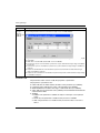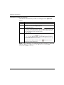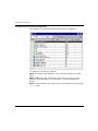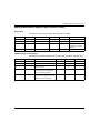
1
Modicon M340 with Unity Pro
35013944 07/2012
Modicon M340 with Unity
Pro
CANopen
User Manual
35013944.06
07/2012
www.schneider-electric.com
The information provided in this documentation contains general descriptions and/or
technical characteristics of the performance of the products contained herein. This
documentation is not intended as a substitute for and is not to be used for
determining suitability or reliability of these products for specific user applications. It
is the duty of any such user or integrator to perform the appropriate and complete
risk analysis, evaluation and testing of the products with respect to the relevant
specific application or use thereof. Neither Schneider Electric nor any of its affiliates
or subsidiaries shall be responsible or liable for misuse of the information contained
herein. If you have any suggestions for improvements or amendments or have found
errors in this publication, please notify us.
No part of this document may be reproduced in any form or by any means, electronic
or mechanical, including photocopying, without express written permission of
Schneider Electric.
All pertinent state, regional, and local safety regulations must be observed when
installing and using this product. For reasons of safety and to help ensure
compliance with documented system data, only the manufacturer should perform
repairs to components.
When devices are used for applications with technical safety requirements, the
relevant instructions must be followed.
Failure to use Schneider Electric software or approved software with our hardware
products may result in injury, harm, or improper operating results.
Failure to observe this information can result in injury or equipment damage.
© 2012 Schneider Electric. All rights reserved.
2
35013944 07/2012
Table of Contents
Safety Information . . . . . . . . . . . . . . . . . . . . . . . . . . . . . .
About the Book . . . . . . . . . . . . . . . . . . . . . . . . . . . . . . . . .
Part I CANopen Hardware Implementation . . . . . . . . . . . .
Chapter 1 Hardware Implementation of BMX P34 Processors . . .
Description of Processors: BMX P34 2010/20102/2030/20302 . . . . . . . .
Modicon M340H (Hardened) Equipment. . . . . . . . . . . . . . . . . . . . . . . . . .
Installation . . . . . . . . . . . . . . . . . . . . . . . . . . . . . . . . . . . . . . . . . . . . . . . . .
Visual Diagnostics of CANopen Processors . . . . . . . . . . . . . . . . . . . . . . .
Chapter 2 Presentation of CANopen devices . . . . . . . . . . . . . . . . .
7
9
11
13
14
15
16
17
21
CANopen Devices . . . . . . . . . . . . . . . . . . . . . . . . . . . . . . . . . . . . . . . . . . .
CANopen motion command devices . . . . . . . . . . . . . . . . . . . . . . . . . . . . .
CANopen Input/Output devices. . . . . . . . . . . . . . . . . . . . . . . . . . . . . . . . .
Other Devices . . . . . . . . . . . . . . . . . . . . . . . . . . . . . . . . . . . . . . . . . . . . . .
22
23
28
31
Part II Software Implementation of CANopen
Communication . . . . . . . . . . . . . . . . . . . . . . . . . . . . .
37
Chapter 3 Generalities . . . . . . . . . . . . . . . . . . . . . . . . . . . . . . . . . . . .
39
Implementation Principle . . . . . . . . . . . . . . . . . . . . . . . . . . . . . . . . . . . . . .
Implementation Method. . . . . . . . . . . . . . . . . . . . . . . . . . . . . . . . . . . . . . .
Performance . . . . . . . . . . . . . . . . . . . . . . . . . . . . . . . . . . . . . . . . . . . . . . .
Device PDO and Memory Allocation . . . . . . . . . . . . . . . . . . . . . . . . . . . . .
40
41
42
45
Chapter 4 Configuration of Communication on the CANopen Bus
49
4.1 General Points. . . . . . . . . . . . . . . . . . . . . . . . . . . . . . . . . . . . . . . . . . . . . .
Generalities . . . . . . . . . . . . . . . . . . . . . . . . . . . . . . . . . . . . . . . . . . . . . . . .
4.2 Bus Configuration . . . . . . . . . . . . . . . . . . . . . . . . . . . . . . . . . . . . . . . . . . .
How to Access the CANopen Bus Configuration Screen . . . . . . . . . . . . .
CANopen Bus Editor . . . . . . . . . . . . . . . . . . . . . . . . . . . . . . . . . . . . . . . . .
How to Add a Device on the Bus. . . . . . . . . . . . . . . . . . . . . . . . . . . . . . . .
How to Delete/Move/Duplicate a Bus Device . . . . . . . . . . . . . . . . . . . . . .
View CANopen Bus in the Project Browser. . . . . . . . . . . . . . . . . . . . . . . .
50
50
51
52
54
56
58
60
35013944 07/2012
3
4.3 Device Configuration . . . . . . . . . . . . . . . . . . . . . . . . . . . . . . . . . . . . . . . .
Slave Functions . . . . . . . . . . . . . . . . . . . . . . . . . . . . . . . . . . . . . . . . . . . .
Configuration Using Unity with CPUs 2010/ 2030 . . . . . . . . . . . . . . . . . .
Configuration Using Unity with CPUs 20102/ 20302 . . . . . . . . . . . . . . . .
Configuration Using an External Tool: Configuration Software . . . . . . . .
Manual Configuration. . . . . . . . . . . . . . . . . . . . . . . . . . . . . . . . . . . . . . . .
4.4 Master Configuration . . . . . . . . . . . . . . . . . . . . . . . . . . . . . . . . . . . . . . . .
How to Access the CANopen Master Configuration Screen . . . . . . . . . .
CANopen Master Configuration Screen with CPUs 2010/ 2030 . . . . . . .
Description of Master Configuration Screen for CPUs 2010/ 2030 . . . . .
CANopen Master Configuration Screen with CPUs 20102/ 20302 . . . . .
Description of Master Configuration Screen for CPUs 20102/ 20302 . . .
4
61
62
66
71
81
84
85
86
88
90
93
95
Chapter 5 Catalog Manager Software Implementation . . . . . . . . . .
99
5.1 Catalog Manager Overview . . . . . . . . . . . . . . . . . . . . . . . . . . . . . . . . . . .
Catalog Manager Description . . . . . . . . . . . . . . . . . . . . . . . . . . . . . . . . .
Catalog Manager Contents . . . . . . . . . . . . . . . . . . . . . . . . . . . . . . . . . . .
5.2 Using the Catalog Manager . . . . . . . . . . . . . . . . . . . . . . . . . . . . . . . . . . .
How to launch the Catalog Manager . . . . . . . . . . . . . . . . . . . . . . . . . . . .
How to add a device to the Catalog Manager . . . . . . . . . . . . . . . . . . . . .
How to add a function on a device. . . . . . . . . . . . . . . . . . . . . . . . . . . . . .
Basic configuration parameters . . . . . . . . . . . . . . . . . . . . . . . . . . . . . . . .
Expert Mode configuration parameters . . . . . . . . . . . . . . . . . . . . . . . . . .
MFB function for Expert Mode . . . . . . . . . . . . . . . . . . . . . . . . . . . . . . . . .
CANopen Compatibility Restrictions . . . . . . . . . . . . . . . . . . . . . . . . . . . .
How to copy or delete a function . . . . . . . . . . . . . . . . . . . . . . . . . . . . . . .
How to import/export or delete one or several user devices . . . . . . . . . .
How to close the Catalog Manager . . . . . . . . . . . . . . . . . . . . . . . . . . . . .
Example of how to create a dedicated and optimized STB Island . . . . .
5.3 Catalog Manager Troubleshooting. . . . . . . . . . . . . . . . . . . . . . . . . . . . . .
Troubleshooting . . . . . . . . . . . . . . . . . . . . . . . . . . . . . . . . . . . . . . . . . . . .
SDO Abort Code Description . . . . . . . . . . . . . . . . . . . . . . . . . . . . . . . . . .
EDS/DCF Import Anomaly Code . . . . . . . . . . . . . . . . . . . . . . . . . . . . . . .
100
101
104
108
109
110
113
115
119
131
137
138
139
142
143
144
145
149
150
Chapter 6 Programming . . . . . . . . . . . . . . . . . . . . . . . . . . . . . . . . . . .
153
Exchanges Using PDOs . . . . . . . . . . . . . . . . . . . . . . . . . . . . . . . . . . . . .
Exchanges Using SDOs . . . . . . . . . . . . . . . . . . . . . . . . . . . . . . . . . . . . .
Communication functions example . . . . . . . . . . . . . . . . . . . . . . . . . . . . .
Modbus request example. . . . . . . . . . . . . . . . . . . . . . . . . . . . . . . . . . . . .
154
159
162
168
Chapter 7 Debugging Communication on the CANopen Bus . . . . .
169
How to Access the Debug Screens of Remote Devices . . . . . . . . . . . . .
Debugging Screen of the CANopen Master for CPUs 2010/ 2030 . . . . .
Debugging Screen of the CANopen Master for CPUs 20102/ 20302 . . .
Slave Debug Screens . . . . . . . . . . . . . . . . . . . . . . . . . . . . . . . . . . . . . . .
170
171
173
175
35013944 07/2012
Chapter 8 Diagnostics . . . . . . . . . . . . . . . . . . . . . . . . . . . . . . . . . . . .
How to perform a diagnostic . . . . . . . . . . . . . . . . . . . . . . . . . . . . . . . . . . .
Master Diagnostics for CPUs 2010/ 2030 . . . . . . . . . . . . . . . . . . . . . . . . .
Master Diagnostics for CPUs 20102/ 20302 . . . . . . . . . . . . . . . . . . . . . . .
Slave Diagnostics . . . . . . . . . . . . . . . . . . . . . . . . . . . . . . . . . . . . . . . . . . .
Chapter 9 Language Objects. . . . . . . . . . . . . . . . . . . . . . . . . . . . . . .
177
178
179
180
183
185
9.1 General Information. . . . . . . . . . . . . . . . . . . . . . . . . . . . . . . . . . . . . . . . . .
Introduction to the Language Objects for CANopen Communication . . . .
Implicit Exchange Language Objects Associated with the ApplicationSpecific Function . . . . . . . . . . . . . . . . . . . . . . . . . . . . . . . . . . . . . . . . . . .
Details of IODDT Implicit Exchange Objects of Type T_COM_STS_GEN
Explicit Exchange Language Objects Associated with the ApplicationSpecific Function . . . . . . . . . . . . . . . . . . . . . . . . . . . . . . . . . . . . . . . . . . .
Details of IODDT Explicit Exchange Objects of Type T_COM_STS_GEN
Management of Exchanges and Reports with Explicit Objects . . . . . . . . .
9.2 Language Object of the CANopen Specific IODDT. . . . . . . . . . . . . . . . . .
Details of T_COM_CO_BMX IODDT . . . . . . . . . . . . . . . . . . . . . . . . . . . .
Details of T_COM_CO_BMX_EXPERT IODDT . . . . . . . . . . . . . . . . . . . .
Language Objects Associated with Configuration. . . . . . . . . . . . . . . . . . .
9.3 Emergency objects . . . . . . . . . . . . . . . . . . . . . . . . . . . . . . . . . . . . . . . . . .
Emergency Objects . . . . . . . . . . . . . . . . . . . . . . . . . . . . . . . . . . . . . . . . . .
190
192
194
196
197
210
223
225
225
Part III Quick start : example of CANopen implementation
229
Chapter 10 Description of the application . . . . . . . . . . . . . . . . . . . . .
Overview of the application . . . . . . . . . . . . . . . . . . . . . . . . . . . . . . . . . . . .
Chapter 11 Installing the application using Unity Pro . . . . . . . . . . .
11.1 Presentation of the solution used . . . . . . . . . . . . . . . . . . . . . . . . . . . . . . .
Technological choices used . . . . . . . . . . . . . . . . . . . . . . . . . . . . . . . . . . .
The different steps in the process using Unity Pro . . . . . . . . . . . . . . . . . .
11.2 Developping the application . . . . . . . . . . . . . . . . . . . . . . . . . . . . . . . . . . .
Creating the project . . . . . . . . . . . . . . . . . . . . . . . . . . . . . . . . . . . . . . . . . .
Configuration of the CANopen Bus . . . . . . . . . . . . . . . . . . . . . . . . . . . . . .
Configuration of the CANopen Master . . . . . . . . . . . . . . . . . . . . . . . . . . .
Configuration of the equipment . . . . . . . . . . . . . . . . . . . . . . . . . . . . . . . . .
Declaration of variables. . . . . . . . . . . . . . . . . . . . . . . . . . . . . . . . . . . . . . .
Creating the program in SFC for managing the move sequence . . . . . . .
Creating a Program in LD for Application Execution . . . . . . . . . . . . . . . . .
Creating a Program in LD for the operator screen animation . . . . . . . . . .
Creating a program in ST for the Lexium configuration. . . . . . . . . . . . . . .
Creating an Animation Table . . . . . . . . . . . . . . . . . . . . . . . . . . . . . . . . . .
Creating the Operator Screen . . . . . . . . . . . . . . . . . . . . . . . . . . . . . . . . . .
Chapter 12 Starting the Application . . . . . . . . . . . . . . . . . . . . . . . . . .
186
187
188
189
231
231
233
234
235
236
237
238
239
244
245
249
252
257
259
260
263
265
267
Execution of Application in Standard Mode. . . . . . . . . . . . . . . . . . . . . . . .
267
Appendices . . . . . . . . . . . . . . . . . . . . . . . . . . . . . . . . . . . . . . . . . . .
275
35013944 07/2012
5
6
Appendix A CANopen Master local object dictionary entry . . . . . . . .
277
Object Dictionary entries according Profile DS301 . . . . . . . . . . . . . . . . .
Object Dictionary entries according Profile DS302 . . . . . . . . . . . . . . . . .
Midrange Manufacturer Specific Object Dictionary Entries . . . . . . . . . . .
278
283
285
Appendix B Relation between PDOs and STB variables . . . . . . . . . .
293
STB island configuration . . . . . . . . . . . . . . . . . . . . . . . . . . . . . . . . . . . . .
293
Appendix C Actions and transitions . . . . . . . . . . . . . . . . . . . . . . . . . . .
297
Transitions . . . . . . . . . . . . . . . . . . . . . . . . . . . . . . . . . . . . . . . . . . . . . . . .
Actions . . . . . . . . . . . . . . . . . . . . . . . . . . . . . . . . . . . . . . . . . . . . . . . . . . .
298
299
Glossary . . . . . . . . . . . . . . . . . . . . . . . . . . . . . . . . . . . . . . . . . . .
Index . . . . . . . . . . . . . . . . . . . . . . . . . . . . . . . . . . . . . . . . . . .
301
307
35013944 07/2012
Safety Information
§
Important Information
NOTICE
Read these instructions carefully, and look at the equipment to become familiar with
the device before trying to install, operate, or maintain it. The following special
messages may appear throughout this documentation or on the equipment to warn
of potential hazards or to call attention to information that clarifies or simplifies a
procedure.
35013944 07/2012
7
PLEASE NOTE
Electrical equipment should be installed, operated, serviced, and maintained only by
qualified personnel. No responsibility is assumed by Schneider Electric for any
consequences arising out of the use of this material.
A qualified person is one who has skills and knowledge related to the construction
and operation of electrical equipment and its installation, and has received safety
training to recognize and avoid the hazards involved.
8
35013944 07/2012
About the Book
At a Glance
Document Scope
This manual describes the implementation of a CANopen network on PLCs of the
Modicon M340 range.
NOTE: Regarding Safety considerations, “Emergency objects” and “Fatal error” are
mentioned in this manual in conformance with the definition from the DS301
document of the CiA (CAN in Automation).
Validity Note
This documentation is valid from Unity Pro v7.0.
Product Related Information
WARNING
UNINTENDED EQUIPMENT OPERATION
The application of this product requires expertise in the design and programming
of control systems. Only persons with such expertise should be allowed to
program, install, alter, and apply this product.
Follow all local and national safety codes and standards.
Failure to follow these instructions can result in death, serious injury, or
equipment damage.
User Comments
We welcome your comments about this document. You can reach us by e-mail at
[email protected].
35013944 07/2012
9
10
35013944 07/2012
Modicon M340 with Unity Pro
CANopen Bus
35013944 07/2012
CANopen Hardware
Implementation
I
Subject of this Part
This part describes the various hardware configuration possibilities of a CANopen
bus architecture.
What Is in This Part?
This part contains the following chapters:
Chapter
35013944 07/2012
Chapter Name
Page
1
Hardware Implementation of BMX P34 Processors
13
2
Presentation of CANopen devices
21
11
CANopen Bus
12
35013944 07/2012
Modicon M340 with Unity Pro
CANopen on BMX P34 Processors
35013944 07/2012
Hardware Implementation of
BMX P34 Processors
1
Aim of this Chapter
This chapter presents BMX P34 processors equipped with a CANopen port as well
as their implementation.
To see the differences between the CPU P34 201/2030 and 20102/20302, please
refer to the chapter CANopen Compatibility Restrictions (see page 137).
What Is in This Chapter?
This chapter contains the following topics:
Topic
35013944 07/2012
Page
Description of Processors: BMX P34 2010/20102/2030/20302
14
Modicon M340H (Hardened) Equipment
15
Installation
16
Visual Diagnostics of CANopen Processors
17
13
CANopen on BMX P34 Processors
Description of Processors: BMX P34 2010/20102/2030/20302
At a Glance
Each PLC station is equipped with a BMX P34 ••••• processor.
There are five processors in the Modicon M340 range that have a CANopen port:
The BMX P34 2010/20102, which also has a USB port and serial port,
z The BMX P34 2030/20302/20302H (see page 15), which also has a USB port
and Ethernet port.
z
BMX P34 ••••• processors have a simple design, and include a memory card slot.
The following figures present the front sides of the BMX P34 2010 and BMX P34
2030:
Number
Designation
1
Display panel
2
USB Port.
3
SD-Card slot
4
SerialPort
5
Ethernet Port
6
CANopen Port
These processors are bus masters; they cannot function as slaves. They are linked
by SUB-D 9 connector points and allow the connection of slave devices which
support the CANopen protocol.
NOTE: There is only one BMX P34 ••••• master by bus.
14
35013944 07/2012
CANopen on BMX P34 Processors
Modicon M340H (Hardened) Equipment
M340H
The Modicon M340H (hardened) equipment is a ruggedized version of M340
equipment. It can be used at extended temperatures (-25...70ºC) (-13...158ºF) and
in harsh chemical environments.
This treatment increases the isolation capability of the circuit boards and their
resistance to:
z condensation
z dusty atmospheres (conducting foreign particles)
z chemical corrosion, in particular during use in sulphurous atmospheres (oil,
refinery, purification plant and so on) or atmospheres containing halogens
(chlorine and so on)
The M340H equipment, when within the standard temperature range (0...60ºC)
(32...140ºF), has the same performance characteristics as the standard M340
equipment.
At the temperature extremes (-25... 0ºC and 60... 70ºC) (-13...32ºF) and
(140...158ºF) the hardened versions can have reduced power ratings that impact
power calculations for Unity Pro applications.
If this equipment is operated outside the -25...70ºC (-13...158ºF) temperature range,
the equipment can operate abnormally.
CAUTION
UNINTENDED EQUIPMENT OPERATION
Do not operate M340H equipment outside of its specified temperature range.
Failure to follow these instructions can result in injury or equipment damage.
Hardened equipment has a conformal coating applied to its electronic boards. This
protection, when associated with appropriate installation and maintenance, allows it
to be more robust when operating in harsh chemical environments.
35013944 07/2012
15
CANopen on BMX P34 Processors
Installation
At a Glance
BMX P34 2010/20102 2030/20302 processors equipped with a CANopen port are
mounted on BMX XBP •••• racks fed by BMX CPS •••• modules.
NOTE: After an extract/insert of the processor while running, the bus is no longer
operational. In order to restart the bus, the power supply must be re-initialized.
CANopen Connectors
The CANopen processor port is equipped with a SUB-D9 connection.
The following figure represents the CANopen connector for modules (male) and
cables (female).
Pin
Signal
Description
1
-
Reserved
2
CAN_L
CAN_L bus line (Low)
3
CAN_GND
CAN mass
4
-
Reserved
5
Reserved
CAN optional protection
6
GND
Optional mass
7
CAN_H
CAN_H bus line (High)
8
-
Reserved
9
Reserved
CAN External Power Supply.
(Dedicated to the optocouplers power and transmittersreceivers.)
Optional
NOTE: CAN_SHLD and CAN_V+ are not installed on the Modicon M340 range
processors. These are reserved connections.
16
35013944 07/2012
CANopen on BMX P34 Processors
Visual Diagnostics of CANopen Processors
At a Glance
BMX P34 ••••• processors form the Modicon M340 range are equipped with several
Module Status visualization LEDs.
BMX P34 2010/20102/2030/20302 processors equipped with a CANopen port have
2 LEDs on their facade that indicate the bus status:
z
z
a green CAN RUN LED,
a red CAN ERR LED.
In normal operation, the CAN ERR LED is off and the CAN RUN LED is on.
The following figures show the LEDs on the facade of modules:
35013944 07/2012
17
CANopen on BMX P34 Processors
LED Status
The following trend diagram represents the possible status of LEDs:
18
35013944 07/2012
CANopen on BMX P34 Processors
Description
The following table describes the role of CAN RUN and CAN ERR LEDs:
Display
LED
On
Flash
Flashing
Off
Slow flashing
CAN RUN
(green)
The master is
operational.
SImple: The master is
stopped.
Triple : Loading of
CANopen firmware in
process.
The master is preoperational or
initialization in
progress.
-
Starting CANopen
master self-test.
CAN ERR
(red)
Bus stopped.
The CAN
controller has
status "BUS
OFF".
The CAN network is
disturbed.
Simple : at least one
of the counters has
attained or exceeded
the alert level.
Double : Monitoring
detected fault
(Nodeguarding or
Heartbeat)
OK.
Invalid
configuration, or
logic configuration
different from
physical
configuration:
missing, different
or additional slaves
detected.
35013944 07/2012
An anomaly occured
during the CANopen
coprocessor start.
The CANopen master
cannot start. If this
state is maintained,
you must change the
CPU.
19
CANopen on BMX P34 Processors
20
35013944 07/2012
Modicon M340 with Unity Pro
CANopen slaves
35013944 07/2012
Presentation of CANopen devices
2
Subject of this Section
This section presents the different CANopen devices.
What Is in This Chapter?
This chapter contains the following topics:
Topic
35013944 07/2012
Page
CANopen Devices
22
CANopen motion command devices
23
CANopen Input/Output devices
28
Other Devices
31
21
CANopen slaves
CANopen Devices
At a Glance
The devices that you can connect to a CANopen bus and that can be configured in
Unity Pro are grouped according to their functions:
z
z
z
motion command devices,
input/output devices,
other devices.
NOTE: Only devices from the Hardware Catalog can be used with Unity Pro. New
devices have to be imported to the Hardware Catalog from the Hardware Catalog
Manager. This import is available since Unity 4.0.
NOTE: An overview of the Hardware Catalog Manager in read only mode is
available in Unity Pro through the Hardware Catalog.
Motion Command Devices
Motion command devices enable you to control motors.
These devices are:
z
z
z
z
z
z
Altivar,
Lexium,
IcLA,
Osicoder,
Telsys T,
SD328A Stepper Drive.
Input/Output Devices
Input/Output modules function as remote modules. These devices are:
z
z
z
z
z
Tego Power devices,
Advantys FTB,
Advantys OTB,
Advantys FTM,
Preventa devices.
Other Devices
These are:
z
z
z
z
Advantys islands STB,
Tesys U,
Festo Valve Terminal,
Parker Moduflex.
The STB islands also allow the monitoring of inputs/outputs.
22
35013944 07/2012
CANopen slaves
CANopen motion command devices
At a glance
Motion command devices enable you to control motors.
These devices are:
z Altivar,
z Lexium,
z IcLA,
z Osicoder,
z Tesys T,
z SD328A Stepper Drive.
Altivar devices
An Altivar device enables to control the speed of a motor by flux vector control.
The following figure gives an example of an Altivar device:
NOTE: The recommended minimum version of the firmware is V1.3 for ATV31 T.
NOTE: The recommended minimum version of the firmware is V1.1 for ATV31,
ATV61 and ATV71.
NOTE: ATV31 V1.7 is not supported. However, it can be used by configuring it with
ATV31 1.2 profile. In this case, only the ATV31 V1.2 functions will be available
NOTE: ATV71: if you have to disconnect it from the CANopen bus, power off the
device, else, when reconnecting it on the bus, it will provoke a Bus Fatal error. This
is fixed with the ATV71 firmware version V1.2 and later.
NOTE: ATV61: if you have to disconnect it from the CANopen bus, power off the
device, else, when reconnecting it on the bus, it will provoke a Bus Fatal error. This
is fixed with the ATV61 firmware version V1.4 and later.
35013944 07/2012
23
CANopen slaves
Lexium devices
The range of Lexium 05 servo drives that are compatible with BSH servo motors
constitutes a compact and dynamic combination for machines across a wide power
(0,4...6 kW) and power supply voltage range.
The compact design of the Lexium 05 servo drive and the integrated components
(line filter, braking resistor and safety function) reduces the space required in the
switch cabinet to a minimum. It integrates the Power Removal safety function which
prevents accidental starting of the motor.
Another advantage of the servodrive Lexium 05 is the versatile application options:
as torque or speed controller via the analogue inputs,
z as electronic gearbox via the RS422 interface,
z as positioning or speed controller via the field bus interface.
z
The servodrive is available in four voltage types:
z 115 VAC single-phase,
z 230 VAC single-phase and 3-phase,
z 400/480 VAC 3-phase.
The following figure gives an example of a Lexium device:
NOTE: The recommended minimum version of the firmware for Lexium 05 MFB
device is V1.003
NOTE: The recommended minimum version of the firmware for Lexium 05 device is
V1.120.
NOTE: The recommended minimum version of the firmware for Lexium 15 LP is
V1.45.
NOTE: The recommended minimum version of the firmware for Lexium 15 MH is
V6.64.
24
35013944 07/2012
CANopen slaves
IcLA devices
IcLA devices are intelligent compact drives. They integrate everything required for
motion tasks: positioning controller, power electronics and servo, EC or stepper
motor.
The following figure gives an example of an IcLA device:
WARNING
UNINTENDED EQUIPMENT OPERATION
Use ICLA IFA devices with minimum firmware version V1.105.
Use ICLA IFE devices with minimum firmware version V1.104.
Use ICLA IFS devices with minimum firmware version V1.107.
Failure to follow these instructions can result in death, serious injury, or
equipment damage.
35013944 07/2012
25
CANopen slaves
Osicoder devices
The Osicoder device is an angular position sensor.
Mechanically coupled to a driving spindle of a machine, the shaft of the encoder
rotates a disc that comprises a succession of opaque and transparent sectors. Light
from leds passes through the transparent sectors of the disc as they appear and is
detected by photosensitive diodes. The photosensitive diodes, in turn, generate an
electrical signal which is amplified and converted into a digital signal before being
transmitted to a processing system or an electronic variable speed drive. The
electrical output of the encoder therefore represents, in digital form, the angular
position of the input shaft.
The following figure gives an example of an Osicoder device:
NOTE: The minimum version of the firmware for Osicoder devices is V1.0.
Tesys T Motor Management System
Tesys T is a motor management system that provides overload detection, metering
and monitoring functions for single-phase and 3-phase, constant speed, a.c. motors
up to 810 A.
Using Tesys T in a motor control panels makes it possible to:
Increase the operational availability of installations,
z improve flexibility from project design through to implementation,
z increase productivity by making available all information needed to run the
system.
z
The following figure gives an example of a Tesys T device:
26
35013944 07/2012
CANopen slaves
SD328A Stepper Drive
The SD328A is a universally applicable stepper drive.
It offers a very compact and powerful drive system in combination with selected
stepper motors by Schneider Electric Motion.
The device has an output for direct connection of an optional holding brake.
The following figure gives an example of a SD328A Stepper Drive device:
35013944 07/2012
27
CANopen slaves
CANopen Input/Output devices
At a glance
The Input/Output modules function as remote modules.
These devices are:
z
z
z
z
z
Tego Power devices,
Advantys FTB,
Advantys OTB,
Advantys FTM,
Preventa devices.
Tego Power devices
Tego Power is a modular system which standardizes and simplifies the implementation of motor starters with its pre-wired control and power circuits. In addition, this
system enables the motor starter to be customized at a later date, reduces
maintenance time and optimizes panel space by reducing the number of terminals
and intermediate interfaces and also the amount of ducting.
The following figure gives an example of a Tego Power device:
NOTE: The minimum version for TegoPower APP_1CCO0 and TegoPower
APP_1CCO2 is V1.0
28
35013944 07/2012
CANopen slaves
Advantys FTB devices
The Advantys FTB dispatcher is composed of several input/outputs that allow
sensors and activators to be connected.
NOTE: The minimum firmware version for FTB is V1.07
NOTE: For FTB 1CN16CM0, operating is guaranteed from the minimum firmware
version V1.05
The following figure gives an example of an Advantys FTB device:
Advantys OTB devices
An Advantys OTB device enables you to constitute discrete input/output islands
(max.132 channels in boundaries) or analog (max. 48 channels) IP20 and to
connect them close to the active captors.
The following figure gives an example of an Advantys OTB device:
NOTE: The minimum firmware version for OTB is V2.0
WARNING
UNINTENDED EQUIPMENT OPERATION
Use Advantys OTB devices with minimum firmware version V2.0.
Failure to follow these instructions can result in death, serious injury, or
equipment damage.
35013944 07/2012
29
CANopen slaves
Advantys FTM CANopen
The Advantys FTM modular system enables you to connect a variable number of
input/output splitter boxes, using a single communication interface (field bus
module).
These splitter boxes are connected to the module using a hybrid cable which
includes the internal bus and power supply (internal, sensor and actuator).
The input/output splitter boxes are independent of the field bus type, thus reducing
the number of splitter box references. Once installed, the system is ready to begin
operation.
The following figure gives an example of an Advantys FTM CANopen device:
Preventa devices
Preventa devices are electronic safety controllers for monitoring safety functions.
The following figure gives an example of a Preventa device:
30
35013944 07/2012
CANopen slaves
Other Devices
At a Glance
These devices are:
z
z
z
z
STB Island,
Tesys U,
Festo Valve Terminal,
Parker Moduflex.
STB Island
An Advantys STB island is composed of several input/output modules.
The modular elements of the island are connected by a CANopen local bus using a
network interface module NIM.
STB modules can only be used in an STB island.
The following figure gives an example of an island:
35013944 07/2012
31
CANopen slaves
Description:
Number
Designation
1
Network Interface Module.
2
Power supply Distribution Module.
3
Distributed input/output modules. These modules can be:
z digital input/output modules,
z analog input/output modules,
z special purposes.
4
Termination plate of island bus.
Tesys U Devices
TeSys U-Line motor starters provide motor control for choices ranging from a basic
motor starter with solid-state thermal overload protection to a sophisticated motor
controller which communicates on networks and includes programmable motor
protection.
This device performs the following functions:
z
z
32
Protection and control of 1-phase or 3-phase motors:
z Isolation breaking function
z
Electronic short-circuit protection
z
Electronic overload protection
z
Power switching
Control of the application:
z Status (protection functions, e.g. overload pending)
z
Status monitoring (running, ready, ....)
z
Application monitoring (running time, number of anomalies, motor current
values)
z
Detected fault logging (last 5 anomalies saved, together with motor parameter
values).
35013944 07/2012
CANopen slaves
The following figure gives an example of a Tesys U device:
35013944 07/2012
33
CANopen slaves
Festo valve terminal
CPV Direct:
CPV valves are series manifold valves, in addition to the valve function they contain
all of the pneumatic ducts for supply, exhaust and the working lines.
The supply ducts are a central component of the valve slices and allow a direct flow
of air through the valve slices. This helps achieve maximum flow rates. All valves
have a pneumatic pilot control for optimising performance.
The fieldbus node is directly integrated in the electrical interface of the valve
terminal and therefore takes up only a minimal amount of space.
The optional string extension allows an additional valve terminal and I/O modules
to be connected to the Fieldbus Direct fieldbus node.
The CPV valve terminal is available in three sizes:
z
z
z
CPV10
CPV14
CPV18
The following figure gives an example of a Festo valve terminal device:
34
35013944 07/2012
CANopen slaves
CPX Terminal:
The electrical terminal CPX is a modular peripheral system for valve terminals. The
system is specifically designed so that the valve terminal can be adapted to suit
different applications.
Variable connection options for the valve terminal pneumatic components
(MPA/CPA/VTSA)
Flexible electrical connection technology for sensors and actuators
The CPX terminal can also be used without valves as a remote I/O system.
The following figure gives an example of a CPX terminal device:
Parker Moduflex
Parker Moduflex Valve System provides flexible pneumatic automation.
Depending on application, you can assemble short or long islands (up to 16
outputs). IP 65-67 water and dust protection allows the valve to be installed near the
cylinders for shorter response time and lower air consumption. The Parker Moduflex
Valve System CANopen module (P2M2HBVC11600) can be used as an enhanced
CANopen device in an Modicon M340 configuration.
The firmware version of the P2M2HBVC11600 must be V 1.4 or later.
For detailed descriptions of P2M2HBVC11600 wiring, LED patterns, set-up
procedures, and functionality, refer to user documentation provided by Parker.
"S" Series Stand-Alone Valves:
For isolated cylinders on a machine, it is preferable to locate the valve close by.
Therefore a stand-alone module is ideal, response time and air consumption are
then reduced to a minimum. Peripheral modules can be installed directly into the
valve.
35013944 07/2012
35
CANopen slaves
The following figure gives an example of a "S" Series Single Solenoid device:
The following figure gives an example of a "S" Series Single Air Pilot device:
"T" Series Valve Island Modules
For small groups of cylinders requiring short localized valve islands.
Modules with different functions and flow passages may be combined in the same
island manifold, giving total flexibility to adapt to all machine requirements.
The following figure gives an example of a "T" Series Valve Island Module device:
36
35013944 07/2012
Modicon M340 with Unity Pro
CANopen Bus
35013944 07/2012
Software Implementation of
CANopen Communication
II
Subject of this Part
This part describes the various possibilities for software configuration, programming
and diagnostics in a CANopen application.
What Is in This Part?
This part contains the following chapters:
Chapter
35013944 07/2012
Chapter Name
Page
3
Generalities
39
4
Configuration of Communication on the CANopen Bus
49
5
Catalog Manager Software Implementation
99
6
Programming
153
7
Debugging Communication on the CANopen Bus
169
8
Diagnostics
177
9
Language Objects
185
37
CANopen Bus
38
35013944 07/2012
Modicon M340 with Unity Pro
35013944 07/2012
Generalities
3
Subject of this Chapter
This chapter describes CANopen software implementation principles on the
Modicon M340 bus.
What Is in This Chapter?
This chapter contains the following topics:
Topic
35013944 07/2012
Page
Implementation Principle
40
Implementation Method
41
Performance
42
Device PDO and Memory Allocation
45
39
Implementation Principle
At a Glance
In order to implement a CANopen bus, it is necessary to define the physical context
of the application in which the bus is integrated (rack, supply, processor, modules),
and then ensure that the necessary software is implemented.
The software is implemented in two ways with Unity Pro:
In offline mode
z In online mode
z
Implementation Principle
The following table shows the different implementation phases:
Mode
Phase
Offline
Configuration
Entry of configuration parameters.
Offline or online
Symbolization
Symbolization of the variables associated with the CANopen
port of the BMX P34 ••••processor.
Programming
Programming the specific functions:
z Bit objects or associated words
z Specific instructions
Transfer
Transferring the application to the PLC.
Debugging
Diagnostics
Different resources are available for debugging the
application, controlling inputs/outputs and diagnostic
messages:
z Language objects or IODDTs
z The Unity Pro debugging screen
z Signaling by LED
Documentation
Printing the various information relating to the configuration of
the CANopen port.
Online
Offline or online
Description
NOTE: The above order is given for your information. Unity Pro software enables
you to use editors in the desired order of interactive manner.
WARNING
UNINTENDED EQUIPMENT OPERATION
Use diagnosis system information and monitor the response time of the
communication. In case of disturbed communication, the response time can be too
high.
Failure to follow these instructions can result in death, serious injury, or
equipment damage.
40
35013944 07/2012
Implementation Method
Overview
The following flowchart shows the CANopen port implementation method for
BMX P34 •••• processors:
35013944 07/2012
41
Performance
Introduction
Various CANopen performances are detailed below.
Impact on Task Cycle Time
The time given to each task cycle is as follows:
Task
42
Typical
CANopen inputs
10 μs / PDO
CANopen outputs
80 μs + 15 μs / PDO
Diagnostics
120 μs
35013944 07/2012
Communication by SDO
The following figure gives an overview of the SDO management:
The following table defines the terms that are used to describes the ‘Communication
by SDO’ graphic:
Term
Definition
Tcycle
User task cycle
n
Number of SDO to execute in parallel
Tsdo
Time to process the n SDOs (multiple of 5 ms due to the polling task)
Average
time
Average time to execute all the SDO from SDO1 to SDOn.
The average time depends on the Tcycle, n and Tsdo:
z If Tcycle > Tsdo then Average time=Tcycle
z If Tcycle < Tsdo then Average time=NB * Tcycle and NB=Tsdo/(Tcycle+1)
NOTE: A polling task runs every 5 ms and at each task cycle in order to check the
end of the exchange.This is useful if the user runs many SDOs.
35013944 07/2012
43
Example: for a task cycle of 50 ms, a number of 10 SDOs/Mast Cycle and a SDO
exchange time of 3 ms.
With the polling task, you can treat 2 SDOs/5ms. In order to do that, these SDOs
must be addressed to two different devices.
Therefore, we can launch 10 SDOs/task cycle.
Bus Start
The CANopen bus start time depends on the number of devices.
The minimum time to start a CANopen bus is 7 seconds.
The time to configure one device is about 0.8 second.
The start time of a CANopen bus with 64 devices is about 1 minute.
Disconnection/Reconnection of a Device
Disconnection:
The time to detect the disconnection of a device depends on the error control:
Error control
Description
Guardtime
The time to detect the disconnection is Guardtime * life
time factor
Heartbeat
The time to detect the disconnection is Heartbeat
producer time + (Heartbeat producer time /2)
Reconnection:
Each second, the master polls on the device to check the reconnection of the device.
The time to reconnect the device is about 1 second if the device is not alone on the
bus.
If the device is alone on the bus, the disconnection of the device set the master in
the same case as the disconnection of the complete bus. After this state, the master
restarts the bus and the reconnection time of the device is about 7 seconds.
44
35013944 07/2012
Device PDO and Memory Allocation
At a glance
The following table describes limits for each device and therefore specifies the
maximum configuration of the application:
Familly
Device
Motor
Control
APP_1CC00
Detection
F*
Tx
PDO
Rx
PDO
Tx Cob Rx Cob Extra
Id
Id
Cob Id
%MW %MW %M
IN
OUT IN
%M
OUT
5
5
4
4
0
4
2
2
0
APP_1CC02
5
5
4
4
2
8
6
0
0
TeSysT_MMC_L
4
4
4
4
0
46
8
0
0
TeSysT_MMC_L_EV40
4
4
4
4
0
62
12
0
0
TeSysT_MMC_R
4
4
4
4
0
46
8
0
0
TeSysT_MMC_R_EV40
4
4
4
4
0
62
12
0
0
TeSysU_C_Ad
4
4
4
4
0
16
8
0
0
TeSysU_C_Mu_L
4
4
4
4
0
50
10
0
0
TeSysU_C_Mu_R
4
4
4
4
0
38
12
0
0
TeSysU_Sc_Ad
4
4
4
4
0
14
10
0
0
TeSysU_Sc_Mu_L
4
4
4
4
0
48
10
0
0
TeSysU_Sc_Mu_R
4
4
4
4
0
36
12
0
0
TeSysU_Sc_St
4
4
4
4
0
14
10
0
0
Osicoder
2
0
2
0
0
2
0
0
0
Distributed FTB_1CN08E08CMO
I/O
FTB_1CN08E08SP0
2
2
2
2
0
2
0
40
8
2
2
2
2
0
2
0
0
8
35013944 07/2012
45
Familly
Device
F*
Tx
PDO
Rx
PDO
Tx Cob Rx Cob Extra
Id
Id
Cob Id
%MW %MW %M
IN
OUT IN
%M
OUT
FTB_1CN12E04SP0
2
2
2
2
0
2
0
28
4
FTB_1CN16CM0
2
2
2
2
0
2
0
56
16
FTB_1CN16CP0
2
2
2
2
0
2
0
56
16
FTB_1CN16EM0
2
2
2
2
0
2
0
24
0
FTB_1CN16EP0
2
2
2
2
0
2
0
24
0
FTM_1CN10
5
5
4
4
2
54
50
0
0
OTB Island
Sta
8
8
4
4
8
68
20
0
0
Ext
6
8
4
4
6
102
54
0
0
8
8
4
4
8
38
10
0
0
STB_NCO_1010
Sim
32
32
4
4
56
132
96
0
0
Ext
32
32
4
4
56
228
192
0
0
STB_NCO_2212
Sim
32
32
4
4
56
132
96
0
0
OTB_1C0_DM9LP
Motion &
Drives
ATV31_V1_1
ATV31_V1_2
ATV31_V1_7
46
Ext
32
32
4
4
56
228
192
0
0
Adv
32
32
4
4
56
278
244
0
0
Lar
32
32
4
4
56
694
484
0
0
Bas
2
2
2
2
0
4
4
0
0
Sta
2
2
2
2
0
6
10
0
0
Ext
2
2
2
2
0
20
16
0
0
Bas
2
2
2
2
0
4
4
0
0
Sta
2
2
2
2
0
6
10
0
0
Ext
2
2
2
2
0
20
16
0
0
MFB 2
2
2
2
0
2
2
0
0
Bas
2
2
2
2
0
4
4
0
0
Sta
2
2
2
2
0
6
10
0
0
Ext
2
2
2
2
0
20
16
0
0
35013944 07/2012
Familly
Device
ATV31T_V1_3
ATV61_V1_1
ATV71_V1_1
IclA_IFA
IclA_IFE
IclA_IFS
F*
Tx
PDO
Rx
PDO
Tx Cob Rx Cob Extra
Id
Id
Cob Id
%MW %MW %M
IN
OUT IN
%M
OUT
Bas
2
2
2
2
0
4
4
0
0
Sta
2
2
2
2
0
6
10
0
0
Ext
2
2
2
2
0
20
16
0
0
Bas
3
3
3
3
0
8
8
0
0
Sta
3
3
3
3
0
32
20
0
0
Ext
3
3
3
3
0
70
62
0
0
Con
3
3
3
3
0
76
62
0
0
Bas
3
3
3
3
0
8
8
0
0
Sta
3
3
3
3
0
16
10
0
0
Ext
3
3
3
3
0
22
14
0
0
Con
3
3
3
3
0
80
58
0
0
MFB 3
3
3
3
0
6
6
0
0
Def
1
1
1
1
0
8
10
0
0
MFB 1
1
1
1
0
6
6
0
0
Def
1
1
1
1
0
8
10
0
0
MFB 1
1
1
1
0
6
6
0
0
Def
1
1
1
1
0
8
10
0
0
MFB 1
1
1
1
0
6
6
0
0
LXM05_MFB
4
4
4
4
0
10
10
0
0
LXM05_V1_12
4
4
4
4
0
24
26
0
0
LXM15LP_V1_45
LXM15MH_V6_64
SD3_28
Safety
Def
4
4
4
4
0
8
10
0
0
4
4
4
4
0
96
134
0
0
MFB 4
4
4
4
0
8
10
0
0
4
4
4
4
0
22
20
0
0
XPSMC16ZC
4
0
4
0
0
28
0
0
0
XPSMC32ZC
4
0
4
0
0
28
0
0
0
35013944 07/2012
47
Familly
Device
Third-party CPV_C02
devices
CPX_FB14
F*
Tx
PDO
Rx
PDO
Tx Cob Rx Cob Extra
Id
Id
Cob Id
%MW %MW %M
IN
OUT IN
%M
OUT
Bas
1
1
1
1
0
8
4
0
0
Adv
1
1
1
1
0
10
6
0
0
CpEx 1
1
1
1
0
10
4
0
0
BDIO 4
4
4
4
0
56
50
0
0
GDIO 4
4
4
4
0
26
20
0
0
Adv
4
4
4
4
0
72
66
0
0
1
1
1
1
0
2
2
0
0
P2M2HBVC11600
Legend for F*
Ext
Extended
Sta
Standard
Sim
Simple
Lar
Large
Bas
Basic
MFB
MFB
Con
Controler
Def
Default
Adv
Advanced
CpEx
CP Extension
BDIO
Basic DIO only
GDIO
Generic DIO AIO
F* : Function
48
35013944 07/2012
Modicon M340 with Unity Pro
CANopen Configuration
35013944 07/2012
Configuration of Communication
on the CANopen Bus
4
Aim of this Chapter
This chapter presents the configuration of the CANopen field bus and of the bus
master and slaves.
What Is in This Chapter?
This chapter contains the following sections:
Section
35013944 07/2012
Topic
Page
4.1
General Points
4.2
Bus Configuration
51
4.3
Device Configuration
61
4.4
Master Configuration
85
50
49
CANopen Configuration
4.1
General Points
Generalities
Introduction
Configuration of a CANopen architecture is integrated into Unity Pro.
When the channel of the CANopen master has been configured, a node is
automatically created in the project browser. It is then possible to launch Bus Editor
from this node in order to define the topology of the bus and configure the CANopen
elements.
NOTE: You cannot modify the configuration of the CANopen bus in connected
mode.
50
35013944 07/2012
CANopen Configuration
4.2
Bus Configuration
Subject of this Section
This section presents the configuration of the CANopen bus.
What Is in This Section?
This section contains the following topics:
Topic
35013944 07/2012
Page
How to Access the CANopen Bus Configuration Screen
52
CANopen Bus Editor
54
How to Add a Device on the Bus
56
How to Delete/Move/Duplicate a Bus Device
58
View CANopen Bus in the Project Browser
60
51
CANopen Configuration
How to Access the CANopen Bus Configuration Screen
At a Glance
This describes how to access the configuration screen of the CANopen bus for a
Modicon M340 PLC with a built-in CANopen link.
Procedure
To access the CANopen field bus, perform the following actions:
Step
1
52
Action
From the project navigator, deploy the Configuration directory.
Result: the following screen appears:
35013944 07/2012
CANopen Configuration
Step
2
Action
To open the CANopen bus screen, select one of the following methods:
z double-click on the CANopen directory,
z select the CANopen sub-directory and select Openin the contextual menu.
Result: the CANopen window appears:
35013944 07/2012
53
CANopen Configuration
CANopen Bus Editor
At a Glance
This screen is used to declare devices which are connected to the bus.
Illustration
The CANopen bus editor looks like this:
54
35013944 07/2012
CANopen Configuration
Elements and Functions
This table describes the different areas that make up the configuration screen:
Number Element
1
Function
Bus
Bus number.
Connections
configured
Indicates the number of connection points configured.
2
Logical address
area
This area includes the addresses of the devices connected
to the bus.
3
Module area
This area includes the devices that are connected to the
bus.
Available connection points are indicated by an empty white square.
35013944 07/2012
55
CANopen Configuration
How to Add a Device on the Bus
Procedure
This operation is used to add, via the software, a device connected to the CANopen
bus:
Step
56
Action
1
Access the CANopen (see page 52) configuration screen.
2
Double-click on the place where the module should be connected.
Result: the New Device screen appears.
3
Enter the number of the connection point corresponding to the address.
By default, the Unity Pro software offers the first free consecutive address.
4
In the Communicator field, select the element type enabling communication on the CANopen bus.
For modules with built-in communicators, this window does not appear.
35013944 07/2012
CANopen Configuration
Step
5
35013944 07/2012
Action
Validate with Ok.
Result: the module is declared.
57
CANopen Configuration
How to Delete/Move/Duplicate a Bus Device
Procedure for Deleting a Device
This operation is used to delete, via the software, a device connected to the
CANopen bus:
Step
Action
1
Access the CANopen configuration screen.
2
Right-click on the connection point of the device to be deleted, then click on
Delete the drop.
Procedure for Moving a Device
Moving a device does not involve a physical move on the bus, but rather a change
in the device address logic. A movement thus triggers modification of the address of
inputs/outputs objects in the program and movement of the variables associated
with these objects.
Step
58
Action
1
Access the CANopen configuration screen.
2
Select the connection point to be moved (a frame surrounds the selected connection point).
3
Drag and drop the connection point to be moved to an empty connection point.
Result: the Move Device screen appears:
4
Enter the number of the destination connection point.
5
Confirm the new connection point by pressing OK.
Result: the Move Device screen appears:
6
Confirm the modification by pressing Yes to modify the addresses of the inputs/outputs objects in the
program and move the variables associated with these objects.
35013944 07/2012
CANopen Configuration
Procedure for Duplicating a Device
This feature is similar to the function for moving a device:
Step
Action
1
Access the CANopen configuration screen.
2
Right-click on the device to be copied, then click on Copy.
3
Right-click on the connection point desired, then click on Paste.
Result: the New Device screen appears:
4
Enter the number of the destination connection point.
5
Confirm the new connection point by pressing OK.
35013944 07/2012
59
CANopen Configuration
View CANopen Bus in the Project Browser
At a Glance
The CANopen bus is shown is the configuration directory in the project browser. The
number of the bus is calculated automatically by Unity Pro.
NOTE: The value of the bus number cannot be modified.
The following illustration shows the CANopen bus and slaves in the project browser:
60
35013944 07/2012
CANopen Configuration
4.3
Device Configuration
Subject of this Section
This section presents the configuration of the initial parameters of the CANopen
devices.
There are three ways of configuring the initial parameters:
z
z
z
Configuration using Unity,
Configuration using an external tool,
Manual Configuration.
NOTE: Before configuring a device, it is strongly recommended to select the
function, when available.
What Is in This Section?
This section contains the following topics:
Topic
35013944 07/2012
Page
Slave Functions
62
Configuration Using Unity with CPUs 2010/ 2030
66
Configuration Using Unity with CPUs 20102/ 20302
71
Configuration Using an External Tool: Configuration Software
81
Manual Configuration
84
61
CANopen Configuration
Slave Functions
At a Glance
So as to facilitate their configuration, certain CANopen devices are represented
through functions.
Each function defines premapped PDOs, as well as certain debugging variables
which can be mapped (PDO tab of the slave configuration screen).
NOTE: The function should be selected before configuring the slave.
Available Functions
The available functions are as follows:
Function
Description
Devices
involved
Basic
This function allows a simple control of the speed.
Altivar
MFB
This function allows control of the device through PLCOpen Motion function block
library.
Standard
This function allows control of the speed and/or torque.
All the parameters that can be mapped are mapped in the supplemental PDOs for:
z an adjustment of the operating parameters (length of acceleration,),
z additional surveillance (current value,...),
z additional control (PID, outputs command,...).
Advanced
This function allows control of the speed and/or torque.
Certain parameters can be configured and can also be mapped in the PDOs to
allow:
z an adjustment of the operating parameters (length of acceleration,),
z additional surveillance (current value,...),
z additional control (PID, outputs command,...).
62
35013944 07/2012
CANopen Configuration
Function
Description
Devices
involved
Simple
Use this profile if the island does not contain high resolution analog I/O module or
the TeSys U STB modules.
This profile contains:
z NIM diagnostic information (index 4000-index 4006),
z 8-bit discrete input information (index 6000),
z 16-bit discrete information (index 6100),
z 8-bit discrete output information (index 6200),
z 16-bit discrete output information (index 6300),
z low resolution analog input information (index 6401),
z low resolution analog output information (index 6411).
STB
NCO1010 &
NCO2212
This profile limits the number of index or subindex entries for any of the above
objects to 32. If the island configuration exceeds this limitation, please use the
Large profile.
Extended
Use this profile if the island contains high resolution analog I/O module or the
TeSys U STB modules.
This profile contains
z NIM diagnostic information (index 4000-index 4006),
z 8-bit discrete input information (index 6000),
z 16-bit discrete information (index 6100),
z 8-bit discrete output information (index 6200),
z 16-bit discrete output information (index 6300),
z low resolution analog input information (index 6401),
z low resolution analog output information (index 6411),
z high resolution analog input information or HMI words (index 2200-221F),
z high resolution analog output information or HMI words (index 3200-321F),
z TeSys U input information (index 2600-261F),
z TeSys U output information (index 3600-361F).
This profile limits the number of index or subindex entries for any of the above
objects to 32. If the island configuration exceeds this limitation, please use the
Large profile.
35013944 07/2012
63
CANopen Configuration
Function
Description
Devices
involved
Advanced
Use this profile if the island contains enhanced CANopen devices, special features STB
as run-time parameters along with high resolution analog I/O module or HMI or the NCO2212
TeSys U STB modules.
This profile contains:
z NIM diagnostic information (index 4000-index 4006),
z 8-bit discrete input information (index 6000),
z 16-bit discrete information (index 6100),
z 8-bit discrete output information (index 6200),
z 16-bit discrete output information (index 6300),
z low resolution analog input information (index 6401),
z low resolution analog output information (index 6411),
z high resolution analog input information or HMI words (index 2200-221F),
z high resolution analog output information or HMI words (index 3200-321F),
z TeSys U input information (index 2600-261F),
z TeSys U output information (index 3600-361F),
z 3rd party CANopen devices (index 2000-201F),
z RTP information (index 4100 & index 4101).
This profile limits the number of index or subindex entries for any of the above
objects to 32. If the island configuration exceeds this limitation, please use the
Large profile.
Large Profile
Use this profile if the island configuration does not fit any of the above profiles. This STB
profile contains all the objects available for the STB island and hence will consume NCO1010 &
NCO2212
more memory address location in the CANopen master.
Controlling
This function is especially created for CANopen communications with the built-in
controller card and all the application cards (pump control,...).
Altivar
61/71
Basic
The basic level is designed to configure the valve terminal without CP extension.
Festo CPV
CP_Extension
This level is designed to configure I/Os including the CP extension.
Basic_DIO_only
The basic level is designed to configure the CPX with pneumatic valves and Digital Festo CPX
I/O only.
Generic_DIO_AIO The generic DS401 level is designed to configure CPX valves and I/Os, including
Analogue I/O modules.
Advanced
64
The advanced level is designed to configure the maximum I/Os and the complete
parameters set.
35013944 07/2012
CANopen Configuration
Function
Description
Devices
involved
Default
This feature is the default function for certain devices. It may not be modified.
All the
slaves
except ATV
and Lexium
NOTE: Some devices can only handle one function. In this case, the function
appears grayed out and cannot be modified.
35013944 07/2012
65
CANopen Configuration
Configuration Using Unity with CPUs 2010/ 2030
At a Glance
The devices which can be configured using Unity are shown in the Hardware
Catalog:
Procedure
To configure a slave, perform the following actions:
Step
66
Action
1
Access the CANopen (see page 52) bus configuration screen.
2
Double-click on the slave to be configured.
3
Configure the usage function using the Config tab.
4
Configure the PDOs using the PDO tab.
5
Select the error control using the Error control tab.
35013944 07/2012
CANopen Configuration
Config tab
The following figure shows an example of the configuration screen of a slave:
35013944 07/2012
67
CANopen Configuration
The next table shows the various elements of the configuration screen and their
functions:
Number
Element
Function
1
Tabs
The tab in the foreground indicates the type of screen displayed.
In this case, it is the configuration screen.
2
Module area
Gives a reminder of the device’s shortened name.
3
Channel area
This zone allows you to select the communication channel to be
configured.
By clicking on the device, you display the following tabs:
z Description : gives the characteristics of the device,
z CANopen: allows you to access SDO (see page 159) (in
online mode),
z I/O Objects: allows pre-symbolizing of the input/output
objects,
z Fault: accessible in online mode only.
By clicking on the channel, you display the following tabs:
PDO(input/output objects)
Error control,
Configuration.
Debug which can be accessed only in online mode.
Diagnostics, accessible only in Online mode.
z
z
z
z
z
This field allows you to select the slave function.
4
General
parameters
area
5
Configuration This area is used to set up the channels of the devices.
area
Some devices can be configured with an external tool. In this
case, the configuration is stored in the device and you cannot
enter configuration parameters because this field is empty.
NOTE: Refer to the documentation of each device for information on general,
configuration, adjustment and debugging parameters.
NOTE: All parameters are not sent when the device takes its configuration. The
CPU send only parameters which are different from the default values.
68
35013944 07/2012
CANopen Configuration
PDO Tab
PDOs make it possible to manage the communication flow between the CANopen
Master and the slaves. The PDO tab allows to configure a PDO.
This screen is divided into 3 parts:
z
z
z
Transmit PDOs: information transmitted by the Slave to the Master,
Receive PDOs: information received by the Slave from the Master,
Variables: variables that can be mapped to the PDOs. To assign a variable to a
PDO, drag and drop the variable into the desired PDO. No variable can be
assigned with a static PDO.
NOTE: To configure the STB NCO 1010, it’s necessary to determine all the objects
that are valid for this device and to configure them manually in the PDOs.
For more information about the list of the associated objects, please refer to the STB
user manual.
For more information about the use of the PDOs, see [...].
35013944 07/2012
69
CANopen Configuration
Error Control Tab
The Error control tab for CANopen slave modules allows you to configure
monitoring.
Two choices are possible:
z
z
Heartbeat: The Heartbeat mechanism consists of sending cyclical presence
messages generated by a Heartbeat Producer. A Heartbeat transmitter
(producer) sends messages recurringly. The sending time is configured with the
Node Heartbeat Procucer Time Value. One or several elements
connected to the network receive this message. The Heartbeat consumer
surveys the Heartbeat message reception. The default value of consumer time is
set to (1.5 * Producer Heartbeat Time). If its duration exceeds the
Heartbeat Consumer Time (1.5 * Producer Heartbeat Time), an
Hearbeat event is created and the device is in default.
If a M340 Master PLC is used on the CANopen bus, all the nodes using the
Heartbeat control mode are producers. The master surveys the transmission and
the reception of the messages and it is the only receiver of the Heartbeat
messages sent by the nodes
Unity supports devices that are only heartbeat producer (no consumer) and does
not support the node guarding. In this case, the value of node heartbeat
consumer time is set to 0. This value is displayed on the error control tab of the
device.
The Master can send Heartbeat messages to the slaves. The Master Heartbeat
producer time is set at 200 ms and is not modifiable.
Node guarding: Node Guarding is the monitoring of network nodes. The NMT
(Network Management) master sends an RTR (Remote Transmission Request)
at regular intervals (this period is called Guard Time) and the concerned node
must answer in a given time lapse (the Node Life Time equals the Guard Time
multiplied by the Life Time Factor).
The Life Time value is set at 2 and is not modifiable.
NOTE: Some devices only support Heartbeat or Node Guarding. For devices which
support Heartbeat and Node Guarding, the only choice in Unity Pro is the Heartbeat
mechanism.
70
35013944 07/2012
CANopen Configuration
Configuration Using Unity with CPUs 20102/ 20302
At a Glance
The devices which can be configured using Unity are shown in the Hardware
Catalog:
Procedure
To configure a slave, perform the following actions:
Step
35013944 07/2012
Action
1
Access the CANopen (see page 52) bus configuration screen.
2
Double-click on the slave to be configured.
3
Configure the Bootup Procedure using the Bootup tab.
4
Integrate a third pary product using the Object Dictionary tab.
5
Configure the usage function using the Config tab.
6
Configure the PDOs using the PDO tab.
7
Select the error control using the Error control tab.
71
CANopen Configuration
Configuration Tab
The following figure shows an example of the configuration screen of a slave:
1
\3.1\0.0 : IcIA_IFA
2
IcI-IFA CANopen (IcIA-IFA.eds)
IcIA_IFA
Channel 0
PDO
Error control
Index
3
Function:
4
Default
MAST
Object dictionary
Bootup
Label
Configuration
Value
0
300B:01
Settings.name1
0
1
300B:02
Settings.name2
0
2
300B:06
Commandes.eeprSave
0
3
300B:08
Commands.default
0
4
300F:03
Settings.l_max
0
5
300F:04
Setting.l_maxStop
0
6
300F:08
Control.KPn
0
7
300F:09
Control.TNn
0
8
300F:0A
Control.KPp
0
9
300F:0B
Control.KFPn
0
10
300F:0D
Status.p_difPeak
0
11
300F:0F
Settings.p_win
0
12
300F:10
Settings.p_winTime
0
13
300F:11
Settings.p_maxDif2
0
14
300F:13
Commands.SetEncPos 0
15
300F:14
Control.pscDamp
0
16
300F:15
Control.pscDelay
0
17
3014:0E
Capture.CapLevel
0
18
3014:0F
Capture.CapStart1
0
19
3014:10
Capture.CapStart2
0
20
3016:01
RS485.serBaud
0
21
3016:02
RS485.serAdr
0
22
3016:03
RS485.serFormat
0
23
3017:02
CAN.canAddr
0
24
CAN.canBaud
Motion.invertDir
0
25
3017:03
301C:06
26
301C:0B
Settings.WarnOvrun
0
27
301C:0D
Settings.SignEnable
0
28
301C:0E
Settings.SignLevel
0
29
301C:15
Motion.dec_Stop
0
30
301C:18
Settings.Flt_pDiff
0
31
301D:17
Motion.v_target0
0
32
301D:1A
Motion.acc
0
33
3020:02
Commands.del_err
0
34
3021:01
I/O.IO_act
0
35
3022:01
I/O.IO_def
0
0
5
72
35013944 07/2012
CANopen Configuration
The next table shows the various elements of the configuration screen and their
functions:
Number
Element
Function
1
Tabs
The tab in the foreground indicates the type of screen
displayed. In this case, it is the configuration screen.
2
Module area
Gives a reminder of the device’s shortened name.
3
Channel area
This zone allows you to select the communication channel to
be configured.
By clicking on the device, you display the following tabs:
z Description : gives the characteristics of the device,
z CANopen: allows you to access SDO (in online mode),
z I/O Objects: allows pre-symbolizing of the input/output
objects,
z Fault: accessible in online mode only.
By clicking on the channel, you display the following tabs:
z PDO (input/output objects),
z Error control,
z Bootup,
z Object DIctionary,
z Configuration,
z Debug which can be accessed only in online mode,
z Diagnostics, accessible only in Online mode.
4
General
parameters
area
This field allows you to select the slave function.
5
Configuration
area
This area is used to set up the channels of the devices.
Some devices can be configured with an external tool. In this
case, the configuration is stored in the device and you cannot
enter configuration parameters because this field is empty.
NOTE: Refer to the documentation of each device for information on general,
configuration, adjustment and debugging parameters.
NOTE: All parameters are not sent when the device takes its configuration. The
CPU send only parameters which are different from the default values.
35013944 07/2012
73
CANopen Configuration
PDO Tab
PDOs make it possible to manage the communication flow between the CANopen
Master and the slaves. The PDO tab allows to configure a PDO.
This screen is divided into 3 parts:
z
z
z
Transmit PDOs: information transmitted by the Slave to the Master,
Receive PDOs: information received by the Slave from the Master,
Variables: variables that can be mapped to the PDOs. To assign a variable to a
PDO, drag and drop the variable into the desired PDO. No variable can be
assigned with a static PDO.
NOTE: To configure the STB NCO 1010, it’s necessary to determine all the objects
that are valid for this device and to configure them manually in the PDOs.
For more information about the list of the associated objects, please refer to the STB
user manual.
For more information about the use of the PDOs, see [...].
74
35013944 07/2012
CANopen Configuration
Error Control Tab
The Error control tab for CANopen slave modules allows you to configure
monitoring.
PDO
Error control
Bootup
Object dictionary
Configuration
Error Control
Use Node Guarding Protocol
Use Heartbeat Protocol
Guard Time:
Node Heartbeat Producer time:
0
msec.
Life Time Factor:
200
msec.
Node Heartbeat Producer time:
2
300
msec.
Two choices are possible:
z
z
Heartbeat: The Heartbeat mechanism consists of sending cyclical presence
messages generated by a Heartbeat Producer. A Heartbeat transmitter
(producer) sends messages recurringly. The sending time is configured with the
Node Heartbeat Procucer Time Value. One or several elements
connected to the network receive this message. The Heartbeat consumer
surveys the Heartbeat message reception. The default value of consumer time is
set to (1.5 * Producer Heartbeat Time). If its duration exceeds the
Heartbeat Consumer Time (1.5 * Producer Heartbeat Time), an
Hearbeat event is created and the device is in default.
If a M340 Master PLC is used on the CANopen bus, all the nodes using the
Heartbeat control mode are producers. The master surveys the transmission and
the reception of the messages and it is the only receiver of the Heartbeat
messages sent by the nodes
Unity supports devices that are only heartbeat producer (no consumer) and does
not support the node guarding. In this case, the value of node heartbeat
consumer time is set to 0. This value is displayed on the error control tab of the
device.
The Master can send Heartbeat messages to the slaves. The Master Heartbeat
producer time is set at 200 ms and is not modifiable.
Node guarding: Node Guarding is the monitoring of network nodes. The NMT
(Network Management) master sends an RTR (Remote Transmission Request)
at regular intervals (this period is called Guard Time) and the concerned node
must answer in a given time lapse (the Node Life Time equals the Guard Time
multiplied by the Life Time Factor).
The Life Time value is set at 2 and is not modifiable.
NOTE: Some devices only support Heartbeat or Node Guarding. For devices which
support Heartbeat and Node Guarding, the only choice in Unity Pro is the Heartbeat
mechanism.
35013944 07/2012
75
CANopen Configuration
Bootup Tab
WARNING
UNEXPECTED EQUIPMENT OPERATION
Manually verify all deactivated standard checks on the device before operating the
system.
Changing the default parameters of the Bootup tab will bypass standard system
checks.
Failure to follow these instructions can result in death, serious injury, or
equipment damage.
The Bootup tab allows you to configure the Bootup procedure:
\3.1\0.0 : IcIA_IFA
IcI-IFA CANopen (IcIA-IFA.eds)
IcIA_IFA
Channel 0
PDO
Error control
Power ON
Bootup
Restore communications parameters (1011:02)
Restore application parameters
(1011:03)
Restore all parameters
(1011:01)
Reset
Reset communication parameters
Reset node
(1000:00)
(1018:xx)
Device identity
Download configuration
Force communication parameters
Force application parameters
Start
Strat node
Configuration
Bootup procedure configuration
Restore
No Restore
Check node
Device type
Object dictionary
Restore option is used to define the allowed restore
procedure for a CANopen device during startup.
Communication parameters: 0x1000 -> 0x1FFF
Application parameters: 0x6000 -> 0x9FFF
Reset option is used to configure the type of reset
sent to the device.
Communication parameters: 0x1000 -> 0x1FFF
Application parameters: 0x6000 -> 0x9FFF
Check the option is used to bypass the device type
(0x1000) or the device identity (0x1018) test.
Download configuration option is used to force the
parameters to be sent even if they are equal to the
default value.
Start option is used to configure whether the device
shall be started automatically by the master or not.
Function:
Default
MAST
PDO transfer
The goal of bootup procedure tab is to bypass the standard bootup procedure for
devices which do not comply with CANopen standards.
76
35013944 07/2012
CANopen Configuration
The following paragraph defines the different functionalities of the Bootup
procedure:
z
The type of restore:
z No Restore: option enabled by default.
z Restore communication parameters: enabled option according to the object
0x1011sub02. If the option is checked, all parameters between 0x1000 to
0x1FFF are restored.
z Restore application parameters: enabled option according to the object
0x1011sub03. If the option is checked and if the device correctly implements
the service, all application parameters are restored.
z Restore all: enabled option according to the object 0x1011sub01. If the option
is checked, all parameters are restored (default value).
z
The type of reset:
z Reset communication parameters: option always enabled. If the option is
checked, all communication parameters are reset.
z Reset node (default value): option always enabled. If the option is checked, all
parameters are reset.
z
The check device type and identity (checked by default):
z If the device type identification value for the slave in object dictionary 0x1F84
is not 0x0000 ("don’t care"), compares it to the actual value.
z If the configured Vendor ID in object dictionary 0x1F85 is not 0x0000 ("don’t
care"), read slave index 0x1018, Sub-Index 1 and compare it to the actual
value.
z The same comparison is done with ProductCode, RevisionNumber and
SerialNumber with the according objects 0x1F86-0x1F88.
NOTE: Unchecked option DeviceType forces the object dictionary 0x1F84 to
0x0000.
NOTE: Unchecked option identity forces the object dictionary 0x1F86-0x1F88 (sub
device nodeID) to 0x0000.
35013944 07/2012
z
Forces the download of communication or configuration parameters (unchecked
by default). If option is checked, it forces all the corresponding objects to be
downloaded.
If the option is unchecked, you must follow these standard rules:
z Parameters are downloaded if they are different from the default value.
z Parameters are downloaded if they are forced in the object dictionary.
z Parameters are not downloaded in the other cases.
z
The start Node:
If option is checked (default value), the CANopen master starts automatically the
device after the bootup procedure.
If option is unchecked, the device stays in pre-operational state after bootup
procedure. In this case, the device must be started by the application program.
77
CANopen Configuration
Object Dictionary Tab
WARNING
UNEXPECTED EQUIPMENT OPERATION
Manually verify all Object Dictionary values.
Changing the default values of the Object Dictionary table will generate nonstandard behaviour of the equipment.
Failure to follow these instructions can result in death, serious injury, or
equipment damage.
The Object Dictionary tab allows you to configure and integrate third party
products, by:
z
z
z
z
78
Force parameters to be transmitted even if they are unchanged, by ticking the
associated checkbox of each parameter.
Block parameters that do not need to be sent to the device, by removing tick of
the associated checkbox of each parameter.
Set objects to a specific value just before (prologue), or just after (epilogue) the
standard boot up procedure.
Modify the current value of an object (except read only objects), if the value box
is not greyed out, by typing value you wish in the box. By default, if the current
value is modified, the object is sent. Nevertheless, after filling the box, you still
have the choice to modify this behaviour, by removing the mark of the checkbox
in order to block the object sending. To prevent programming redundancies or
conflicts, parameters which can be modified in other tabs, Configuration, PDO or
Error Control, are greyed out in the Object Dictionary tab.
35013944 07/2012
CANopen Configuration
The following illustration describes th Object Dictionary tab:
\3.1\0.0 : IcIA_IFA
IcI-IFA CANopen (IcIA-IFA.eds)
IcIA_IFA
Channel 0
PDO
Error control
Area Filter:
All
MAST
Index Subindex
Function:
Default
MAST
Prologue
0x1001
0x1001:00
0x1008
0x1008:00
0x100c
0x100c:00
0x100d
0x100d:00
0x1015
0x1015:00
0x1018
0x1018:00
0x1018:01
0x1018:02
0x1403
0x1403:00
0x1403:01
0x1403:02
0x1403:05
0x1603
0x1603:00
0x1603:01
0x1603:02
0x1603:03
0x1603:04
0x1603:05
0x1603:06
0x1603:07
0x1603:08
0x1803
0x1803:00
0x1803:01
0x1803:02
Name
Bootup
Object dictionary
Status Filter:
Configuration
All
MAST
Current Value Default Value
Prologue specific objects
Error register
Error register
0
Manufacturer device name
Manufacturer device name
guard time
guard time
200
Life time factor
Life time factor
2
inhibit time EMCY
inhibit time EMCY
0
indentity Object
number of elements
2
Vendor ID
0x0100002E
0x00000001
Product code
receive PDO4 communication parameter
number of elements
5
COB-ID used by R_PDO4
0x40000501
transmission type R_PDO4
254
event timer R_PDO4
0
receive PDO4 mapping
number of elements
4
1st mapped objectR_PDO4
0x301E0108
2nd mapped objectR_PDO4
0x301E0208
3rd mapped objectR_PDO4
0x301E0501
0x301E0620
4th mapped objectR_PDO4
Mapped Object
0x00000000
Mapped Object
0x00000000
Mapped Object
0x00000000
Mapped Object
0x00000000
transmit PDO4 communication parameter
5
number of elements
COB-ID used by R_PDO4
0x00000481
transmission type R_PDO4
254
Acc Typ
RO UI8
RO STRI
0
RW UI16
0
RW UI8
0
RW UI16
2
0x0100002E
1
RO UI8
RO UI32
RO UI32
5
RO
$NODEID+0x400004.. RO
254
RW
0
RW
UI8
UI32
UI8
UI16
RO
RO
RO
RO
RO
RW
RW
RW
RW
UI8
UI32
UI32
UI32
UI32
UI32
UI32
UI32
UI32
4
0x301E0108
0x301E0208
0x301E0501
0x301E0620
0x00000000
0x00000000
0x00000000
0x00000000
5
RO UI8
$NODEID+0x400004.. RO UI32
RW UI8
254
You can drag&drop available object, except many of them, from the index folder to
the prolog or epilog section. In the event of the insertion of some forbidden ones, like
PDOs or read-only for instance, a pop-up appears.
NOTE: An object which have been put in the prolog or epilog section will always be
sent.
35013944 07/2012
79
CANopen Configuration
You can select 2 filters to reduce the number of displayed objects on the grid: :
Area Filter
All
show all area.
Prologue/
Epilogue
show only prologue and epilogue projects
[XXXX...YYYY]
show only objects between XXXX to YYYY
Status filter
All
show all objects
Configured
show only transmitted objects to the device during boot up
Not Configured
show only not transmitted objects to the device
Modified
show only objects from which values are different from default values
You can right click on an object to execute function:
Right click on an object in the prologue and epilogue sections
Cut
Cut the row and copy the object in the clipboard
Copy
Copy the object in the clipboard
Paste
Paste the object in the selected row
Delete
Delete the selected object
Move up
Used to manage the order fo the list
Move down
Used to manage the order fo the list
Configured
If checked, the object is transmitted to the device
Expand all
Expand all nodes of the tree
Collapse all
Collapse all nodes of the tree
Right click on an object in the standard sections
Copy
Copy the object on the clipboard
Configured
If checked, the object is transmitted to the device
Expand all
Expand all nodes of the tree
Collapse all
Collapse all nodes of the tree
NOTE: some functions are only available in prolog-epilog section.
80
35013944 07/2012
CANopen Configuration
Configuration Using an External Tool: Configuration Software
At a Glance
To configure a Lexium 05/15, an IcLA, a Tesys U or an ATV61/71 device, it is
necessary to use an external tool:
z
z
z
z
z
z
Advantys Configuration Software for the STB,
PowerSuite V2.5 Software for Lexium 05,
Powersuite V2.5 Software for the ATV31, ATV61, ATV71 and the Tesys U,
UNILINK V1.5 for the Lexium 15 LP,
UNILINK V4.0 for the Lexium 15 MH,
EasyIclA V1.104 for ICLA_IFA, ICLA_IFE, ICLA_IFS.
NOTE: To facilitate the configuration and programming of the motion and drives
devices, it is highly recommended to use the software in conjonction with the Unity
MFBs.
NOTE: You can do autoconfiguration with NCO2212, as with a NCO1010.
Advantys Configuration Software
Advantys Configuration Software (Version 2.5 or higher) has to be used to configure
a STB NCO 2212. The Advantys Configuration Software validates the configuration
and creates a DCF file that contains all the objects used in the configuration ordered
in the proper sequence. The DCF file can be imported from Unity Pro.
NOTE: The creation of the DCF file is only possible from the full version of Advantys.
WARNING
RISK OF UNINTENDED OPERATION
The symbol file *.xsy generated by Advantys must not be used in Unity Pro during
the configuration of an STB Island.
The assignment of inputs and outputs to %MW objects is different.
Failure to follow these instructions can result in death, serious injury, or
equipment damage.
35013944 07/2012
81
CANopen Configuration
The procedure for adding an island to a CANopen bus is as follows:
Step
Action
1
In Advantys Configuration Software (Version 2.2 or above), create a new Island.
2
Select the STB NCO 2212 Network Interface Module.
3
Select the modules which will be used in the application.
4
Configure the island.
5
When the configuration is over, click on File/Export to export the island in DCF
format.
The following window is displayed:
6
Click OK to confirm.
7
Once the file is exported, launch Unity Pro and open the project in which the
island will be used.
8
Add a STB device to the Bus Editor (see How to Add a Device on the Bus,
page 56).
9
Right-click on the STB device, then click on Open the module.
10
In the PDO tab, click the button Import DCF.
11
Confirm by clicking OK. The PDOs are configured automatically.
NOTE: The modification of the topology of an island requires recommencing this
procedure.
For more information about the STB configuration, please refer to the STB user
manual.
82
35013944 07/2012
CANopen Configuration
Powersuite Software
The PowerSuite software development is a tool meant to implement the following
Altivar speed drives. It should be used to configure an ATV31/61/71, a Tesys U or a
Lexium 05 device (Powersuite 2)
Various functions are integrated for being used on implementing phases such as:
z
z
z
configurations preparations,
setting to work,
maintenance.
The configuration is directly stored in the device.
For more information about the configuration of an ATV31/61/71 and Tesys U using
Powersuite Software or about the configuration of a Lexium 05 with Power Suite 2,
please refer to the device user manual.
UNILINK Software
UNILINK provides simplified parameter setting for Lexium 05/ Lexium15 servo
drives. It is used to configure, sets and adjusts Lexium 15LP/MP/HP drives
according to the associated SER/BPH brushless motor and the application
requirements.
For more information about the configuration of a Lexium 15 using UNILINK, please
refer to the Lexium user manual.
35013944 07/2012
83
CANopen Configuration
Manual Configuration
At a Glance
ATV 31 and Icla devices can be configured manually from their front panel.
Configuration of the ATV 31
The following figure presents the different front panels of the ATV 31 servodrive.
The ATV 31 may be configured as follows:
Step
Action
1
Press on the "ENT" key to enter the ATV31 configuration menu.
2
Use the "Arrows" keys to select the "COM" Communication menu then confirm
using the "ENT" key.
3
Use the "Arrows" keys to select the "AdCO" menu then confirm using the "ENT"
key.
Enter a value (Address on the CANopen bus).
Confirm using the "ENT" key then exit the menu using the "ESC" key
4
Use the "Arrows" keys to select the "bdCO" menu then confirm using the "ENT"
key.
Enter a value (Speed on the CANopen bus).
Confirm using the "ENT" key then exit the menu using the "ESC" key
5
Press several times on the "ESC" key to exit the configuration menu.
NOTE: The configuration may be modified only when the motor is stopped and when
the variable speed controller is locked (cover closed). Any modification entered will
become effective after an "Off/On" cycle of the speed controller.
For more information about the ATV31 configuration, please refer to the Altivar
speed drive user manual.
84
35013944 07/2012
CANopen Configuration
4.4
Master Configuration
Subject of this Section
This section presents the master configuration.
What Is in This Section?
This section contains the following topics:
Topic
35013944 07/2012
Page
How to Access the CANopen Master Configuration Screen
86
CANopen Master Configuration Screen with CPUs 2010/ 2030
88
Description of Master Configuration Screen for CPUs 2010/ 2030
90
CANopen Master Configuration Screen with CPUs 20102/ 20302
93
Description of Master Configuration Screen for CPUs 20102/ 20302
95
85
CANopen Configuration
How to Access the CANopen Master Configuration Screen
At a Glance
This describes how to access the configuration screen of the master for a Modicon
M340 PLC with a built-in CANopen link.
Procedure
To access the master, carry out the following actions:
Step
1
86
Action
From the project navigator, deploy the Configuration directory.
Result: the following screen appears:
35013944 07/2012
CANopen Configuration
Step
2
Action
Double-click on the PLC Bus subdirectory.
Result: the following screen appears:
Double-click on the processor’s CANopen port.
3
The master configuration screen appears:
35013944 07/2012
87
CANopen Configuration
CANopen Master Configuration Screen with CPUs 2010/ 2030
At a Glance
This screen is used to declare and configure the master of the CANopen network
from a Modicon M340 PLC station.
Illustration
The configuration screen of the master is as follows:
88
35013944 07/2012
CANopen Configuration
Elements and functions
The table below describes the different areas which make up the master
configuration screen:
Read
Number
Function
1
Tab
The tab in the foreground indicates the type of screen displayed. In this case, it is
the configuration screen.
2
Module
This area is made up of the abbreviated heading of the processor equipped with a
CANopen port.
3
Channel
This zone allows you to select the communication channel to be configured.
By clicking on the device, you display the tabs:
z Description : gives the characteristics of the built-in CANopen port,
z Inputs/outputs objects: allows pre-symbolizing of the input/output objects,
By clicking on a channel, you display the tabs:
z Config . enables you to declare and configure the CANopen master,
z Debug : accessible in online mode only,
z Fault: accessible in online mode only.
4
General parameters
This field enables you to:
z associate the CANopen bus to an application task:
z MAST which is the master task,
z FAST which is the rapid task.
The tasks are asynchronous in relation to exchanges on the bus.
5
Configuration
35013944 07/2012
This field enables you to:
z configure the PLC internal memory addresses where inputs from the CANopen
devices will periodically be copied.
z configure the PLC internal memory addresses where outputs from the
CANopen devices will periodically be read.
z configure the parameters of the CANopen bus.
89
CANopen Configuration
Description of Master Configuration Screen for CPUs 2010/ 2030
At a Glance
The configuration screen allows configuration of the bus parameters as well as the
inputs and outputs.
Inputs
The figure below illustrates the inputs configuration area:
To configure the inputs of the bus slaves, it is necessary to indicate the memory
areas to which they will be periodically recopied. To define this zone, you must
indicate:
z
z
z
z
a number of words (%MW): from 0 to 32,464,
the address of the first word: from 0 to 32,463,
the number of bits (%M): from 0 to 32,634,
the address of the first bit: from 0 to 32,633.
Outputs
The figure below illustrates the outputs configuration area:
Outputs
Fallback
Maintain
90
RESET
Nb. of words (%MW)
32
Index os 1st%MW
32
Nb. of bits ( %M)
32
Index os 1st%M
32
35013944 07/2012
CANopen Configuration
The fallback information area contains two radio buttons as well, which defines the
behaviour of the device when the CPU is in STOP or in HALT:
z
z
Maintain: maintains outputs (values are kept),
Reset: resets outputs (values are set to 0).
To configure the outputs, it is necessary to indicate, as for the inputs, the word and
bits tables that will contain the values of the bus slave outputs:
z
z
z
z
a number of words (%MW): from 1 to 32,464,
the address of the first word: from 0 to 32,463,
the number of bits (%M): from 1 to 32,634,
the address of the first bit: from 0 to 32,633.
NOTE: The word tables and bit tables are found in the PLC internal memory. Any
crossover between two areas of each table is prohibited. The bits area for the inputs
cannot overlap the bits area for the outputs. The words area for the inputs cannot
overlap the words area for the outputs.
WARNING
UNEXPECTED EQUIPMENT OPERATION
In case of a CANopen bus interruption verify the fallback positions of all devices
on the bus are as expected. Consult the relevant equipment’s documentation for
additional information.
Failure to follow these instructions can result in death, serious injury, or
equipment damage.
Bus Parameters
The figure below illustrates the bus parameters configuration area:
To configure the bus, it is necessary to indicate:
z
z
z
35013944 07/2012
The transmission speed (see Premium and Atrium using Unity Pro, CANopen
Field Bus, User manual) : 250kBauds default,
the COB-ID of the synchronization message: 128 default,
the synchronization message period: 100 ms default.
91
CANopen Configuration
Language Objects
The parameters presented below are represented in the %KW language objects:
Read
Parameter
Language object
Inputs
Number of words %MW
%KW8
Index of the first word
%KW10
Outputs
Bus parameters
92
Number of bits %M
%KW4
Index of the first bit
%KW6
Fallback mode
%KW0
Least Significant Byte : 16#00,
Bit 2 to 7= 0, and :
z Bit 0= 0 and Bit 1= 0: reset of
outputs if task in STOP or HALT
z Bit 0= 1 and Bit 1= 0: maintain of
outputs if task in STOP or HALT
z Bit 0= 0 and Bit 1= 1: bus in
STOP if task in STOP or HALT
Number of words %MW
%KW9
Index of the first word
%KW11
Number of bits %M
%KW5
Index of the first bit
%KW7
Transmission speed
%KW1
SYNC message COB-ID
%KW2
SYNC message period
%KW3
35013944 07/2012
CANopen Configuration
CANopen Master Configuration Screen with CPUs 20102/ 20302
At a Glance
This screen is used to declare and configure the master of the CANopen network
from a Modicon M340 PLC station.
Illustration
The configuration screen of the master is as follows:
1
0.0:CANopen:CANopen comm head Expert
2
Communication head CANopen
CANopen comm head Expert
Configuration
Channel 2
Outputs
Fallback
Inputs
Bus Stop when PLC stop
Maintain
RESET
Nb. of words (%MW)
32
Nb. of words (%MW)
32
Index os 1st%MV
0
Index os 1st%MV
32
Nb. of bits (%m)
32
Nb. of bits (%m)
32
Index os 1st%M
0
Index os 1st%M
32
Bus parameters
3
Function:
Transmission speed
250
SYNC Message COB-ID
128
SYNC Message Period
100
ms
NMT inhibit time
5
ms
Device Bootup Time Out
50
ms
Adr.
1
2
3
4
5
6
7
Device Name
kBaud
Specific SDO timeout (ms)e
15000
15000
15000
15000
15000
15000
15000
CANopen expert
Task:
MAST
MAST
5
35013944 07/2012
93
CANopen Configuration
Elements and functions
The table below describes the different areas which make up the master
configuration screen:
Read
Number
Function
1
Tab
The tab in the foreground indicates the type of screen displayed. In this case, it is
the configuration screen.
2
Module
This area is made up of the abbreviated heading of the processor equipped with a
CANopen port.
3
Channel
This zone allows you to select the communication channel to be configured.
By clicking on the device, you display the tabs:
z Description : gives the characteristics of the built-in CANopen port,
z Inputs/outputs objects: allows pre-symbolizing of the input/output objects,
By clicking on a channel, you display the tabs:
z Config . enables you to declare and configure the CANopen master,
z Debug : accessible in online mode only,
z Fault: accessible in online mode only.
4
General parameters
This field enables you to:
z associate the CANopen bus to an application task:
z MAST which is the master task,
z FAST which is the rapid task.
The tasks are asynchronous in relation to exchanges on the bus.
5
94
Configuration
This field enables you to:
z configure the PLC internal memory addresses where inputs from the CANopen
devices will periodically be copied.
z configure the PLC internal memory addresses where outputs from the
CANopen devices will periodically be read.
z configure the parameters of the CANopen bus.
35013944 07/2012
CANopen Configuration
Description of Master Configuration Screen for CPUs 20102/ 20302
At a Glance
The configuration screen allows configuration of the bus parameters as well as the
inputs and outputs.
Inputs
The figure below illustrates the inputs configuration area:
To configure the inputs of the bus slaves, it is necessary to indicate the memory
areas to which they will be periodically recopied. To define this zone, you must
indicate:
z
z
z
z
a number of words (%MW): from 0 to 32,464,
the address of the first word: from 0 to 32,463,
the number of bits (%M): from 0 to 32,634,
the address of the first bit: from 0 to 32,633.
Outputs
The figure below illustrates the outputs configuration area:
NOTE: The checkbox Bus Stop when PLC stop in the fallback area configuration
is only available in CANopen expert mode.
35013944 07/2012
95
CANopen Configuration
z
z
If it is not checked: the CANopen bus remains in RUN after a PLC stop and the
global strategy of fallback is applied to the outputs according to Maintain or Reset
radio button.
If it is checked: the CANopen bus is stopped when a PLC stop; in this case,
Maintain and Reset radio buttons are greyed out.
The fallback information area contains two radio buttons as well, which defines the
behaviour of the device when the CPU is in STOP or in HALT:
z
z
Maintain: maintains outputs (values are kept)
Reset: resets outputs (values are set to 0)
To configure the outputs, it is necessary to indicate, as for the inputs, the word and
bits tables that will contain the values of the bus slave outputs:
z
z
z
z
A number of words (%MW): from 1 to 32,464
The address of the first word: from 0 to 32,463
The number of bits (%M): from 1 to 32,634
The address of the first bit: from 0 to 32,633
NOTE: The word tables and bit tables are found in the PLC internal memory. Any
crossover between two areas of each table is prohibited. The bits area for the inputs
cannot overlap the bits area for the outputs. The words area for the inputs cannot
overlap the words area for the outputs.
WARNING
UNEXPECTED EQUIPMENT OPERATION
Verify, in case of a CANopen bus interruption, the fallback positions of all devices
on the bus are as expected. Consult the relevant equipment’s documentation for
additional information.
Failure to follow these instructions can result in death, serious injury, or
equipment damage.
96
35013944 07/2012
CANopen Configuration
Bus Parameters
The figure below illustrates the bus parameters configuration area:
To configure the bus, it is necessary to indicate:
z
z
z
z
z
z
35013944 07/2012
the transmission speed (see Premium and Atrium using Unity Pro, CANopen
Field Bus, User manual): 250kBauds default,
the COB-ID of the synchronization message: 128 default,
the synchronization message period: 100 ms default.
the NMT inhibit time: 5 ms default. During Bootup, the CANopen Master
implements a delay between each NMT messages to avoid slave overload. The
value must be given in multiple of 100 μs. The value 0 disables the inhibit time.
the Device Bootup Time Out: 50 ms default. The global SDO timeout for the
master is related to the scanning of the network. During this time, the master
reads the object 1000 of each slave to analyze the CANopen bus configuration.
the Specific SDO timeout: 15000 ms default. The slaves SDO timeout is
necessary for devices with long response times i.e. for accesses to the objects
1010,1011,1F50. A grid displays all present devices with the NodeId, the name
and the timeout value.
97
CANopen Configuration
Language Objects
The parameters presented below are represented in the %KW language objects:
Read
Parameter
Language object
Inputs
Number of words %MW
%KW8
Index of the first word
%KW10
Outputs
Bus parameters
98
Number of bits %M
%KW4
Index of the first bit
%KW6
Fallback mode
%KW0
Least Significant Byte : 16#00,
Bit 2 to 7= 0, and :
z Bit 0= 0 and Bit 1= 0: reset of
outputs if task in STOP or HALT
z Bit 0= 1 and Bit 1= 0: maintain of
outputs if task in STOP or HALT
z Bit 0= 0 and Bit 1= 1: bus in
STOP if task in STOP or HALT
Number of words %MW
%KW9
Index of the first word
%KW11
Number of bits %M
%KW5
Index of the first bit
%KW7
Transmission speed
%KW1
SYNC message COB-ID
%KW2
SYNC message period
%KW3
35013944 07/2012
Modicon M340 with Unity Pro
Catalog Manager
35013944 07/2012
Catalog Manager Software
Implementation
5
Subject of this chapter
This chapter describes the Catalog Manager Software Implementation.
What Is in This Chapter?
This chapter contains the following sections:
Section
35013944 07/2012
Topic
Page
5.1
Catalog Manager Overview
100
5.2
Using the Catalog Manager
108
5.3
Catalog Manager Troubleshooting
144
99
Catalog Manager
5.1
Catalog Manager Overview
Subject of this section
This section presents the Catalog Manager overview
What Is in This Section?
This section contains the following topics:
Topic
100
Page
Catalog Manager Description
101
Catalog Manager Contents
104
35013944 07/2012
Catalog Manager
Catalog Manager Description
Overview
The Catalog Manager is a software tool that allows management of CANopen
devices in the Unity Pro catalog database.
The Catalog Manager is a separate software that can be used to:
z Integrate third party products.
z Add, remove and configure access to CANopen devices on the fieldbus.
z Minimize the size of the CPU memory reserved for a given equipment.
z Customize the user interface.
The Unity user interface works on a catalog database which is installed with Unity
Pro, and uses some basic services from the Unity Pro installation. Therefore Unity
Pro software must be installed on your workstation, for the Catalog Manager to work.
NOTE: An overview of the Catalog Manager in read only mode is available in Unity
Pro through the Hardware Catalog.
The devices are added in the standard catalog in Unity Pro and the devices can be
used in projects as any devices that are provided with Unity Pro.
35013944 07/2012
101
Catalog Manager
The following illustration shows the Catalog Manager main screen.
The output window has a context menu with the following information:
z Build: This is used to display information about the build progress.
z Import / export: This is used to display information about import / export.
z Log: This is used to display information and operational status during ‘Add
Device’ or ‘Add Function’.
WARNING
RISK OF LOST APPLICATION
To avoid a complete reinstallation of Unity Pro Software and/or corrupting the STU
files:
Do not interrupt a build of the Catalog Manager.
Failure to follow these instructions can result in death, serious injury, or
equipment damage.
NOTE: The Catalog Manager is only available in English.
Only one instance of the Catalog Manager can be open at one time.
102
35013944 07/2012
Catalog Manager
Description
These following catalog manager characteristics have to be taken into account
during the development of the application:
z Multi-mapping is not authorized: you can not map the same variable several
times in many active PDOs.
z Maximum CANopen object length is 32 bits. Bit type object variables are not
supported, although bit type parameters are supported.
NOTE: If the non-supported objects are not mapped in a PDO, they will be deleted
from the list and a warning message is generated. However, if these objects are
mapped, the EDS file cannot be imported.
z
z
z
35013944 07/2012
A R/W variable must be mapped only once, either on a RX PDO or on a TX PDO.
The CANopen module with profile V2.0B (coded COB-ID on 29 bits) is not
supported. Profile V2.0A (coded COB-ID on 11 bits) is supported.
Bitmapping: for an Input/ Output Module, you can configure it like an FTB device:
each Input/Ouput is linked to a channel which can be associated to a topological
address (bit). Therefore, it will be possible to retrieve and use the signal directly
on this bit instead of extracting it from the %IW.
103
Catalog Manager
Catalog Manager Contents
Overview
The Catalog Manager is composed of three levels of data:
Device Families
z Devices
z Functions
z
Devices Families
The device families contain all the devices specific to each family: Distributed I/Os,
Motion & Drive, Motor Control, Other, Safety, Sensors and Third party products.
The following illustration shows the different device families.
The item ‘View’ is a context menu with the following information:
Status Bar: Show/Hide Status Bar.
z Output Window: Show/Hide Output Window.
z View Function: Display the selected function.
z
104
35013944 07/2012
Catalog Manager
Devices
Devices are individual external units that may offer one or several different functions.
A device is identified in the catalog by its name. The default name is taken from the
EDS file although this can be modified. The device name must be unique in the
catalog.
There are two different kinds of device:
z Pre-programmed devices
Information about these devices is included with Unity Pro software.
The user cannot modify the list of pre-programmed devices. An icon with a
Schneider logo is shown on the left of a Schneider device name.
z User devices
Any device which is not part of the Schneider offer is considered to be a "User
device".
User devices can be deleted or reconfigured in the Catalog Manager. User
devices that have been added but not yet built are shown with a
that have been built are indicated with a
35013944 07/2012
icon. Devices
icon.
105
Catalog Manager
The following illustration shows a list of Distributed I/O devices and one User device.
106
35013944 07/2012
Catalog Manager
Functions
A function is a sub-category within a device. The user can create functions in order
to use only a limited subset of capabilities for that device.
A default name is proposed for the first function although it can be modified. The
function name must be unique within a given device. Each function has its own
IODDT.
There are two different kinds of function :
z Pre-programmed function
Information about these function is included with Unity Pro software.
The user cannot modify a pre-programmed function, this is indicated by a padlock
on the left of the function.
z User function
Any function which is not part of the Schneider offer is considered to be a "User’
function.
User functions can be deleted or reconfigured in the Catalog Manager.
The following illustration shows a pre-programmed device with both preprogrammed and user functions,
Example :
Device Family : Distributed I/Os
Device : FTB_1CN08EOBCMO
Functions :
Default (write protected Schneider functions)
TestFunction (User functions)
35013944 07/2012
107
Catalog Manager
5.2
Using the Catalog Manager
Subject of this section
This section presents the different steps to use the Catalog Manager.
What Is in This Section?
This section contains the following topics:
Topic
108
Page
How to launch the Catalog Manager
109
How to add a device to the Catalog Manager
110
How to add a function on a device
113
Basic configuration parameters
115
Expert Mode configuration parameters
119
MFB function for Expert Mode
131
CANopen Compatibility Restrictions
137
How to copy or delete a function
138
How to import/export or delete one or several user devices
139
How to close the Catalog Manager
142
Example of how to create a dedicated and optimized STB Island
143
35013944 07/2012
Catalog Manager
How to launch the Catalog Manager
At a glance
This is the procedure to launch the Catalog Manager.
NOTE: Catalog Manager and Unity Pro software cannot both be running at the same
time.
Procedure
The table below shows the procedure to launch the Catalog Manager
35013944 07/2012
Step
Action
1
Verify that Unity Pro software is not running
z if Unity Pro Software is running, close it
z if Unity Pro Software is not running, go to the next step
2
Select:
Start ->Programs->Schneider Electric->Unity Pro->Hardware Catalog
Manager
109
Catalog Manager
How to add a device to the Catalog Manager
At a glance
This is the procedure to add a device to the Catalog Manager.
WARNING
UNINTENDED EQUIPMENT OPERATION
Verify with your device supplier that the EDS or DCF file is compatible with the
firmware version of the product.
Failure to follow these instructions can result in death, serious injury, or
equipment damage.
Procedure
New devices are added to the Catalog Manager using EDS or DCF files (a DCF file
can be used in certain cases, for example, for Modicon TM5 IP20 and TM7 IP67
Distributed Performance I/O ).
Before starting the procedure in the following table, it is necessary to know the name
and location of the EDS or DCF file corresponding to the new device to be added.
Step
Action
1
Open the Catalog Manager.
2
z Select Edit->Add Device
OR
z Right-click on a device family.
z Select ‘Add Device’
3
110
A windows dialog box appears to select the EDS or DCF file to import (see page 150):
35013944 07/2012
Catalog Manager
Step
Action
4
z Select the EDS or DCF file name corresponding to the device that is to be added
z Enter a unique name for the device (optional).
Only one EDS or DCF file can be selected at a time - multiple selections are not permitted.
By default, the name of the EDS or DCF file is used as device name although it can be modified.
The device name cannot be changed after this step.
5
A screen appears showing the new device parameters. An example is shown here:
In this tab, you can sort the objects in different ways: either clicking on the column head or ticking
the checkboxes then clicking on the column head again.
35013944 07/2012
111
Catalog Manager
Step
Action
6
Some parameters on the device profile screen can be changed by the user:
z Family: select the device family from the list.
z Image File: select the image file (BMP or JPG format) associated to the device which will be
displayed in the graphical Catalog Manager Configurator Editor. There is no limit to the size of
the image. In the boxes included in the label zone, you define the device name position
compared to the bitmap position..
Open
?
Look in:
x
Bmp
APP1CCOx.jpg
CPX_FB14.jpg
LXM15
ATV31.jpg
FTM_1CN10.jpg
MicroB
ATV61.jpg
Icla.jpg
OsiCod
ATV71.jpg
ICla.jpg
P2M2H
CANOpen_Default.jpg
Lexium05.jpg
SD328
CPV_CO2.jpg
LXM15LP.jpg
STBNC
Files name:
CanOpen_Default.jpeg
Files of type:
Jpeg (*.jpeg;*.jpg)
Open
Cancel
Label Zones:
Left
0
‰
Left
1000
‰
Top
0
‰
Top
1000
‰
z Expert Mode: Expert Mode Configuration Parameters (see page 119).
To configure the function parameters, Basic Configuration Parameters (see page 115) and Expert
Mode Configuration Parameters (see page 119).
When all configuration parameters are set as required, click OK.
7
Return to the Catalog Manager main screen and click on the button ‘Build Catalog’ in order to save
any changes, and to load the new device into the Catalog Manager database.
A window appears showing the progress of the catalog build.
When the build is complete, the device is indicated with a
112
icon.
35013944 07/2012
Catalog Manager
How to add a function on a device
At a glance
This procedure describes how to add a function to an existing device in the Catalog
Manager. Adding a function on a device allows the user to access a limited subset
of capabilities on the device.
Procedure
The table belows shows the procedure to add a function and access the
configuration screen:
Step
Action
1
Open the Catalog Manager.
2
There are different ways to access the configuration screen:
z Right-click on a device.
Select ‘Add Function"
OR
z Select a device in the Catalog Manager.
Select Edit->Add Function
35013944 07/2012
113
Catalog Manager
Step
3
Action
The window below appears showing the basic configuration parameters:
To configure the function parameters, Basic Configuration Parameters (see page 115),Expert
Mode Configuration Parameters (see page 119).
4
114
When configuration is complete, click OK.
Return to the Catalog Manager main screen and click on the button ‘Build Catalog’ in order to save
any changes and to load the new function into the Catalog Manager database.
35013944 07/2012
Catalog Manager
Basic configuration parameters
At a glance
The basic configuration parameters can be set in the Device Profile screen, using
the General and Overview tabs.
Function parameters
The user can customize the function which has been added to the Catalog Manager,
in order to select the specific capabilities required.
Before starting the configuration, be aware of the following rules:
z Each function name must be unique within a device. The name of the default
function is "Default" although it can be modified by the user.
z An IODDT is generated for the function if at least one of the variables in the grid
is checked for usage in IODDT.
z The IODDT name must be unique in the whole catalog. By default, it is derived
by combining the device name and the function name preceded by "T_". The user
can modify the IODDT name, but the new name must be unique.
z Predefined or user defined IODDTs cannot be reused. However, they can be
duplicated with new names.
The configuration parameters can be sorted by I/O objects using a pull-down menu.
The list of available sort modes are:
z Object Sort 1 - Type and Index/Sub Index:
I/O are sorted by type (%F,%D,%W) and by index and Sub Index in each type.
z Object Sort 2 - PDOs order:
I/O are sorted by type (%F,%D,%W) and by PDO order in each type for
unmapped object.
z Object Sort 3 - Index/Sub Index:
I/O are sorted by index and Sub Index.
The following illustration shows examples of I/O object allocation for the three sort
types listed above:
NOTE: Tx 1.2: Object mapped on Transmission PDO number 1, position 2.
Rx 1.2: Object mapped on Reception PDO number 1, position 2.
35013944 07/2012
115
Catalog Manager
General tab
The General tab shows the list of all mappable variables found in the EDS file.
NOTE: A left click on the header of each column can be used to sort the grid (first
click ascending order/second click descending order).
The following information is listed for each variable:
Name
Description
Line number
The user can have more information via a right-click on the "Line Number"
column:
z Set as parameter: This converts the variable to a parameter.
z Set Bit Mapping: This opens a dialog box to define the bit mapping.
The bit mapping creates a boolean view of the CANopen object mapped
on the %I or %Q topological variable.
Language
Interface
If checked, the variable will have a language interface. Therefore, this variable
can be used in the program and its value is displayed in the debug screen. If
unchecked, the variable will be unavailable.
To minimize the amount of memory needed for the function, it is useful to
uncheck variables which are not required by the user. All variables are
checked by default.
The user can check or uncheck all variables in the column by a right-click.
All "Language Interface" variables have a static language interface defined in
the catalog.
z Reset Bit Mapping: This resets bit mapping of the variable.
116
35013944 07/2012
Catalog Manager
Name
Description
This indicates if the variable is currently mapped to a PDO. It can be changed
PDO
Mapped (not in the expert mode (refer to expert mode configuration parameters).
The default function uses the PDO mapping defined in the EDS file.
modifiable)
The check box for ‘PDO Mapped’ variables is not directly modifiable by the
user but it is refreshed if the user removes a variable by unchecking it from the
‘Language Interface" list, the ‘PDO-Mapped’ check box is unchecked.
Index (not
modifiable)
This indicates the CANopen index parameter.
I/O Data
Name (not
modifiable)
This is the parameter name found in the EDS file.
I/O Object
Access type (%I,%Q), data type (W,D,F) and rank of the I/O data in topologic
syntax. The rank is calculated from the list of language interface variables and
is updated each time the list of language interface variables changes. The "I/O
Object" field is empty if the "Language Interface" checkbox is not checked.
IODDT Used If checked this data will be a field of the related IODDT. This check box is
modifiable only if the "Language interface" checkbox is checked. Otherwise it
is unchecked.
The user can select or deselect all variables in the column by a right-click.
IODDT Field
Name
Name of the IODDT field. By default, this is the name of the I/O data with
spaces and special characters replaced by underscores. Numbers may be
added if the name is not unique in the IODDT. This name is displayed and can
be modified by the user only if "IODDT Used" is checked.
NOTE: When the "Device Function" screen opens, all PDO-mappable variables are
checked as "Language Interface" and for IODDT usage. Only variables that are
mapped by default in the EDS file are checked as "PDO-mapped’.
35013944 07/2012
117
Catalog Manager
Overview tab
In this screen, the user can enter a text description of the device and the related
functions. It will be displayed in the Unity Module Editor.
The following illustration shows an example overview tab:
The entry field can be filled by the user. It is possible to draw grid lines by copying
special characters from the top right area in the windows.
118
35013944 07/2012
Catalog Manager
Expert Mode configuration parameters
At a glance
This paragraph speaks about the Expert Mode configuration parameters.
The ‘Expert Mode’ check box has to be selected to get the Expert Mode
configuration parameters.
The Expert Mode configuration parameters are used to:
z Remove variables
z Change variables mapping
z Modify variables parameters
z Substitute the standard bootup procedure for devices which do not comply with
CANopen standards
z Display in read-only mode the content of the EDS used to build the device
The Expert Mode configuration parameters are composed of five tabs:
z PDO mapping tab
z Parameters tab
z Bootup Procedure tab
z Object Dictionary tab
z EDS tab
NOTE: Configuring a device using one of the five tabs of the Expert mode will only
be available on CPU 20102 or 20302.
NOTE: Bootup procedure and Object Dictionary tabs are provided for CANopen
expert users. Configuration changes via these tabs can result in incorrect
configuration of the device, which can disturb the CANopen bus.
35013944 07/2012
119
Catalog Manager
PDO Mapping
The PDO mapping tab opens a CANopen expert screen for PDO configuration.
The PDO mapping configuration is composed of three parts:
Transmit PDOs.
z Receive PDOs.
z Variables.
z
The following illustration describes the PDO Mapping tab:
Parameters for transmit and receive PDOs are initialized with the default PDO
mapping found in the EDS.
This default configuration can be changed by the user:
z PDOs can be enabled or disabled (by checking / unchecking them).
z Variables can be mapped or unmapped using drag and drop mechanism
between PDOs and the variable windows.
z Transmission type, Inhibit time, Event timer of each PDO can be changed.
If the properties are not available for the PDO, cells are painted in dark grey and
are not editable. A message box is displayed if the user enters a value of
transmission not authorized.
Implicit rules of transmission are:
120
35013944 07/2012
Catalog Manager
z
z
z
Values between 241-251 are not available since they are reserved value.
Values 252/253 are not supported.
Values between 0-240 are not available if the device doesn’t support
synchronous communication.
NOTE: Inhibit time and Event timer are always disabled for PDO in reception.
The Topo.Adrr field cannot be changed by the user.
The Catalog Manager calculates the fixed part of the topologic address for mapped
variables:
z Access type.
z Data type.
z Channel number.
z Rank.
The module address is known only when the device is instantiated in an application.
Therefore the catalog expert screen shows "<@mod>" instead of the real module
address.
NOTE: Variables can be mapped to a PDO even if it is disabled. In this case, these
variables still have a memory address (static memory mapping) but they will not
exchange on the bus and a warning message is shown on analyzing the application.
The user can access to different menus on the PDO Mapping tab:
Name
1.Drag and
drop of
variables
35013944 07/2012
Description
Drag and drop of variables on the PDO Mapping tab is possible:
Inside the same PDO to another position.
From one PDO to another of the same type (Transmit and Receive).
From a PDO to the variables window (unmap this variable)..
From the variables windows to a PDO if access type and PDO type are compatible and if the
amount of the memory needed for the PDO will not exceed the limit of 8 bytes.
z Inside the same PDO to another position.
z Inside the same PDO to another position.
z
z
z
z
121
Catalog Manager
Name
Description
2.Transmissi
on type,
Inhibit time
and Event
timer
A double click on these columns opens the following screen:
Inhibit Time and Event Time are accessible only if an asynchronous transmission type has been
chosen.
The unauthorized values of ‘Transmission Type’ must be disabled according to the PDO attributes.
122
35013944 07/2012
Catalog Manager
Name
Description
3. PDO
attributes
permissions
This is used to define general access right attributes of PDO. These attributes are used in Unity Pro
CANopen screen and in the Catalog Manager to authorize or not the modification of PDO.
The following illustration shows the general PDO attributes screen:
The grid is initialized with the list of all PDO found in the device and the followig information is
displayed for each PDO:
z PDO: This is the list of available PDO (TX and RX) and it is not modifiable.
z Activate: If checked then the PDO can be activated.Thus associated PDO can be enabled or
disabled in Unity Pro CANopen screen.
z Mapping: If checked then mapping is editable in UnityPro CANopen screen.
z Trans Type: If checked, then ‘Transmission type’ value will be editable in Unity Pro CANopen
screen. Other constaints can be defined in the ‘Transmission Type’ tab.
z Inhibit Time: If checked, then ‘Inhibit time’ value will be editable in Unity Pro CANopen screen.
z Event time: If checked, then ‘Event time’ value will be editable in Unity Pro CANopen screen .
35013944 07/2012
123
Catalog Manager
Name
Description
4.’Transmissi ‘Transmission type‘ range of Tx PDO and Rx PDo can be defined by the user.
the following illustration shows the Transmission type screen for PDO attributes:
on type ‘
range of
PDO-Tx and
PDO-Rx
The grid is initialized with attributes of Tx PDO and Rx PDO and the followig information is displayed
for each PDO:
z PDO: This is the RX PDO and Tx PDO. It is not modifiable.
z Synchronous acyclic: If checked then synchronous acyclic Transmission Type range is available
in Unity Pro.
z Synchronous cyclic: if checked then synchronous cyclic Transmission Type range is available in
Unity Pro.
z Asynchronous Manuf Event: if checked then asynchronous manuf. Event Transmission Type
range is available in Unity Pro.
z Asynchronous Profile Event: if checked then asynchronous profile event Transmission Type range
is available in Unity Pro.
Parameters tab
The parameters tab is used to modify the properties of parameters.
The properties of parameters are:
Index: indicates the index and the sub-index of the parameter (not editable).
z Parameter name: indicates the name of the parameter (not editable).
z Minimum/Maximum: indicates the range of authorized value (not editable).
z Value: indicates the parameter value (editable) and is initialized with the default
value find in the EDS.
z Attribute:
z Editable: The parameter is editable in Unity Pro CANopen screen (default
value).
z Read only: The parameter is visible in Unity Pro but not editable.
z Hide: The parameter is not visible in Unity Pro but the value is sent to the
device.
z
124
35013944 07/2012
Catalog Manager
The following illustration shows the parameters tab:
The user can have more information via a right-click on the "Line Number" column:
z Set as parameter: This converts the variable to a parameter.
z Set Bit Mapping: This opens a dialog box to define the bit mapping.
The bit mapping creates a boolean view of the CANopen object mapped on the
%I or %Q topological variable.
z
z
35013944 07/2012
Reset Bit Mapping: This resets bit mapping of the variable.
Move up and Move down: This can be used to sort the parameters in the Unity
Pro configuration screen.
125
Catalog Manager
Bootup Procedure Tab
The goal of bootup procedure tab is to bypass the standard bootup procedure for
devices which do not comply with CANopen standards
WARNING
UNEXPECTED EQUIPMENT OPERATION
Manually verify all deactivated standard checks on the device before operating the
system.
Changing the default parameters of the Boot Up Procedure tab will bypass
standard system checks.
Failure to follow these instructions can result in death, serious injury, or
equipment damage.
The following illustration describes the Bootup Procedure tab:
126
35013944 07/2012
Catalog Manager
z
The type of restore:
z No Restore: option enabled by default.
z Restore communication parameters: enabled option according to the object
0x1011sub02. If the option is checked, all parameters between 0x1000 to
0x1FFF are restored.
z Restore application parameters: enabled option according to the object
0x1011sub03. If the option is checked and if the device correctly implements
the service, all application parameters are restored.
z Restore all: enabled option according to the object 0x1011sub01. If the option
is checked, all parameters are restored (default value).
z
The type of reset:
z Reset communication parameters: option always enabled. If the option is
checked, all communication parameters are reset.
z Reset node (default value): option always enabled. If the option is checked,
all parameters are reset.
z
The check device type and identity (checked by default):
z If the device type identification value for the slave in object dictionary 0x1F84
is not 0x0000 ("don’t care"), compare it to the actual value.
z If the configured Vendor ID in object dictionary 0x1F85 is not 0x0000 ("don’t
care"), read slave index 0x1018, Sub-Index 1 and compare it to the actual
value.
z The same comparison is done with ProductCode, RevisionNumber and
SerialNumber with the according objects 0x1F86-0x1F88.
NOTE: Unchecked option DeviceType forces the object dictionary 0x1F84 to
0x0000.
NOTE: Unchecked option identity forces the object dictionary 0x1F86-0x1F88 (sub
device nodeID) to 0x0000.
35013944 07/2012
z
Force the download of communication or configuration parameters (unchecked
by default). If option is checked, it forces all the corresponding objects to be
downloaded.
If the option is unchecked, you must follow these standard rules:
z Parameters are downloaded if they are different from the default value.
z Parameters are downloaded if they are forced in the object dictionary.
z Parameters are not downloaded in the other cases.
z
The Start Node:
If option is checked (default value), the CANopen master starts automatically the
device after the bootup procedure.
If option is unchecked, the device stays in pre-operational state after bootup
procedure. In this case, the device must be started by the application program.
127
Catalog Manager
Object Dictionary Tab
WARNING
UNEXPECTED EQUIPMENT OPERATION
Manually verify all Object Dictionary values.
Changing the default values of the Object Dictionary table will generate nonstandard behaviour of the equipment.
Failure to follow these instructions can result in death, serious injury, or
equipment damage.
The object dictionary screen is a CANopen Expert editor, and allows to:
z
Force parameters to be transmitted even if they are unchanged.
z
Suppress parameters that do not need to be sent to the device.
z
Set objects to a specific value just before (prologue), or just after (epilogue) the
standard boot up procedure.
z
Modify the current value of an object (except read only objects).
The following illustration describes the Object Dictionary tab:
128
35013944 07/2012
Catalog Manager
You can select 2 filters to reduce the number of displayed objects on the grid:
Area filter
All
show all area
Prologue/Epilogue
show only prologue and epilogue projects
[XXXX...XXXX]
show only objects between XXXX to XXXX
Status filter
All
show all objects
Configured
show only transmitted objects to the device during boot up
Not Configured
show only not transmitted objects to the device
Modified
show only objects from which values are different from default values
You can right click on an object to execute function:
Right click on an object in the prologue and epilogue sections
Cut
Cut the row and copy the object in the clipboard
Copy
Copy the object in the clipboard
Paste
Paste the object in the selected row
Delete
Delete the selected object
Move up
Used to manage the order of the list
Move down
Used to manage the order of the list
Configured
If checked, the object is transmitted to the device
Expand all
Expand all nodes of the tree
Collapse all
Collapse all nodes of the tree
Right click on an object in the standard sections
35013944 07/2012
Copy
Copy the object in the clipboard
Configured
If checked, the object is transmitted to the device
Expand all
Expand all nodes of the tree
Collapse all
Collapse all nodes of the tree
129
Catalog Manager
EDS tab
The EDS tab displays in read-only mode the content of the EDS used to build the
device.
The following illustration shows the EDS tab:
130
35013944 07/2012
Catalog Manager
MFB function for Expert Mode
Function Creation
Before configuring your MFB function, create it by following this guideline:
Step
Action
1
In the Hardware Catalog Manager, select the CANopen Motion & Drive node,
then select the drive you wish, ATV71_V1_1 for example.
2
Select the MFB function, then execute the copy function after a right click.
3
Select again the CANopen drive node (ATV71_V1_1), then execute the paste
function after a right click.
IODDT Creation
After the paste function, the Device Profile ATV71_V1_1 Dialog Box appears:
35013944 07/2012
Step
Action
1
Tick Expert Mode check box.
2
Select %F %D % W...PDOs Order in the I/O Objects Sort box.
3
Type the function name you wish in the Function box, MFB_My_Function for
instance.
NOTE: The function name must begin with MFB_
4
The IODDT with the name T_ATV71_V1_1_MFB_My_Function is automatically
created.It is shown on the IODDT box.
131
Catalog Manager
Objects Selection
Now, you have to select your objects:
132
Step
Action
1
Select the General tab in the Device Profile ATV71_V1_1 Dialog Box.
2
Select the objects you wish by ticking them in the Language Interface Column.
35013944 07/2012
Catalog Manager
PDO Mapping
To map your PDOs, click on the PDO Mapping tab and do the following guideline:
Step
Action
1
To see your new selected objects in the Parameter Name Window, select
Unmapped Variables in the List which is above the Parameter Name Window.
2
Drag and drop your %IW objects from the Parameter Name Window to Transmit
WIndow.
NOTE: Drop your selected objects in the activated PDOs, i.e after the already
mapped objects in the PDOs. 4 words are authorized by PDO.
NOTE: If a few PDOs are already activated, you must choose the last activated
PDO to insert your objects.
NOTE: The topological addresses of the MFB Objects must be kept.
35013944 07/2012
133
Catalog Manager
134
Step
Action
3
Do the step 2 for your %QW objects, from Parameter Name Window to Receive
Window.
4
Validate your configuration by clicking on OK
35013944 07/2012
Catalog Manager
Step
Action
5
Your function and its mapping are created.
WARNING
UNINTENDED EQUIPMENT OPERATION
Do not remove or change the original MFB Objects addresses.
You must keep the same topological addresses, e.g Status Word
%IW<@mod>0.5.
Failure to follow these instructions can result in death, serious injury, or
equipment damage.
35013944 07/2012
135
Catalog Manager
Build The Catalog
To integrate this new function in the Unity’s Catalog, click on the Build Catalog
Button. Therefore, the new function appears in the Hardware Catalog Manager.
NOTE: The creation of new MFB_xxx function is not available for the ICLA
136
35013944 07/2012
Catalog Manager
CANopen Compatibility Restrictions
Compatibility Table
In a CANopen compatibility point of view, the CPU 2010/2030 are identical. Please
note that there is no ascendant compatibility between an application developed with
a CPU 2010/2030 and 20102/20302/20302H (see page 15). Before launching your
application, please refer to the following table in order to check its compatibility with
your configuration:
35013944 07/2012
Developed
application with
Restrictions
Unity Pro V3.0 or
Unity Pro V4.0 with a
CPU 2010/ 2030.
Download on CPU 20102/20302/20302H (see page 15): not
compatible without doing replace CPU command.
Unity Pro V4.1 or later
with a CPU 2010/
2030.
Open with Unity Pro V3.0: compatible with import of the XEF file.
Download on CPU 20102/20302/20302H (see page 15): not
compatible without doing replace CPU command.
Unity Pro V4.1 or later
with a CPU 20102/
20302/20302H
(see page 15).
Note: CANopen expert
functions are only
viable with these CPU.
Open with Unity Pro V3.0: not compatible.
Download on CPU 2010/2030: not compatible without doing
replace CPU command, but Expert Functions (Boot Up Procedure
and Object Dictionary) will be no longer available.
137
Catalog Manager
How to copy or delete a function
At a glance
Functions can be copied from one device to another, or deleted from the Catalog
Manager database.
Copy
The Copy function is only available if a "Function" item on a device is selected in the
Catalog Manager main screen.
Follow the instructions below to copy a function:
Select Edit->Copy
z Right-click on the function name and select ’Copy’.
z
The function parameters are stored in the clipboard and can then be pasted to a
compatible device.
Paste
The Paste function is only available if a "Function" is in the Clipboard and if a device
is selected in the Catalog Manager main screen.
Follow the instructions below to paste a function:
z Select Edit->Paste
z Right-click on the device and select ’Paste’.
There is no need to specify the EDS file once more. The complete EDS file is already
stored with the device.
The "Device Function" screen appears after pasting a function.The new function is
initialized with the data of the source function. The same name is proposed for the
new function and must be modified by the user before saving.
All other information can be modified and saved for the new function.
Delete
Functions can be deleted by the user:
Follow the instructions below to delete a function:
Select a function from one device.
z Right-click on the function name and select ’Delete’.
OR
Select Edit->Delete
z A message will appear to request confirmation, click OK to continue.
z To save changes, click on the button ‘Build Catalog’.
z
138
35013944 07/2012
Catalog Manager
How to import/export or delete one or several user devices
At a glance
This section describes how to import, export or delete one or several user devices
in the Catalog Manager.
Export User Devices
‘Export User Devices’ is enabled only:
z If nothing has been modified or if all modifications are already built in the catalog
database.
z If at least one user device exists in the catalog.
This is independent of the current item selection in the tree control.
The user must follow the instructions below to export user devices:
Select File->Export User Devices
A screen displays the list of devices with user function (user device and
preprogrammed device with user function). Listbox supports multi-selection.
Devices to export are selected in usual Windows-manner by Ctrl-Click or Shift-click.
Alternatively all devices can be selected by clicking the "Select All" button.
The following illustration shows the ‘export devices’ screen:
On validation of this dialog and if one or more devices are selected, a standard
windows "Save" dialog is shown allowing the user to choose file name and location
of the export file.
The extension of the file name is .cpx.
The export file is a zip file composed of all catalog source files of the exported
devices.
The user cannot export only one function; he must export all user functions from a
device.
On validation of this dialog the *.cpx catalog source file is extracted from the
database and saved.
35013944 07/2012
139
Catalog Manager
Import User Devices
‘Import User Devices’ is enabled only:
If nothing has been modified or if all modifications are already built in the catalog
database.
z It is independent of the current item selection in the tree control.
z
The user must follow the instructions below to import user devices:
Select File->Import User Devices
A standard Windows « Open » screen appears. Only *.cpx files are accepted.
On opening the cpx file the following modal dialog is displayed allowing the user to
choose a subset of devices in cpx files:
This dialog works in the same way as for "Export User Devices" (multi-selection
listbox).
On validation all necessary catalog source files are extracted from the *.cpx file and
a new catalog database is built.
This new database contains:
z All Schneider core devices present in the old database.
z All User devices present in the old database.
z All User devices selected to Import in this dialog.
All user functions must be imported from a device, it is not possible to import only
one function.
In case of conflicts, (a device or a function already present in the database with the
same name but without the same ID) the device will not be imported and a message
box will appear.
The outputsheet is used for messages that don’t need to be acknowledged.
Please see chapter "Troubleshooting" for more details on possible conflicts and how
they are handled.
At the end of the Import function, the main window is refreshed from the new
database.
140
35013944 07/2012
Catalog Manager
Delete User Devices
User devices can be deleted by the user.
The user must follow the instructions below to delete user devices:
z Select a user device from one device family.
z Delete it by a right-click.
z A message box will appear for confirmation, then click OK.
z To save any changes, click on the button ‘Build Catalog’.
35013944 07/2012
141
Catalog Manager
How to close the Catalog Manager
At a glance
This is the procedure to close the Catalog Manager.
Procedure
The table belows shows the procedure to close the Catalog Manager:
Step
1
Action
Verify that your changes have been saved:
z If there is changes, click on ‘ Build Catalog’.
A window appears showing the progress of the catalog build.
When the build is complete, go to the next step
z If there are not any changes, go to the next step.
2
142
Select File->Exit
OR
Select "Close" on the main windows.
35013944 07/2012
Catalog Manager
Example of how to create a dedicated and optimized STB Island
At a glance
The following procedure describes how to create a dedicated and optimized STB
Island
Step
Action
1
Launch Advantys software.
2
Create your optimized STB Island with the configuration that you want.
3
Export the EDS file.
The following illustration describes the ‘Export EDS file‘ step:
4
Open the Catalog Manager software.
5
Add a device to the Catalog Manager.
How to add a device to the Catalog Manager (see page 110).
35013944 07/2012
143
Catalog Manager
5.3
Catalog Manager Troubleshooting
Subject of this section
This section presents the troubleshooting of the Catalog Manager.
What Is in This Section?
This section contains the following topics:
Topic
144
Page
Troubleshooting
145
SDO Abort Code Description
149
EDS/DCF Import Anomaly Code
150
35013944 07/2012
Catalog Manager
Troubleshooting
At a glance
Use this section to find solutions to any difficulties that may be encountered when
using the Catalog Manager.
Messages that need to be acknowledged by the user are shown in message boxes.
All other messages are shown in the Output windows using a text color
corresponding to the type of message:
z Red for detected errors during analysis
z Orange for important information that must be checked
z Blue for information messages
Troubleshooting
The following table describes the troubleshooting for the Catalog Manager:
Anomaly
Solution
Only available in read only
mode
If Unity Pro is open, then the Catalog Manager will be opened in read mode. Therefore,
all the functions which modify the Catalog Manager will be disabled.
A message prompts to inform the user about the behaviour:
Follow these intructions to solve this issue:
z Close Unity Pro before opening the Catalog Manager. Unity Pro and the Catalog
Manager can not be launched at the same time.
35013944 07/2012
145
Catalog Manager
Anomaly
Solution
The device name already
exist
The EDS file is required when the user wants to add or to import a device on the Catalog
Manager database.
z If a device name already exists in the Catalog.Then the user is asked if he wants to
add a new function to the device.
z If yes, then the existing device becomes selected in the main screen and the ‘Add
Function’ service is called automatically.
z If no, then the ‘Add Device’ service is refused.
Follow these intructions to solve the anomalies:
z Rename the device.
z If the EDS file is refused then the reason is shown in a message and the ‘Open’
screen remains open. The user can select another EDS file or cancel the action.
A message prompts to inform the user about the behaviour:
The device name is
malformated
The name doesn’t have the right format:
z The number of characters is greater than 24.
z The name does not comply with the rules of naming the Unity Pro variables .
Characters must be within the ranges A-Z, a-z or 0-9 and underline. Please note that
the Hardware Catalog Manager creates a device name by default, by taking the EDS
name and replacing prohibited characters by authorized ones. If you modify the
device name with prohibited characters, the message appears.
Follow these instructions to solve the anomalies:
z Reduce the number of characters and use the authorized characters as above.
A message prompts to inform the user about the behaviour:
The file is not supported. Do The file is not found or the format is not supported.Only the .bmp and .jpg format are
you want a default image? supported.
146
35013944 07/2012
Catalog Manager
Anomaly
Solution
XML file format is not
correct
The following messages can appears on the output windows:
z The syntax of the xml files is not correct.
z Incoherent xml.
z Wrong generation of the database.
Follow these intructions to solve the anomaly:
z How to add a device to the Catalog Manager (see page 110).
z How to add a function on a device (see page 113).
An IODDT with this name
already exist
The following messages can appears on the output windows. Follow these instructions
to solve the anomalis:
z "The function name already exists". The function name must be renamed to solve it.
z "The IODDT name already exists". The IODDT must be rename to solve it.
The following message appears:
Wrong File Format
The following message can appears on the ‘Export User Devices" action:
z Wrong file format.
Follow these intructions to resolve this situation:
z How to import/export or delete one or several user devices (see page 139).
Delete Device- Applications This function is enabled only if the list of selected items in the tree control contains only
"User Device" item.When all conditions for the "Delete Device(s)" function are fulfilled:using the deleted device
Main menu item "Edit / Delete" or- Context menu "Delete" on a selection of one or more
are no longer usable
User devices.The user is asked for confirmation of this action. The confirmation
message informs about possible consequences: Applications using the deleted device
are no longer usable. They cannot be opened.
The following message appears:
Follow these intructions to resolve this situation:
z How to import/export or delete one or several user devices (see page 139).
35013944 07/2012
147
Catalog Manager
Anomaly
Solution
Delete FunctionApplications using the
deleted device are no
longer usable
This function is enabled only if the list of selected items in the tree control contains only
"User Function" item. The default function of a device cannot be deleted.When all
conditions for the "Delete Function(s)" service are fulfilled:- Main menu item "Edit /
Delete" or- Context menu "Delete" on a selection of one or more User functions.The
user is asked for confirmation of this action. The confirmation message informs about
possible consequences: Applications using the deleted function are no longer usable.
They cannot be opened.
The folllowing message appears:
Follow these intructions to resolve this situation:
z How to copy or delete a function (see page 138).
148
35013944 07/2012
Catalog Manager
SDO Abort Code Description
Table
The following table describes the Abort Code Description:
0503 0000h
Toggle bit not alternated.
0504 0000h
SDO protocol (see page 159)timed out.
0504 0001h
Client/ Server command specifier not valid or unknown.
0504 0002h
Invalid block size (block mode only).
0504 0003h
Invalid sequence number (block mode only).
0504 0004h
CRC error (block mode only).
0504 0005h
Out of memory.
0601 0000h
Unsupported access to an object.
0601 0001h
Attempt to read a write only object.
0601 0002h
Attempt to write a read only object
0602 0000h
Object does not exist in the object dictionary.
0604 0041h
Object cannot be mapped to the PDO.
0604 0042h
The number and length of the objects to be mapped would exceed PDO length.
0604 0043h
General parameter incompatibility reason.
0604 0047h
General internal incompatibility in the device.
0606 0000h
Access failed due to an hardware anomaly.
0607 0010h
Data type does not match, length of service parameter does not match.
0607 0012h
Data type does not match, length of service parameter too high.
0607 0013h
Data type does not match, length of service parameter too low.
0609 0011h
Sub-index does not exist.
0609 0030h
Value range of parameter exceeded (only for write access).
0609 0031h
Value of parameter written too high.
0609 0032h
Value of parameter written too low.
0609 0036h
Maximum value is less than minimum value.
0800 0000h
General anomaly.
0800 0020h
Data cannot be transferred or stored to the application.
0800 0021h
Data cannot be transferred or stored to the application because of local control.
0800 0022h
Data cannot be transferred or stored to the application because of the present device state.
0800 0023h
Object dictionary dynamic generation is inoperative or no object dictionary is present (for example
object dictionary is generated from file and generation becomes inoperative because of an file
anomaly).
35013944 07/2012
149
Catalog Manager
EDS/DCF Import Anomaly Code
Table
The following table describes the EDS/DCF Import Anomalies:
Anomaly Name
Check performed
Anomaly condition
Context delivered
Severity
W_IMP_ALREADYEXISTS
EDS/DCF already present..
Delivering existing instance.
ecEmpty
Monition
F_IMP_COBDNOTFOUND
COBID Profile Database not
found.
ecCiAprofile Profile
number
Fatal
Anomaly
E_IMP_MISSINGMAND
Mandatory object is
missing.Mandatory objects are
[1000],[1001].
ecObjectMain/Subindex
Anomaly
E_IMP_ILLDATATYPE
Illegal object datatype.
ecObjectMain/Subindex
Anomaly
E_IMP_MISSINGSYNCCYCLE
Object [1006] is mandatory for
Sync Producer. Sync Producer is
[1005] Bit 30 == 1.
ecEmpty
Anomaly
E_IMP_MISSINGSYNC
Object [1006] resp [1007] cannot
exist without Object [1005].
ecEmpty
Anomaly
W_IMP_MISSINGPDOCOMM
PDO communication parameter
(20h) missing. PDO ignored.
ecPDO
PDO type
(In/Out);
PDO number
Monition
W_IMP_MISSINGPDOMAP
PDO mapping parameter (21h)
missing.
PDO ignored.
ecPDO
PDO type
(In/Out);
PDO number
Monition
E_IMP_MISSINGPDOCOBID
PDO communication parameter
(21h) element COBID missing.
ecPDO
PDO type
(In/Out);
PDO number
Anomaly
150
35013944 07/2012
Catalog Manager
E_IMP_COBID
ecCOBID COBID as
COBID check for objects
number.
[1005],[1012], [1014] – COBID
must be in range 1h..7FFh if 11bits
CAN Identifiers are used; COBID
must be in range1h..1FFFFFFF if
29bit CANIdentifiers are used.
E_IMP_PDO_COBID
PDO communication parameter
COBID check for objects
[14xxsub1] and [18xxsub1] –
COBID must be in range1h..7FFh
if 11bits CAN Identifiers are used;
COBID must be inrange
1h..1FFFFFFF if 29bitCAN
Identifiers are used.
ecPDOCOBID PDO type
(In/Out);
PDO number;
COBID as number.
Anomaly
E_IMP_PDO_TTYPENOSYNC
PDO communication parameter
transmission type check for
objects [14xxsub2] and
[18xxsub2] – values 0..252 are
allowed only if [1005] exists.
ecPDO
PDO type
(In/Out);
PDO number
Anomaly
E_IMP_MAPP_NOENTRY
PDO mapping entry check for
objects [16xx] and [1Axx] –
Mapped object must exist
(excluding NWVs).
ecPDOmapp PDO type
(In/Out);
PDO number;
Mapping entry number.
Anomaly
E_IMP_MAPP_NOTMAPPABLE
PDO mapping entry check
forobjects [16xx] and [1Axx] –
Mapped object must be mappable
(PDOMapping=1).
ecPDOmapp PDO type
(In/Out);
PDO number;
Mapping entry index.
Anomaly
E_IMP_MAPP_INVALIDDATATYPE
PDO mapping entry check for
objects [16xx] and [1Axx] –
Mapped object not mappable due
to datatype.
ecPDOmappPDO type
(In/Out);
PDO number;
Mapping entry index.
Anomaly
E_IMP_MAPP_LENGTHDATATYPEM- PDO mapping entry check for
ISMATCH
objects [16xx] and [1Axx] – PDO
mapping entry bitlength must
match datatype of object to map.
ecPDOmappPDO
type(In/Out);
PDO number;Mapping
entryindex
Anomaly
E_IMP_MAPP_ACCESSTYPE
PDO mapping entry check for
objects [16xx] and [1Axx] – Object
to map access type notsuitable for
PDO type (RPDO,TPDO).
ecPDOmappPDO
type(In/Out);
PDO number;
Mapping entryindex
Anomaly
E_IMP_MAPP_PDOLENGTH
PDO mapping entry check for
objects [16xx] and [1Axx] – PDO
length exceeded.
ecPDOmappPDO
type(In/Out);
PDO number;
Mapping entryindex
Anomaly
35013944 07/2012
Anomaly
151
Catalog Manager
E_IMP_MAPP_GRANULARITY
PDO mapping entry check for
objects [16xx] and [1Axx] –
Minimum bitlength allowed is 8,
Bitmapping not supported by
manager.
ecPDOmappPDO
type(In/Out);
PDO number;
Mapping entryindex
Anomaly
I_IMP_CORR_ADDMAP
Auto correction applied: Empty
PDO Mapping entry added,
corresponding section missing in
the EDS/DCF.
ecObjectMain/Subindex
Info
I_IMP_CORR_OBSOLETECOMMPAR Auto correction applied: Removed ecObjectMain/Subindex
obsolete PDO communication
parameter.
Info
I_IMP_CORR_ILLCOMMPAR
Auto correction applied: Removed ecObjectMain/Subindex
illegal PDO communication
parameter from RPDO.
Info
I_IMP_CORR_DEFVALUE
Auto correction applied: Object
ecObjectMain/Subindex
default value not set, presuming 0.
Info
I_IMP_CORR_DEFVALUECOMMPAR
Auto correction applied: PDO
transmission type default value
not set, presuming 255.
ecPDOPDO type
(In/Out);
PDO number
Info
I_IMP_CORR_INVALIDATEPDO
Auto correction applied:
Deactivated PDO outside
Predefined Connection Set.
ecPDOPDO type(In/Out);
PDO number
Info
152
35013944 07/2012
Modicon M340 with Unity Pro
Programming
35013944 07/2012
Programming
6
Introduction
This section describes the programming of a CANopen architecture.
What Is in This Chapter?
This chapter contains the following topics:
Topic
35013944 07/2012
Page
Exchanges Using PDOs
154
Exchanges Using SDOs
159
Communication functions example
162
Modbus request example
168
153
Programming
Exchanges Using PDOs
At a Glance
PDOs use topologic addresses (%I, %IW, %Q, %QW) and internal variables
(%M or %MW).
There is an equivalence between topologic addresses and internal variables. For
example, in the figure above, the topologic address %IW\3.1\0.0.0.16 is
equivalent to %MW16 for the PDO 1.
A PDO can be enabled or disabled.
According with the EDS file, some PDOs are already mapped.
154
35013944 07/2012
Programming
A double click on the transmission type column displays the following window:
This window allows to configure:
z the transmission type:
z synchronous acyclic (0): a transmission type of 0 means that the message
shall be transmitted synchronously with the SYNC message but not
periodically according with the value.
z synchronous cyclic (1-240): a value between 1 and 240 means that the PDO
is transmitted synchronously and cyclically, the transmission type value
indicating the number of SYNC messages between two PDO transmissions.
z asynchronous (Manuf. Event)(254): the transmission type 254: the PDO is
transmitted asynchronous. It is fully depending on the implementation in the
device. Mainly used for digital I/O.
z asynchronous (Profile Event)(255): the transmission type 255: the PDO is
transmitted asynchronous when the value changes.
z
z
Verify that the configured transmission type is supported by the selected device.
the inhibit time: to mask the communication during this time,
the event timer: time to manage an event in order to start a PDO.
NOTE: PDOs can only be configured using Unity Pro.
35013944 07/2012
155
Programming
Structure of Topologic Address
The topologic address of input/output objects of a CANopen bus slave is structured
in the following way:
Family
Element
Values
Meaning
Symbol
%
-
Indicates an IEC object.
Object type
I
-
Input object.
Q
-
Output object.
X
8 bits (Ebool)
Ebool type Boolean
(not compulsory).
W
16 bits
16 bit WORD-type word.
D
32 Bit
32 bit DINT-type word.
F
32 Bit
32 bit REAL-type word.
Module/channel
address and
connection point
b
3 to 999
Bus number.
e
1 to 63
Connection point number (CANopen slave
number).
Rack number
r
0
Virtual rack number, always 0.
Module number
m
0
Virtual module number, always 0.
Channel number
c
Equal to 0 for all devices
except the FTBs (channels
numbered 0 to 7, then from
10 to 17).
Channel number.
Rank of data in the
channel
d
0...999
Data number of slave.
This number can vary from 0 to 999 because a
slave can only have a maximum of 1000 input and
output words.
Format (size)
156
35013944 07/2012
Programming
Example of Topologic Addressing
Example of topologic addressing of an item connected to point 4 of the CANopen
bus number 3:
Module digital/TOR autonomous with Boolean vision
%I\3.4\0.0.5
Boolean value is entered on channel 5
(rang 0 omitted).
Module digital standard
%IW\3.4\0.0.0.2.5
Boolean value is entered on unique channel 0, rank 2,
bit 5.
The mapping is given when the DCF file is imported.
Digital module on an Advantys STB island
%IW\3.4\0.0.0.3.2
Word 3, bit 2, data by Advantys Configuration Software.
Numbering starts at:
z 0 for channel,
z 0 for rank.
NOTE: Virtual objects (racks, modules) always have a rank number equal to 0.
Object addressing of CANopen digital input/output follows the same rules as object
addressing of digital input/output on rack: words, double words and floating words
are in the same block.
Example: device at connection point 4 of CANopen bus 3, on channel 0, with:
Type of data
Topologic address:
2 input words
%IW \3.4\0.0.0.0 or %IW \3.4\0.0.0.1
1 double input word
%ID \3.4\0.0.0.2
1 floating input
%IF \3.4\0.0.0.4
1 output word
%QW\3.4\0.0.0.6
An object can be mapped in a PDO only once. If the same object is mapped several
times in the same PDO, Unity Pro displays a message.
If there’s several PDOs with the same mapped object, only one PDO can be
enabled. If several PDOs with the same mapped object are enabled, Unity Pro
displays a message when the application is rebuilt.
35013944 07/2012
157
Programming
Example with a Lexium 05:
158
35013944 07/2012
Programming
Exchanges Using SDOs
At a Glance
The explicit exchange of messages on a CANopen bus is done by read/write
protocol.SDO.
There are 3 ways of accessing SDOs:
z
z
z
using communication functions READ_VAR and WRITE_VAR,
using the Unity Pro debugging screen,
using the request ModBus FC43/0xD.
WARNING
UN INTENDED EQUIPMENT OPERATION
When modifying a variable, check the consequences of the SDO command in the
documentation of the specific target CANopen device.
Failure to follow these instructions can result in death, serious injury, or
equipment damage.
Communication Functions
It is possible to access SDOs using the communication functions READ_VAR and
WRITE_VAR.
NOTE: It is possible to send up to 16 READ_VAR/WRITE_VARs simultaneously. A
polling task runs every 5 ms and each task cycle in order to check the end of the
exchange.This is useful if the user runs many SDOs during a task cycle.
For more information about the use of the communication function, see
Communication functions example, page 162
NOTE: Changing outputs of a device with a write SDO has no effect on the %QW.
Unity Pro
SDO objects allow the access to the variables.
In online mode, the CANopen screen (see Slave Diagnostics, page 183 ) allows
access to:
z
z
z
z
35013944 07/2012
various device objects in read/write mode (only through a listbox),
description of the variables,
repeat of communication.
the supported IODDT (only T_COM_CO_BMX and T_COM_CO_BMX_
EXPERT).
159
Programming
The CANopen screen is brought up as follows:
SDO information (read or written) are displayed in their native format (Byte, Word
and DWord). You can change the display format to Binary, Decimal and
Hexadecimal with popup menu.
The Status Box can display OK or an abort code (see page 149).
160
35013944 07/2012
Programming
Modbus Request
From a Human/Machine interface (example: XBT), it is possible to access the SDOs
using the Modbus FC43 request
For more information about the use of the Modbus request FC43/0xD, see Modbus
request example, page 168
SDO Timeouts
Various time-outs are implemented. They depend on the type of object as well as
the type of access (read/write):
35013944 07/2012
Object
Timeout
1010h
15 s
1011h
3s
2000h to 6000h
8s
All other objects
- SDO Reading
- SDO Writing
1s
2s
161
Programming
Communication functions example
At a Glance
It is possible to access SDOs using the communication functions READ_VAR and
WRITE_VAR
There are 3 possible representations:
z
z
z
the FBD representation,
the Ladder representation,
the IL representation.
FBD representation
The FBD representations of the communication functions are the following:
162
35013944 07/2012
Programming
Ladder representation
The Ladder representations of the communication functions are the following:
35013944 07/2012
163
Programming
IL representation
The communication function syntax is as follows:
ADDM(
IN :=’ 0.0.2.2’
)
ST %MW2100:8
LD 50
ST %MW2182 (* timeout 5 secondes *)
LD 2
ST %MW2183 (* Length *)
(* Read the "Vendor ID" object, slave @2, CANopen Network *)
READ_VAR (
ADR := %MW2100:8,
OBJ := ‘SDO’,
NUM := 16#00011018,
NB := 0,
GEST := %MW2120:4,
RECP := %MW2110:4
)
(* Write the value 16#FFFF, slave @2 ouputs, CANopen Network *)
LD 16#ffff
ST %MW2200
WRITE_VAR (
ADR := %MW2100:8
OBJ := ‘SDO’,
NUM := 16#00016300,
NB := 0,
EMIS := %MW2200:1,
GEST := %MW2180:4
)
NOTE: The offset parameter must be set to 0.
NOTE: The subindex : index parameter is encoded in a simple word
(subindex is the higher byte).
164
35013944 07/2012
Programming
Parameter Description of the WRITE_VAR Function
The following table outlines the various parameters of the WRITE_VAR function:
Parameter
Description
ADDM(’r.m.c.node’)
Address of the destination entity of the exchange:
z r: the processor rack number,
z m: processor slot in the rack (0)
z c: channel (only use the channel 2 for CANopen),
z node: identifier of the transmitting device on the CANopen bus.
‘SDO’
SDO object type.
subindex:index
Double word or immediate value identifying the CANopen SDO index or subindex:
The most significant word making up the double word contains the sub-index and the
least significant word contains the index.
Example: if you use the double word subindex:index:
z the 16 most significant bits contain the subindex,
z the 16 least significant bits contain the index.
EMIS
Table of words containing the SDO datum to send (%MW200:2).
The recept buffer of the WRITE_VAR function must be greater than the SDO. The length
of a SDO is indicated in device documentation.
GEST
Table of words with 4 inputs (%MW210:4).
Parameter Description of the READ_VAR Function
The following table outlines the various parameters for the READ_VAR function:
Parameter
Description
ADDM(’r.m.c.node’)
Address of the destination entity of the exchange:
z r: the processor rack number,
z m: processor slot in the rack (0)
z c: channel (only use the channel 2 for CANopen),
z node: identifier of the destination device on the bus.
‘SDO’
SDO object type.
subindex:index
Double word or immediate value identifying the CANopen SDO index or subindex:
The most significant word making up the double word contains the sub-index and the least
significant word contains the index.
Example: if you use the double word subindex:index:
z the 16 most significant bits contain the subindex,
z the 16 least significant bits contain the index.
GEST
Table of words with 4 inputs (%MW210:4).
RECP
Table of words with at least one input to receive the SDO datum received (%MW200:16).
The recept buffer of the READ_VAR function must be greater than the SDO. The length
of a SDO is indicated in device documentation.
35013944 07/2012
165
Programming
Description of control block words
The following table describes the various words of the control block:
166
Fields
Word
Type
Description
Control byte
0 (least significant)
BYTE
Bit 0 = activity bit
Bit 1 = cancellation bit
Exchange ID
0 (most significant)
BYTE
Single number, identifier of the
exchange.
ComState
1 (least significant)
BYTE
0x00 = Exchange completed
0x01 = Time Out
0x02 = User cancelled
0x03 = Incorrect address format
0x04 = Incorrect destination address
0x06 = Incorrect Com Fb parameters
0x07 = Generic transmission interruption
0x09 = Buffer received too small
0x0B = No system resources
0xFF = Network exchange detected
error
ExchState
1 (most significant)
BYTE
If ComState = 0x00 :
0x00: request treated
0x01: Cannot be treated
0x02: Incorrect response
If ComState = 0xFF
0x07: Generic exchange detected error
0x0B: The destination device has no
more resources.
0x0D: The device cannot be reached.
0x2B: SDO exchange detected error
Timeout
2
WORD
Timeout value (x 100 ms)
Length
3
WORD
Length in bytes
35013944 07/2012
Programming
Example in ST language
(* read the node 5 SDO, index 1018, subindex 3 *)
if (%M400) then
subindex_index := 16#00031018 ;
%MW1052 := 50; (* timeout 5 secondes *)
READ_VAR(ADDM(’0.0.2.5’),’SDO’,subindex_index,0,%MW1050:4,%M
W1100:2);
%M400:= 0;
end_if;
(* Write the node 31 SDO, index 203C, subindex 2 *)
if (%M401) then
subindex_index := 16#0002203C;
%MW1152 := 50; (* timeout 5 secondes *)
%MW1153 := 2; (* length 2 bytes *)
%MW1200 := 16#03E8; (* value of object *)
WRITE_VAR(ADDM(’0.0.2.31’),’SDO’,subindex_index,0,
%MW1200:1,%MW1150:4);
%M401:= 0;
end_if;
35013944 07/2012
167
Programming
Modbus request example
At a Glance
From a Man Machine Interface (example : XBT), it is possible to access the SDOs
using the Modbus FC43 request
SDO read example
Node reading 1F, object 1005, subindex 00, length 8 bytes
FC
MEI
Prot
Nid
Index
Sub
Offset
Length
2B
0D
00
1F
10 05
00
00 00
00 08
Response OK: reception of 4 bytes
FC
MEI
Prot
Nid
Index
Sub
Offset Length
Object value
2B
0D
00
1F
10 05
00
00 00
80 00 00 00
00 04
Failure: SDO cancellation code
FC
MEC
Ext length
MEI
Excpt code
SDO abort code
AB
FF
00 06
0D
EC
06 02 00 00
Write SDO example
Node reading 1F, object 203C, subindex 02, length 2 bytes 03 E8
FC
MEI
Prot
Nid
Index
Sub
2B
0D
01
1F
20 C3 02
Offset Length
Data
00 00
03 E8
00 02
Response OK: reception of 4 bytes
FC
MEI
Prot
Nid
Index
Sub
Offset
Length
2B
0D
00
1F
20 3C
02
00 00
00 00
Failure: SDO cancellation code
168
FC
MEC
Ext length
MEI
Excpt code
SDO abort code
AB
FF
00 06
0D
EC
06 02 00 00
35013944 07/2012
Modicon M340 with Unity Pro
CANopen Debugging
35013944 07/2012
Debugging Communication on the
CANopen Bus
7
Aim of this Chapter
This chapter presents the debugging of the CANopen bus master and slaves.
What Is in This Chapter?
This chapter contains the following topics:
Topic
35013944 07/2012
Page
How to Access the Debug Screens of Remote Devices
170
Debugging Screen of the CANopen Master for CPUs 2010/ 2030
171
Debugging Screen of the CANopen Master for CPUs 20102/ 20302
173
Slave Debug Screens
175
169
CANopen Debugging
How to Access the Debug Screens of Remote Devices
At a Glance
The following operations describe how to access different debug screens of the
CANopen network elements.
NOTE: The debug screenscan only be accessed in online mode.
Master Debug Screen
To access the master debug screen, perform the following actions:
Step
Action
1
Connect to the manager PLC.
2
Access the CANopen master configuration screen (see page 86).
3
Select the Debug tab.
Slave Debug Screen
To access the slave debug screen, perform the following actions:
Step
170
Action
1
Connect to the manager PLC.
2
Access the CANopen slave configuration screen (see page 66).
3
Select the Debug tab.
35013944 07/2012
CANopen Debugging
Debugging Screen of the CANopen Master for CPUs 2010/ 2030
At a Glance
This screen can only be used in online mode.
Illustration
The figure below shows a master debug screen:
35013944 07/2012
171
CANopen Debugging
Elements and Functions
The table below describes the different areas which make up the master debug
screen:
Read
Number
Channel
1
Tab
The tab in the foreground indicates the type of screen displayed. In this
case, the debug screen.
2
Module
This area is made up of the abbreviated heading of the module equipped
with a CANopen port, as well as 3 LEDs indicating the status of the
module.
3
Channel
This area allows you to select the communication channel to be
debugged.
By clicking on the device, you display the tabs:
z Description : gives the characteristics of the built-in CANopen port,
z Inputs/outputs objects: allows pre-symbolizing of the input/output
objects,
By clicking on the channel, you display the tabs:
z Configuration : enables you to declare and configure the CANopen
master,
z Debug: accessible in online mode only.
z Faults: accessible in online mode only.
This area also has an LED indicating the channel status.
4
General parameters
This area is used to view:
z the communication function,
z the task associated with the CANopen bus
5
Display and command
This area is composed of 3 windows which let you know:
z the CANopen slaves status,
z the status of the CANopen master (see page 149),
z the status of the detected error counters.
172
35013944 07/2012
CANopen Debugging
Debugging Screen of the CANopen Master for CPUs 20102/ 20302
At a Glance
This screen can only be used in online mode.
Illustration
The figure below shows a master debug screen:
35013944 07/2012
173
CANopen Debugging
Elements and Functions
The table below describes the different areas which make up the master debug
screen:
Read
Number
Channel
1
Tab
The tab in the foreground indicates the type of screen displayed. In this
case, the debug screen.
2
Module
This area is made up of the abbreviated heading of the module equipped
with a CANopen port, as well as 3 LEDs indicating the status of the
module.
3
Channel
This area allows you to select the communication channel to be
debugged.
By clicking on the device, you display the tabs:
z Description : gives the characteristics of the built-in CANopen port,
z Inputs/outputs objects: allows pre-symbolizing of the input/output
objects,
By clicking on the channel, you display the tabs:
z Configuration : enables you to declare and configure the CANopen
master,
z Debug: accessible in online mode only.
z Faults: accessible in online mode only.
This area also has an LED indicating the channel status.
4
General parameters
This area is used to view:
z the communication function,
z the task associated with the CANopen bus
5
Display and command
This area is composed of 3 windows which let you know:
z the CANopen slaves status,
z The status of the CANopen master. (see page 197)
z the status of the detected error counters.
z the status of bus load (see page 182).
z the status of bus quality (see page 182).
z the status of the diagnostics events table (see page 181).
174
35013944 07/2012
CANopen Debugging
Slave Debug Screens
At a Glance
This screen can only be used in online mode.
Illustration
The figure below shows a slave debug screen:
35013944 07/2012
175
CANopen Debugging
Description of the Debug Screen for Standard Devices
The following table shows the various parts of the debugging screen and their
functions:
Number Element
Function
1
Tabs
The tab in the foreground indicates the type of screen displayed. In this case, the debug
screen.
2
Module area
Contains the abbreviated title of the module.
Two LEDs are found in the same area:
z a green LED indicating that the device is operational (ON/OFF),
z a red LED indicating an emergency (ON/OFF).
3
Channel
area
This area allows you to select the communication channel to be debugged.
By clicking on the device, you display the tabs:
z Description: gives the characteristics of the built-in CANopen port.
z Inputs/outputs objects: allows pre-symbolizing of the input/output objects.
z CANopen: allows read/write of SDO.
z Defaults: accessible in online mode only.
By clicking on the channel, you display the tabs:
PDO: enables you to configure the PDOs.
Configuration: enables you to declare and configure the CANopen master.
Debug: accessible in online mode only.
Error control: accessible in online mode only.
z
z
z
z
This area also has an LED indicating the channel status.
4
General
parameters
area
Recalls the function associated with the channel.
5
Parameters
in progress
area
This area displays the information of an inputs/outputs datum for all the channels. It is
divided into 3 columns:
z the Parameter column displays the inputs/outputs objects and the unmarked objects
on which the inputs/outputs datum is mapped,
z the Label column shows the name of the inputs/outputs datum,
z the Value column shows the value of the inputs/outputs datum.
NOTE: For standard devices, the values are displayed in the following formats:
z
z
z
decimal (default),
hexadecimal,
binary.
To select the format, right-click on a value in the debug screen, then choose the
display mode.
For devices with boolean vision (FTB) the value can be forced.
NOTE: In the Value column, when a variable appears in red, it shows that it’s out of
range. The range of the variable can be seen by clicking on it. The range is displayed
in the status bar.
176
35013944 07/2012
Modicon M340 with Unity Pro
Diagnostics
35013944 07/2012
Diagnostics
8
Aim of this Chapter
This section introduces the diagnostic means of the CANopen bus.
What Is in This Chapter?
This chapter contains the following topics:
Topic
35013944 07/2012
Page
How to perform a diagnostic
178
Master Diagnostics for CPUs 2010/ 2030
179
Master Diagnostics for CPUs 20102/ 20302
180
Slave Diagnostics
183
177
Diagnostics
How to perform a diagnostic
At a Glance
You can start by using the LEDs located on the forward face of the processor to
search for detected errors (see page 197) on the CANopen bus. Next, you can use
the procedure (described below) which details bus start up management and the
checks to be carried out using the language objects provided by the PLC.
Procedure
The following diagram indicates the different phases of the procedure:
How to check %IW0.y.2
For the various states of %IW, refer to the T_COM_CO_BMX IODDT
(see page 197).
178
35013944 07/2012
Diagnostics
Master Diagnostics for CPUs 2010/ 2030
At a Glance
The CANopen bus master can be diagnosed:
z
z
at module level,
at channel level.
Module Diagnostics
The Module diagnostics screen displays current errors classed according to their
category:
z
z
z
Internal,
External,
Other.
Channel Diagnostics
The Channel diagnostics screen displays current anomalies classed according to
their category:
z
z
External,
Other.
The table below presents the possible anomalies of a CANopen function:
35013944 07/2012
Error type
Error
Language object
External
The CANopen master is not operational.
%MWr.m.c.2.0
One or several slaves are not operational.
%MWr.m.c.2.1
Other
Configuration detected error.
%MWr.m.c.2.3
Overrun of the reception queue low priority.
%IWr.m.c.0.0
CAN controller overrun.
%IWr.m.c.0.1
CAN controller disconnected from the bus.
%IWr.m.c.0.2
CAN controller detected error.
%IWr.m.c.0.3
The CAN controller is no longer in error state.
%IWr.m.c.0.4
Overrun of the transmission queue low priority.
%IWr.m.c.0.5
Overrun of the reception queue high priority.
%IWr.m.c.0.6
Overrun of the transmission queue high priority.
%IWr.m.c.0.7
The task cycle time is greater than the CANopen
master cycle time.
%IWr.m.c.0.8
179
Diagnostics
Master Diagnostics for CPUs 20102/ 20302
At a Glance
The CANopen bus master can be diagnosed:
z
z
at module level,
at channel level.
Module Diagnostics
The Module diagnostics screen displays current errors classed according to their
category:
z
z
z
Internal,
External,
Other.
Channel Diagnostics
The Channel diagnostics screen displays current anomalies classed according to
their category:
z
z
External,
Other.
The table below presents the possible anomalies of a CANopen function:
Error type
Error
Language object
External
The CANopen master is not operational.
%MWr.m.c.2.0
One or several slaves are not operational.
%MWr.m.c.2.1
Configuration detected error.
%MWr.m.c.2.3
Overrun of the reception queue low priority.
%IWr.m.c.0.0
CAN controller overrun.
%IWr.m.c.0.1
CAN controller disconnected from the bus.
%IWr.m.c.0.2
CAN controller detected error.
%IWr.m.c.0.3
Other
180
The CAN controller is no longer in error state.
%IWr.m.c.0.4
Overrun of the transmission queue low priority.
%IWr.m.c.0.5
Overrun of the reception queue high priority.
%IWr.m.c.0.6
Overrun of the transmission queue high priority.
%IWr.m.c.0.7
The task cycle time is greater than the CANopen
master cycle time.
%IWr.m.c.0.8
35013944 07/2012
Diagnostics
Diagnostic Events History
The diagnostics events history is mainly used to analyze the boot up procedure of
the CANopen bus. You can clear or refresh the diagnostic: right-click on the box, and
select the clear or refresh command in the pop up menu.
The events are displayed on the following 6 columns table :
Error Code
Error Cause
Node ID
Index
Subindex
Additional Information
MSB LSB
1
SDO abort by client
Slave Node ID
Index
Subindex
SDO abort code
(see page 149)
2
SDO abort by server Slave Node ID
Index
Subindex
SDO abort code
3
Identity mismatch
Slave Node ID
Index
Subindex
SDO response shows the
read ID
4
Error control event
Slave Node ID
0
0
0, 0, 0, 0
5
Device in wrong
state
Slave Node ID
0
0
0, 0, actual_state, exp_state
6
COMMstatus event
0
0
0
0, 0, 0, COMMstatus
7
A module usues the
Node ID of the
CANopen manager
Manager Node ID
0
0
0, 0, 0, 0
8
Unexpected present Slave Node ID
device
0
0
0, 0, 0, 0
9
Unexpected bootup
message
Slave Node ID
0
0
0, 0, 0, 0
10
Received PDO with
wrong length
0
0
0
COB-ID of RPDO
11
Manager is the only
device on network
0
0
0
0, 0, 0, 0
from 12 to 127
Reserved
from 128 to 255
Reserved for
internal detected
errors
35013944 07/2012
Any debug information
181
Diagnostics
Bus Load
The bus load panel gives information about the load of the bus: current load in real
time, maximum and minimum loads. The values can be reset by clicking on the
button Reset Bus Load
The following table shows the language objects associated to this function:
Function
Request
Bus Load
Read_IW
Language Object
%IW0.0.2.63
%IW0.0.2.62
%IW0.0.2.64
Write QW
%QW0.0.2.0.4
Bus Quality
The Bus Quality panel provides information from counters about the frames:
received, transmitted, current with anomalies, maximum and minimum with
anomalies in percent of the entire trafic. The values can be reset by clicking on the
button Reset Counter.
The following table shows the language objects assoicated to this function:
Function
Request
Langauge Objects
Bus Quality
Read_IW
%ID0.0.2.66
%ID0.0.2.68
%IW0.0.2.70
%IW0.0.2.71
%IW0.0.2.72
Write QW
182
%QW0.0.2.0.3
35013944 07/2012
Diagnostics
Slave Diagnostics
At a Glance
Slave diagnostics are only performed at the device level.
The slave diagnostic screen displays:
z
z
the received emergency messages counter,
The last four emergency messages (see page 225) received in chronological
order.
Illustration
The figure below shows a slave diagnostic screen:
\3.1\0.0 : P2M 2HBVC11600
Parker Moduflex P2M2HBVC11600
Operational
P2M2HBVC11600
Channel 0
Overview
CANopen
Emergency messages counter:
0
Fault
Emergency
I/O objects
Refresh
Fault history (Max 4, most recent at the top of the table)
Error code
35013944 07/2012
Meaning (DS-301)
Manufacturer error field
183
Diagnostics
Elements and Functions
The table below describes the different areas which make up the master debug
screen:
Read
Number
Channel
1
Tab
The tab in the foreground indicates the type of screen displayed. In this
case, the diagnostic screen.
2
Module
This area is made up of the abbreviated heading of the module equipped
with a CANopen port, as well as 2 LEDs indicating the status of the
module.
3
Channel
This area allows you to select the communication channel to be
debugged.
By clicking on the device, you display the tabs:
z Overview: gives the characteristics of the device,
z CANopen: allows read/write of SDO (see page 159) (online mode
only),
z Faults: allows you to see the last 4 emergency messages
(see page 225) generated by the slave module (tab only accessible in
online mode) (see manufacturer’s documentation),
z I/O Objects: allows pre-symbolizing (see page 248)of the
input/output objects.
This area also has an LED indicating the channel status.
4
Display
This area is composed:
z of detected error counters,
z of the last 4 messages (the last received message is in the upper line).
NOTE: The error counter cannot be reset to 0.
NOTE: There is no polling on emergency messages. Messages are updated once
after opening the screen only. The user can refresh them with the refresh button.
NOTE: The emergency messages counter is automatically refreshed. If some new
messages appear, the back color of the refresh button becomes red to indicate that
the user must refresh the list.
184
35013944 07/2012
Modicon M340 with Unity Pro
Language Objects
35013944 07/2012
Language Objects
9
Aim of this Chapter
This chapter describes the implicit and explicit language objects associated with the
CANopen master embedded in CPU modules.
NOTE: The system bits %S9 and system words %SW8 and %SW9 are not applicable
on CANopen.
What Is in This Chapter?
This chapter contains the following sections:
Section
35013944 07/2012
Topic
Page
9.1
General Information
186
9.2
Language Object of the CANopen Specific IODDT
196
9.3
Emergency objects
225
185
Language Objects
9.1
General Information
Subject of this Section
This section describes:
The language objects and IODDT of CANopen communication.
z The language objects and generic IODDT applicable to communication protocol
except Fipio and Ethernet.
z
What Is in This Section?
This section contains the following topics:
Topic
186
Page
Introduction to the Language Objects for CANopen Communication
187
Implicit Exchange Language Objects Associated with the Application-Specific
Function
188
Details of IODDT Implicit Exchange Objects of Type T_COM_STS_GEN
189
Explicit Exchange Language Objects Associated with the Application-Specific
Function
190
Details of IODDT Explicit Exchange Objects of Type T_COM_STS_GEN
192
Management of Exchanges and Reports with Explicit Objects
194
35013944 07/2012
Language Objects
Introduction to the Language Objects for CANopen Communication
General
The IODDTs are predefined by the manufacturer and contain inputs/outputs
language objects belonging to a channel of a specific application module.
CANopen communication has one associated IODDT:
z
T_COM_STS_GEN used by communication protocols except Fipio and Ethernet,
NOTE: the creation of an IODDT-type variable is performed in two ways:
z
z
I/O object tab,
Data editor.
Language Object Types
Each IODDT contains a group of language objects which are used to control them
and check their operation.
There are two types of language objects:
implicit exchange objects automatically exchanged at each cycle of the task
associated with the module,
z explicit exchange objects exchanged at the request of the application, using
explicit exchange instructions.
z
Implicit exchanges concern the status of the modules, the communication signals,
the slaves, etc.
Explicit exchanges allow module parametering and diagnostics.
NOTE: Each slave device has an IODDT (except FTB). For more information,
please refer to the user manual of the concerned device.
35013944 07/2012
187
Language Objects
Implicit Exchange Language Objects Associated with the Application-Specific
Function
At a Glance
An integrated application-specific interface or the addition of a module automatically
enhances the language objects application used to program this interface or
module.
These objects correspond to the input/output images and software data of the
module or integrated application-specific interface.
Reminders
The module inputs (%I and %IW) are updated in the PLC memory at the start of the
task, the PLC being in RUN or STOP mode.
The outputs (%Q and %QW) are updated at the end of the task, only when the PLC is
in RUN mode.
NOTE: For BMX P34 processors, when the task occurs in STOP mode, depending
on the configuration selected:
z
Outputs are set to fallback position (fallback mode),
z
Outputs are maintained at their last value (maintain mode).
Figure
The following diagram shows the operating cycle of a PLC task (cyclical execution).
188
35013944 07/2012
Language Objects
Details of IODDT Implicit Exchange Objects of Type T_COM_STS_GEN
Introduction
The following table presents the IODDT implicit exchange objects of type
T_COM_STS_GEN applicable to all communication protocols except Fipio and
Ethernet.
Error Bit
The table below presents the meaning of the detected error bit CH_ERROR
(%Ir.m.c.ERR).
Standard Symbol
Type
Access
Meaning
Address
CH_ERROR
EBOOL
R
Communication channel error bit.
%Ir.m.c.ERR
35013944 07/2012
189
Language Objects
Explicit Exchange Language Objects Associated with the Application-Specific
Function
At a Glance
Explicit exchanges are exchanges performed at the user program’s request, and
using the READ_STS instructions (read of status words).
These exchanges apply to a set of %MW objects of the same type (status) belonging
to a channel.
NOTE: These objects provide information about the module (e.g.: type of fault on a
channel).
General Principle for Using Explicit Instructions
The diagram below shows the different types of explicit exchanges that can be made
between the processor and module.
190
35013944 07/2012
Language Objects
Managing Exchanges
During an explicit exchange, it is necessary to check its performance in order that
data is only taken into account when the exchange has been correctly executed.
To do this, two types of information are available:
z
z
Information concerning the exchange in progress
The exchange report.
The following diagram describes the management principle for an exchange
NOTE: In order to avoid several simultaneous explicit exchanges on the same
channel, it is necessary to test the value of the word EXCH_STS (%MWr.m.c.0) of
the IODDT associated to the channel before to call any EF using this channel.
35013944 07/2012
191
Language Objects
Details of IODDT Explicit Exchange Objects of Type T_COM_STS_GEN
Introduction
This section presents the T_COM_STS_GEN type IODDT explicit exchange objects
applicable to all communication protocols except Fipio and Ethernet. It includes the
word type objects whose bits have a specific meaning. These objects are presented
in detail below.
Sample Variable Declaration: IODDT_VAR1 of type T_COM_STS_GEN
Observations
z
z
In general, the meaning of the bits is given for bit status 1. In specific cases an
explanation is given for each status of the bit.
Not all bits are used.
Execution Flags of an Explicit Exchange: EXCH_STS
The table below shows the meaning of channel exchange control bits from channel
EXCH_STS (%MWr.m.c.0).
Standard Symbol
Type
Access Meaning
Address
STS_IN_PROGR
BOOL
R
Reading of channel status words in progress.
%MWr.m.c.0.0
CMD_IN_PROGR
BOOL
R
Current parameter exchange in progress.
%MWr.m.c.0.1
ADJ_IN_PROGR
BOOL
R
Adjustment parameter exchange in progress.
%MWr.m.c.0.2
Explicit Exchange Report: EXCH_RPT
The table below presents the meaning of the exchange report bits EXCH_RPT
(%MWr.m.c.1).
Standard Symbol
Type
Access Meaning
Address
STS_ERR
BOOL
R
Reading error for channel status words.
%MWr.m.c.1.0
CMD_ERR
BOOL
R
Error during command parameter exchange.
%MWr.m.c.1.1
ADJ_ERR
BOOL
R
Error during adjustment parameter exchange.
%MWr.m.c.1.2
192
35013944 07/2012
Language Objects
Standard Channel Faults, CH_FLT
The table below shows the meaning of the bits of the status word CH_FLT
(%MWr.m.c.2). Reading is performed by a READ_STS (IODDT_VAR1).
Standard Symbol
Type
Access Meaning
Address
NO_DEVICE
BOOL
R
No device is working on the channel.
%MWr.m.c.2.0
1_DEVICE_FLT
BOOL
R
A device on the channel is inoperative.
%MWr.m.c.2.1
BLK
BOOL
R
Terminal block not connected.
%MWr.m.c.2.2
TO_ERR
BOOL
R
Time out exceeded anomaly.
%MWr.m.c.2.3
INTERNAL_FLT
BOOL
R
Internal detected error or channel self-testing.
%MWr.m.c.2.4
CONF_FLT
BOOL
R
Different hardware and software configurations.
%MWr.m.c.2.5
COM_FLT
BOOL
R
Interruption of the communication with the PLC.
%MWr.m.c.2.6
APPLI_FLT
BOOL
R
Application detected error (adjustment or
configuration).
%MWr.m.c.2.7
35013944 07/2012
193
Language Objects
Management of Exchanges and Reports with Explicit Objects
At a Glance
When data is exchanged between the PLC memory and the module, the module
may require several task cycles to acknowledge this information. All IODDTs use
two words to manage exchanges:
z
z
EXCH_STS (%MWr.m.c.0): exchange in progress,
EXCH_RPT (%MWr.m.c.1): report.
NOTE: Depending on the localization of the module, the management of the
explicit(%MW0.0.MOD.0.0 for example)will not be detected by the
application:
z
z
for in-rack modules, explicit exchanges are done immediately on the local PLC
Bus and are finished before the end of the execution task, so the READ_STS,for
example, is always finished when the%MW.0.0.MOD.0.0 bit is
checked by the application.
for remote bus (Fipio for example ), explicit exchanges are not synchronous with
the execution task, so the detection is possible by the application.
Illustration
The illustration below shows the different significant bits for managing exchanges:
Description of Significant Bits
The rank 0 bits of the words EXCH_STS (%MWr.m.c.0) and EXCH_RPT
(%MWr.m.c.1) are associated with the status parameters:
z
z
194
The STS_IN_PROGR bit (%MWr.m.c.0.0) indicates whether a read request for
the status words is in progress.
The STS_ERR bit (%MWr.m.c.1.0) specifies whether a read request for the
status words is accepted by the module channel.
35013944 07/2012
Language Objects
Execution Indicators for an Explicit Exchange: EXCH_STS
The table below shows the EXCH_STS (%MWr.m.c.0) explicit exchange control bits:
Standard symbol
Type
Access Meaning
Address
STS_IN_PROGR
BOOL
R
%MWr.m.c.0.0
Reading of channel status
words in progress
NOTE: If the module is not present or is disconnected, explicit exchange objects
(READ_STS, for example) are not sent to the module (STS_IN_PROG
(%MWr.m.c.0.0) = 0), but the words are refreshed.
Explicit Exchange Report: EXCH_RPT
The table below presents the EXCH_RPT (%MWr.m.c.1) report bits:
35013944 07/2012
Standard symbol
Type
Access Meaning
Address
STS_ERR
BOOL
R
%MWr.m.c.1.0
Detected error reading
channel status words
(1 = failure)
195
Language Objects
9.2
Language Object of the CANopen Specific IODDT
Subject of this Section
This section describes the implicit and explicit language objects of the CANopen
specific IODDT, T_COM_CO_BMX.
What Is in This Section?
This section contains the following topics:
Topic
Details of T_COM_CO_BMX IODDT
196
Page
197
Details of T_COM_CO_BMX_EXPERT IODDT
210
Language Objects Associated with Configuration
223
35013944 07/2012
Language Objects
Details of T_COM_CO_BMX IODDT
Implicit Exchange Objects of the IODDT
Implicit exchange objects are automatically exchanged at each cycle of a task
associated with the channel. These objects are %I, %IW, %Q and %QW.
The table below presents the various implicit exchange objects of IODDT
T_COM_CO_BMX.
The parameters r, m and c shown in the following-tables represent the topological
addressing of the module. Each parameter has the following signification:
z r represents the rack number
z m represents the module number
z c represents the channel number
Channel Error
The table below presents the bit %Ir.m.c.ERR:
Standard symbol
Type
Access
Description
Address
CH_ERROR
BOOL
R
Channel detected error
%Ir.m.c.ERR
Master Status and Event Indicator
The table below shows the words %IWr.m.c.0 to %IWr.m.c.2:
Standard symbol
Type
Access
Description
Address
COMM_STS
INT
R
Communication status of master
%IWr.m.c.0
CAN_STS
INT
R
Status of CANopen Master
%IWr.m.c.1
EVT_STS
INT
R
Event indicator
%IWr.m.c.2
35013944 07/2012
197
Language Objects
The following figure gives an example of Master status indicator:
In this example, the word %IW0.0.2.1 gives the status of the CANopen Master.
The parameters are as follows:
z r: 0
z m: 0
z c: 2The master is the only CAN device on the network. It gets no acknowledge to
its transmit frames. All nodes marked as absent. The master keeps its state until
the "alone" situation is released (CANopen channel)
The last parameter (‘1’) indicates the used word (CAN_STS).
198
35013944 07/2012
Language Objects
The table below shows the meaning of bits from various status words from the
master and event indicators:
Addresses
Description
%IWr.m.c.0
Communicat Bit 0=1: Overflow of the reception queue low priority. The CANopen master is
ion status of receiving "Heartbeat" and "Node guarding" messages as well as SSDOs and CSDOs
via the low priority queue.
master
Bit 1=1: FIFO overwrite of CAN controller
Bit 2=1: The CAN controller has status "BUS Off".
Bit 3=1: CAN controller doesn’t run correctly and stops. Bit reset when the condition
disappears.
Bit 4=1: The CAN controller has left abnormal state.
Bit 5=1: Overflow of the emission queue low priority. The CANopen master is
transmitting "Heartbeat" and "Node guarding" messages as well as SSDOs and
CSDOs via the low priority transmission queue.
Bit 6=1: Overflow of the reception queue high priority. The CANopen master is
receiving RPDOs, NMT commands, the message Sync and emergency messages
via the high priority reception queue.
Bit 7=1: Overflow of the reception queue high priority. The CANopen master is
sending TPDOs, NMT commands, the message Sync and emergency messages via
the high priority queue.
Bit 8=1: Indicates the task cycle is faster than the CANopen master cycle (outputs
can be overwritten). To avoid overwrite, you are advised to set a longer task cycle
time that the CANopen cycle. The cycle values are available in the words
%IWr.m.c.59 to %IWr.m.c.61.
35013944 07/2012
Bit meaning
199
Language Objects
Addresses
Description
Bit meaning
%IWr.m.c.1
Status of
CANopen
Master
0x00: INIT: The CANopen master is not initialized. This corresponds to the
"INITIALISATION" status of the CANopen module. In this state, the CANopen master
cannot communicate with the network.
0x40: RESET: The CANopen master is configured as master during "NMT startup".
The object dictionary of CANopen master can be configured by SDOs via the CAN
bus and the interface of the SDO command. The application has access rights to
read/write to the object dictionary via the SDO command. The initialization of network
manager has not started yet.
= 0x60: NET –INIT: Starting according to CIA DSP-302. The CANopen master is
checking the allocation of slaves.
= 0x61: NET RESET: The network is re-initialized by the NMT command "Reset
communication all nodes"
= 0x62: NET –WAIT: The CANopen master is waiting for the modules to be able to
run the command "Reset communication".
0x64: BOOT –CONF: The CANopen master is running the individual initialization of
modules according to CIA DSP-302.
0x8x: CLEAR:The network is scanned. The master is waiting for a start command
("Start CANopen Master/Manager" or "Start network").
0xAx: RUN The network is in "Operational" state.
0xCx: STOP The network is in "Stop" state.
0xEx: PREOPERATIONAL: The network is in "Pre-operational" status.
0x9x: FATAL ERROR: An unexpected behavior has occurred. The CANopen
master must be re-initialized.
The network is scanned. The four most significant bits of the status variable indicate
the state of the network (CLEAR, RUN, STOP, PREOPERATIONAL). The four less
significant bits contain additional information:
Bit 0: Error bit for optional modules.
z = 0: OK.
z = 1: At least one of the optional modules doesn’t correspond to the configuration
of the expected network.
Bit 1: Error bit for obligatory modules.
z = 0: OK.
z = 1: At least one of the obligatory modules is not in the expected status.
Bit 2: Bit “Operational”
z = 0: No module including the CANopen Master is in CANopen “Operational” status
z = 1: At least one of the modules is in “Operational” status (excluding the CANopen
Master)
Bit 3: “Operational” bit of CANopen Master
z = 0: The CANopen master is not in “Operational” state
z = 1: The CANopen Master is in “Operational” status.
200
35013944 07/2012
Language Objects
Addresses
Description
Bit meaning
%IWr.m.c.2
Event
indicator
Bit 0 = 1: This bit is always set when a detected error has occurred in the
communication with the network. The communication status of CANopen Master
gives the exact reason. (The CANopen master is unable to run correctly and stops).
Bit 1 = 1: A module is using the node number of CANopen Master. (The CANopen
master is unable to run correctly and stops).
Bit 2 = 1: Detected error control event of a mandatory module. The reaction to this
event depends on the configuration of the NMT startup object. This bit is relevant if
the configuration of the NMT startup object does not stipulate a reset of the whole
network including the CANopen master. In this case, a reset is carried out without the
application being informed beforehand.
Bit 3 = 1: Identity detected error or incorrect DCF of a mandatory module. (The
CANopen master is unable to run correctly and stops).
Bit 4 = 1: The concerned module is in "Stop" state.
Bit 5 = 1: During auto-configuration, the creation of a configuration of the process
image and the PDOs are incorrect. (The CANopen master is unable to run correctly
and stops).
Bit 6 = 1: During the network scanning in the auto-configuration mode, a detected
error control event of an already scanned module occurred. (The CANopen master
is unable to run correctly and stops)
Bit 7 = 1: This bit is always set if a bit in one of the bit list changes.
Bit 8 = 1: At the beginning of the Boot Up procedure, the CANopen master checks
the individual slave assignment. This bit is set by the slave assignment of a module
contain features which are not supported by the CANopen master (e.g bit 4 to bit 6
of object 1F81H). (The CANopen master is unable to run correctly and stops).
Bit 9 = 1: The CANopen Master has received an RPDO with too few databytes. (The
CANopen master is unable to run correctly and stops).
Bit 10 = 1: A concise DCF is faulty: If the state < CLEAR then the CANopen master
is unable to run correctly and stops; if the state >= CLEAR then the indication is in
the event queue and slave is not rebooted.
There is a mismatch between the DCF and the slave’s Object Dictionary, resulting in
the SDO abort during the concise DCF’s download: the indication is in the event
queue and the manager retries the download of the DCF; or the indication does not
match with the Object Dictionary of the slave module, therefore the CANopen master
is unable to run correctly and stops.
Bit 11 = 1: This bit indicates an indication queue overrun of the application-specific
SDO interface.
Bit 12 = 1: The last master cycle time is greater than 256 ms.
Bit 13 = 1: The master is the only CAN device on the network. It gets no
acknowledgment to its transmitted frames. All nodes are marked as absent. The
master keeps its state until the “alone” situation is released.
Bit 14 = 1: Reserved.
Bit 15 = 1: The Master is alone on the bus (Check that the cable is connected).
35013944 07/2012
201
Language Objects
Assigned Slaves
The table below shows the words %IWr.m.c.3 to %IWr.m.c.6:
Standard symbol
Type
Access
Description
Address
SLAVE_ASSIGNED_1_16
INT
R
For assigned slaves from 1 to 16
%IWr.m.c.3
SLAVE_ASSIGNED_17_32
INT
R
For assigned slaves from 17 to 32
%IWr.m.c.4
SLAVE_ASSIGNED_33_48
INT
R
For assigned slaves from 33 to 48
%IWr.m.c.5
SLAVE_ASSIGNED_49_63
INT
R
For assigned slaves from 49 to 63
%IWR.m.c.6
If the bit is equal to 0, no slave is assigned to this bit.
If the bit is equal to 1, a slave is assigned to this bit.
The node number corresponds to the number of the bit + 1.
Slaves Configured
The table below shows the words %IWr.m.c.11 to %IWr.m.c.14:
Standard symbol
Type
Access
Description
Address
SLAVE_CONF_1_16
INT
R
For configured slaves from 1 to 16
%IWr.m.c.11
SLAVE_CONF_17_32
INT
R
For configured slaves from 17 to 32 %IWr.m.c.12
SLAVE_CONF_33_48
INT
R
For configured slaves from 33 to 48 %IWr.m.c.13
SLAVE_CONF_49_63
INT
R
For configured slaves from 49 to 63 %IWr.m.c.14
If the bit is equal to 0, the slave is not configured and cannot start.
If the bit is equal to 1, the slave is configured and can be started.
The node number corresponds to the number of the bit + 1.
Slaves with Configuration Faults
The table below shows the words %IWr.m.c.19 to %IWr.m.c.22:
Standard symbol
Type
SLAVE_FLT_1_16
INT
SLAVE_FLT_17_32
INT
SLAVE_FLT_33_48
INT
SLAVE_FLT_49_63
INT
Access
Description
Address
R
Slaves with configuration faults from 1 to 16
%IWr.m.c.19
R
Slaves with configuration faults from 17 to 32
%IWr.m.c.20
R
Slaves with configuration faults from 33 to 48
%IWr.m.c.21
R
Slaves with configuration faults from 49 to 63
%IWr.m.c.22
If the bit is equal to 0, the assigned slave corresponds to the configuration.
If the bit is equal to 1, the assigned slave does not correspond to the configuration.
The node number corresponds to the number of the bit + 1.
202
35013944 07/2012
Language Objects
Inoperative Slaves
The table below shows the words %IWr.m.c.27 to %IWr.m.c.30:
Standard symbol
Type
Access
Description
Address
SLAVE_EMCY_1_16
INT
R
Slaves from 1 to 16
%IWr.m.c.27
SLAVE_EMCY_17_32
INT
R
Slaves from 17 to 32
%IWr.m.c.28
SLAVE_EMCY_33_48
INT
R
Slaves from 33 to 48
%IWr.m.c.29
SLAVE_EMCY_49_63
INT
R
Slaves from 49 to 63
%IWr.m.c.30
If the bit is equal to 0, the slave is properly operating.
If the bit is equal to 1, the slave is improperly operating.
The node number corresponds to the number of the bit + 1.
Operational Slaves from 1 to 16
The table below presents the word %IWr.m.c.35:
Standard symbol
Type
Access
Description
Address
SLAVE_ACTIV_1
BOOL
R
Slave operational on the bus: device 1
%IWr.m.c.35.0
SLAVE_ACTIV_2
BOOL
R
Slave operational on the bus: device 2
%IWr.m.c.35.1
SLAVE_ACTIV_3
BOOL
R
Slave operational on the bus: device 3
%IWr.m.c.35.2
SLAVE_ACTIV_4
BOOL
R
Slave operational on the bus: device 4
%IWr.m.c.35.3
SLAVE_ACTIV_5
BOOL
R
Slave operational on the bus: device 5
%IWr.m.c.35.4
SLAVE_ACTIV_6
BOOL
R
Slave operational on the bus: device 6
%IWr.m.c.35.5
SLAVE_ACTIV_7
BOOL
R
Slave operational on the bus: device 7
%IWr.m.c.35.6
SLAVE_ACTIV_8
BOOL
R
Slave operational on the bus: device 8
%IWr.m.c.35.7
SLAVE_ACTIV_9
BOOL
R
Slave operational on the bus: device 9
%IWr.m.c.35.8
SLAVE_ACTIV_10
BOOL
R
Slave operational on the bus: device 10
%IWr.m.c.35.9
SLAVE_ACTIV_11
BOOL
R
Slave operational on the bus: device 11
%IWr.m.c.35.10
SLAVE_ACTIV_12
BOOL
R
Slave operational on the bus: device 12
%IWr.m.c.35.11
SLAVE_ACTIV_13
BOOL
R
Slave operational on the bus: device 13
%IWr.m.c.35.12
SLAVE_ACTIV_14
BOOL
R
Slave operational on the bus: device 14
%IWr.m.c.35.13
SLAVE_ACTIV_15
BOOL
R
Slave operational on the bus: device 15
%IWr.m.c.35.14
SLAVE_ACTIV_16
BOOL
R
Slave operational on the bus: device 16
%IWr.m.c.35.15
The node number corresponds to the number of the bit + 1.
35013944 07/2012
203
Language Objects
Operational Slaves from 17 to 32
The table below presents the word %IWr.m.c.36:
Standard symbol
Type
Access
Description
Address
SLAVE_ACTIV_17
BOOL
R
Slave operational on the bus: device 17
%IWr.m.c.36.0
SLAVE_ACTIV_18
BOOL
R
Slave operational on the bus: device 18
%IWr.m.c.36.1
SLAVE_ACTIV_19
BOOL
R
Slave operational on the bus: device 19
%IWr.m.c.36.2
SLAVE_ACTIV_20
BOOL
R
Slave operational on the bus: device 20
%IWr.m.c.36.3
SLAVE_ACTIV_21
BOOL
R
Slave operational on the bus: device 21
%IWr.m.c.36.4
SLAVE_ACTIV_22
BOOL
R
Slave operational on the bus: device 22
%IWr.m.c.36.5
SLAVE_ACTIV_23
BOOL
R
Slave operational on the bus: device 23
%IWr.m.c.36.6
SLAVE_ACTIV_24
BOOL
R
Slave operational on the bus: device 24
%IWr.m.c.36.7
SLAVE_ACTIV_25
BOOL
R
Slave operational on the bus: device 25
%IWr.m.c.36.8
SLAVE_ACTIV_26
BOOL
R
Slave operational on the bus: device 26
%IWr.m.c.36.9
SLAVE_ACTIV_27
BOOL
R
Slave operational on the bus: device 27
%IWr.m.c.36.1
0
SLAVE_ACTIV_28
BOOL
R
Slave operational on the bus: device 28
%IWr.m.c.36.1
1
SLAVE_ACTIV_29
BOOL
R
Slave operational on the bus: device 29
%IWr.m.c.36.1
2
SLAVE_ACTIV_30
BOOL
R
Slave operational on the bus: device 30
%IWr.m.c.36.1
3
SLAVE_ACTIV_31
BOOL
R
Slave operational on the bus: device 31
%IWr.m.c.36.1
4
SLAVE_ACTIV_32
BOOL
R
Slave operational on the bus: device 32
%IWr.m.c.36.1
5
204
35013944 07/2012
Language Objects
Operational Slaves from 33 to 48
The table below shows the word %IWr.m.c.37:
Standard symbol
Type
Access
Description
Address
SLAVE_ACTIV_33
BOOL
R
Slave operational on the bus: device 33
%IWr.m.c.37.0
SLAVE_ACTIV_34
BOOL
R
Slave operational on the bus: device 34
%IWr.m.c.37.1
SLAVE_ACTIV_35
BOOL
R
Slave operational on the bus: device 35
%IWr.m.c.37.2
SLAVE_ACTIV_36
BOOL
R
Slave operational on the bus: device 36
%IWr.m.c.37.3
SLAVE_ACTIV_37
BOOL
R
Slave operational on the bus: device 37
%IWr.m.c.37.4
SLAVE_ACTIV_38
BOOL
R
Slave operational on the bus: device 38
%IWr.m.c.37.5
SLAVE_ACTIV_39
BOOL
R
Slave operational on the bus: device 39
%IWr.m.c.37.6
SLAVE_ACTIV_40
BOOL
R
Slave operational on the bus: device 40
%IWr.m.c.37.7
SLAVE_ACTIV_41
BOOL
R
Slave operational on the bus: device 41
%IWr.m.c.37.8
SLAVE_ACTIV_42
BOOL
R
Slave operational on the bus: device 42
%IWr.m.c.37.9
SLAVE_ACTIV_43
BOOL
R
Slave operational on the bus: device 43
%IWr.m.c.37.10
SLAVE_ACTIV_44
BOOL
R
Slave operational on the bus: device 44
%IWr.m.c.37.11
SLAVE_ACTIV_45
BOOL
R
Slave operational on the bus: device 45
%IWr.m.c.37.12
SLAVE_ACTIV_46
BOOL
R
Slave operational on the bus: device 46
%IWr.m.c.37.13
SLAVE_ACTIV_47
BOOL
R
Slave operational on the bus: device 47
%IWr.m.c.37.14
SLAVE_ACTIV_48
BOOL
R
Slave operational on the bus: device 48
%IWr.m.c.37.15
Operational Slaves from 49 to 63
The table below shows the word %IWr.m.c.38:
Standard symbol
Type
Access
Description
Address
SLAVE_ACTIV_49
BOOL
R
Slave operational on the bus: device 49
%IWr.m.c.38.0
SLAVE_ACTIV_50
BOOL
R
Slave operational on the bus: device 50
%IWr.m.c.38.1
SLAVE_ACTIV_51
BOOL
R
Slave operational on the bus: device 51
%IWr.m.c.38.2
SLAVE_ACTIV_52
BOOL
R
Slave operational on the bus: device 52
%IWr.m.c.38.3
SLAVE_ACTIV_53
BOOL
R
Slave operational on the bus: device 53
%IWr.m.c.38.4
SLAVE_ACTIV_54
BOOL
R
Slave operational on the bus: device 54
%IWr.m.c.38.5
SLAVE_ACTIV_55
BOOL
R
Slave operational on the bus: device 55
%IWr.m.c.38.6
SLAVE_ACTIV_56
BOOL
R
Slave operational on the bus: device 56
%IWr.m.c.38.7
SLAVE_ACTIV_57
BOOL
R
Slave operational on the bus: device 57
%IWr.m.c.38.8
SLAVE_ACTIV_58
BOOL
R
Slave operational on the bus: device 58
%IWr.m.c.38.9
SLAVE_ACTIV_59
BOOL
R
Slave operational on the bus: device 59
%IWr.m.c.38.10
SLAVE_ACTIV_60
BOOL
R
Slave operational on the bus: device 60
%IWr.m.c.38.11
35013944 07/2012
205
Language Objects
Standard symbol
Type
Access
Description
Address
SLAVE_ACTIV_61
BOOL
R
Slave operational on the bus: device 61
%IWr.m.c.38.12
SLAVE_ACTIV_62
BOOL
R
Slave operational on the bus: device 62
%IWr.m.c.38.13
SLAVE_ACTIV_63
BOOL
R
Slave operational on the bus: device 63
%IWr.m.c.38.14
Slave in Stop State
The table below shows the words %IWr.m.c.43 to %IWr.m.c.46:
Standard symbol
Type
Access
Description
Address
SLAVE_STOPPED_1_16
INT
R
Stopped slaves from 1 to 16
%IWr.m.c.43
SLAVE_STOPPED_17_32
INT
R
Stopped slaves from 17 to 32
%IWr.m.c.44
SLAVE_STOPPED_33_48
INT
R
Stopped slaves from 33 to 48
%IWr.m.c.45
SLAVE_STOPPED_49_63
INT
R
Stopped slaves from 49 to 63
%IWr.m.c.46
Pre-Operational Slaves
The table below shows the words %IWr.m.c.51 to %IWr.m.c.54:
Standard symbol
Type
Access
Description
Address
SLAVE_PREOP_1_16
INT
R
Pre-operational slaves from 1 to 16.
%IWr.m.c.51
SLAVE_PREOP_17_32
INT
R
Pre-operational slaves from 17 to 32.
%IWr.m.c.52
SLAVE_PREOP_33_48
INT
R
Pre-operational slaves from 33 to 48.
%IWr.m.c.53
SLAVE_PREOP_49_63
INT
R
Pre-operational slaves from 49 to 63.
%IWr.m.c.54
Master Cycle Time
The table below shows the meaning of status words relative to the time cycle of the
master:
Addresses
Description
Meaning
%IWr.m.c.59
Minimum master cycle time
Minimum value of the CANopen master cycle time in ms.
%IWr.m.c.60
Current master cycle time
Current value of the CANopen master cycle time in ms.
%IWr.m.c.61
Maximum master cycle time
Maximum value of the CANopen master cycle time in ms.
The following symbols are accessible %IW.r.m.c.59 to %IW.r.m.c.61:
INT_ERR_BIT -> Bit 0
z
206
35013944 07/2012
Language Objects
Reset Emergency Default
The table below shows the meaning of the Reset Emergency Default objects:
Addresses
Description
Standard Symbol
Bit meaning
%QWr.m.c.0
Command word of
the CANopen
master
INT_ERR_BIT
Bit 0 = 1: Reset emergency slaves bit list. This bit is
set to zero after the reset of the bitlist.
Bit 1 = 1: Reset bit 8 (overrun) in common status
(%IW0.0.2.0). The bit 1 is set to zero after the reset
of the bit 8.
Bit 2 = 1: Reset bit 7 (change bit list) of event
indicator (%IW0.0.2.2).The bit 2 is set to zero after
the reset of the bit 7.
Bit 3 = 1: Reset quality information: %ID0.y.2.66
to %IW0.y.2.72. This bit is set to zero after the reset
of the words and the measure restarts.
Bit 4 = 1: Reset bus load information:%IW0.y.2.62
to %IW0.y.2.64. This bit is set to zero after the
reset of the words and the measure restarts.
Bit 5 = 1: Reset the CANopen master (useful to
restart in Fatal Error without power down/up).The bit
is set to zero after the reset of the master.
Bit 6 to bit 15: Reserved
Explicit Exchanges Objects of the IODDT
This part shows the explicit exchange language objects for the CANopen master.
These objects are exchanged on the application’s request, using the instruction
READ_STS.
The parameters r, m and c shown in the following tables represent the topological
addressing of the module. Each parameter has the following signification:
z r: represents the rack number,
z m: represents the position of the module on the rack,
z c: represents the channel number.
Execution Indicator: EXCH_STS
The table below shows the meanings of channel exchange control bits from channel
EXCH_STS (%MWr.m.c.0):
Symbol
Type
Access
Description
Number
STS_IN_PROGR
BOOL
R
Status parameter read in progress
%MWr.m.c.0.0
35013944 07/2012
207
Language Objects
Exchange Report: EXCH_RPT
The table below presents the meaning of the run report bits of the channel
EXCH_RPT (%MWr.m.c.1):
Symbol
Type
Access
Description
Number
STS_ERR
BOOL
R
Detected error while reading channel status
%MWr.m.c.1.0
Standard Channel Faults: CH_FLT
The following table explains the meaning of the CH_FLT (%MWr.m.c.2) status word
bits. Reading is performed by a READ_STS:
Object
Function
Standard Symbol Type
Access
Meaning
%MWr.m.c.2
Status of the
CANopen
Master
CAN_FLT
BOOL
R
Bit 0 = 1: The CANopen Master is not in
operational state.
FEW_SLAVE_FLT
BOOL
R
Bit 1 = 1: One or more slaves are not in
an operational state.
CAN_OFF
BOOL
R
Bit 2: Reserved.
CONF_FLT
BOOL
R
Bit 3 = 1: Configuration detected error.
Bit 4 to bit 7: Reserved.
Bit 8 to Bit 10: CAN ERR led:
z 000 = off
z 001 = single flash
z 010 = double flash
z 011 = triple flash
z 111 = on
Bit 11 to Bit 13: CAN RUN led:
z 001 = single flash
z 100 = blinking
z 111 = on
Bit 14 to Bit 15: Reserved.
%MWr.m.c.3
Generic
detected error
count
Number of received emergency
messages with code 10xxH
%MWr.m.c.4
Device
hardware
detected error
count
Number of received emergency
messages with code 50xxH
%MWr.m.c.5
Device
software
detected error
count
Number of received emergency
messages with code 60xxH
208
35013944 07/2012
Language Objects
Object
Function
%MWr.m.c.6
Communicati
on detected
error count
Number of received emergency
messages with code 81xxH
%MWr.m.c.7
Protocol
detected error
count
Number of received emergency
messages with code 82xxH
%MWr.m.c.8
External
detected error
count
Number of received emergency
messages with code 90xxH
%MWr.m.c.9
Devicespecific
Number of received emergency
messages with code FFxxH
35013944 07/2012
Standard Symbol Type
Access
Meaning
209
Language Objects
Details of T_COM_CO_BMX_EXPERT IODDT
Implicit Exchange Objects of the IODDT
Implicit exchange objects are automatically exchanged at each cycle of a task
associated with the channel. These objects are %I, %IW, %Q and %QW.
The table below presents the various implicit exchange objects of IODDT
T_COM_CO_BMX_EXPERT.
The parameters r, m and c shown in the following-tables represent the topological
addressing of the module. Each parameter has the following signification:
z r represents the rack number
z m represents the module number
z c represents the channel number
Channel Error
The table below presents the bit %Ir.m.c.ERR:
Standard symbol
Type
Access
Description
Address
CH_ERROR
BOOL
R
Channel detected error
%Ir.m.c.ERR
Master Status and Event Indicator
The table below shows the words %IWr.m.c.0 to %IWr.m.c.2:
Standard symbol
Type
Access
Description
Address
COMM_STS
INT
R
Communication status of Master
%IWr.m.c.0
CAN_STS
INT
R
Status of CANopen Master
%IWr.m.c.1
EVT_STS
INT
R
Event indicator
%IWr.m.c.2
210
35013944 07/2012
Language Objects
The following figure gives an example of Master status indicator.
In this example, the word %IW0.0.2.1 gives the status of the CANopen Master.
The parameters are as follows:
z r: 0
z m: 0
z c: 2 (CANopen channel)
The last parameter (‘1’) indicates the used word (CAN_STS).
35013944 07/2012
211
Language Objects
The table below shows the meaning of bits from various status words from the
master and event indicators:
Addresses
Description
Bit meaning
%IWr.m.c.0 Communication Bit 0 = 1: Overflow of the low priority reception queue. The CANopen Master
status of Master receives "Heartbeat" and "Node guarding" messages as well as SSDOs and
CSDOs via the low priority queue.
Bit 1 = 1: FIFO overwrites the CAN controller.
Bit 2 = 1: The CAN controller has the status BUS OFF.
Bit 3 = 1: CAN controller doesn’t run correctly and stops. This bit is reset when the
condition disappears.
Bit 4 = 1:The CAN controller has left an abnormal state.
Bit 5 = 1: Overflow of the low priority emission queue. The CANopen Master
transmits "Heartbeat" and "Node guarding" messages as well as SSDOs and
CSDOs via the low priority transmission queue.
Bit 6 = 1: Overflow of the high priority reception queue. The CANopen Master
receives RPDOs, NMT commands, the message Sync and emergency messages
via the high priority reception queue.
Bit 7 = 1: Overflow of the high priority transmit queue. The CANopen Master sends
TPDOs, NMT commands, the message Sync and emergency messages via the
high priority queue.
Bit 8 = 1: Indicates that the task cycle is faster than the CANopen Master cycle
(outputs can be overwritten). To avoid overwriting, it is recommened to set a longer
task cycle time than the CANopen cycle. The cycle values are available in the
words %IWr.m.c.59 to %IWr.m.c.61.
212
35013944 07/2012
Language Objects
Addresses
Description
%IWr.m.c.1 Status of
CANopen
Master
Bit meaning
= 0x00 INIT: The CANopen Master is not initialized. This corresponds to the
INITIALISATION status of the CANopen module. In this state, the CANopen Master
cannot communicate with the network.
= 0x40 RESET: The CANopen Master is configured as master during
NMT STARTUP. The object dictionary of CANopen Master can be configured by
SDOs via the CAN bus and the interface of the SDO command. The application has
read/write access rights to the object dictionary via the SDO command. The
initialization of network manager has not yet started.
= 0x60 NET INIT: Start-up according to CIA DSP-302. The CANopen Master
checks the allocation of the slaves.
= 0x61 NET RESET: The network is re-initialized by the NMT command RESET
COMMUNICATION ALL NODES.
= 0x62 NET WAIT: The CANopen Master waits (waiting time be defined) to allow
the modules to run the command RESET COMMUNICATION.
= 0x64 BOOT CONF: The CANopen Master initializes modules according to CIA
DSP-302 by scanning the network.
The high nibble of the state variable indicates the general network state: CLEAR,
RUN, STOP and PREOPERATIONAL.
The low nibble contains additional information:
z Bit 0: Detected error bit for optional and unexpected modules:
z 0: No error is detected.
z 1: There is at least one optional or unexpected module that does not
correspond to the expected network configuration.
z Bit 2: General operational bit:
z 0: No module (including the CANopen Master) is in the CANopen
OPERATIONAL state.
z 1: At least one module (but not including the CANopen Master) is in the
CANopen OPERATIONAL state.
z Bit 3: General operational bit:
z 0: The CANopen Master is not in the OPERATIONAL state.
z 1: The CANopen Master is in the OPERATIONAL state.
= 0x8x CLEAR: The network is scanned. The Master is waiting for a start command
(START CANopen MASTER/MANAGER or START NETWORK).
= 0xAx RUN: The network is in the OPERATIONAL state.
= 0xCx STOP: The network is in the STOP state.
= 0xEx PREOPERATIONAL: The network is in the PREOPERATIONAL state.
= 0x9x FATAL ERROR: The CANopen Master is inoperative and must be reinitialized.
35013944 07/2012
213
Language Objects
Addresses
Description
Bit meaning
%IW0.y.2.2
Event indicator
Bit 0 = 1: This bit is always set when a detected error has occurred in
communication with the network. The communication status of CANopen Master
gives the exact reason. (The CANopen Master is unable to run correctly and stops).
Bit 1 = 1: A module is using the node number of CANopen Master. (The CANopen
Master is unable to run correctly and stops).
Bit 2 and Bit 3: Reserved.
Bit 4 = 1: There is a detected identity error for an optional module. The boot slave
process is repeated.
Bit 5 and Bit 6: Reserved.
Bit 7 = 1:This bit is set if a bit in one of the bitlists changes.
Bit 8 = 1: At the beginning of the start-up procedure, the CANopen Master checks
the individual slave assignments. This bit is set by the slave assignment if a module
that contain features which are not supported by the CANopen Master (for example,
bit 4 to bit 6 of object 1F81H: the CANopen Master is unable to run correctly and
stops).
Bit 9 = 1: The CANopen Master has received an RPDO with not enough data bytes.
(The CANopen Master does not change its state.)
Bit 10 = 1: Inconsistent or mismatch DCF bit.
If a DCF inconsistent error is detected and if the state is:
z < CLEAR, then the CANopen Master is unable to run correctly and stops
z >= CLEAR, then there is an indication in the event queue and slave is not
rebooted
If there is a mismatch between a DCF and the slave’s Object Dictionary, which
results in an SDO abort during the DCF download, then there is an indication in the
event queue and the manager retries downloading the DCF.
Bit 11: Reserved.
Bit 12 = 1: The last Master/Manager cycle time is greater than 256 ms.
Bit 13 = 1: The Master is the only CAN device on the network. It gets no
acknowledgment to its transmitted frames. All nodes are marked as absent. The
Master keeps its state until the "alone" situation is released.
Bit 14 and Bit 15: Reserved.
Assigned Slaves
The table below shows the words %IWr.m.c.3 to %IWr.m.c.10:
Standard symbol
Type
Access
Description
Address
SLAVE_ASSIGNED_1_16
INT
R
For assigned slaves from 1 to 16
%IWr.m.c.3
SLAVE_ASSIGNED_17_32
INT
R
For assigned slaves from 17 to 32
%IWr.m.c.4
SLAVE_ASSIGNED_33_48
INT
R
For assigned slaves from 33 to 48
%IWr.m.c.5
SLAVE_ASSIGNED_49_63
INT
R
For assigned slaves from 49 to 63
%IWR.m.c.6
If the bit is equal to 0, no slave is assigned to this bit.
If the bit is equal to 1, a slave is assigned to this bit.
The node number corresponds to the number of the bit + 1.
214
35013944 07/2012
Language Objects
Slaves Configured
The table below shows the words %IWr.m.c.11 to %IWr.m.c.14:
Standard symbol
Type
Access
Description
Address
%IWr.m.c.11
SLAVE_CONF_1_16
INT
R
For configured slaves from 1 to 16
SLAVE_CONF_17_32
INT
R
For configured slaves from 17 to 32 %IWr.m.c.12
SLAVE_CONF_33_48
INT
R
For configured slaves from 33 to 48 %IWr.m.c.13
SLAVE_CONF_49_63
INT
R
For configured slaves from 49 to 63 %IWr.m.c.14
If the bit is equal to 0, the slave is not configured and cannot start.
If the bit is equal to 1, the slave is configured and can be started.
The node number corresponds to the number of the bit + 1.
Slaves with Configuration Faults
The table below shows the words %IWr.m.c.19 to %IWr.m.c.22:
Standard symbol
Type
Access
Description
Address
SLAVE_FLT_1_16
INT
R
Slaves with configuration faults from 1 to 16
%IWr.m.c.19
SLAVE_FLT_17_32
INT
R
Slaves with configuration faults from 17 to 32
%IWr.m.c.20
SLAVE_FLT_33_48
INT
R
Slaves with configuration faults from 33 to 48
%IWr.m.c.21
SLAVE_FLT_49_63
INT
R
Slaves with configuration faults from 49 to 63
%IWr.m.c.22
If the bit is equal to 0, the assigned slave corresponds to the configuration.
If the bit is equal to 1, the assigned slave does not correspond to the configuration.
The node number corresponds to the number of the bit + 1.
Inoperative Slaves
The table below shows the words %IWr.m.c.27 to %IWr.m.c.30:
Standard symbol
Type
Access
Description
Address
SLAVE_EMCY_1_16
INT
R
Slaves from 1 to 16
%IWr.m.c.27
SLAVE_EMCY_17_32
INT
R
Slaves from 17 to 32
%IWr.m.c.28
SLAVE_EMCY_33_48
INT
R
Slaves from 33 to 48
%IWr.m.c.29
SLAVE_EMCY_49_63
INT
R
Slaves from 49 to 63
%IWr.m.c.30
If the bit is equal to 0, the slave is properly operating.
If the bit is equal to 1, the slave is improperly operating.
The node number corresponds to the number of the bit + 1.
35013944 07/2012
215
Language Objects
Operational Slaves from 1 to 16
The table below presents the word %IWr.m.c.35:
Standard symbol
Type
Access
Description
Address
SLAVE_ACTIV_1
BOOL
R
Slave operational on the bus: device 1
%IWr.m.c.35.0
SLAVE_ACTIV_2
BOOL
R
Slave operational on the bus: device 2
%IWr.m.c.35.1
SLAVE_ACTIV_3
BOOL
R
Slave operational on the bus: device 3
%IWr.m.c.35.2
SLAVE_ACTIV_4
BOOL
R
Slave operational on the bus: device 4
%IWr.m.c.35.3
SLAVE_ACTIV_5
BOOL
R
Slave operational on the bus: device 5
%IWr.m.c.35.4
SLAVE_ACTIV_6
BOOL
R
Slave operational on the bus: device 6
%IWr.m.c.35.5
SLAVE_ACTIV_7
BOOL
R
Slave operational on the bus: device 7
%IWr.m.c.35.6
SLAVE_ACTIV_8
BOOL
R
Slave operational on the bus: device 8
%IWr.m.c.35.7
SLAVE_ACTIV_9
BOOL
R
Slave operational on the bus: device 9
%IWr.m.c.35.8
SLAVE_ACTIV_10
BOOL
R
Slave operational on the bus: device 10
%IWr.m.c.35.9
SLAVE_ACTIV_11
BOOL
R
Slave operational on the bus: device 11
%IWr.m.c.35.10
SLAVE_ACTIV_12
BOOL
R
Slave operational on the bus: device 12
%IWr.m.c.35.11
SLAVE_ACTIV_13
BOOL
R
Slave operational on the bus: device 13
%IWr.m.c.35.12
SLAVE_ACTIV_14
BOOL
R
Slave operational on the bus: device 14
%IWr.m.c.35.13
SLAVE_ACTIV_15
BOOL
R
Slave operational on the bus: device 15
%IWr.m.c.35.14
SLAVE_ACTIV_16
BOOL
R
Slave operational on the bus: device 16
%IWr.m.c.35.15
The node number corresponds to the number of the bit + 1.
Operational Slaves from 17 to 32
The table below presents the word %IWr.m.c.36:
Standard symbol
Type
Access
Description
Address
SLAVE_ACTIV_17
BOOL
R
Slave operational on the bus: device 17
%IWr.m.c.36.0
SLAVE_ACTIV_18
BOOL
R
Slave operational on the bus: device 18
%IWr.m.c.36.1
SLAVE_ACTIV_19
BOOL
R
Slave operational on the bus: device 19
%IWr.m.c.36.2
SLAVE_ACTIV_20
BOOL
R
Slave operational on the bus: device 20
%IWr.m.c.36.3
SLAVE_ACTIV_21
BOOL
R
Slave operational on the bus: device 21
%IWr.m.c.36.4
SLAVE_ACTIV_22
BOOL
R
Slave operational on the bus: device 22
%IWr.m.c.36.5
SLAVE_ACTIV_23
BOOL
R
Slave operational on the bus: device 23
%IWr.m.c.36.6
SLAVE_ACTIV_24
BOOL
R
Slave operational on the bus: device 24
%IWr.m.c.36.7
SLAVE_ACTIV_25
BOOL
R
Slave operational on the bus: device 25
%IWr.m.c.36.8
SLAVE_ACTIV_26
BOOL
R
Slave operational on the bus: device 26
%IWr.m.c.36.9
216
35013944 07/2012
Language Objects
Standard symbol
Type
Access
Description
Address
SLAVE_ACTIV_27
BOOL
R
Slave operational on the bus: device 27
%IWr.m.c.36.10
SLAVE_ACTIV_28
BOOL
R
Slave operational on the bus: device 28
%IWr.m.c.36.11
SLAVE_ACTIV_29
BOOL
R
Slave operational on the bus: device 29
%IWr.m.c.36.12
SLAVE_ACTIV_30
BOOL
R
Slave operational on the bus: device 30
%IWr.m.c.36.13
SLAVE_ACTIV_31
BOOL
R
Slave operational on the bus: device 31
%IWr.m.c.36.14
SLAVE_ACTIV_32
BOOL
R
Slave operational on the bus: device 32
%IWr.m.c.36.15
Operational Slaves from 33 to 48
The table below shows the word %IWr.m.c.37:
Standard symbol
Type
Access
Description
Address
SLAVE_ACTIV_33
BOOL
R
Slave operational on the bus: device 33
%IWr.m.c.37.0
SLAVE_ACTIV_34
BOOL
R
Slave operational on the bus: device 34
%IWr.m.c.37.1
SLAVE_ACTIV_35
BOOL
R
Slave operational on the bus: device 35
%IWr.m.c.37.2
SLAVE_ACTIV_36
BOOL
R
Slave operational on the bus: device 36
%IWr.m.c.37.3
SLAVE_ACTIV_37
BOOL
R
Slave operational on the bus: device 37
%IWr.m.c.37.4
SLAVE_ACTIV_38
BOOL
R
Slave operational on the bus: device 38
%IWr.m.c.37.5
SLAVE_ACTIV_39
BOOL
R
Slave operational on the bus: device 39
%IWr.m.c.37.6
SLAVE_ACTIV_40
BOOL
R
Slave operational on the bus: device 40
%IWr.m.c.37.7
SLAVE_ACTIV_41
BOOL
R
Slave operational on the bus: device 41
%IWr.m.c.37.8
SLAVE_ACTIV_42
BOOL
R
Slave operational on the bus: device 42
%IWr.m.c.37.9
SLAVE_ACTIV_43
BOOL
R
Slave operational on the bus: device 43
%IWr.m.c.37.10
SLAVE_ACTIV_44
BOOL
R
Slave operational on the bus: device 44
%IWr.m.c.37.11
SLAVE_ACTIV_45
BOOL
R
Slave operational on the bus: device 45
%IWr.m.c.37.12
SLAVE_ACTIV_46
BOOL
R
Slave operational on the bus: device 46
%IWr.m.c.37.13
SLAVE_ACTIV_47
BOOL
R
Slave operational on the bus: device 47
%IWr.m.c.37.14
SLAVE_ACTIV_48
BOOL
R
Slave operational on the bus: device 48
%IWr.m.c.37.15
Operational Slaves from 49 to 64
The table below shows the word %IWr.m.c.38:
Standard symbol
Type
Access
Description
Address
SLAVE_ACTIV_49
BOOL
R
Slave operational on the bus: device 49
%IWr.m.c.38.0
SLAVE_ACTIV_50
BOOL
R
Slave operational on the bus: device 50
%IWr.m.c.38.1
SLAVE_ACTIV_51
BOOL
R
Slave operational on the bus: device 51
%IWr.m.c.38.2
SLAVE_ACTIV_52
BOOL
R
Slave operational on the bus: device 52
%IWr.m.c.38.3
35013944 07/2012
217
Language Objects
Standard symbol
Type
Access
Description
Address
SLAVE_ACTIV_53
BOOL
R
Slave operational on the bus: device 53
%IWr.m.c.38.4
SLAVE_ACTIV_54
BOOL
R
Slave operational on the bus: device 54
%IWr.m.c.38.5
SLAVE_ACTIV_55
BOOL
R
Slave operational on the bus: device 55
%IWr.m.c.38.6
SLAVE_ACTIV_56
BOOL
R
Slave operational on the bus: device 56
%IWr.m.c.38.7
SLAVE_ACTIV_57
BOOL
R
Slave operational on the bus: device 57
%IWr.m.c.38.8
SLAVE_ACTIV_58
BOOL
R
Slave operational on the bus: device 58
%IWr.m.c.38.9
SLAVE_ACTIV_59
BOOL
R
Slave operational on the bus: device 59
%IWr.m.c.38.10
SLAVE_ACTIV_60
BOOL
R
Slave operational on the bus: device 60
%IWr.m.c.38.11
SLAVE_ACTIV_61
BOOL
R
Slave operational on the bus: device 61
%IWr.m.c.38.12
SLAVE_ACTIV_62
BOOL
R
Slave operational on the bus: device 62
%IWr.m.c.38.13
SLAVE_ACTIV_63
BOOL
R
Slave operational on the bus: device 63
%IWr.m.c.38.14
Slave in Stop State
The table below shows the words %IWr.m.c.43 to %IWr.m.c.46:
Standard symbol
Type
Access
Description
Address
SLAVE_STOPPED_1_16
INT
R
Stopped slaves from 1 to 16
%IWr.m.c.43
SLAVE_STOPPED_17_32
INT
R
Stopped slaves from 17 to 32
%IWr.m.c.44
SLAVE_STOPPED_33_48
INT
R
Stopped slaves from 33 to 48
%IWr.m.c.45
SLAVE_STOPPED_49_63
INT
R
Stopped slaves from 49 to 63
%IWr.m.c.46
Pre-Operational Slaves
The table below shows the words %IWr.m.c.51 to %IWr.m.c.54:
Standard symbol
Type
Access
Description
Address
SLAVE_PREOP_1_16
INT
R
Pre-operational slaves from 1 to 16.
%IWr.m.c.51
SLAVE_PREOP_17_32
INT
R
Pre-operational slaves from 17 to 32.
%IWr.m.c.52
SLAVE_PREOP_33_48
INT
R
Pre-operational slaves from 33 to 48.
%IWr.m.c.53
SLAVE_PREOP_49_63
INT
R
Pre-operational slaves from 49 to 63.
%IWr.m.c.54
218
35013944 07/2012
Language Objects
Master Cycle Time
The table below shows the meaning of status words relative to the time cycle of the
master:
Addresses
Description
Meaning
%IWr.m.c.59
Minimum master cycle time
Minimum value of the CANopen master cycle time in ms.
%IWr.m.c.60
Current master cycle time
Current value of the CANopen master cycle time in ms.
%IWr.m.c.61
Maximum master cycle time
Maximum value of the CANopen master cycle time in ms.
The following symbols are accessible %IW.r.m.c.59 to %IW.r.m.c.61:
z INT_ERR_BIT -> Bit 0
z BUS_QUALITY_RESET_COUNTER -> Bit 3
z BUS_LOAD_RESET_COUNTER -> Bit 4
Bus Analysis Information
The table below shows the meaning of status words relative to Bus Analysis
Information:
BUS_LOAD_MIN
INT
R
Minimum bus load in %
%IWr.m.c.62
BUS_LOAD_CURRENT
INT
R
Current busload in %
%IWr.m.c.63
BUS_LOAD_MAX
INT
R
Maximum busload in %
%IWr.m.c.64
BUS_QUALITY_NB_RX_FRAMES
DINT
R
Number of received frames
%IDr.m.c.66
BUS_QUALITY_NB_TX_FRAMES
DINT
R
Number of transmitted
frames
%IDr.m.c.68
BUS_QUALITY_NB_CURRENT_ERROR_FRAMES INT
R
Current number of error
frames in % for last 10000
exchanged frames
%IWr.m.c.70
BUS_QUALITY_NB_MAX_ERROR_FRAMES
INT
R
Maximum number of error
frames in %
%IWr.m.c.71
BUS_QUALITY_NB_MIN_ERROR_FRAMES
INT
R
Minimum number of error
frames in %
%IWr.m.c.72
STATUS_NMT
INT
R
Return the status of NMT
command
%IWr.m.c.73
STATUS_NMT_CMD
INT
R
Return the current NMT
%IWr.m.c.74
command and node number
BUS_QUALITY_RESET_COUNTER
BOOL
W
Reset all the bus analysis
informations
%QWr.m.c.0.3
BUS_LOAD_RESET_COUNTER
BOOL
W
Reset all the bus load
informations
%QWr.m.c.0.4
CMD_NMT
INT
W
Send NMT commands
%QWr.m.c.1
35013944 07/2012
219
Language Objects
Reset Emergency Default
The table below shows the meaning of the Reset Emergency Default objects:
Addresses
Description
Standard Symbol
Bit meaning
%QWr.m.c.0
Command word of
the CANopen
master
INT_ERR_BIT
Bit 0 = 1: Reset emergency slaves bit list. This bit
is set to zero after the reset of the bit list.
Bit 1 = 1: Reset bit 8 (overrun) in common status
(%IW0.0.2.0). The bit 1 is set to zero after the
reset of the bit 8.
Bit 2 = 1: Reset bit 7 (change bit list) of event
indicator (%IW0.0.2.2).The bit 2 is set to zero
after the reset of the bit 7.
BUS_QUALITY_RESET_ Bit 3 = 1: Reset quality information: %ID0.y.2.66
COUNTER
to %IW0.y.2.72. This bit is set to zero after the
reset of the words and the measure restarts.
BUS_LOAD_RESET_
COUNTER
Bit 4 = 1: Reset bus load information:
%IW0.y.2.62 to %IW0.y.2.64. This bit is set to
zero after the reset of the words and the measure
restarts.
Bit 5 = 1: Reset the CANopen master (useful to
restart in Fatal Error without power down/up).The
bit is set to zero after the reset of the master.
Bit 6 to bit 15: Reserved
%QWr.m.c.1
NMT command
High byte: NMT command:
81: reset node
82: reset com
80: pre-op
01: start
02: stop
z
z
z
z
z
Low byte: node number:
z 0: all nodes
z 1..63: node number
NOTE: After the command start, %QWr.m.c.1 is
set to zero.
NOTE: %IWr.m.c.73 and %IWr.m.c.74 are
used to control the command processing
(command state, return code and last NMT
command).
220
35013944 07/2012
Language Objects
Addresses
Description
Standard Symbol
%IWr.m.c.73 Return the status of
NMT command
Bit meaning
High byte: command state:
z 01: idle: a new command can be started if
%QW0.r.m.c.1 is different from zero.
z 02: waiting: the stack interface is used by
another command, and the program is waiting
until the command is finished.
z 03: running: the command is started.
z 04: ended: the command is finished.
Low byte: return code of the command:
z 0: command successfully executed
z 1: bad command
z 2: bad node number
z 3: detected error during the command execution
%IWr.m.c.74 Return the current
NMT command
and node number
Last command executed:
z High byte: NMT connected
z Low byte: node number
Explicit Exchanges Objects of the IODDT
This part shows the explicit exchange language objects for the CANopen master.
These objects are exchanged on the application’s request, using the instruction
READ_STS.
The parameters r, m and c shown in the following tables represent the topological
addressing of the module. Each parameter has the following signification:
z r: represents the rack number,
z m: represents the position of the module on the rack,
z c: represents the channel number.
Execution Indicator: EXCH_STS
The table below shows the meanings of channel exchange control bits from channel
EXCH_STS (%MWr.m.c.0):
Symbol
Type
Access
Description
Number
STS_IN_PROGR
BOOL
R
Status parameter read in progress
%MWr.m.c.0.0
Exchange Report: EXCH_RPT
The table below presents the meaning of the run report bits of the channel
EXCH_RPT (%MWr.m.c.1):
Symbol
Type
Access
Description
Number
STS_ERR
BOOL
R
Detected error while reading channel status
%MWr.m.c.1.0
35013944 07/2012
221
Language Objects
Standard Channel Faults: CH_FLT
The following table explains the meaning of the CH_FLT (%MWr.m.c.2) status word
bits. Reading is performed by a READ_STS:
Object
Function
Standard Symbol Type
Access
Meaning
%MWr.m.c.2
Status of the
CANopen Master
CAN_FLT
BOOL
R
Bit 0 = 1: The CANopen Master is
not in operational state.
FEW_SLAVE_FLT
BOOL
R
Bit 1 = 1: One or more slaves are
not in an operational state.
CAN_OFF
BOOL
R
Bit 2: Reserved.
CONF_FLT
BOOL
R
Bit 3 = 1: Configuration detected
error.
Bit 4 to bit 7: Reserved.
Bit 8 to Bit 10: CAN ERR led:
z 000 = off
z 001 = single flash
z 010 = double flash
z 011 = triple flash
z 111 = on
Bit 11 to Bit 13: CAN RUN led:
z 001 = single flash
z 100 = blinking
z 111 = on
Bit 14 to Bit 15: Reserved.
%MWr.m.c.3
Generic detected
error count
Number of received emergency
messages with code 10xxH
%MWr.m.c.4
Device hardware
detected error
count
Number of received emergency
messages with code 50xxH
%MWr.m.c.5
Device software
detected error
count
Number of received emergency
messages with code 60xxH
%MWr.m.c.6
Communication
detected error
count
Number of received emergency
messages with code 81xxH
%MWr.m.c.7
Protocol detected
error count
Number of received emergency
messages with code 82xxH
%MWr.m.c.8
External detected
error count
Number of received emergency
messages with code 90xxH
%MWr.m.c.9
Device-specific
Number of received emergency
messages with code FFxxH
222
35013944 07/2012
Language Objects
Language Objects Associated with Configuration
At a Glance
The configuration of a CANopen master is stored in the configuration constants
(%KW).
The parameters r,m and c shown in the following tables represent the topologic
addressing of the module. Each parameter has the following signification:
z
z
z
r: represents the rack number,
m:represents the position of the module on the rack,
c: represents the channel number.
Configuration Objects
The following table lists all process control language objects associated with the
configuration of CANopen network:
Number
Type
Function
Description
%KWr.m.c.0
INT
Constant value used by
the system
Least significant byte:
Bit 2 to 7= 0, and :
z Bit 0= 0 and Bit 1= 0: reset of outputs if task in STOP or
HALT
z Bit 0= 1 and Bit 1= 0: maintain of outputs if task in STOP
or HALT
z Bit 0= 0 and Bit 1= 1: bus in STOP if task in STOP or HALT
%KWr.m.c.1
INT
Baud Rate (see Premium
and Atrium using Unity
Pro, CANopen Field Bus,
User manual)
Values are encoded :
z 0 = 1000 Kbaud,
z 2 = 500 Kbaud,
z 3 = 250 Kbaud,
z 4 = 125 Kbaud,
z 5 = 50 Kbaud,
z 6 = 20 Kbaud.
%KWr.m.c.2
INT
COB-ID Synchronization
Default value: 0080h.
%KWr.m.c.3
INT
Synchronization period
1 .. 5000 ms.
%KWr.m.c.4
INT
Configuration bits
Size of input image zone TOR in the memory
(in number of bits).
%KWr.m.c.5
INT
Configuration bits
Size of output image zone TOR in the memory
(in number of bits).
%KWr.m.c.6
INT
Configuration bits
Address of the start of the input image zone TOR(%M).
%KWr.m.c.7
INT
Configuration bits
Address of the start of the output image zone TOR (%M).
%KWr.m.c.8
INT
Configuration words
Size of input image zone in the memory (in number of words).
Most significant byte: 16#38.
35013944 07/2012
223
Language Objects
Number
Type
Function
Description
%KWr.m.c.9
INT
Configuration words
Size of output image zone in the memory (in number of
words).
%KWr.m.c.10
INT
Configuration words
Address of the start of the input image zone (%MW).
%KWr.m.c.11
INT
Configuration words
Address of the start of the input image zone (%MW).
%KWr.m.c.12
INT
NMT inhibit time
Minimum time in 1/10ms between 2 NMT commands on the
bus.
Default value= 50 (5 ms)
%KWr.m.c.13
INT
Device Bootup timeout
Timeout in ms for reading object 1000 during configuration of
the devices.
Default value= 50 ms
%KWr.m.c.14
INT
Device SDO timeout
SDO timeout in ms used for the device with node ID= 1
Default value= 1000 ms
%KWr.m.c.15
INT
Device SDO timeout
SDO timeout in ms used for the device with node ID= 2
Default value= 1000 ms
...
INT
...
SDO timeout in ms used for the device with node ID= ...
Default value= 1000 ms
%KWr.m.c.76
INT
Device SDO timeout
SDO timeout in ms used for the device with node ID= 63
Default value= 1000 ms
224
35013944 07/2012
Language Objects
9.3
Emergency objects
Emergency Objects
At a Glance
Emergency objects (EMCY) have been defined for CANopen for diagnostic
applications.
The COB-ID of these objects contain the identity of the node of the device which
produced the emergency message. The COB-ID of emergency objects are
constructed in the following manner:
The data field of an EMCY object is composed of 8 bytes containing:
Emergency detected error code (2 bytes),
z The detected error register (1 byte),
z The factory-specific error information (5 bytes).
z
The following illustration shows the structure of an EMCY object:
NOTE: the contents of the detected error code and error register are specified by
CiA.
With the Error tab (see (see page 183) ), you can consult the 4 last emergency
messages received, in chronological order.
NOTE: Regarding Safety considerations, “Emergency objects” and “Fatal error” are
mentioned in this manual in conformance with the definition from the DS301
document of the CiA (CAN in Automation).
Detected error code 00xx
The following table describes the content of detected error code 00xx:
Detected error code
(hex)
00xx
35013944 07/2012
Description
Error reset to zero or no error
225
Language Objects
Detected error code 10xx
The following table describes the content of detected error code 10xx:
Detected error code
(hex)
Description
10xx
Generic error
Detected error code 2xxx
The following table describes the content of detected error code 2xxx:
Detected error code
(hex)
20xx
Description
Current
21xx
Current, input side of the device
22xx
Internal current to the device
23xx
Current, output side of the device
Detected error code 3xxx
The following table describes the content of detected error code 3xxx:
Detected error code
(hex)
30xx
Description
Voltage
31xx
Principal voltage
32xx
Internal voltage to the device
33xx
Output voltage
Detected error code 4xxx
The following table describes the content of detected error code 4xxx:
detected error code
(hex)
226
Description
40xx
Temperature
41xx
Ambient temperature
42xx
Device temperature
35013944 07/2012
Language Objects
Detected error code 50xx
The following table describes the content of detected error code 50xx:
Detected error code
(hex)
50xx
Description
Device hardware
Detected error code 6xxx
The following table describes the content of detected error code 6xxx:
Detected error code
(hex)
Description
60xx
Device software
61xx
Internal software
62xx
User software
63xx
Data set
Detected error code 70xx
The following table describes the content of detected error code 70xx:
Detected error code
(hex)
70xx
Description
Additional modules
Detected error code 8xxx
The following table describes the content of detected error code 8xxx:
Detected error code
(hex)
35013944 07/2012
Description
80xx
Monitoring
81xx
Communication
8110
CAN overflow (objects lost)
8120
CAN in passive error mode
8130
Life Guard error or Heartbeat error
8140
Recovered from bus
8150
Collision during COB-ID transmission
82xx
Protocol error
8210
PDO not processed due to length error
8220
PDO length exceeded
227
Language Objects
Detected error code 90xx
The following table describes the content of detected error code 90xx:
Detected error code
(hex)
Description
90xx
External error
Detected error code Fxxx
The following table describes the content of detected error code Fxxx:
Detected error code
(hex)
228
Description
F0xx
Additional functions
FFxx
Specific to the device
35013944 07/2012
Modicon M340 with Unity Pro
Example of CANopen implementation
35013944 07/2012
Quick start : example of CANopen
implementation
III
Overview
This section presents an example of CANopen implementation.
What Is in This Part?
This part contains the following chapters:
Chapter
35013944 07/2012
Chapter Name
Page
10
Description of the application
231
11
Installing the application using Unity Pro
233
12
Starting the Application
267
229
Example of CANopen implementation
230
35013944 07/2012
Modicon M340 with Unity Pro
Description of the application
35013944 07/2012
Description of the application
10
Overview of the application
At a glance
The application described in this document is used for the driving of a working
mobile.
The mobile goes to different working positions following a defined position
sequence. The mobile stops for few seconds at these positions.
The application’s control resources are based on an operator screen which shows
the status of the various position sensors and the actual mobile position value. A red
message blinks when the mobile is moving.
Illustration of the application
This is the application’s final operator screen:
35013944 07/2012
231
Description of the application
The equipments can be connected as follow:
Operating mode
The operating mode is as follows:
z
z
z
z
232
A Start Sequence button is used to start the defined sequence.
In this example, the mobile first goes to B position then to the A position and, at
the end, to the C position, before coming back to the Start Point, waiting for a new
start-up request.
The mobile stops for few seconds at each position to simulate an action time.
A Stop Sequence button interrupts the mobile sequence. The mobile stops to the
last targeted position and comes back to the Start Point, waiting for a new startup request.
35013944 07/2012
Modicon M340 with Unity Pro
Application using Unity Pro
35013944 07/2012
Installing the application using
Unity Pro
11
Subject of this chapter
This chapter describes the procedure for creating the application described. It
shows, in general and in more detail, the steps in creating the different components
of the application.
What Is in This Chapter?
This chapter contains the following sections:
Section
35013944 07/2012
Topic
Page
11.1
Presentation of the solution used
234
11.2
Developping the application
237
233
Application using Unity Pro
11.1
Presentation of the solution used
Subject of this section
This section presents the solution used to develop the application. It explains the
technological choices and gives the application’s creation timeline.
What Is in This Section?
This section contains the following topics:
Topic
234
Page
Technological choices used
235
The different steps in the process using Unity Pro
236
35013944 07/2012
Application using Unity Pro
Technological choices used
At a glance
There are several ways of writing a mobile driving application using Unity Pro. The
one proposed, uses a Lexium 05 servo drives and Advantys STB island set up on a
CANopen network.
Technological choices
The following table shows the technological choices used for the application:
Objects
Choices used
Lexium Operating Mode
Use of the Positioning Mode. This mode allows you to send a
target position to the Lexium 05 servo drives through the
CANopen network.
Sensor Interface
Use of a STB Advantys. This device is an assembly of
distributed I/O, power, and other modules that function
together as an island node on an open field bus network
Supervision screen
Use of elements from the library and new objects.
Main supervision program
This program is developed using a sequential function chart
(SFC), also called GRAFCET. The various sections and
transitions are created in Ladder Diagram (LD) language and
in Structured Text language (ST).
NOTE: This example shows PDO and SDO exchange towards a speed drive.
However, for speed drive configuration and control, the use of Motion Function Block
is recommended.
35013944 07/2012
235
Application using Unity Pro
The different steps in the process using Unity Pro
At a glance
The following logic diagram shows the different steps to follow to create the
application. A chronological order must be respected in order to correctly define all
of the application elements.
Description
Description of the different types:
236
35013944 07/2012
Application using Unity Pro
11.2
Developping the application
Subject of this section
This section gives a step-by-step description of how to create the application using
Unity Pro.
What Is in This Section?
This section contains the following topics:
Topic
Creating the project
35013944 07/2012
Page
238
Configuration of the CANopen Bus
239
Configuration of the CANopen Master
244
Configuration of the equipment
245
Declaration of variables
249
Creating the program in SFC for managing the move sequence
252
Creating a Program in LD for Application Execution
257
Creating a Program in LD for the operator screen animation
259
Creating a program in ST for the Lexium configuration
260
Creating an Animation Table
263
Creating the Operator Screen
265
237
Application using Unity Pro
Creating the project
At a glance
Developing an application using Unity Pro involves creating a project associated
with a PLC.
Procedure for creating a project
The table below shows the procedure for creating the project using Unity Pro.
238
Etape
Action
1
Launch the Unity Pro software.
2
Click on File then New to select a CANopen Master PLC (BMX P34 2010 for
example):
3
To see all PLC versions, click on the box Show all versions.
4
Select the processor you wish to use from those proposed.
5
To create a project with specific values of project settings, check the box Settings
File and use the browser button to localize the .XSO file (Project Settings file). It is
also possible to create a new one.
If the Settings File box is not checked , default values of project settings are used.
6
Confirm with OK.
35013944 07/2012
Application using Unity Pro
Configuration of the CANopen Bus
At a glance
Developing a CANopen application involves choosing the right slave devices and
appropriate configuration.
Illustration of the CANopen bus
The following screen shows the configured CANopen bus:
35013944 07/2012
239
Application using Unity Pro
CANopen bus Configuration
The table below shows the procedure for selecting the CANopen slaves:
Step
240
Action
1
In the Project brower, double-click on Configuration then on 3 : CANopen. The CANopen
window opens.
2
In the CANopen window, double-click on the node where the slave must be linked to.
Result: the following window opens.
3
In the New Device window, enter the node number (55), then double click on Motion and select the
Lexium05.
35013944 07/2012
Application using Unity Pro
Step
Action
4
Confirm with OK.
Result: the slave module is declared.
5
Follow the same procedure to declare the Advantys STB island. In the New Device window, enter the
node number (54), then double click on Other and select the STB_NCO_2212.
NOTE: This example shows PDO and SDO exchange towards a speed drive.
However, for speed drive configuration and control, the use of Motion Function Block
is recommended.
NOTE: This Advantys STB island configuration has to be set up using the Advantys
Configuration Software.
35013944 07/2012
241
Application using Unity Pro
STB island configuration
The table below shows the procedure to configure a STB island with Advantys
Configuration Software:
Step
242
Action
1
Open Advantys Configuration Software Version 2.2.0.2 and create a new STB
Island.
2
Insert a STB NCO2212 supply module, a STB DDI3420 discrete input module and
a STB DD03410 discrete output module on the island.
3
Save the configuration and click on File/Export for exporting the island in DCF
format.
The Export window opens:
4
Click on OK
5
Launch Unity Pro and open a project where an STB island will be used.
6
Add the STB equipment in the bus editor.
7
Right-click on the STB equipment then click on Open the module
8
In the PDO tab, click on the Import DCF button (see Configuration of the STB,
page 246).
9
Click on OK to validate.
35013944 07/2012
Application using Unity Pro
WARNING
UNINTENDED EQUIPMENT OPERATION
The symbol file *.xsy generated by Advantys must not be used in Unity Pro during
the configuration of an STB Island.
CANopen devices are not supported during an *.xsy file import from Advantys to
Unity Pro.
The %MW objects that are assigned in the PDO table are not in the same range
as those defined in the configuration for the CAN open head.
Failure to follow these instructions can result in death, serious injury, or
equipment damage.
35013944 07/2012
243
Application using Unity Pro
Configuration of the CANopen Master
At a glance
Developing a CANopen application involves choosing the right CANopen Master
PLC configuration.
CANopen Master PLC configuration
The table below show the procedure for configuring the CANopen Master PLC:
Step
Action
1
In the Project browser double-click on Configuration then on 0:BMS XBP 0800 then on
0:BMX P34 2010. double click on CANopen to access to the CANopen Comm Head window.
2
In the input and output configuration zones, enter the index of the 1st word (%MW) and the
needed number of words.
3
In the Bus Parameter zone, select the application transmission speed. In this example, select
500 kBauds.
4
Click on the
button in the toolbarto validate the configuration.
NOTE: When the project is built, warning and error messages can be displayed in
the output window. If not displayed, click on View/Output Window.
Warning messages indicates that there are more configured words than necessary
on the bus.
Error messages indicate that configured words are missing.
244
35013944 07/2012
Application using Unity Pro
Configuration of the equipment
At a glance
Once the slave is declared, it’s possible to have access to its configuration window.
Configuration of the Lexium Servo Drives
The table below shows the procedure for the Lexium configuration:
Step
Action
1
In the Project browser, double-click on Configuration then 3: CANopen.
2
In the CANopen window, double-click on the Lexium representation. The Lexium configuration window
opens.
3
Click on the PDO tab to see the PDO configuration, the variables and their topological addresses.
4
For this example, select PDO2(Static) in the Transmit (%I) and the Received (%Q)
windows.
5
Click on the Error control tab and set the Node Heartbeat producer time to 300ms
6
Click on the
7
Close the window.
35013944 07/2012
button in the toolbar to validate the configuration.
245
Application using Unity Pro
Configuration of the STB
The table below shows the procedure to load the configuration defined with the
Advantys Configuration software:
Step
Action
1
In the Project browser, double-click on Configuration then 3: CANopen.
2
In the CANopen window, double-click on the Advantys STB representation. The STB NCO2212
configuration window opens.
3
In Function zone, select
Autoconf.
In this example, we use the Autoconf function because autoconfigurable modules are inserted on the
STB island (see page 272).
246
4
Click on the PDO tab to see the PDO configuration, the variables and their topological addresses. Click
on the right button of the horizontal scroll bar to see the Import DCF button.
5
Click on Import DCF button to load the DCF configuration file generated with the Advantys
Configuration
Software.
35013944 07/2012
Application using Unity Pro
Step
Action
6
Click on the Error control tab and set the Node Heartbeat producer time to 300ms
7
Click on the
8
Close the window.
For more information refer to STB configuration (see page 293).
35013944 07/2012
button in the toolbar to validate the configuration.
247
Application using Unity Pro
Declaration of I/O objects
The table below shows the procedure to load the configuration defined with the
Advantys Configuration software:
Step
Action
1
Open the \3.55\0.0 : Lexium05 window by clicking on the Lexium module icon in the CANopen
window. Click on the Lexium05 and then on the I/O object tab.
2
Click on the I/O object prefix address %CH then on the Update grid button, the channel address appears
in the I/O object grid.
3
Click on the line %CH\3.55\0.0 and then, in the I/O object creation window, enter a channel name
in the prefix for name zone, Lexium for example.
4
Now click on different Implicit I/O object prefix adresses then on update grid button to see the names
and addresses of the homicide I/O objects.
NOTE: Repeat the same procedure to create a CANopen I/O object named
BusMaster (%CH0.0.2). In the PLC bus window, double-click on the CANopen
port then click on CANopen comm head to access the I/O objects tab.
248
35013944 07/2012
Application using Unity Pro
Declaration of variables
At a glance
All of the variables used in the different sections of the program must be declared.
Undeclared variables cannot be used in the program.
NOTE: For more information, see Unity Pro online help (click on ?, then Unity,
then Unity Pro, then Operate modes, and Data editor).
Procedure for declaring variables
The table below shows the procedure for declaring application variables:
Step
Action
1
In Project browser / Variables & FB instances, double-click on
Elementary variables
2
In the Data editor window, select the box in the Name column and enter a
name for your first variable.
3
Now select a Type for this variable.
4
When all your variables are declared, you can close the window.
Variables used for the application
The following table shows the details of the variables used in the application:
35013944 07/2012
Variable
Type
Definition
Action_Time
TIME
Mobile stopping time at each position.
Configuration_Done
BOOL
The Lexium configuration is done.
Homing_Done
BOOL
The definition of the origin point is done.
index_subindex
DINT
CANopen parameter addresses for the WRITE_VAR
block.
Lexium_Config_Step
INT
Configuration steps (program)
Lexium_Disabling
INT
Shutdown command
Lexium_operation_enable
INT
Command to start the Lexium drive.
Mobile _at_Position_A
BOOL
Mobile at the A position.
Mobile _at_Position_B
BOOL
Mobile at the B position.
Mobile _at_Position_C
BOOL
Mobile at the C position.
Mobile_at_start_position
BOOL
Mobile at the start position.
Mobile_in_Progress
BOOL
The mobile is moving.
New_SetPoint
BOOL
Start the next move.
Operation_done
BOOL
The mobile operation is done.
249
Application using Unity Pro
Variable
250
Type
Definition
Position_A
DINT
First positioning value.
Position_B
DINT
Second positioning value.
Position_C
DINT
Third positioning value.
Ready_For_Stop
BOOL
The mobile goes to the last targeted position
indicated before stopping the application. Then it
comes back to the start position.
Run
BOOL
Start of the sequence.
Sequence_Number
INT
Number of displacements made by the mobile.
Start_Configuration
EBOOL
Start the Lexium configuration.
Stop
BOOL
The mobile stops the sequence and comes back to
the start point.
Target_Reached
BOOL
The target position is reached.
35013944 07/2012
Application using Unity Pro
The following screen shows the application variables created using the data editor :
NOTE: At start-up, the Lexium 05 is in Ready to switch on state (rdy is
displayed). To be able to drive the motor, the Lexium must be in Operation
enable state. To switch in this state, a bus command sets the 4 last bits of the
Lexium control word to ‘1’ (00001111 (binary) = 15 (decimal)).
To switch the Lexium 05 to the Ready to switch on state, a bus command sets
the sixth and the seventh bit of the Lexium control word to ‘1’ (00000110 (binary) =
6 (decimal)).
For more information on Lexium control word, consult the Lexium manufacturer
manual.
35013944 07/2012
251
Application using Unity Pro
Creating the program in SFC for managing the move sequence
At a glance
The main program is written in SFC (Grafcet). The different sections of the grafcet
steps and transitions are written in LD. This program is declared in a MAST task,
and will depend on the status of a Boolean variable.
The main advantage of SFC language is that its graphic animation allows us to
monitor in real time the execution of an application.
Several sections are declared in the MAST task:
z
z
z
z
252
The Move_Sequence (See Illustration of the Move_Sequence section,
page 255) section, written in SFC and describing the operate mode.
The Application (See Creating a Program in LD for Application Execution,
page 257) section, written in LD, which executes the mobile action delay time and
resets the positioning start bit New_Setpoint.
The Operator_Screen_Animation (See Creating a Program in LD for the
operator screen animation, page 259) section, written in LD which is used to
animate the operator screen.
The Lexium_Config (See Creating a program in ST for the Lexium configuration,
page 260) section, written in ST and describing the different steps of the Lexium
configuration.
35013944 07/2012
Application using Unity Pro
In the project browser, the sections are represented as follow:
NOTE: The LD, SFC and FBD-type sections used in the application must be
animated in online mode (See Execution of Application in Standard Mode,
page 267), with the PLC in RUN
NOTE: If task cycle is faster than CANopen Master cycle, outputs can be
overwritted. To avoid that, it is recommended to have a task cycle higher than the
CANopen Master cycle.
35013944 07/2012
253
Application using Unity Pro
Procedure for Creating an SFC Section
The table below shows the procedure for creating an SFC section for the application.
Step
Action
1
In Project Browser\Program\Tasks, double-click on MAST.
2
Right click on Section then select New section. Give your section a name
(Movement_sequence for the SFC section) then select SFC language.
3
The name of your section appears, and can now be edited by double clicking on
it.
4
The SFC edit tools appear in the window, which you can use to create your
Grafcet.
For example, to create a step with a transition:
z To create the step, click on
z To create the transition, click on
then place it in the editor,
then place it in the editor (generally
under the preceding step).
254
35013944 07/2012
Application using Unity Pro
Illustration of the Move_Sequence section
The following screen shows the application Grafcet. There is no condition defined:
For actions and transitions used in the grafcet, see Actions and transitions,
page 297
NOTE: For more information on creating an SFC section, see Unity Pro online help
(click on ?, then Unity, then Unity Pro, then Operate modes, then
Programming and SFC editor
35013944 07/2012
255
Application using Unity Pro
Description of the Move_Sequence Section
The following table describes the different steps and transitions of the
Move_Sequence Grafcet:
Step / Transition
Description
Init
This is the initial state.
Start_Configuration
This transition is active when the variables:
z Stop = 0,
z Run = 1.
Lexium_Configuration
The Lexium 05 is enabled and the 0 position is defined (using the Lexium’s Homing
function).
Configuration_done
The transition is active when the Lexium is initialized.
Move_to_next_position
The next target position is loaded in the Lexium 05. When this step is activated, the
sequence number is incremented.
Target_reached
This variable is set to ‘1’ by the Lexium 5 when the target position is reached.
Mobile_action
The mobile is at the target position and is operating an action.
Operation_done
This transition is active when the mobile operation is over.
Back_to_start_point
This transition is active when the sequence is over or when a stop request is ordered.
Return_to_start_point
The start point is defined at the target position.
Disable_Lexium
The Lexium 05 drive is disabled.
Lexium_disabled
This transition is valid when the Lexium is disabled.
NOTE: You can see all the steps and actions and transitions of your SFC by clicking
on
256
in front of the name of your SFC section.
35013944 07/2012
Application using Unity Pro
Creating a Program in LD for Application Execution
At a glance
This section executes the mobile action delay time and resets the positioning start
bit New_Setpoint.
Illustration of the Application Section
The section below is part of the MAST task. It has no condition defined for it so is
permanently executed:
Description of the Application Section
z
z
35013944 07/2012
The first line is used to simulate the action time once the mobile is at the target
position. When the Mobile_Action step is active, a TON timer is triggered.
When the PT time is reached, the TON output switches to ‘1’, validate the
transition variable Operation_done and set the Ready_for_stop variable.
The second line resets the variable New_Setpoint on the Target_reached
positive transition.
257
Application using Unity Pro
Procedure for Creating an LD Section
The table below describes the procedure for creating part of the Application
section.
Step
Action
1
In Project Browser\Program\Tasks, double-click on MAST.
2
Right click on Section then select New section. Name this section
Application, then select the language type LD.
The edit window opens.
3
To create the contact Action_Mobile.x, click on
then place it in the editor.
Double-click on this contact then enter the name of the step with the suffix ".x"
at the end (signifying a step of an SFC section).
Confirm with OK.
4
To use the TON block you must instantiate it. Right click in the editor then click
on Data Selection and on
. Click on the Function and Function
Block Types tab. Click on Libset, select the TON block in the list then
confirm with OK and position your block.
To link the Action_Mobile.x contact to the Input of the TON function block, align
the contact and the input horizontally, click on
between the contact and the input.
and position the link
NOTE: For more information on creating an LD section, see Unity Pro online help
(click on ?, then Unity, then Unity Pro, then Operate modes, then
Programming and LD editor).
258
35013944 07/2012
Application using Unity Pro
Creating a Program in LD for the operator screen animation
At a glance
This section animates the operator screen.
Illustration of the Operator_Screen_Animation section
The section below is part of the MAST task. It has no condition defined for it so is
permanently executed:
Procedure for Creating an LD Section
For creating a LD section, see Procedure for Creating an LD Section, page 258
35013944 07/2012
259
Application using Unity Pro
Creating a program in ST for the Lexium configuration
At a glance
This section executes the different steps of the Lexium configuration. This section is
only active when the step Lexium_Configuration is reached in the grafcet (see
Illustration of the Move_Sequence section, page 255)
Programming structure
The programming structure is as follow:
Step
number
Step description
0
Starting command of the Lexium.
10
If the Lexium is in Run State, then it switch in Homing mode using a
WRITE_VAR function.
20
If the result of WRITE_VAR is conclusive then go to step 30.
30
Homing method definition using a WRITE_VAR function. For more information
about the reference movement method, please refer to the Lexium user
manual).
40
If the result of WRITE_VAR is conclusive then go to step 50.
50
Starting of the Homing method.
60
The Homing is done.
70
The Lexium switches in Positionning Mode using a WRITE_VAR function.
80
If the result of WRITE_VAR is conclusive then the Lexium configuration is done.
NOTE: For a correct variable declaration, click on Tools/Project
Settings/Language extension then check "Directly represented array variables"
and "Allow dynamic arrays".
260
35013944 07/2012
Application using Unity Pro
ST Program
The example is programmed in ST structured litteral language. The dedicated
section is under the same master task (MAST).
CASE Lexium_Config_Step OF
0: (* Lexium is in "Ready to switch on" position *)
IF (Lexium.statusword.0) THEN
Lexium.controlword:=Lexium_operation_enable;
Lexium_Config_Step := 10;
END_IF;
10: (* Lexium is in "Run" position *)
IF (Lexium.statusword.2) THEN (* Operating mode: Homing *)
index_subindex:=16#00006060 (*CANopen parameter address*)
%MW200:=6; (*Definition of the Lexium Function: Homing*)
%MW162:=5; (*Time out 500ms*)
%MW163:=1; (*Length 1 byte*)
WRITE_VAR(ADDM(‘0.0.2.55’),’SDO’,index_subindex,0,%MW200:1,
%MW160:4);
Lexium_Config_Step:=20;
END_IF;
20: (* Test WRITE_VAR function result *)
IF (NOT %MW160.0) THEN (* test activity bit*)
IF (%MW161=0) THEN (* correct exchange*)
Lexium_Config_Step := 30;
END_IF;
END_IF;
30: (* Homing method: set dimensions *)
index_subindex:=16#00006098
%MW150:=35; (*Definition of Homing method*)
%MW252:=5; (*Time out 500ms*)
%MW253:=1; (*Length 1 byte*)
WRITE_VAR(ADDM(‘0.0.2.55’),’SDO’,index_subindex,0,%MW150:1,
%MW250:4);
35013944 07/2012
261
Application using Unity Pro
Lexium_Config_Step:=40;
40: (* Test WRITE_VAR function result *)
IF (NOT %MW250.0) THEN (* test activity bit*)
IF (%MW251=0) THEN (* correct exchange*)
New_Setpoint:=0;
Lexium_Config_Step := 50;
END_IF;
END_IF;
50: (* Trigger homing *)
New_Setpoint :=1;
Lexium_Config_Step:=60;
60: (* Homing done *)
IF (Target_Reached) AND (Homing_Done) THEN
New_Setpoint:=0;
Lexium_Config_Step:=70;
END_IF;
70: (* Operating mode: Positionnig *)
index_subindex:=16#00006060
%MW450:=1; (*Definition of Positionning method*)
%MW352:=5; (*Time out 500ms*)
%MW353:=1; (*Length 1 byte*)
WRITE_VAR(ADDM(‘0.0.2.55’),’SDO’,index_subindex,0,%MW450:1,
%MW350:4);
Lexium_Config_Step:=80;
80: (* Test WRITE_VAR function result *)
IF (NOT %MW350.0) THEN (* test activity bit*)
IF (%MW351=0) THEN (* correct exchange*)
Configuration_Done := 1;
END_IF;
END_IF;
END_CASE;
262
35013944 07/2012
Application using Unity Pro
Creating an Animation Table
At a glance
An animation table is used to monitor the values of variables, and modify and/or
force these values. Only those variables declared in Variables & FB instances
can be added to the animation table
NOTE: Note: For more information, consult the Unity Pro online help (click ?, then
Unity, then Unity Pro, then Operate modes, then Debugging and
adjustment then Viewing and adjusting variables and Animation
tables).
Procedure for Creating an Animation Table
The table below shows the procedure for creating an animation table.
Step
Action
1
In the Project browser, right click on Animation tables then click on New
Animation Table.
The edit window opens.
2
35013944 07/2012
Click on first cell in the Name column, then on the
variables you require.
button, and add the
263
Application using Unity Pro
Animation Table Created for the Application
The following screen shows the animation table used by the application:
For more information about the creation of the Lexium and the BusMaster objects,
see Declaration of I/O objects, page 248
NOTE: The animation table is dynamic only in online mode (display of variable
values)
NOTE: COMM_STS, CAN_STS and EVT_STS words are used to check the
application good operating. For more information, consult the CANopen user
manual.
NOTE: To fill the animation table quickly, select several variables by maintaining the
Control button.
264
35013944 07/2012
Application using Unity Pro
Creating the Operator Screen
At a glance
The operator screen is used to animate graphic objects that symbolize the
application. These objects can belong to the Unity Pro library, or can be created
using the graphic editor.
NOTE: For more information, see Unity Pro online help (click on ?, then Unity, then
Unity Pro, then Operate modes, and Operator screens).
Illustration of the Operator Screen
The following illustration shows the application operator screen:
35013944 07/2012
265
Application using Unity Pro
The associated variables are presented in the table below:
N°
Description
Associated variable
1
Start button
Run
2
Start point light indicator
Mobile_At_Start_Position
3
"Position" A light indicator
Mobile_At_Position_A
4
"Position B" light indicator
Mobile_At_Position_B
5
"Position C" light indicator
Mobile_At_Position_C
6
"Mobile in progress" light indicator
Mobile_in_Progress
7
Stop button
Stop
NOTE: To animate objects in online mode, you must click on
. By clicking on this
button, you can validate what is written.
Procedure for Creating an Operator Screen
The table below shows the procedure for creating the Start button.
Step
Action
1
In the Project browser, right click on Operator screens and click on New
screen.
The operator screen editor appears.
2
Click on the
and position the new button on the operator screen. Double click
on the button and in the Control tab, select the Run variable by clicking the
button
and confirm with OK. Then, enter the button name in the text zone.
The table below shows the procedure for inserting and animating indicator light.
Step
Action
1
In the Tools menu, select Operator screens Library. Double click on
Display unit then Indicator light. Select the dynamic green light from
the runtime screen and Copy (Ctrl+C) then Paste (Ctrl+V) it into the drawing in
the operator screen editor.
2
The light is now in your operator screen. Select your light then click on
.
Press enter and the object properties window opens. Select the Animation tab
and enter the concerned variable, by clicking on
Click on
3
266
(in the place of %MW1.0).
and enter the same variable.
Confirm with apply and OK.
35013944 07/2012
Modicon M340 with Unity Pro
Starting the application
35013944 07/2012
Starting the Application
12
Execution of Application in Standard Mode
At a glance
To work in standard mode, you need to associate defined variables to PDO
addresses of the equipment declared on CANopen Bus.
NOTE: For more information on addressing, see Unity Pro online help (click on ?,
then Unity, then Unity Pro, then Languages reference, then Data
description and Data instances
Assignment of variables
The table below shows the procedure for direct addressing of variables:
Step
35013944 07/2012
Action
1
In the Project browser and in Variables & FB instances, double-click on
Elementary variables.
2
In the Address column, enter the address associated with the variable in the
form
\Bus.Node\Rack.Module.Channel.Data.
3
Repeat the same procedure for all located variables.
267
Starting the application
Illustration of assigned variables
The following screen shows the application variables assignment:
Description of variables assignment.
z
z
z
268
The first four Boolean variables are assigned to the four discrete inputs of the
STB DDI 3420 module.
New_Setpoint is assigned to the Lexium 05 control bit. A positive transition of
this bit triggers a new positioning.
Target_Reached is assigned to the Lexium 05 status bit which is set to ‘1’ when
the target is reached.
35013944 07/2012
Starting the application
CANopen bus wiring
The CANopen bus is connected as follow:
NOTE: The Lexium 05 is at the end of the CANopen Bus. Set the Terminating
resistor CAN switch to ‘1’.
35013944 07/2012
269
Starting the application
The assignment of the pins connectors is as follow:
BMX P34 2010/20102 terminal block description:
270
Pin
number
Symbol
Description
1
-
Reserved
2
CAN_L
CAN_L bus line (Low)
3
CAN_GND
CAN ground
4
-
Reserved
5
Reserved
Optional CAN protection
6
(GND)
Optional ground
7
CAN_H
CAN_H bus line (High)
8
-
Reserved
9
Reserved
CAN external positive supply (optionnal)
35013944 07/2012
Starting the application
STB terminal block description:
Pin
number
Symbol
Description
1
-
Reserved
2
CAN_L
CAN_L bus line (Low)
3
CAN_GND
CAN ground
4
-
Reserved
5
(CAN_SHLD) Optional CAN protection
6
(GND)
Optional ground
7
CAN_H
CAN_H bus line (High)
8
-
Reserved
9
-
Reserved
Lexium 05 terminal block description:
35013944 07/2012
Pin
number
Symbol
Description
21
CAN_GND
CAN ground
22
CAN_L
CAN_L bus line (Low)
23
CAN_H
CAN_H bus line (High)
271
Starting the application
Advantys STB configuration
The table below shows the procedure for configuring the Lexium 05:
Step
272
Action
1
Shut down the STB.
2
Using the rotary switches (located on the front of the CANopen NIM), configure
the baud rate. The rotary switches are positionned as followed (5 = 500
kbits/s):
3
Start up then shut down the STB.
4
Using the rotary switches, configure the address of the STB. For example, is
the node number of the equiment is ‘54’, the rotary switches are positionned as
followed:
5
Start up the STB and press the reset button located on the STB NCO module
during for 5 seconds.
6
The STB is configured automatically.
35013944 07/2012
Starting the application
Lexium configuration
The table below shows the procedure for configuring the Lexium 05:
Step
35013944 07/2012
Action
1
Start up the Lexium 05. RDY is displayed on ther interface.
2
Press Enter
3
Press the down arrow key until COM- is displayed. Then press Enter.
4
Press the down arrow key until CoAD (CANopen Address) is displayed. Then
press Enter.
5
Using the arrow keys, configure the node number. Then press Esc.
6
Press the down arrow key until CoBD (CANopen Baud Rate) is displayed. Then
press Enter.
7
Using the arrow keys, configure the baud rate (500). Then press Esc.
8
Press the Esc until RDY displayed.
273
Starting the application
274
35013944 07/2012
Modicon M340 with Unity Pro
35013944 07/2012
Appendices
Overview
These appendices contain information that should be useful for programming the
application.
What Is in This Appendix?
The appendix contains the following chapters:
Chapter
35013944 07/2012
Chapter Name
Page
A
CANopen Master local object dictionary entry
277
B
Relation between PDOs and STB variables
293
C
Actions and transitions
297
275
276
35013944 07/2012
Modicon M340 with Unity Pro
CANopen Master object dictionary
35013944 07/2012
CANopen Master local object
dictionary entry
A
Subject of this chapter
This chapter contains the local object dictionary entry for CANopen Master.
What Is in This Chapter?
This chapter contains the following topics:
Topic
35013944 07/2012
Page
Object Dictionary entries according Profile DS301
278
Object Dictionary entries according Profile DS302
283
Midrange Manufacturer Specific Object Dictionary Entries
285
277
CANopen Master object dictionary
Object Dictionary entries according Profile DS301
Object Dictionary entries
The table below presents the object dictionary entries according profile DS301.
Index
(Hex)
Subindex
Description
Object type
Data type
Comments
0x000F 0191
1000
Device Type
VAR
Unsigned32
1001
Error Register
VAR
Unsigned8
1005
COB-ID SYNC
VAR
Unsigned32
1006
Communication Cycle Period
VAR
Unsigned32
1007
Synchronous Window Length
VAR
Unsigned32
1008
Manufacturer Device Name
VAR
String
BMX CPU 20x0
1009
Manufacturer Hardware Version
VAR
String
MIDRANGE BASIC
100A
Manufacturer Sofware Version
VAR
String
COMM_FW_01_xx
1012
COB-ID Time Stamp Message
VAR
Unsigned32
1016
Consumer Heartbeat Time
ARRAY
0
Number of entries : 64
Unsigned8
1
Consumer Heartbeat Time
Unsigned32
...
Unsigned32
64
Unsigned32
1017
Producer Heartbeat Time
VAR
1018
Identity Object
RECORD
Unsigned16
0
Number of entries
Unsigned8
4
1
Vendor ID
Unsigned32
0x0600 005A
2
Product Code
Unsigned32
0x3300 FFFF
3
Revision Number
Unsigned32
0xyyyy xxxx
4
Serial Number
Unsigned32
0x0
Unsigned32
1020
Verify Configuration
Number of entries : 2
Unsigned8
1
Configuration date
Unsigned32
2
Contiguration time
Unsigned32
0
Number of entries
Unsigned8
1
COB-ID Client -> Server (Rx)
Unsigned32
1200
278
ARRAY
0
1. Server SDO
RECORD
600H + Node-ID
35013944 07/2012
CANopen Master object dictionary
Index
(Hex)
Subindex
Description
2
COB-ID Server -> Client (Tx)
1280
1. Client SDO
Object type
Data type
Comments
Unsigned32
580H + Node-ID
RECORD
0
Number of entries
Unsigned8
1
COB-ID Client -> Server (Rx)
Unsigned32
2
COB-ID Server -> Client (Tx)
Unsigned32
3
Node-ID of the Server SDO
Unsigned8
0
Number of entries
Unsigned8
1
COB-ID Client -> Server (Rx)
Unsigned32
2
COB-ID Server -> Client (Tx)
Unsigned32
3
Node-ID of the Server SDO
1281
2. Client SDO
1282
3. Client SDO
RECORD
Unsigned8
RECORD
0
Number of entries
Unsigned8
1
COB-ID Client -> Server (Rx)
Unsigned32
2
COB-ID Server -> Client (Tx)
Unsigned32
3
Node-ID of the Server SDO
Unsigned8
0
Largest sub-index supported
Unsigned8
1
COB-ID used by PDO
Unsigned32
2
Transmission type
Unsigned8
1400
1. Receive PDO
RECORD
3
Unsigned16
4
Unsigned8
5
1401
Event timer
2. Receive PDO
Unsigned16
RECORD
0
Largest sub-index supported
Unsigned8
1
COB-ID used by PDO
Unsigned32
2
Transmission type
Unsigned8
3
Unsigned16
4
5
Unsigned8
Event timer
Unsigned16
.....
14FF
256. Receive PDO
RECORD
0
Largest sub-index supported
Unsigned8
1
COB-ID used by PDO
Unsigned32
35013944 07/2012
279
CANopen Master object dictionary
Index
(Hex)
Subindex
Description
2
Transmission type
Object type
Data type
Comments
Unsigned8
3
Unsigned16
4
Unsigned8
5
Event timer
0
Number of mapped application
objects in PDO
Unsigned8
Depends on PDO
mapping of the application
1
PDO mapping for the 1. Application
object to be mapped
Unsigned32
Index (16 bit) | Sub-index
(8 bit) | length (8 bit)
2
PDO mapping for the 2. Application
object
Unsigned32
8
PDO mapping for the 8. Application
object
Unsigned32
0
Number of mapped application
objects in PDO
Unsigned8
Depends on PDO
mapping of the application
1
PDO mapping for the 1. Application
object to be mapped
Unsigned32
Index (16 bit) | Sub-index
(8 bit) | length (8 bit)
2
PDO mapping for the 2. Application
object
Unsigned32
PDO mapping for the 8. Application
object
Unsigned32
1600
Unsigned16
1. Receive PDO Mapping
.....
1601
2. Receive PDO Mapping
.....
8
.....
16FF
256. Receive PDO Mapping
0
Number of mapped application
objects in PDO
Unsigned8
Depends on PDO
mapping of the application
1
PDO mapping for the 1. Application
object to be mapped
Unsigned32
Index (16 bit) | Sub-index
(8 bit) | length (8 bit)
2
PDO mapping for the 2. Application
object
Unsigned32
PDO mapping for the 8. Application
object
Unsigned32
.....
8
1800
1. Transmit PDO
0
280
Largest sub-index supported
RECORD
Unsigned8
35013944 07/2012
CANopen Master object dictionary
Index
(Hex)
Subindex
Description
1
COB-ID used by PDO
Unsigned32
2
Transmission type
Unsigned8
3
Inhibit time
Unsigned16
4
Reserved
Unsigned8
5
Event timer
1801
2. Transmit PDO
Object type
Data type
Comments
Unsigned16
RECORD
0
Largest sub-index supported
Unsigned8
1
COB-ID used by PDO
Unsigned32
2
Transmission type
Unsigned8
3
Inhibit time
Unsigned16
4
Reserved
Unsigned8
5
Event timer
Unsigned16
.....
18FF
256. Transmit PDO
RECORD
0
Largest sub-index supported
Unsigned8
1
COB-ID used by PDO
Unsigned32
2
Transmission type
Unsigned8
3
Inhibit time
Unsigned16
4
Reserved
Unsigned8
5
Event timer
Unsigned16
0
Number of mapped application
objects in PDO
Unsigned8
Depends on PDO
mapping of the application
1
PDO mapping for the 1. Application
object to be mapped
Unsigned32
Index (16 bit) | Sub-index
(8 bit) | length (8 bit)
2
PDO mapping for the 2. Application
object
Unsigned32
8
PDO mapping for the 8. Application
object
Unsigned32
0
Number of mapped application
objects in PDO
Unsigned8
Depends on PDO
mapping of the application
1
PDO mapping for the 1. Application
object to be mapped
Unsigned32
Index (16 bit) | Sub-index
(8 bit) | length (8 bit)
1A00
1. Transmit PDO Mapping
.....
1A01
2. Transmit PDO Mapping
35013944 07/2012
281
CANopen Master object dictionary
Index
(Hex)
Subindex
Description
Object type
Data type
2
PDO mapping for the 2. Application
object
Unsigned32
PDO mapping for the 8. Application
object
Unsigned32
Comments
.....
8
.....
1AFF
256. Transmit PDO Mapping
0
Number of mapped application
objects in PDO
Unsigned8
Depends on PDO
mapping of the application
1
PDO mapping for the 1. Application
object to be mapped
Unsigned32
Index (16 bit) | Sub-index
(8 bit) | length (8 bit)
2
PDO mapping for the 2. Application
object
Unsigned32
PDO mapping for the 8. Application
object
Unsigned32
.....
8
282
35013944 07/2012
CANopen Master object dictionary
Object Dictionary entries according Profile DS302
Object Dictionary entries
The table below presents the object dictionary entries according profile DS302.
Index (Hex)
Sub-index
Description
Object type
Concise DCF
ARRAY
0
Number of entries
VAR
Unsigned8
1
Device with Node-ID 1
VAR
DOMAIN
1F22
Data type
Comments
...
127
1F26
Device with Node-ID 127
Expected Configuration Date
DOMAIN
ARRAY
0
Number of entries
Unsigned8
1
Device with Node-ID 1
Unsigned32
127
Device with Node-ID 127
Unsigned32
0
Number of entries
Unsigned8
1
Device with Node-ID 1
Unsigned32
...
1F27
Expected Configuration Time
ARRAY
...
127
1F80
1F81
Device with Node-ID 127
Unsigned32
NMT Startup
VAR
ARRAY
Unsigned32
...
Slave Assignment
0
Number of entries
Unsigned8
1
Device with Node-ID 1
Unsigned32
...
1F82
127
Device with Node-ID 127
...
Request NMT
Unsigned32
0
Number of entries
Unsigned8
1
Request NMT for Node-ID 1
Unsigned8
Request NMT for all Nodes
Unsigned8
ARRAY
...
128
1F84
...
Device Type Identification
0
Number of entries
ARRAY
Unsigned8
1
Device with Node-ID 1
Unsigned32
...
35013944 07/2012
283
CANopen Master object dictionary
Index (Hex)
Sub-index
Description
Object type
Data type
127
Device with Node-ID 127
1F85
...
Vendor Identification
0
Number of entries
Unsigned8
1
Device with Node-ID 1
Unsigned32
Device with Node-ID 127
Unsigned32
Comments
Unsigned32
ARRAY
...
127
1F86
...
Product Code
0
Number of entries
ARRAY
Unsigned8
1
Device with Node-ID 1
Unsigned32
...
1F87
127
Device with Node-ID 127
...
Revision Number
Unsigned32
ARRAY
0
Number of entries
Unsigned8
1
Device with Node-ID 1
Unsigned32
Device with Node-ID 127
Unsigned32
...
127
284
35013944 07/2012
CANopen Master object dictionary
Midrange Manufacturer Specific Object Dictionary Entries
Project Data
The table below presents the Object Entry 2010 (Project Data).
Index (Hex)
Sub-index
Description
Object type
Project Data
RECORD
0
Number of entries
Unsigned8
1
Current byte length
Unsigned16
2
Project data domain
DOMAIN
2010
Data type
Comments
Read only access
Updated by the Master
Manager
CANopen Master Timing Control
The table below presents the Object Entry 2100 (CANopen Master Timing Control).
Index (Hex)
Sub-index
Description
Object type
CANopen Master Timing Control
ARRAY
0
Number of entries
Unsigned8
1
Max. number of TPDOs to transmit
during one cycle
Unsigned8
2
Max. number of high priority
receive queue accesses during
one cycle (RPDOs, EMCY)
Unsigned8
3
Max. number of low priority receive
queue accesses during one cycle
(SDOs, Heartbeat/Guarding)
Unsigned8
2100
35013944 07/2012
Data type
Comments
285
CANopen Master object dictionary
CANopen Master Status
The table below presents the Object Entry 4100 (CANopen Master Status).
Index (Hex)
Sub-index
Description
Object type
CANopen Master Status
ARRAY
0
Number of entries
4100
Data type
Comments
Unsigned8
1
Global_events
Unsigned16
2
COMM_state
Unsigned8
3
COMM_diagnostic
Unsigned8
4
Config_bits
Unsigned16
5
LED_control
Unsigned16
6
Minimum Cycle Time
Unsigned8
7
Maximum Cycle Time
Unsigned8
Nd_asg
The table below presents the Object Entry 4101 (Nd_asg).
Index (Hex)
Sub-index
4101
Description
Object type
Nd_asg
ARRAY
Data type
0
Number of entries
Unsigned8
1
Nd_asg[0,1,2,3
Unsigned32
2
Nd_asg[4,5,6,7
Unsigned32
3
Nd_asg[8,9,10,11
Unsigned32
4
Nd_asg[12,13,14,15
Unsigned32
Comments
Nd_cfg
The table below presents the Object Entry 4102 (Nd_cfg).
Index (Hex)
Sub-index
4102
286
Description
Object type
Nd_cfg
ARRAY
Data type
0
Number of entries
Unsigned8
1
Nd_cfg[0,1,2,3
Unsigned32
2
Nd_cfg[4,5,6,7
Unsigned32
3
Nd_cfg[8,9,10,11
Unsigned32
4
Nd_cfg[12,13,14,15
Unsigned32
Comments
35013944 07/2012
CANopen Master object dictionary
Nd_asf
The table below presents the Object Entry 4103 (Nd_asf).
Index (Hex) Sub-index
Description
Object type Data type
4103
Nd_asf
ARRAY
0
Number of entries
Unsigned8
1
Nd_asf[0,1,2,3
Unsigned32
2
Nd_asf[4,5,6,7
Unsigned32
3
Nd_asf[8,9,10,11
Unsigned32
4
Nd_asf[12,13,14,15
Unsigned32
Comments
Nd_oper
The table below presents the Object Entry 4104 (Nd_oper).
Index (Hex)
Sub-index
Description
Object type
Nd_oper
ARRAY
0
Number of entries
Unsigned8
1
Nd_oper[0,1,2,3
Unsigned32
2
Nd_oper[4,5,6,7
Unsigned32
3
Nd_oper[8,9,10,11
Unsigned32
4
Nd_oper[12,13,14,15
Unsigned32
4104
Data type
Comments
Nd_stop
The table below presents the Object Entry 4105 (Nd_stop).
Index (Hex)
Sub-index
Description
Object type
Nd_stop
ARRAY
0
Number of entries
Unsigned8
1
Nd_stop[0,1,2,3
Unsigned32
2
Nd_stop[4,5,6,7
Unsigned32
3
Nd_stop[8,9,10,11
Unsigned32
4
Nd_stop[12,13,14,15
Unsigned32
4105
35013944 07/2012
Data type
Comments
287
CANopen Master object dictionary
Nd_preop
The table below presents the Object Entry 4106 (Nd_preop).
Index (Hex)
Sub-index
Description
Object type
Nd_preop
ARRAY
0
Number of entries
Unsigned8
1
Nd_preop[0,1,2,3
Unsigned32
2
Nd_preop[4,5,6,7
Unsigned32
3
Nd_preop[8,9,10,11
Unsigned32
4
Nd_preop[12,13,14,15
Unsigned32
4106
Data type
Comments
Nd_err
The table below presents the Object Entry 4107 (Nd_err).
Index (Hex)
Sub-index
4107
Description
Object type
Nd_err
ARRAY
Data type
0
Number of entries
Unsigned8
1
Nd_err[0,1,2,3
Unsigned32
2
Nd_err[4,5,6,7
Unsigned32
3
Nd_err[8,9,10,11
Unsigned32
4
Nd_err[12,13,14,15
Unsigned32
Comments
Node Error Count
The table below presents the Object Entry 4110 (Node Error Count).
Index (Hex) Sub-index
Description
Object type
4110
Node Error Count
ARRAY
Data type
0
Number of entries
Unsigned8
1
Number of the received emergency
messages of node number 1
Unsigned8
Number of the received emergency
messages of node number 127
Unsigned8
Comments
...
127
288
35013944 07/2012
CANopen Master object dictionary
Error Code Specific Error Counters
The table below presents the Object Entries 4111 to 4117 (Error Code Specific Error
Counters).
Index (Hex) Sub-index Description
Object type Data type
4111
Generic_error_count (Code 10xxH)
VAR
Unsigned8
4112
Device_hardware_error_count (Code 50xxH)
VAR
Unsigned8
4113
Device_software_error_count (Code 60xxH)
VAR
Unsigned8
4114
Communication_error_count (Code 81xxH)
VAR
Unsigned8
4115
Protocol_error_count (Code 82xxH)
VAR
Unsigned8
4116
External_error_count (Code 90xxH)
VAR
Unsigned8
4117
Device_specific (Code FFxxH)
VAR
Unsigned8
Comments
Emergency History
The table below presents the Object Entry 4118 (Emergency History).
Index (Hex) Sub-index Description
Object type
4118
ARRAY
Emergency History
Data type
0
Number of entries
Unsigned8
1
Emergency history of node number 1
Domain
Emergency history of node number 127
Domain
Comments
...
127
input Process Image
The table below presents the Object Entry 4200 (Input Process Image).
Index (Hex) Sub-index Description
Object type Data type
4200
RECORD
35013944 07/2012
Input Process Image
0
Number of entries
Unsigned8
1
Current byte length
Unsigned16
Comments
Read only access
Updated by the Master Manager
289
CANopen Master object dictionary
Output Process Image
The table below presents the Object Entry 4201 (Output Process Image).
Index (Hex)
Sub-index
Description
0
Number of entries
Unsigned8
1
Current byte length
Unsigned16
4201
Object type Data type
Comments
Output Process Image RECORD
Read only access
Updated by the Master Manager
Additional Master Information
The table below presents the Object Entry 4205 (Additional Master Information).
Index (Hex)
Sub-index
4205
0
Description
Object type Data type
Additional Master Information
RECORD
Number of entries
Unsigned8
Comments
ro
1
Coupler (CPU) type
Unsigned8
rw
2
CAN baudrate table index
Unsigned8
ro
3
Highest used Node-ID
Unsigned8
ro
4
Number of used RxPDOs
Unsigned16
ro
5
Number of used TxPDOs
Unsigned16
ro
6
Number of mapped objects PI input
Unsigned16
ro
7
Number of mapped objects PI output
Unsigned16
ro
8
Covered bytes by the concise DCF
Unsigned8
ro
9
Byte size of the concise DCF buffer
Unsigned16
ro
10
Configuration signature
Unsigned16
rw
11
Control
Unsigned16
rw
Access type : ro (read only), rw (read / write)
290
35013944 07/2012
CANopen Master object dictionary
Additional Slave Assignment
The table below presents the Object Entry 4250 (Additional Slave Assignment).
Index (Hex)
Sub-index
4250
Description
Object type
Additional Slave Assignment
ARRAY
Data type
0
Number of entries
Unsigned8
1
Boot behaviour for Node-ID 1
Unsigned8
Boot behaviour for Node-ID 127
Unsigned8
Comments
...
127
Bit 0 = 0 : Bootup according DS-302
Bit 1 = 1 : Bootup do not overwrite config parameter
35013944 07/2012
291
CANopen Master object dictionary
292
35013944 07/2012
Modicon M340 with Unity Pro
Relation between PDOs and STB variables
35013944 07/2012
Relation between PDOs and STB
variables
B
STB island configuration
At a glance
STB islands can be configured:
z
z
using Advantys Configuration Software (STB NCO 2212),
using Unity Pro Software (STB NCO 2212 and NCO 1010).
Configuration using Advantys Configuration Island
The procedure for configuring a STB island using Advantys Configuration Software
is as follow. It only concerns the STB NCO 2212 module:
Step
Action
1
In Advantys Configuration Software (Version 2.2.0.2 or above), create a new island
2
Select the STBNCO2212 Network Interface Module
3
Select the modules which will be used in the application
35013944 07/2012
293
Relation between PDOs and STB variables
Step
4
Action
In the menu click on Island and on I/O image overview
This window represents an I/O image overwiev while offline. The variable indexes are the same as for
Unity Pro Software. It allows to find the content of PDO quickly and easily.
5
When the configuration is over, click on File/Export to export the island in DCF format, which will be
imported in Unity Pro.
WARNING
UNINTENDED EQUIPMENT OPERATION
The symbol file *.xsy generated by Advantys must not be used in Unity Pro during
the configuration of an STB Island.
CANopen devices are not supported during *.xsy file import.
The %MW objects that are assigned in the PDO table are not in the same range
as those defined in the configuration for the CANopen head.
Failure to follow these instructions can result in death, serious injury, or
equipment damage.
294
35013944 07/2012
Relation between PDOs and STB variables
Configuration using Unity Pro Software
The procedure to configure a STB island using Unity Pro Software is as follow:
Step
Action
1
In the Project browser, double-click on Configuration then 3:CANopen.
2
In the CANopen window, double-click on the Advantys STB representation. The STB configuration
window opens
3
In Function zone, select Advanced.
4
Click on the PDO tab to see the PDO configuration, the variables and their topological addresses.
5
On the right side of the window, there is the list of STB mapped or unmapped variables. The indexes are
the same as Advantys Configuration Software. Variables can be found quickly and easily.
Drag and drop the variables to the right PDO to configure the STB island.
NOTE: It is possible to import the DCF file by clicking on the Import DCF button
35013944 07/2012
295
Relation between PDOs and STB variables
296
35013944 07/2012
Modicon M340 with Unity Pro
Actions and transitions
35013944 07/2012
Actions and transitions
C
Subject of this chapter
This chapter contains the actions and the transitions used in the grafcet (See
Creating the program in SFC for managing the move sequence, page 252)
What Is in This Chapter?
This chapter contains the following topics:
Topic
35013944 07/2012
Page
Transitions
298
Actions
299
297
Actions and transitions
Transitions
At a glance
The next tasks, written in LD, are used in different transitions of the grafcet.
Back_to_Start_Point transition
The action associated to the Back_to_Start_Point transition is as follows:
Lexium_Disabled transition
The action associated to the Lexium_Disabled transition is as follows:
298
35013944 07/2012
Actions and transitions
Actions
At a glance
The next tasks, written in LD and ST are used in different steps of the grafcet.
NOTE: To use the following actions, in Tools/Project Setting/Languages
extension, select Allow dynamic arrays and Directly represented
array variables options.
Init step
The action associated to the Init step is as follows:
35013944 07/2012
299
Actions and transitions
Move_to_Next_Position step
Two actions are associated to the Move_to_Next_Position step.
The first action is as follows:
(* Definition of the target position*)
CASE Sequence_number OF
1: Lexium.Target_Position:=Position_B;
2: Lexium.Target_Position:=Position_A;
3: Lexium.Target_Position:=Position_C;
END_CASE;
IF (Sequence_number<4) AND NOT (Stop) THEN
(* Start the new positionning *)
New_SetPoint:=1;
Ready_for_Stop:=0;
END IF;
The second action is as follows:
(*Incrementation before new move starts*)
INC(Sequence_Number);
NOTE: For the incrementation action, the qualifier must be positionned on P (rising
edge).
Return_to_Start_Point step
The action associated to the Return_to_Start_Point step is as follows:
(*Target Position Loading*)
Lexium.Target_Position:=0;
(*Start a new positioning*)
New_Setpoint:=1;
Disable_Lexium
The action associated to the Disable_Lexium step is as follows:
(*Lexium voltage disabling*)
Lexium.Controlword:=Lexium_disabling;
300
35013944 07/2012
Modicon M340 with Unity Pro
Glossary
35013944 07/2012
Glossary
A
ADVANTYS
Schneider CANopen Configuration tool for PLC islands.
B
BOOL
Boolean.
C
CAN
Controller Area Network : field bus originally developed for automobile applications
and now used in many sectors.
CiA
CAN in Automation : international organization of users and manufacturers of CAN
devices.
COB
Communication Object: transport unit on CANopen bus. A COB is identified by a
unique identifier, which is coded on 11 bits, [0, 2047]. A COB contains a maximum
of 8 data bytes. The transmission priority of a COB is given by its identifier. The
weaker the identifier, the more the associated COB is priority.
35013944 07/2012
301
Glossary
COB-ID
COB Identifier : unique identifier of a COB on a CANopen network. The identifier
determines the priority of a COB.
CSDO
SDO Client
D
DINT
Double integer : 32 bit word.
Discrete Module
Tout Ou Rien.
DS
Draft Standard: specifications document created by the CIA organization.
E
EBOOL
Boolean with edge detection and forcing possibilities.
EDM
Multi-language Electronic Data Sheet : extended version of EDS file. Extensions
include European multilingual support as well as a description of physical characteristics of a device.
EDS
Electronic Data Sheet: Description of a CANopen device profile description
normalized by the DSP306 CiA specification.
EMCY
Emergency : A trigger event, generated by an internal error/fault. This object is
transmitted with each new error, since error codes are independent mechanisms.
302
35013944 07/2012
Glossary
ETS
Empty Terminal Support : Additional information is stored in the PLC application
for uploading.
H
HEALTH
bit from 1 : Mode functions correctly
bit from 0 :
z
z
z
z
Bad configuration, or,
Module configured but absent, or;
module already configures, but with the same address as an existing module, or
No Communication
I
INT
Integer : Integer 16 bit word.
IODDT
Input/Output Derived Data Type
M
Mapping
Transformation of data consigned in a special and different format.
N
NIM
Network Interface Module : Communication between the device and field bus.
NMT
Network Management : This is responsible for managing the execution,
configuration and errors in a CAN network.
35013944 07/2012
303
Glossary
P
PDO
Process Data Object: object for data exchange between different elements is CAN
open.
PROCESS IMAGE
Part of the system memory where the E/S values are stored from PDO exchanges
on the CANopen bus. This section is managed by the CANopen stack.
The inputs are copied in the user application memory at the start of each task cycle
and the outputs at the end of each task cycle.
R
REAL
Real number.
RPDO
Received PDO
S
SDO
Service Data Object: peer to peer communication with access to Dictionary Object
of a CANopen bus element.
SSDO
SDO Server
STB
Small Terminal Block.
SYNC
Synchronisation Object
304
35013944 07/2012
Glossary
T
TPDO
PDO Transmission
U
UDINT
Unsigned double integer : Unsigned double integer
UINT
Unsigned integer : Unsigned integer
35013944 07/2012
305
Glossary
306
35013944 07/2012
Modicon M340 with Unity Pro
Index
35013944 07/2012
B
AC
Index
A
D
addressing
topological, 154
debugging, 169
devices, 21
diagnosing, 17
diagnostics, 177
B
BMXP342010, 13
BMXP342030, 13
C
CANopen
connectors, 16
channel data structure for communication
protocols
T_COM_STS_GEN, 186
channel data structure for communication
protocols
T_COM_CO_BMX, 196
COB-ID, 225
configuring, 49
steps of configuration, 41
configuring the devices
STB, 81
Tesys U, 81
configuring the servodrives
ATV31, 81
ATV61, 81
ATV71, 81
IcIA, 81
Lexium 05, 81
35013944 07/2012
E
emergency objects (EMCY), 225
error codes, 225
error control
heartbeat, 66, 71
node guarding, 66, 71
event timer, 154
I
inhibit time, 154
M
M340
hardened, 15
ruggedized, 15
N
NMT (network management), 66, 71
307
Index
O
object dictionary, 277
P
parameter settings, 186
PDO mapping, 157
PDOs, 154
performance, 42
programming, 153
Q
quick start, 229
R
READ_VAR, 162
S
SDOs, 159
T
T_COM_CO_BMX, 196
T_COM_STS_GEN, 186
transmission type, 154
W
WRITE_VAR, 162
308
35013944 07/2012