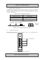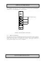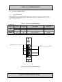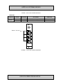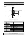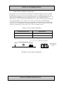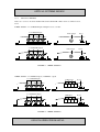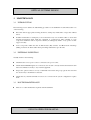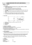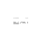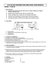
1
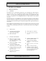
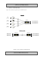
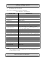
OPERATOR MANUAL
OSD8224 SERIES
3G HD/SDI TX/RX
FIBER OPTIC TRANSMISSION SYSTEM
OPTICAL SYSTEMS DESIGN
INDEX 1
1
TECHNICAL SUMMARY ........................................................................................................................ 4
BRIEF DESCRIPTION ............................................................................................................................ 4
OVERVIEW ........................................................................................................................................ 4
APPLICATIONS ................................................................................................................................. 4
FEATURES AND BENEFITS ............................................................................................................ 4
TYPICAL CONFIGURATION ................................................................................................................ 5
TECHNICAL SPECIFICATIONS ........................................................................................................... 6
1.1
1.1.1
1.1.2
1.1.3
1.2
1.3
2
INSTALLATION AND OPERATION ..................................................................................................... 7
2.1
2.2
2.2.1
2.2.2
2.2.3
2.2.4
2.2.5
2.2.6
2.3
2.3.1
2.3.2
2.3.3
2.3.4
2.3.5
3
INTRODUCTION .................................................................................................................................... 7
INSTALLATION ..................................................................................................................................... 7
CABLING............................................................................................................................................ 7
WARNING AND PRECAUTIONS .................................................................................................... 7
OSD8224 DRAWINGS AND DIMENSIONS .................................................................................... 8
POWER SUPPLY CONNECTIONS ................................................................................................... 9
3G HD/SDI CONNECTIONS ............................................................................................................. 9
OPTICAL CONNECTIONS .............................................................................................................. 10
OSD8224 OPERATION ......................................................................................................................... 11
SWITCH SETTINGS ........................................................................................................................ 11
OSD8224T AND OSD8224R INDICATORS ................................................................................... 13
NETWORK MANAGEMENT SYSTEM (NMS) ............................................................................. 15
OSD8224 VARIANTS ...................................................................................................................... 16
FITTING SFP CONNECTORS ......................................................................................................... 17
MAINTENANCE ...................................................................................................................................... 18
3.1
3.2
3.3
4
INTRODUCTION .................................................................................................................................. 18
EXTERNAL INSPECTION ................................................................................................................... 18
ROUTINE MAINTENANCE................................................................................................................. 18
WARRANTY ............................................................................................................................................ 19
4.1
4.2
4.2.1
4.2.2
4.2.3
4.2.4
WARRANTY PERIOD .......................................................................................................................... 19
REPAIRS ............................................................................................................................................... 19
WARRANTY REPAIRS ................................................................................................................... 19
OUT-OF-WARRANTY REPAIRS ................................................................................................... 19
SITE REPAIRS.................................................................................................................................. 19
EXCLUSIONS................................................................................................................................... 19
FIGURE 1: OSD8224 TYPICAL CONFIGURATIONS ........................................................................................... 5
FIGURE 2: OSD8224 MOUNTING DIMENSIONS ................................................................................................ 8
FIGURE 3: OSD8224 POWER SUPPLY CONNECTIONS ..................................................................................... 9
FIGURE 4: OSD8224T VIDEO CONNECTIONS.................................................................................................... 9
FIGURE 5: OSD8224R VIDEO CONNECTIONS ................................................................................................. 10
FIGURE 6: OSD8224T SWITCH SETTINGS ........................................................................................................ 11
FIGURE 7: OSD8224R SWITCH SETTINGS ........................................................................................................ 12
FIGURE 8: OSD8224T LED INDICATORS .......................................................................................................... 13
FIGURE 9: OSD8224R LED INDICATORS .......................................................................................................... 14
FIGURE 10: OSD8224 NMS CONNECTIONS ...................................................................................................... 15
FIGURE 11: 1-FIBER VERSION ........................................................................................................................... 16
FIGURE 12: 4-FIBER VERSION ........................................................................................................................... 16
FIGURE 13: CARD VERSION ............................................................................................................................... 17
FIGURE 14: FITTING/REMOVING SFP CONNECTORS ................................................................................... 17
TABLE 1: TECHNICAL SPECIFICATIONS ........................................................................................................... 6
TABLE 2: OSD8224 DC POWER CONNECTION .................................................................................................. 9
TABLE 3: OSD8224T SWITCH SETTINGS ......................................................................................................... 11
TABLE 4: OSD8224R SWITCH SETTINGS ......................................................................................................... 12
TABLE 5: OSD8224T LED INDICATORS ............................................................................................................ 13
TABLE 6: OSD8224R FRONT PANEL INDICATOR FUNCTION...................................................................... 14
TABLE 7: OSD8224 NMS CONNECTION ........................................................................................................... 15
DOC ID: 10112503
PAGE 3
OSD8224 OPERATOR MANUAL
OPTICAL SYSTEMS DESIGN
1
TECHNICAL SUMMARY
1.1
BRIEF DESCRIPTION
1.1.1
OVERVIEW
The OSD8224 series is a high-quality 4-channel fiber optic serial digital video (SDI) transmission
system. The system consists of the OSD8224T transmitter and the OSD8224R receiver, which are
designed to be used as a pair to reliably transport either four SDI over four individual fibers using
1310nm or over one fiber using 1510, 1530, 1550, 1570nm wavelengths. The OSD8224 pair is suitable
for point to point applications or four 3G HD/SDI transmitters to a single 4-channel receiver using the
OSD8220T.
The OSD8224T accepts four 3G HD/SDI video input signals. Each channel has an SDI equalizer to
effectively compensate for coaxial cable losses and is optimised for high quality cable such as Belden
1694A cable. This allows flexibility for permanent and temporary installations when the SDI source is
some distance away from the unit. The user can disable the equaliser with a toggle switch mounted on
the front panel.
Both the OSD8224T and OSD8224R have built-in user bypassable automatic reclocking. The units will
lock at 270Mbps, 1.485Gbps and 2.97Gbps. The user can disable the reclocker with a toggle switch
mounted on the front panel. This allows the units to operate with other data rates from 19.4Mbps to
2.97Gbps
1.1.2
▲
▲
1.1.3
▲
▲
▲
▲
▲
APPLICATIONS
Any digital broadcast application
such as studio signal routing and
temporary OB or studio links
▲
▲
Remote camera links
FEATURES AND BENEFITS
Built in user bypassable automatic
reclocking at 270Mbps, 1.485Gbps
and 2.97Gbps with indication of data
rate on each channel
Operates from 19.4Mbps to 2.97Gbps
in non-reclocked mode
Compatible with SMPTE 310M,
292M, 259M, 297M, 372M and 424M
Automatic equalisation of up to 350m
@ 270Mbps and 70m @ 2.97Gbps of
Belden 1694A cable
Compatable with OSD Network
Management System
▲
▲
▲
▲
▲
Campus digital video distribution
Very high performance surveillance
networks
Available in 1310nm, 1550nm and all
eighteen CWDM wavelengths
Available with built in CWDM
multiplexer for 4-channel single fiber
operation
Capable of operation over more than
50km
Immune to pathological signals
Available as a single slot width card
which plugs into OSD’s standard 19”
chassis or as a rugged module suitable
for both permanent and temporary
throwdown applications.
DOC ID: 10112503
PAGE 4
OSD8224 OPERATOR MANUAL
OPTICAL SYSTEMS DESIGN
1.2
TYPICAL CONFIGURATION
Figure 1 below indicates the typical set-ups for an OSD8224 system.
4-Tx to 1-Rx
OSD8220T
HD/SDI
signal source
1 fiber
OSD8220T
HD/SDI
signal source
OSD8224R
1 fiber
OSD8220T
HD/SDI
signal source
Monitor with HD/SDI interface
Monitor with HD/SDI interface
Monitor with HD/SDI interface
Monitor with HD/SDI interface
1 fiber
1 fiber
OSD8220T
HD/SDI
signal source
4-Channel on 1-Fiber
OSD8224T.CW
HD/SDI signal source
HD/SDI signal source
HD/SDI signal source
HD/SDI signal source
OSD8224R.CW
Monitor with HD/SDI interface
Monitor with HD/SDI interface
Monitor with HD/SDI interface
Monitor with HD/SDI interface
1 fiber
`
FIGURE 1: OSD8224 TYPICAL CONFIGURATIONS
DOC ID: 10112503
PAGE 5
OSD8224 OPERATOR MANUAL
OPTICAL SYSTEMS DESIGN
1.3
TECHNICAL SPECIFICATIONS
Table 1 below provides Technical Specifications for the OSD8224.
TABLE 1: TECHNICAL SPECIFICATIONS
SPECIFICATION
PERFORMANCE
Number of Channels
4
Input/Output Impedance
75Ω
Input/Output Levels
800mVpp nominal
SDI Connectors
350m @ 270Mbps
140m @ 1.485Gbps
70m @ 2.97Gps
BNC female sockets
Power Connector
4 way terminal block on module, DB9 on card
Number of Fibers
Fiber Type
4 for standard unit, 1 for CWDM unit
Singlemode is standard
1310nm ±30nm (1550nm and all 18 CWDM wavelengths are
optionally available). Standard 4-Channel CWDM module operates
on 1510, 1530, 1550 and 1570nm)
Coax Equalization
Transmitter Wavelength
Transmitter Coupled Power
-5 to -0dBm (0dBm and +2dBm are optional)
Receiver Operating Wavelength
1200 to 1600nm
Receiver Sensitivity
<-18dBm for 1x10⁻⁹ Bit Error Rate
Receiver Saturation
>13dB at 1310nm (>30km of singlemode fiber)
>20dB at 1550nm with +2dBm laser (>60km on singlemode fiber)
>0dBm
Optical Connector
LC Standard. FC and ST are optional for the 1-fiber CWDM unit
Power Requirements
+5 to 20VDC @ 4VA
Dimensions of 4-fiber Module (mm)
114W x 105D x 32H
Weight of 4-fiber Module
350g
Dimensions of 1-fiber Module (mm)
114W x 174D x 32H
Weight of 1-fiber Module
500g
Dimensions of Card (mm)
25W x 208D x 100H
Operating Temperature
-20°C to +65°C
Relative Humidity
0 to 95% non-condensing
Chassis Current Consumption (CCC)
0.3 Amp
Optical Link Budget and distances
102822405
NOTES:
*Other combinations of laser types and optical levels, receiver types and sensitivity levels are
possible. Contact OSD for details.
DOC ID: 10112503
PAGE 6
OSD8224 OPERATOR MANUAL
OPTICAL SYSTEMS DESIGN
2
INSTALLATION AND OPERATION
2.1
INTRODUCTION
This section outlines the methods required to install and operate the OSD8224T and OSD8224R
successfully. It should be studied carefully if damage to the equipment or poor results are to be avoided.
This equipment has been fully tested prior to dispatch and is ready for immediate operation. However it
is advisable to check for external transportation damage before operation. If damage is evident, return
the unit with the packaging to your supplier immediately.
2.2
INSTALLATION
2.2.1
CABLING
Shielded cables should be used on all cabling to provide protection from external electrical events such
as lighting, and switching transients etc. which may cause damage to the unit. All cable shielding must
be grounded at a convenient ground point.
2.2.2
WARNING AND PRECAUTIONS
▲
ELECTROMAGNETIC COMPATIBILITY
WARNING: This is a Class A product. In a domestic environment this product may cause radio
interference in which case the user may be required to take adequate measures.
▲
OPTICAL OUTPUT OPERATION
WARNING: Laser Safety: Class 1 Laser Product per IEC/EN 60825-1:20011 standard.
Class 1
The OSD8224 is a Class 1 laser product.
PRECAUTIONS
▲
▲
▲
▲
▲
All service personnel should be provided training as to the hazards of direct viewing of laser
radiation and of the precautionary measures during servicing of equipment
Areas where laser products are installed should be restricted in access to trained service
personnel only and appropriate warning signs posted in the work area.
All laser apertures should be covered by protective covers when not connected to optical
fibers. Never leave outputs uncovered.
Laser equipment should be positioned above or below eye level where possible. Apertures
should be positioned away from personnel.
Protective eyewear should be worn in the vicinity of laser equipment.
DOC ID: 10112503
PAGE 7
OSD8224 OPERATOR MANUAL
OPTICAL SYSTEMS DESIGN
2.2.3
OSD8224 DRAWINGS AND DIMENSIONS
The OSD8224 module versions are designed to be mounted on an even surface and to be secured by
means of M4 or smaller screws. The OSD8224 card versions are designed to be inserted into a chassis
and secured by means of captivated screws.
1-Fiber Module
32
118
DETAIL A
138
121
Ø8.5
8.0
R2.1
8.0
R2.1
174
4-Fiber Module
32
50
DETAIL A
138
121
8.0
R2.1
R2.1
105
25
100
Card Version
208
FIGURE 2: OSD8224 MOUNTING DIMENSIONS
DOC ID: 10112503
PAGE 8
OSD8224 OPERATOR MANUAL
Ø8.5
8.0
OPTICAL SYSTEMS DESIGN
2.2.4
POWER SUPPLY CONNECTIONS
The OSD8224T and OSD8224R requires external DC power. The voltage range is +5 to 20VDC. For
module versions, power should be connected to the power socket located on the rear panel of the units
and applied as indicated below. For card versions, power is supplied via the DB9 connector from the
OSD350N or OSD370N chassis.
TABLE 2: OSD8224 DC POWER CONNECTION
External Power Pin
Specification
Pin 1
Ground or 0V
Pin 2
+5 to 20VDC
Power Connector
4
3
2
1
Note: Pins 3 &
4 are used for
NMS
1-Fiber version shown
FIGURE 3: OSD8224 POWER SUPPLY CONNECTIONS
2.2.5
3G HD/SDI CONNECTIONS
The 3G HD/SDI video-input signals (eg. from camera) is connected to the 3G HD/SDI BNC input
connectors on the OSD8224T. Note: Card Version Shown.
3G HD/SDI Inputs
FIGURE 4: OSD8224T VIDEO CONNECTIONS
DOC ID: 10112503
PAGE 9
OSD8224 OPERATOR MANUAL
OPTICAL SYSTEMS DESIGN
The 3G HD/SDI output signal (eg. to monitor equipment) is connected from the 3G HD/SDI BNC
output connectors on the OSD8224R. Note: Card Version Shown.
3G HD/SDI Outputs
FIGURE 5: OSD8224R VIDEO CONNECTIONS
2.2.6
OPTICAL CONNECTIONS
The optical fiber cable must be terminated with the appropriate optical connector. Before connection,
inspect the ends of the connectors to ensure that no dust or dirt is present as it could contaminate the
modem connector and result in poor performance. If it is necessary to clean the cable connectors, use
isopropyl alcohol and lint free tissue to remove contamination.
DOC ID: 10112503
PAGE 10
OSD8224 OPERATOR MANUAL
OPTICAL SYSTEMS DESIGN
2.3
OSD8224 OPERATION
2.3.1
SWITCH SETTINGS
The OSD8224T has Automatic Equalizer and Reclocker switches located on the front panel. The
OSD8224R has only the Reclocker switch. The default setting upon shipment is in the “on” position.
Note: Card Version Shown.
TABLE 3: OSD8224T SWITCH SETTINGS
OSD8224T
SWITCH
EQ
RCLK
STATE
POSITION
FUNCTION
OFF
ON
OFF
ON
DOWN
UP
DOWN
UP
Automatic Equalizer Off
Automatic Equalizer On
Reclocker Bypassed
Reclocker Enabled
DEFAULT
default*
default*
RCLK – Reclocker
EQ – Automatic Equalizer
FIGURE 6: OSD8224T SWITCH SETTINGS
DOC ID: 10112503
PAGE 11
OSD8224 OPERATOR MANUAL
OPTICAL SYSTEMS DESIGN
TABLE 4: OSD8224R SWITCH SETTINGS
OSD8224R
SWITCH
STATE
POSITION
FUNCTION
DEFAULT
RCLK
OFF
ON
DOWN
UP
Reclocker Bypassed
Reclocker Enabled
default*
RCLK – Reclocker
FIGURE 7: OSD8224R SWITCH SETTINGS
DOC ID: 10112503
PAGE 12
OSD8224 OPERATOR MANUAL
OPTICAL SYSTEMS DESIGN
2.3.2
OSD8224T AND OSD8224R INDICATORS
OSD8224T
CD - Carrier Detect
LF – Laser Fail
LD – Lock Detect
Data Rate
FIGURE 8: OSD8224T LED INDICATORS
TABLE 5: OSD8224T LED INDICATORS
LABEL
INDICATOR
CD
Carrier Detect
COLOUR
Red
Green
Off
LD
Lock Detect
LF
Laser
Rate
Data Rate
Green
FUNCTION
SDI source is off or unplugged
Carrier Detected
Reclocker not locked or reclocker in bypass mode.
Reclocker is locked
Red (Blink)
Faulty Laser / No SFP
Off
Laser OK / SFP fitted
Slow
(1 blink/sec)
Med
(2 blinks/sec)
Fast
(3 blinks/sec)
SD Input
HD Input
3G Input
DOC ID: 10112503
PAGE 13
OSD8224 OPERATOR MANUAL
OPTICAL SYSTEMS DESIGN
OSD8224R
Rx – Receive Signal
LD – Lock Detect
Data Rate
FIGURE 9: OSD8224R LED INDICATORS
TABLE 6: OSD8224R FRONT PANEL INDICATOR FUNCTION
LABEL
INDICATOR
COLOUR
Off
LD
Lock Detect
Green
Red
RX
Receive
Signal
Blinking
(R/G)
Green
Rate
Data Rate
Slow
(1 blink/sec)
Med
(2 blinks/Sec)
Fast
(3 blinks/sec)
FUNCTION
Reclocker not locked or reclocker in bypass mode.
Reclocker is locked
No optical signal
SFP not installed or engaged properly
Optical signal present
SD Signal
HD Signal
3G Signal
DOC ID: 10112503
PAGE 14
OSD8224 OPERATOR MANUAL
OPTICAL SYSTEMS DESIGN
2.3.3
NETWORK MANAGEMENT SYSTEM (NMS)
The OSD8224 can be optionally fitted/enabled with the OSD Network Management System (NMS).
The NMS allows the user control of various parameters of each node within the network. Any video
and/or data channels from any node can be monitored at the receiver. The OSD NMS is designed to be
implemented in an SNMP (Simple Network Management Protocol) or Web Browser Based
environment, in order to remotely check running status or to configure an OSD optical modem product.
The OSD8224R NMS version is designed to be used in conjunction with the OSD8020 NMS
concentrator card which in turn utilizes either the OSD350N or OSD370N chassis. For detailed NMS
operation refer to the OSD8020 user manual. The NMS connections are via the DB9 connector. The
module version utilizes pins 3 and 4 of the power connector for NMS operation.
TABLE 7: OSD8224 NMS CONNECTION
External Power Pin
Specification
Pin 3
NMS +
Pin 4
NMS -
Power Connector
4
3
2
1
Note: Pins 1 &
2 are used for
Power
1-Fiber version shown
FIGURE 10: OSD8224 NMS CONNECTIONS
DOC ID: 10112503
PAGE 15
OSD8224 OPERATOR MANUAL
OPTICAL SYSTEMS DESIGN
2.3.4
OSD8224 VARIANTS
There are 3 versions of both the OSD8224T and the OSD8224R: 1-Fiber Version, 4-Fiber Version,
Card.
1-Fiber Version – 4 x 3G HD/SDI inputs multiplexed onto one fiber
4 x 3G HD/SGI Inputs
1-Fiber Output
OSD8224T Front Panel View
OSD8224T Rear Panel View
4 x 3G HD/SDI Outputs
OSD8224R Front Panel View
Power
1-Fiber Input
Power
OSD8224R Rear Panel View
FIGURE 11: 1-FIBER VERSION
4-Fiber Version – 4 x SD/HD/3G inputs, 4 SFP Fiber outputs
4 x 3G HD/SDI Inputs
OSD8224T Front Panel View
4-SFP Output
OSD8224T Rear Panel View
4 x 3G HD/SDI Outputs
OSD8224R Front Panel View
Power
4-SFP Input
Power
OSD8224R Rear Panel View
FIGURE 12: 4-FIBER VERSION
DOC ID: 10112503
PAGE 16
OSD8224 OPERATOR MANUAL
OPTICAL SYSTEMS DESIGN
Card Version – 4 x 3G HD/SDI inputs multiplexed onto one fiber
Optical Output
Optical Input
4 x SD/HD/3G Inputs
4 x SD/HD/3G Outputs
OSD8224T Front Panel View
OSD8224R Front Panel View
FIGURE 13: CARD VERSION
2.3.5
FITTING SFP CONNECTORS
Care should be taken when inserting/removing the SFP connectors from the SFP port as SFP modules
are Electrostatic (ES) sensitive and Electrostatic Discharge (ESD) precautions should be taken when
installing. Ensure that the SFP is fully engaged and latched into position.
Inserting SFP – Ensure that the SFP lever is in the locked position and insert into appropriate SFP
port. Gently push the SFP until it locks into place. Remove plastic/rubber dust cap and fit appropriate
fiber cable.
Removing SFP – Remove fiber connector. Pull the SFP lever down to unlock SFP from housing.
Using the lever, gently pull the SFP out.
2
1
Fiber SFP
Inserting
SFP
Removing
SFP
FIGURE 14: FITTING/REMOVING SFP CONNECTORS
DOC ID: 10112503
PAGE 17
OSD8224 OPERATOR MANUAL
OPTICAL SYSTEMS DESIGN
3
3.1
MAINTENANCE
INTRODUCTION
The following section outlines the fault-finding procedure for the OSD8224 modems. Please take note
of the following:
▲
▲
▲
3.2
Personnel without appropriate training should not attempt any maintenance except that outlined
below.
If further maintenance is attempted you are warned that every care should be taken to ensure that
internal measurements made while the equipment is operational are taken carefully as some
components within the unit are expensive and may be damaged by failure of any portion of their
support circuitry.
Some components within the unit are Electrostatic (ES) sensitive and Electrostatic Discharge
(ESD) precautions should be taken when performing maintenance upon the unit.
EXTERNAL INSPECTION
Visually check for the following:
▲
▲
▲
▲
3.3
▲
Check that the correct power source is connected to the power socket.
Check that the HD/SDI signals are connected to the modem correctly and that the distant modem
has been terminated correctly to any external equipment.
Inspect the optical connectors for any contamination and clean using isopropyl alcohol and a lint
free tissue if any contamination is detected.
Check that any external termination resistors are connected if the system configuration requires
them.
ROUTINE MAINTENANCE
There is no routine maintenance required with the OSD8224.
DOC ID: 10112503
PAGE 18
OSD8224 OPERATOR MANUAL
OPTICAL SYSTEMS DESIGN
4
WARRANTY
Thank you for purchasing equipment designed, manufactured and serviced by Optical Systems Design
(OSD). OSD warrants that at the time of shipment, its products are free from defects in material and
workmanship and conforms to specifications. Our Warranty conditions are outlined below:
4.1
WARRANTY PERIOD
For warranty period, please call your local OSD distributor.
4.2
REPAIRS
Optical Systems Design reserves the right to repair or replace faulty modules/units. Please obtain a
“Return Material Authorisation” (RMA) form and number before returning goods.
Goods must be returned in adequate packing material to Optical Systems Design, Warriewood or its
nominated authorised representative, for all repairs.
4.2.1
WARRANTY REPAIRS
Return shipments to OSD shall be at customer's expense and freight back to the customer will be at
OSD expense.
4.2.2
OUT-OF-WARRANTY REPAIRS
OSD reserves the right to repair or replace any faulty goods. Freight costs and insurance for both
journeys are met by the user. All equipment repaired by OSD will have a 3-Month Warranty from the
date of dispatch.
4.2.3
SITE REPAIRS
By agreement site repairs may be undertaken for which out of pocket, hotel and travel expenses will be
charged.
4.2.4
EXCLUSIONS
This warranty does not apply to defects caused by unauthorized modifications, misuse, abuse or
transport damage to the equipment. All modifications to OSD’s standard product will need written
authorization and will be charged at normal repair rates. All modifications are to be carried out by OSD
Technicians. Warranty is void if unauthorized removal and/or tampering with serial number and/or
labels is evident.
DOC ID: 10112503
PAGE 19
OSD8224 OPERATOR MANUAL
Optical Systems Design Pty. Ltd.
7/1 Vuko Pl. Warriewood 2102
P.O. Box 891 Mona Vale
N.S.W. Australia 2103
Telephone: +61 2 9913 8540
Facsimile: +61 2 9913 8735
Email: [email protected]
Web Site: www.osd.com.au
OPTIC L
SYSTEMS
DESIGN
PTY LTD
A.B.N. 83 003 020 504
Printed in Australia