1
Innovative Vehicle Electronics Systems
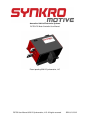
DC750 DC Motor Controller User Manual
Patent pending ©2012 Synkromotive, LLC
DC750 User Manual ©2012 Synkromotive, LLC. All rights reserved.
REV 6/11/2012
Introduction
2
Integrated Safety Features
3
Physical Installation
4
High Voltage (Traction Pack) Wiring
6
Connector Wiring Overview
8
Contactors and Safety
9
Basic Wiring
10
Single Reversing Contactor Wiring
11
Multiple Reversing Contactor Wiring
12
Synkromotive CAN communication
13
Using the Synkromotive Graphical User Interface (SMI)
14
Main Panel / Configuration Tab:
15
Main Panel / Stats Tab and DC Controller / Stats Tab:
16
DC Controller / User Tab:
17
DC Controller / OEM Tab:
18
Main Panel / Custom Gauges Tab:
19
Main Panel / Custom Bars Tab:
20
DC Controller / Flash Tab:
21
Firmware update:
22
Automated Throttle Pot Calibration Process
25
PC Data Logging
26
DC750 Specifications
28
Warranty
29
Contact Information:
31
DC750 User Manual ©2012 Synkromotive, LLC. All rights reserved.
Page 1
Introduction
Thank you for purchasing the Synkromotive DC750
controller. This controller has been designed to be
one of the most versatile DC motor controllers on
the market. It can be used in all sizes of on-road
and off-road electric vehicles utilizing systems from
24~192 volts. Although the controller is optimized
to regularly provide 750 amp accelerations the
controller is fully adjustable allowing short duration
current limits up to 900 amps.
The DC750 has a patented design feature which
reduces power loss; it switches faster and more
efficiently thereby producing less heat. However
some cooling is still required. On a vehicle less weight means better performance and more
range so the DC750 needed a cooling scheme that was simple and light weight. In a liquid
cooled system the coolant must move hot liquid from the heat source to a radiator which is
either fan cooled or exposed to a large volume of cold air. Ultimately this means even liquid
cooling still requires the excess heat transfer to the air. So rather than add the extra weight and
plumbing required simply to move the heat to a different location to be fan cooled the DC750
cuts to the chase and uses an aggressive forced air design to effectively transfer excess heat
directly to the air.
The DC750 is high side topology which offers reduced motor and brush corrosion risk over less
expensive controllers. Also the power stage is fully isolated from the control wiring thereby
reducing shock hazard. The CAN communication system is also fully isolated to ensure noise
free real time communication. This feature rarely exists on other controllers. The case is also
fully isolated from all internal circuitry making it easier to install without adding additional
mounting insulators.
Another feature that sets the DC750 apart is the user interface. Advanced microprocessor
technology allows reprogramming or recalibration of the system while installed, via the
Synkromotive interface (SMI). The Synkromotive interface also allows the user to view data in
real time, in both text and graphical formats. In addition, the on-board flash memory provides a
nonvolatile backup of all system parameters and settings.
The DC750 has built in +12 volt output contactor coil drivers that allow the user to confugure the
controller to work in the various common electric vehicle configurations. Unlike software only
systems in some cars all contactor outputs can be “manually overridden” and disabled by simply
turning off the “key” and thereby removing power to contactors. Also a built pre-charging system
is in place to extend the life of the main contactor as well as provides a pre-power up safety
check.
These are a just a few of the many design details that went into the Synkromotive DC750 motor
controller.
DC750 User Manual ©2012 Synkromotive, LLC. All rights reserved.
Page 2
Integrated Safety Features
The DC750 contains an intelligent, multiple redundant failsafe system to provide a high degree
of safety. The vehicle will shut down on any fault as a precaution.
Safe Start:
The start sequence begins when the ignition switch is turned on. Upon every power up, the
DC750 tests for shorts and looks at various internal and external control points, such as
voltages and temperatures. The throttle must be in a zero state before the drive mode is
enabled to prevent unintended movement. Low traction pack voltage also prevents vehicle
operation.
Contactor Control:
The DC750 will activate the contactor when the system successfully completes the safe start
sequence. The contactor will remain enabled unless there is a critical fault or if the ignition
switch is turned off. The contactor drivers and the pre-charge circuit are all built into the DC750,
eliminating the need for any external accessories on the contactor. In addition the contactor
control is powered by the key switch thereby providing a manual override disconnect in the
event of a runaway condition.
Open Throttle Input:
The DC750 will fault if the throttle signal goes out of range due to faulty wiring or hardware. This
also is to prevent a runaway condition.
Priority Braking:
The DC750 assigns priority to the brake in the event that both the brake and throttle are applied
simultaneously.
Direction Change Lockout:
The DC750 will not allow the vehicle direction to be changed via a reversing contactor unless
the vehicle has come to a full stop and the throttle is at zero. Only then will the DC750 enable
the reversing contactor.
Reverse Power Limit:
The DC750 allows for separate speed when in reverse which is useful with vehicles not using a
mechanically reversing transmission.
Temperature Monitoring:
The DC750 will limit the current output of the controller in a linear fashion as the internal
temperature rises above the normal safe level.
Battery Voltage Monitoring:
The DC750 will limit the current output of the controller when the traction pack voltage is low.
DC750 User Manual ©2012 Synkromotive, LLC. All rights reserved.
Page 3
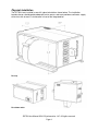
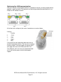
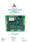
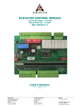
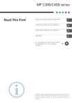
Physical Installation
The DC750 is best installed in one of 3 typical orientations shown below. The installation
location chosen should provide adequate service access and must provide a continuous supply
of fresh air with at least 4” of clearance in front of the integrated fan.
Face up
Face down under
Face out on Firewall
DC750 User Manual ©2012 Synkromotive, LLC. All rights reserved.
Page 4
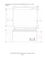
Physical Dimensions in Millimeters (Base Flange Mounting Holes Use ¼” or M6
Hardware):
DC750 User Manual ©2012 Synkromotive, LLC. All rights reserved.
Page 5
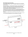
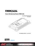
High Voltage (Traction Pack) Wiring
Using a suitable voltage meter, ensure that the traction pack voltage source is disconnected
prior to making any connections. Always use insulated tools and gloves while working with high
voltage connections.
When routing the cables, it is advised to keep the motor leads as short as possible to minimize
electrical noise and power losses. Always run high voltage cables parallel with other high
voltage cables. Avoid crossing high voltage cables or attaching control wiring to the power
wiring. Always protect the cables against damage from fraying by keeping them away from any
sharp surfaces and by using bushings at any penetration.
The holes provided in the buss bars are designed for 5/16” or M8 hardware. Each hole is
designed for only one lug connection. Always install the lug with the flat side against the buss
bar for maximum surface contact. Use a stainless steel nut and bolt combination with a split lock
washer and provide enough torque to make a lasting connection, but take care not to over
tighten. Always use a backup wrench when tightening these bolts to keep any stress off of the
buss bars.
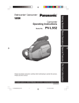
The DC750’s high side design allows for both motor negative and battery negative to share the
same connection post although bolt holes for each are provided as shown below.
DC750 User Manual ©2012 Synkromotive, LLC. All rights reserved.
Page 6
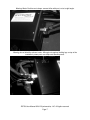
Warning: Motor Positive must always connect inline with post, not at a right angle.
Warning: do not block the exhaust vents. Although not required, bolting lugs on top of the
controller’s power posts can help avoid blocking vents.
DC750 User Manual ©2012 Synkromotive, LLC. All rights reserved.
Page 7
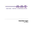
Connector Wiring Overview
External control wiring connections are made at the 23 position AMPSEAL connector located on
the side of the DC750. A prewired assembly of un-terminated leads is provided with the DC750
to assist in the final wiring. The minimum required wiring is noted in bold; all other wiring is
recommended but is not required to enter drive mode.
The connector pin functions are as follows:
Speed Sensor Negative
(-)
Sensor 3
+12v Input
Sensor 2
+12v Input
Vehicle Ground
(-)
Vehicle Ground
(-)
Contactor Return
(-)
Contactor Return
(-)
Indicator
+12v Output
Accelerator Return
(-)
Sensor Supply
+12v Output
Forward Switch
+12v Input
Reverse Switch
+12v Input
Charge Control
+12v Input
Constant Power
+12v Input
Reverse Contactor
+12v Output
Battery Pack Positive
0~200v Input
Accelerator Supply
+5v Output
Speed Sensor 1
+12v Input
Accelerator Input
0~5v Input
Brake Switch
+12v Input
Ignition On
+12v Input
Main Contactor
+12v Output
Forward Contactor
+12v Output
The Synkromotive Controller Harness wires are typically colored based on their type: (input,
output, negative, etc.)
When you start your installation it is helpful to separate out and group the 3 Accelerator wires
(#9, #17, and #19). Then group the 3 wires to the main contactor (#22, #6, and #16). Next group
the 3 speed sensor wires (#10, #18, #1). This leaves the vehicle interface wires (brake, reverse,
ignition, etc) easier to sort through.
DC750 User Manual ©2012 Synkromotive, LLC. All rights reserved.
Page 8
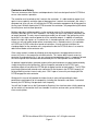
Contactors and Safety
There are numerous other features and dependencies that have designed into the DC750 that
ensure safe seamless operation.
The controller must be wired so that it controls the contactors. It is able to able to protect itself
against reverse polarity and other types of damage when it controls the contactors. No safety is
compromised since you can still override the DC750's contactor engagement by killing power to
the key input. Without allowing the DC750 to control the contactors, the programming will detect
the wiring error and not allow operation.
Multiple redundant safeties are built in to the contactor controls. For example the ignition key
inherently overrides the DC750 in hardware. You simply turn off the key and the contactors are
no longer powered. The only manual contactor override you will need is the ignition key which
by design is the single source of power for all the contactor outputs. In addition all contactor
outputs are high side signals so if a control wire is shorted to ground such as in an installation
error or an unusual fender bender where a contactor wire is shorted to chassis, the contactor
will OPEN not CLOSE unlike other brands of controllers. Also for easing installation the
clamping diodes for the contactor coils are prewired inside the DC750 so there is no need to
add external diodes at the contactor coils.
Other safety controls include not allowing reversing contactors to engage when excessive
current still exists in the motor after a throttle release. This feature both extends reversing
contactor life and controller life. If you are using reversing contactors then it is important for both
the reversing and main contactors be controlled by the DC750 to perform these functions.
An optional negative battery contactor and any other pack contactors are best implemented by
simply wiring them to the ignition key. Wiring a negative contactor to the DC750’s main
contactor output will not allow the DC750s pre-charging function to work properly. The DC750s
pre-charging feature both extends main contactor life and improves the DC750’s longevity all
while performing various internal safety tests. ONLY upon a successful pre-charging will the
DC750 engage the main contactor.
Wiring per this manual will provide the highest level of safety while providing the best
performance and longevity of all components including the contactors and motor. If not wired
correctly the DC750 may not operate or fault frequently.
You will find it helpful to use the Synkromotive Graphical User Interface when initially powering
up the vehicle; all connection faults are viewable in real time and can alert you to the wiring
errors much quicker.
DC750 User Manual ©2012 Synkromotive, LLC. All rights reserved.
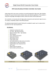
Page 9
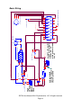
High
Voltage
Battery
Pack
+
-
DC/DC conv erter
DC/DC enable
using standard
common negative
chassis ground
BATT-
BATT+
DC/DC RELAY
+13.8
GND
Motor+
12 v olt 20 AH
Off
Continuous Power
Accessory
Engine ON
Start
S2
using 12 volt battery
allows hazard lights,
clocks, etc... to
work as normal with
key off
Continuous Power f or hazards lights etc...
Ignition Key Sw itch
MAIN ON/OFF
15
180 v olt 200 AH
10a FUSE
23
8
ANDERSON1
battery serv ice disconnect
22
7
Motor+
21
6
BATT+
S1
f rom Brake Light+
3
2
1
motor speed sensor
OUT
GND
Throttle Position Sensor
12
Main contactor
SYNKRO DC controller Connector
11
BATT-
10
1/2 amp FUSE
20
5
+Vs
9
SYNKRO DC controller
19
4
A1
18
3
A2
16
series DC MOTOR
17
2
Page 10
1
battery pack v oltage sense and precharge
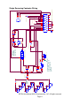
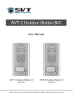
Basic Wiring
DC750 User Manual ©2012 Synkromotive, LLC. All rights reserved.
13
14
+
+
-
BP15
12 VOLT
+
BP19
12 VOLT
+
-
+
BP11
12 VOLT
BP16
12 VOLT
BP20
12 VOLT
battery
pack
+
BP13
12 VOLT
BP17
12 VOLT
BP21
12 VOLT
DC/DC conv erter
+13.8
GND
Enable
using standard 12 volt
battery with common
negative chassis
ground
BATT-
BATT+
RELAY DC/DC enable
K5
FUSE
Main contactor
Motor-
SYNKRO DC controller
-
-
-
-
+
+
+
BP9
12 VOLT
ANDERSON1
battery serv ice disconnect
BP18
12v 7ah ~ 20ah
+
-
-
-
-
-
-
+
+
+
Page 11
-
BATT+
S2
S1
Optional DC/DC enable
Off
Accessory
Engine ON
Start
Indicator
MAIN ON/OFF
Optional manual start mode
Continuous Power
series DC MOTOR
Ignition Key Sw itch
Motor+
23
8
1/2 amp FUSE
22
7
BP7
12 VOLT
21
6
BATT-
OUT
3
2
motor speed sensor
P1
GND
1
f rom Rev erse light+
f rom Brake Light+
Throttle Position Sensor
P2
SYNKRO DC controller Connector
12
BP5
12 VOLT
11
A2
19
4
A1
20
5
+Vs
10
BP4
12 VOLT
18
3
K3
Rev ersing SPDT
9
K2
Forward SPDT
17
2
Main FUSE
16
1
Albright
reversing
contactors
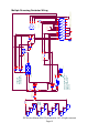
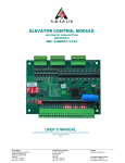
Single Reversing Contactor Wiring
DC750 User Manual ©2012 Synkromotive, LLC. All rights reserved.
13
14
15
+
BP4
12 VOLT
+
BP7
12 VOLT
+
BP11
12 VOLT
+
+
BP5
12 VOLT
BP8
12 VOLT
BP12
12 VOLT
battery
pack
BP6
12 VOLT
BP9
12 VOLT
BP13
12 VOLT
DC/DC conv erter
+13.8
GND
Enable
using standard 12 volt
battery with common
negative chassis
ground
BATT-
BATT+
RELAY DC/DC enable
K6
FUSE
Motor-
SYNKRO DC controller
BP10
12v 7ah ~ 20ah
-
-
-
-
-
+
+
+
Main contactor
+
-
-
+
+
+
+
-
-
BP3
12 VOLT
ANDERSON1
battery serv ice disconnect
Off
Accessory
Engine ON
Start
S1
Optional DC/DC enable
Ignition Key Sw itch
S2
Rev erse contactor1
Continuous Power
Indicator
MAIN ON/OFF
Optional manual start mode
Forward contactor1
15
-
-
-
-
BP2
12 VOLT
23
8
Motor+
22
7
BATT+
OUT
GND
+Vs
3
2
1
Throttle Position Sensor
motor speed sensor
P1
f rom Rev erse light+
f rom Brake Light+
13
1/2 amp FUSE
21
6
BATT-
12
Main FUSE
20
5
BP1
12 VOLT
16
P2
SYNKRO DC controller Connector
11
A2
19
4
A1
10
series DC MOTOR
18
3
Rev erse contactor2
9
Forward contactor2
17
2
Page 12
1
separate
reversing
contactors
Multiple Reversing Contactor Wiring
DC750 User Manual ©2012 Synkromotive, LLC. All rights reserved.
14
Synkromotive CAN communication
The dual RJ45 port on Synkromotive devices is provided so that daisy chaining multiple devices
together is more convenient. The two ports are electrically paralleled therefore identical in use
except for LED indicator functions.
At the time of this writing only the center 4 conductors are used as follows:
RJ45 pin
Function
6
+5 volt
5
CANL
4
CANH
3
GND
Using an off the shelf networking cable works best to
connect Synkromotive devices. Do not use less common
crossover cables. Crossover cables will short out the 5
volt supply and reverse the CANH and CANL lines.
The CAN ports at this time are fully isolated from both
the 12 volt auxiliary power and the traction power
supplies.
DC750 User Manual ©2012 Synkromotive, LLC. All rights reserved.
Page 13
Using the Synkromotive Graphical User Interface (SMI)
The DC750 is configured and calibrated using the SMI software application. A PC or emulated
PC running Windows XP or newer and an available USB port are required for this application to
run. The executable is downloadable at http://www.synkromotive.com.
You may communicate with the controller without installing it in vehicle by plugging in the
harness with +12 volt applied to leads #21 and #14 with ground (-) at lead #4. This is
recommended when you first get your controller if you are not familiar with it. The controller can
aid installation by indicating connections errors with this interface.
DC750 User Manual ©2012 Synkromotive, LLC. All rights reserved.
Page 14
Main Panel / Configuration Tab:
Plug in the USB cable before running the application. The application will default to the most
likely COM port. If multiple ports are offered select the suggested port. Then choose “115200” in
the selection box under “Communications”/”Baud Rate”.
The software should find the motor controller and load the parameters, after which the controller
name will be displayed followed by its node number in brackets. Typically the default node is 0
or 15.
DC750 User Manual ©2012 Synkromotive, LLC. All rights reserved.
Page 15
Main Panel / Stats Tab and DC Controller / Stats Tab:
These are virtually identical.
Near instantaneous values are displayed on these. It is useful to display the “Main Panel / Stats
Tab” when setting user values on the “DC Controller / User Tab”.
DC750 User Manual ©2012 Synkromotive, LLC. All rights reserved.
Page 16
DC Controller / User Tab:
These user accessible settings are internally limited so that they will cause no damage to your
controller if you set a value too high or low. Although you may damage your motor or batteries if
values are not well selected.
If for example you are using 48 lithium iron phosphate cells, set the battery voltage limit at 130v
(= 48 cells x 2.7v per cell). (You will need to check your actual battery specs.)
Set the SYNKRO controller for lower motor current for increased range. Also shifting gears will
minimize both battery and motor current to extend range and motor life.
DC750 User Manual ©2012 Synkromotive, LLC. All rights reserved.
Page 17
DC Controller / OEM Tab:
These values are internal calibration values. Do not change any of the values on this page
unless directed by Synkromotive. Privilege controls in controller firmware limit inadvertent end
user altering of these values.
DC750 User Manual ©2012 Synkromotive, LLC. All rights reserved.
Page 18
Main Panel / Custom Gauges Tab:
To create custom gauges, navigate to the “Stats” tab on the right. Drag and drop the name of
the value to be converted into a gauge over to the gauge on the left side that is to be converted.
After it is converted, the scale of the gauge is set with the “Min Value” and the “Max Value” entry
boxes.
DC750 User Manual ©2012 Synkromotive, LLC. All rights reserved.
Page 19
Main Panel / Custom Bars Tab:
Custom bars are created in a very similar way to custom gauges. Any number of custom bars
may be added to the display. Click on “Clear Bars” to delete all custom created bars and return
to the default display.
DC750 User Manual ©2012 Synkromotive, LLC. All rights reserved.
Page 20
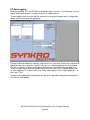
DC Controller / Flash Tab:
Any changed settings can be loaded or saved to the flash memory or to the PC from this page.
Saving settings to the flash memory (“Save to Flash”) provides a nonvolatile backup that can be
reloaded (“Load from Flash”) at any time as a default setting. Once stable settings are
determined, they should be saved to the flash memory and to the PC.
You can save your preferred settings to disk on the flash tab of SMI. This allows you to quickly
setup new or replacement controllers on production vehicles etc. Save your settings prior to
updating firmware. This is done by clicking on "save settings" under "command" drop down
menu on "user tab".
And always wait for communication to stabilize between steps.
DC750 User Manual ©2012 Synkromotive, LLC. All rights reserved.
Page 21
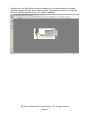
Firmware update:
If you receive a firmware update file from Synkromotive you may update the controller’s
firmware as follows:
While communicating with the controller but with key off, on “Flash” tab click “Firmware” “load
from disk”.
DC750 User Manual ©2012 Synkromotive, LLC. All rights reserved.
Page 22
Navigate to the .hex file provided by Synkromotive.
Confirm your selection if appropriate.
DC750 User Manual ©2012 Synkromotive, LLC. All rights reserved.
Page 23
Wait while progress bars indicate software update.
Wait for communication to normalize. The date of the code should be listed here.
DC750 User Manual ©2012 Synkromotive, LLC. All rights reserved.
Page 24
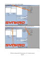
Automated Throttle Pot Calibration Process
With key off but the controller powered and fully installed, connect with the SMI interface and
go to the user tab and from the command drop down menu select calibrate pot.
Next, floor accelerator pedal and release; finish by selecting End calibrate pot from drop down
menu.
Now when you turn on the key on, flooring the accelerator pedal will target 100% of your
desired motor current regardless of throttle pot specification or mechanical limits. This also
works with most hall pedals.
If you installed a 2 wire pot then on the user tab select configuration setting using 2 wire.
DC750 User Manual ©2012 Synkromotive, LLC. All rights reserved.
Page 25
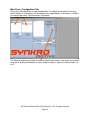
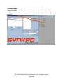
PC Data Logging
While connected to a PC, the DC750 can record data logs in real time. These data logs may be
requested by Synkromotive in response to technical support queries.
To start logging, make sure that the SMI software is running and navigate to the “Configuration”
tab on the left hand side of the application.
Choose the desired frequency under the “Log Interval (ms)” entry box. Choose the save location
and default log name under the “Log File” entry box. It is recommended that the “Date Stamp
File” box is checked, as doing so will append the date to the desired log file name before it is
saved, instead of overwriting any previous log file with the same name. To begin logging, click
on “Start Logging (F1)” or press the F1 key, and to stop logging, click on “Stop Logging (F1)” or
press the F1 key.
Connect to the laptop, Go to configuration tab and set the log folder to log to your desktop then
the Click on “start logging”.
DC750 User Manual ©2012 Synkromotive, LLC. All rights reserved.
Page 26
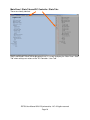
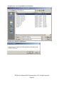
Data logs are in the XML format and may be read with any text editor however for simplicity
should be compressed into a .zip file and e-mailed to Synkromotive for viewing. The XML log
files can be also be opened in excel “as a read only workbook.”
DC750 User Manual ©2012 Synkromotive, LLC. All rights reserved.
Page 27
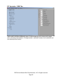
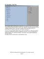
DC750 Specifications
Input Voltage Range (Nominal): 24 volts to 180 volts
Peak Battery Voltage (During Charging): 195 volts
Maximum Motor Current: 750 amps
Maximum Loss: 1.5 KW
Switching Frequency: 20 kHz
Operational Safe Temperature Range: -10°C to 40°C
Minimum Supply Voltage (Turn On): 11.7 volts
Off State Supply Current: 25 milliamps
DC750 User Manual ©2012 Synkromotive, LLC. All rights reserved.
Page 28
Warranty
Synkromotive One (1) Month Limited Warranty
WARRANTY COVERAGE
Synkromotive, LLC's warranty obligations are limited to the terms set forth below: Synkromotive,
LLC ("Synkromotive") warrants this hardware product against defects in materials and
workmanship for a period of ONE (1) MONTH from the date of original retail purchase. If a
defect exists, at its option Synkromotive will (1) repair the product at no charge, using new or
refurbished replacement parts, (2) exchange the product with a product that is new or which has
been manufactured from new or serviceable used parts and is at least functionally equivalent to
the original product, or (3) refund the purchase price of the product. A replacement product/part
assumes the remaining warranty of the original product or thirty (30) days from the date of
replacement or repair, whichever provides longer coverage for you. When a product or part is
exchanged, any replacement item becomes your property and the replaced item becomes
Synkromotive's property. When a refund is given, your product becomes Synkromotive's
property.
OBTAINING WARRANTY SERVICE
To determine if your product is eligible for warranty service, contact your Synkromotive dealer
with a description of the problem. When you contact the Synkromotive dealer, you may be
asked to furnish your name, address, telephone number, and proof of the original purchase
(receipt) containing a description of the product, purchase date, and the product serial number.
If the problem is eligible to be covered under warranty, they will then provide you with a Return
Goods Authorization ("RGA") number. Deliver the product, at your expense, to the address
provided by your Synkromotive dealer. Be sure to pack the item well and to reference the RGA
number both on the exterior of the box, as well as within the box. Be sure to also include contact
information and a concise description of the problem to expedite troubleshooting. Before you
deliver your product for warranty service it is your responsibility to keep a written record of the
any product parameters. You will be responsible for restoring all such parameters prior to use.
Data recovery is not included in the warranty service and Synkromotive is not responsible for
data that may be lost or damaged during transit or a repair.
EXCLUSIONS AND LIMITATIONS
This warranty does not apply: (a) to damage caused by accident, abuse, misuse,
misapplication, or non-Synkromotive products; (b) to damage caused by service performed by
anyone who is not authorized by Synkromotive; (c) to a product or a part that has been modified
without the written permission of Synkromotive; or (d) if any Synkromotive serial number has
been removed or defaced
THIS WARRANTY AND REMEDIES SET FORTH ABOVE ARE EXCLUSIVE AND IN LIEU OF
ALL OTHER WARRANTIES, REMEDIES AND CONDITIONS, WHETHER ORAL OR
WRITTEN, EXPRESS OR IMPLIED. Synkromotive SPECIFICALLY DISCLAIMS ANY AND ALL
IMPLIED WARRANTIES, INCLUDING, WITHOUT LIMITATION, WARRANTIES OF
MERCHANTABILITY AND FITNESS FOR A PARTICULAR PURPOSE. IF Synkromotive
CANNOT LAWFULLY DISCLAIM IMPLIED WARRANTIES UNDER THIS LIMITED
WARRANTY, ALL SUCH WARRANTIES, INCLUDING WARRANTIES OF MERCHANTABILITY
AND FITNESS FOR A PARTICULAR PURPOSE ARE LIMITED IN DURATION TO THE
DURATION OF THIS WARRANTY. No Synkromotive dealer, agent, or employee is authorized
to make any modification, extension, or addition to this warranty.
DC750 User Manual ©2012 Synkromotive, LLC. All rights reserved.
Page 29
Synkromotive IS NOT RESPONSIBLE FOR DIRECT, SPECIAL, INCIDENTAL OR
CONSEQUENTIAL DAMAGES RESULTING FROM ANY BREACH OF WARRANTY OR
CONDITION, OR UNDER ANY OTHER LEGAL THEORY, INCLUDING BUT NOT LIMITED TO
LOST PROFITS, DOWNTIME, GOODWILL, DAMAGE TO OR REPLACEMENT OF
EQUIPMENT AND PROPERTY. Some states and provinces do not allow the exclusion or
limitation of incidental or consequential damages or exclusions or limitations on the duration of
implied warranties or conditions, so the above limitations or exclusions may not apply to you.
This warranty gives you specific legal rights, and you may also have other rights that vary by
state or province.
DC750 User Manual ©2012 Synkromotive, LLC. All rights reserved.
Page 30
Contact Information:
[email protected]
Synkromotive, LLC
PO Box 2452
Portland, OR 97208
DC750 User Manual ©2012 Synkromotive, LLC. All rights reserved.
Page 31