1
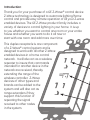
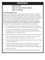
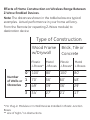
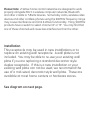
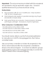
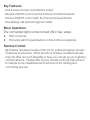
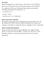
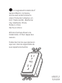
45605
Wireless Lighting Control
Duplex
Receptacle
Z-Wave® Certified
Wireless Lighting Control
Introduction:
Thank you for your purchase of a GE Z-Wave® control device.
Z-Wave technology is designed to automate lighting/home
control and provide easy remote operation of all your Z-wave
enabled devices. The GE Z-Wave product family includes a
variety of devices to control lighting in your home. It is up
to you whether you want to control one room or your entire
house and whether you want to do it all now or
start with one room and add more over time.
This duplex receptacle is one component
of a Z-Wave® control system and is
designed to work with all other Z-Wave
enabled devices in a home control
network. It will also act as a wireless
repeater to insure that commands
intended for another device in the
network are received, thereby
extending the range of the
wireless controller. Z-Wave
devices of other types and
brands can be added to the
system and will also act as
range extenders if they
support this function of
repeating the signal
received to other nodes
in the system.
CAUTION
This device is intended for installation in accordance
with the National Electric Code and local regulations
in the United States, or the Canadian Electrical Code
and local regulations in Canada. If you are unsure or
uncomfortable about performing this installation
consult a qualified electrician.
The device plugged into the Z-Wave controlled outlet on this
module must not exceed 600 watts (Incandescent);
15 Amps, 1800W (Resistive); or ½ HP (Motor). The maximum
rating for both outlets combined is 1800W (15A) Resistive.
There are no user serviceable parts in this unit.
NOT FOR USE WITH MEDICAL OR LIFE SUPPORT EQUIPMENT
Z-Wave enabled devices should never be used to supply power
to, or control the On/Off status of medical and/or life support
equipment.
Always-on Receptacle
Manual/Program Button
Z-Wave Receptacle
WARNING
RISK OF FIRE
RISK OF ELECTRICAL SHOCK
RISK OF BURNS
Controlling Appliances:
Exercise extreme caution when using Z-Wave devices to control
appliances. Operation of the Z-Wave device may be in a different
room than the controlled appliance, also an unintentional activation
may occur if the wrong button on the remote is pressed. Z-Wave
devices may automatically be powered on due to timed event
programming. Depending upon the appliance, these unattended
or unintentional operations could possibly result in a hazardous
condition. For these reasons, we recommend the following:
1. Assign Z-Wave controlled appliances to device numbers
10 – 18 on the GE remote. The likelihood of unintentionally
turning on the appliance will be reduced significantly
because the “Shift” button will need to be pressed before
pressing device numbers 10-18.
2. Z-Wave devices controlling appliances should be removed
from “All” control setting. Instructions on how to do this
are included in the manual for your GE remote.
3. Do Not include Z-Wave devices in Groups or Scenes if they
control appliances.
4. Do Not use Z-Wave devices to control electric heaters or
any other appliances which may present a hazardous
condition due to unattended or unintentional or automatic
power on control.
5. Double check programs for accuracy before using them.
Wireless Range
This device complies with the Z-Wave standard of open-air,
line of sight transmission distances of 65 feet. Actual
performance in a home depends on the number of walls
between the remote controller and the destination device,
the type of construction and the number of Z-Wave enabled
devices installed in the control network.
GE Z-Wave Network
Every Z-Wave enabled device acts as a signal repeater and
multiple devices result in more possible transmission routes
which helps eliminate “RF dead-spots”.
Things to consider regarding RF range:
- Each wall or obstacle (i.e.: refrigerator, big screen TV, etc.)
between the remote or a Z-Wave device and the destination
device will reduce the maximum range of 100 feet by
approximately 25-30%.
- Brick, tile or concrete walls block more of the RF signal than walls
made of wooden studs and plasterboard (drywall).
- Wall mounted Z-Wave devices installed in metal junction boxes
will suffer a significant loss of range (approximately 20%) since
the metal box blocks a large part of the RF signal.
Effects of Home Construction on Wireless Range Between
Z-Wave Enabled Devices.
Note: The distances shown in the table below are typical
examples. Actual performance in your home will vary.
From the Remote (or repeating Z-Wave module) to
destination device:
Type of Construction
Number
of Walls or
Obstacles
Wood Frame
w/Drywall
Brick, Tile or
Concrete
Plastic
Metal
J-Boxes* J-Boxes
Plastic
Metal
J-Boxes* J-Boxes
0** 100’
80’
100’
80’
1
70’
56’
60’
48’
2
49’
39’
36’
29’
3
34’
27’
21’
17’
* For Plug-in Modules or In-Wall Devices Installed in Plastic Junction
Boxes
** Line of Sight / no obstructions
Please Note: Z-Wave home control networks are designed to work
properly alongside 802.11 wireless computer networks, Bluetooth
and other 2.4GHz or 5.8GHz devices. Some baby cams, wireless video
devices and older cordless phones using the 900MHz frequency range
may cause interference and limit Z-Wave functionality. Many 900MHz
products have a switch to select channel “A” or “B”. You may find that
one of these channels will cause less interference than the other.
Installation
This receptacle may be used in new installations or to
replace an existing wall receptacle. A wall plate is not
included. You may be able to re-use your existing wall
plate if you are replacing a standard decorator style
duplex receptacle. If this is a new installation or your
existing wall plate can not be used, we recommend the
use of a mid-sized, decorator style wall plate. These are
available at most home centers or hardware stores.
See diagram on next page.
Green Ground
Wire connections
Green or Bare
Black (Hot)
Black
White
White
(Neutral)
WARNING
SHOCK HAZARD!
Turn OFF the power to the branch circuit at the circuit
breaker in your electrical service panel. Ensure power
is OFF before you install this device. All wiring connections
must be made with the POWER OFF to avoid personal
injury and/or damage to the switch.
1.
2.
3.
4.
5.
6.
7.
Shut off power to the circuit at fuse box or circuit breaker.
Remove wall plate.
Warning!: Verify power is OFF to receptacle before continuing.
Remove the receptacle mounting screws.
Remove the receptacle from the box.
Disconnect the wiring from the old receptacle.
Connect the Z-Wave receptacle as shown in the wiring
diagram.
8. Insert Z-Wave receptacle into outlet box being careful not to
pinch or crush wires.
9. Secure the receptacle to the box using the supplied screws.
10. Mount the wall plate.
11. Reapply power to the circuit at fuse box or circuit breaker and
test the system.
Observe Important Wiring Information
Always follow the recommended wire strip lengths and
wiring combination when making wiring connections.
You may wish to consult a electrician with questions or for
professional installation.
Important: The wire connectors included with this receptacle
are intended to only be used with copper wire. Consult a
qualified electrician if you have aluminum wiring.
Instructions:
1.
2.
3.
Strip insulation 3/8” for 12 or 14 AWG wire. Strip insulation
7/16” for 16 or 18 AWG wire.
Hold stripped ends together in parallel and align any frayed
strands (do not twist wires).
Push wires firmly into connector. Twist connector clockwise
with fingers until tight. Pull wires to check for tightness.
Wire Connector / Combination Chart
One #14 w/one-to-four #16 or #18 One #12 w/one-to-three #14 or #16 or #18
Two #14 w/one-to-three #16 or #18
Two #12 w/one or two #14 or #16 or #18
You should now be able to use the front panel pushbutton
to manually turn On/Off a lamp plugged into the Z-Wave
controlled outlet.
Use your primary controller to include the receptacle in the
home control network after the receptacle is installed as
shown in the above diagram. It can then be added to groups
and/or lighting scenes and managed remotely to control the
ON/OFF status of the connected lighting.
Key Features
- One Z-wave remote controlled AC outlet
- Remote ON/OFF control via the Z-Wave controller/network
- Manual ON/OFF control with the front panel pushbutton
- One Always-ON pass through AC outlet
Basic Operation
The connected light can be turned ON in two ways:
1.
2.
With a remote
Manually with the pushbutton on the Z-Wave receptacle
Remote Control
GE Z-Wave remotes provide control of an Individual device, Groups
of devices and Scenes. Other brands of Z-Wave Certified remotes
may not offer as much flexibility in how you can set up your lighting
control network. Please refer to your remote control’s instructions
for details on its capabilities and instructions for adding and
controlling devices.
Manual Control
The Pushbutton on the 45605 receptacle allows the user to:
1.
Manually turn the connected equipment ON or OFF by
pressing the button.
- This is a toggle switch; if the device is OFF, pressing the button
turns the device ON and vice versa.
2. Include or exclude the receptacle from the Z-Wave home control network with your primary controller.
- Refer to the instructions for your primary controller to access the
network setup function and include or exclude devices.
- When prompted by your primary controller, tap the button.
- The primary controller should indicate that the action
was successful. If the controller indicates the action was
unsuccessful, please repeat the procedure.
- Once the module is part of the network, the same basic
procedure is used to add the module to groups or scenes. Refer
to the primary controller’s instructions for details.
Please Note: After a power failure, the 45605’s Z-Wave controlled
receptacle returns to its last used ON/OFF state.
LED Indicator
- The LED will be lit when the Z-Wave controlled outlet is OFF.
- This is the factory default setting and can be changed if your
primary controller supports the node configuration function (see
Advanced Operation below).
ADVANCED OPERATION
The following Advanced Operation parameters require that you
have an advanced controller like the GE model 45601 Advanced
remote. Advanced remotes from other manufacturers may also
be able to change these settings; however, basic remotes do not
have this capability.
All-ON and All-OFF
Depending upon your primary controller, the 45605 receptacle can
be set to respond to ALL-ON and ALL-OFF commands in up to four
different ways. Some controllers may not be able to change the
response from its default setting. Please refer to your controller’s
instructions for information on whether or not it supports the
configuration function and if so, how to change this setting.
The four possible responses are:
- It will respond to ALL-ON and the ALL-OFF command (default).
- It will not respond to ALL-ON or ALL-OFF commands.
- It will respond to the ALL-OFF command but will not respond to
the ALL-ON command.
- It will respond to the ALL-ON command but will not respond to
the ALL-OFF command.
LED Light
When shipped from the factory, the LED on the 45605 is
set to turn ON when the connected outlet is turned OFF.
To make the LED turn ON when the light is turned ON,
change parameter 3’s value to “1”.
- Parameter No: 3
- Length: 1 Byte
- Valid Values = 0 or 1 (default 0)
Restoring Factory Defaults
All network settings and configuration parameters can all
be restored to their factory default settings by using your
master controller to reset the device. (delete it from network)
Over-Current Protection
Over-current protection is provided by an internal fuse
which is not user serviceable. Check your home’s circuit
breakers before concluding that the product must be
replaced.
Interoperability with Z-Wave™ Devices
A Z-Wave™ network can integrate devices of various classes,
and these devices can be made by different manufacturers.
Although every Z-Wave certified product is designed to work
with all other Z-Wave certified products, your controller must
include the appropriate device classifications in order to control
non-lighting Z-wave devices. As an example, the GE 45600 basic
remote is designed only for controlling Z-Wave devices using
the lighting control classification. The GE 45601 deluxe remote
with LCD readout can control other Z-Wave certified devices like
thermostats as well as lighting.
WARRANTY
JASCO Products warrants this product to be free from
manufacturing defects for a period of two years from the original
date of consumer purchase. This warranty is limited to the
repair or replacement of this product only and does not extend
to consequential or incidental damage to other products that
may be used with this product. This warranty is in lieu of all
other warranties, expressed or implied. Some states do not allow
limitations on how long an implied warranty lasts or permit the
exclusion or limitation of incidental or consequential damage, so
the above limitations may not apply to you. This warranty gives
you specific rights, and you may also have other rights which vary
from state to state. Please contact Customer Service at
800-654-8483 (option 4) between 7:30AM – 5:00PM CST or via our
website (www.easyzwave.com) if the unit should prove defective
within the warranty period,
JASCO Products Company
Building B
10 E Memorial Rd.
Oklahoma City, OK 73114
FCC
U2Z45605
The Federal Communication Commission Radio Frequency
Interference Statement includes the following paragraph:
The equipment has been tested and found to comply with the limits
for a Class B Digital Device, pursuant to part 15 of the FCC Rules.
These limits are designed to provide reasonable protection against
harmful interference in a residential installation. This equipment
uses, generates and can radiate radio frequency energy and, if not
installed and used in accordance with the instruction, may cause
harmful interference to radio communication. However, there is no
guarantee that interference will not occur in a particular installation. If
this equipment does cause harmful interference to radio or television
reception, which can be determined by turning the equipment off and
on, the user is encouraged to try to correct the interference by one or
more of the following measures:
- Reorient or relocate the receiving antenna
- Increase the separation between the equipment and receiver
- Connect the equipment into an outlet on a circuit different from
that to which the receiver is connected
- Consult the dealer or an experienced radio/TV technician
for help
Operation is subject to the following two conditions:
- This device may not cause interference
- This device must accept any interference, including interference
that may cause undesired operation
of the device.
Important Note: To comply with the FCC RF exposure compliance
requirements, no change to the antenna or the device is
permitted. Any change to the antenna or the device could result
in the device exceeding the RF exposure requirements and void
user’s authority to operate the device.
Compliance with IC Rules and Regulations
IC: 6924A-45605
Jasco Products Company
Model: 45605
ZW1001
This Class B digital device complies with Canadian ICES-003.
SPECIFICATIONS
Power 120VAC, 60Hz
Signal (Frequency) 908.42 MHz
Maximum load for both outlets; 1800W Resistive
Maximum Load for the Z-Wave controlled outlet: 600W
Incandescent, ½ HP Motor or 1800W (15A) Resistive
Range: Up to 100 feet line of sight between the Wireless Controller
and the closest Z-Wave receiver module.
Operating Temperature Range: 32-104° F (0-40° C)
For indoor use only.
Specifications subject to change without notice due to continuing
product improvement
Z-Wave is a registered US trademark of Zensys A/S
© 2009 JASCO Products Company
is a registered trademark of
General Electric Company
and is used under license to
Jasco Products Company LLC,
10 E Memorial Rd., Oklahoma
City, Oklahoma 73114
Made in China
Hecho en China
All brand names shown are
trademarks of their respective
owners.
Todas las marcas que aparecen
aquí son marcas registradas de
sus respectivos dueños.
45605-2
5/15/09