1
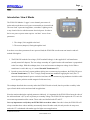
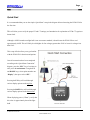
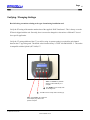
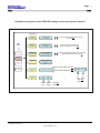
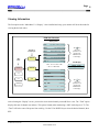
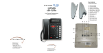
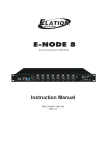
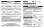
Page
1
Brultech Research Inc
ECM-1220 User’s Manual
Table of Contents
ECM-1220 User’s Manual...........................................................................................................................1
Table of Contents .......................................................................................................................................1
Introduction / How It Works ......................................................................................................................2
Safety..........................................................................................................................................................4
Quick Start .................................................................................................................................................5
Verifying / Changing Settings....................................................................................................................6
Installation..................................................................................................................................................8
Viewing Information................................................................................................................................12
Firmware Upgrade ...................................................................................................................................13
Specifications ...........................................................................................................................................15
© Brultech Research Inc
www.brultech.com
Page
2
Brultech Research Inc
Introduction / How It Works
The ECM-1220 Monitor / Logger is a two channel power meter. It
tracks and records the true (real) power consumed by an electrical load.
The term “load” represents an appliance, a machine, a lighting circuit,
or any electrical device which consumes electrical power. In order to
derive true power a power meter requires “real time” access of two
parameters:
1. The voltage (Volt) supplied to the load.
2. The current (Amperes) flowing through the load.
In order to access these parameters from a powered load, the ECM-1220 uses the most non-intrusive and safe
method of doing this:
1. The ECM-1220 reads the line voltage (120V household voltage) via the supplied AC wall transformer
(usually termed AC adaptor). The low voltage secondary AC signal from the wall transformer is proportional
to the line voltage. With this technique, there is no need to connect to dangerous voltage levels. When a
transformer is used in this way, it is termed Potential Transformer (PT).
2. In order to access the load’s current without splicing into a current carrying conductor, the ECM-1220 uses a
Current Transformer (CT). The CT simply clamps around one conductor supplying the load. (The CT
cannot be clamped around a power cord to the load since the two current carrying conductors inside the cable
are of opposite polarities and the magnetic fields cancel out.)
The technique described above not only makes the ECM-1220 safer to install, but also provides versatility in the
types of loads which can be monitored and its applications.
Since the monitor obtains the required parameters indirectly, it is important for the ECM-1220 to know the value of
the wall transformer’s (PT’s) ratio of primary to secondary voltage. The ECM-1220 also requires the CT’s ratio for
an accurate representation of the current. These values are labelled on the PT and CT.
It is very important to verify that your ECM-1220 is set to these values. Once this is done, the ECM-1220 will
always remember these values until they are manually altered. In other words, this only needs to be setup once,
unless the CT is substituted with another type for higher current applications.
© Brultech Research Inc
www.brultech.com
Page
3
Brultech Research Inc
Once the ECM-1220 is setup and monitoring a load, the energy consumption may be monitored and recorded in
several ways:
1. The non-volatile incrementing counter which display the kWh value, much like a residential power meter.
This counter keeps incrementing (with power usage) until the user decides to reset it.
2. The ECM-1220 also has internal memory for data logging. The “data logging” records and saves power
consumption data at a regular interval. This interval setting is selected by the user. Although the data is saved
at periodic intervals, this data represents and average of continuous sampling (several hundred samples per
second). This feature is available with the download option only.
3. The other method of monitoring is to have the ECM-1220 connected to a computer via USB cable or
wirelessly via optional Bluetooth. With this method, data can be collected at a resolution as low as once per
second. This feature is available with the download option only.
© Brultech Research Inc
www.brultech.com
Page
4
Brultech Research Inc
Safety
WARNING
•
Power the ECM-1220 with the supplied UL/CSA approved wall transformer only.
•
For indoor use only.
•
If installation is required in a damp location. Power the ECM-1220 via a GFI/GFCI protected outlet.
•
Installations requiring access to service panels, sub panels, junction box or any others situations where
live wires are exposed must be performed by a qualified person or electrician. This individual must be
familiar with the proper safety practices and equipped with the required PPE (Personal Protective
Equipment).
•
Any installations requiring access to service panels, sub panels, junction box or any others situations
where live wires are exposed are to comply with local safety codes and regulations.
•
Never connect the provided current clip to a bare or un-insulated conductor.
•
Prior to installation, always inspect the condition of the current transformer cable. Any damage to the
cables’ outside insulations must be repaired or the CT (current transformer) replaced.
•
When using the WPA-3 adaptor, always check the condition of the wire loop insulation before branching
into an electrical outlet. Check for cuts or damages to the insulation that would cause the centre
conductor to be exposed.... never pull on the loop to unplug the adaptor!
© Brultech Research Inc
www.brultech.com
Page
5
Brultech Research Inc
Quick Start
It is recommended that you use the simple “Quick Start” setup in the diagram below when using the ECM-1220 for
the first time.
This will allow you to verify the proper PT and CT settings (see Introduction for explanation of PT & CT) against a
known load.
Although a 100W incandescent light bulb is not an accurate standard, it should cause the ECM-1220 to read
approximately 100W. This will likely be a bit higher for line voltages greater than 120V or lower for voltages less
than 120V.
This setup will also allow you to get familiar
with the ECM-1220’s functions and options.
Once all connections have been completed
according to the “Quick Start Connection”
diagram, press the “ESC” key a few times to
take you to the main menu. Using the UP
and DOWN keys, select option number one
“Display”, then press select “SEL”.
Pressing the UP key will scroll through
various display options on the top line.
Pressing the DOWN key will scroll through
various display options on the bottom line.
When displaying power (“Watts”), verify that
this value is approximately that of the light
bulb.
© Brultech Research Inc
www.brultech.com
Page
6
Brultech Research Inc
Verifying / Changing Settings
Read all safety precautions relating to the type of monitoring installation used.
Verify the PT setting of the monitor matches that of the supplied “Wall Transformer”. This is factory set to the
PT that is shipped with the unit. Generally, there is no need to change this value unless a different PT is used
for a specific application.
Verify the CT setting with that of the CT you will be using. A separate setting is required for each channel
based on the CT type being used. The default value from the factory is TYPE: 100 and RANGE: 5 . This makes
it compatible with the Split-60 (SCT-60-B) CT.
“SEL” The “Select” key behaves
similarly to the ENTER key on a
computer.
The “DOWN” arrow is mostly used
for scrolling down.
The “UP” arrow is mostly used for scrolling up.
“ESC” The “Escape” key causes the
current display to go back to the
previous computer.
© Brultech Research Inc
www.brultech.com
Page
Brultech Research Inc
Flowchart showing the various ECM-1220 settings and the key sequence required
Setup
SetupOptions
Options
Main
Main
Menu
Menu
Display
Display
11.Modify
.ModifyCost
Cost
Of
Of Electricity?
Electricity?
Set
SetBilling
BillingRate
Rate
10.7
10.7cc//kWh
kWh
2.2.Modify
ModifyProj
Proj
Period
Period??
Set
SetProj.
Proj.Period
Period
30
30 Days
Days
3.3.Modify
ModifyLogger
Logger
Storage
StorageInterval?
Interval?
Store
StoreTo
ToLogger
Logger
Every
Every 15
15Mins
Mins
4.4.Reserved
Reserved
------------
Reserved
Reservedfor
forFuture
Future
Options
Options
Increment
Incrementor
orDecrement
DecrementRate
Rate(cost
(costof
ofelectricity)
electricity)
then
thenPress
PressSEL
SEL
Increment
Incrementor
orDecrement
Decrement##of
ofDays
Daysthe
the
Projection
Projectionis
isBased
Basedon,
on,then
thenPress
PressSEL
SEL
Increment
Incrementor
orDecrement
DecrementHow
HowOften
Often((minutes
minutes))the
theData
Data
Logger
LoggerWill
WillStore
StoreRecords,
Records,then
thenPress
PressSEL
SEL
Setup
Setup
Reset
Reset
Firmware
Firmware
(Future
(FutureOptions
Options))
Selects
SelectsCH1
CH1CT
CTOptions
Optionsthen
thenSEL
SEL
5.5.Select
Select“CT”
“CT”
Type
Type??
>>Ch1
Ch1
6.6.Select
Select“PT”
“PT”
Type
Type??
Type
Type
230
230
Ch2
Ch2
Selects
SelectsCH2
CH2CT
CTOptions
Optionsthen
thenSEL
SEL
Range
Range
55
Incr.
Incr.
Incr.
Incr.
CT
CT
CT
CT
Type
Range
Type
Range
Press
PressSEL
SEL
when
whendone
done
Range
Range
44
Incr.
Incr.PT
PT Incr.
Incr.PT
PT
Type
Range
Type
Range
Type:
Type:
100
100
Press
PressSEL
SEL
when
whendone
done
© Brultech Research Inc
www.brultech.com
7
Page
Brultech Research Inc
Installation
120V Wall Plugged Load:
If you wish to monitor a load which connects to a standard electrical outlet, use the diagram below to assist you in
the installation.
© Brultech Research Inc
www.brultech.com
8
Page
Brultech Research Inc
120V Panel circuit:
WARNING
•
Installations requiring access to service panels, sub panels, junction box or any others situations where
live wires are exposed must be performed by a qualified person or electrician. This individual must be
familiar with the proper safety practices and equipped with the required PPE (Personal Protective
Equipment).
•
Any installations requiring access to service panels, sub panels, junction box or any others situations
where live wires are exposed are to comply with local safety codes and regulations.
•
Prior to installation, always inspect the condition of the current transformer cable. Any damage to the
cables’ outside insulations must be repaired or the CT (current transformer) replaced.
The illustration below demonstrates a typical installation
for monitoring a 120V load at the panel. Example loads
would be:
• Any hardwired (permanently connected) appliance
such as a dishwasher.
• A load where the plug connection is too difficult to
access such as a refrigerator.
• Room lighting circuit
• Multiple loads connected to one circuit
© Brultech Research Inc
www.brultech.com
9
Page 10
Brultech Research Inc
240V Load From The Panel:
WARNING
•
Installations requiring access to service panels, sub panels, junction box or any others situations where
live wires are exposed must be performed by a qualified person or electrician. This individual must be
familiar with the proper safety practices and equipped with the required PPE (Personal Protective
Equipment).
•
Any installations requiring access to service panels, sub panels, junction box or any others situations
where live wires are exposed are to comply with local safety codes and regulations.
•
Prior to installation, always inspect the condition of the current transformer cable. Any damage to the
cables’ outside insulations must be repaired or the CT (current transformer) replaced.
The illustration below demonstrates a typical installation
for monitoring a 240V load at the panel.
One CT would be clamped on to the BLACK wire to the
breaker and the other to the RED (occasionally a second
black lead is used rather than red).
Do not clamp the CT around the WHITE neutral
conductor!
Example loads would be:
•
Central Air conditioning unit
•
Clothe Dryer
•
Electric Range
•
Hot Tub, Spa or Sauna
•
Electric Space /Baseboard Heater
•
Feed to a Remote Sub Panel such as power to a
garage, separate apartment, pool house, etc
© Brultech Research Inc
www.brultech.com
Page 11
Brultech Research Inc
Entire Service Panel or Sub-Panel:
WARNING
•
Installations requiring access to service panels, sub panels, junction box or any others situations where
live wires are exposed must be performed by a qualified person or electrician. This individual must be
familiar with the proper safety practices and equipped with the required PPE (Personal Protective
Equipment).
•
Any installations requiring access to service panels, sub panels, junction box or any others situations
where live wires are exposed are to comply with local safety codes and regulations.
•
Prior to installation, always inspect the condition of the current transformer cable. Any damage to the
cables’ outside insulations must be repaired or the CT (current transformer) replaced.
The installation required for monitoring entire
service panels or sub-panels is displayed in the
diagram on the right.
One CT would be clamped on to the BLACK wire
to the main breaker and the other to the RED
(occasionally a second black lead is used rather than
red). Read safety instructions above!
Do not clamp the CT around the WHITE neutral
conductor!
© Brultech Research Inc
www.brultech.com
Page 12
Brultech Research Inc
Viewing Information
The first option on the “Main Menu” is “Display”. Once installed and setup, your monitor will be in this mode for
viewing the desired values.
ECM-1220 Flowchart
Display Options
Channel To
Be Displayed
Main
Menu
Chan #1
CH x*
Days, Hours, Minutes, Seconds
CH x*
Line Voltage (Volts)
CH x*
Kilowatt-Hour Energy (kWh)
CH x*
Power (Watts)
Rate:
xx.x Cents per kWh (c/kWh)
Proj. =
The
Key
selects the
parameter to be
displayed on
Line #1 of the
LCD display.
xxx Days
LCD Display
Display
Firmware
(Future Options)
Display: Line # 1
or Tot total of CH1 + CH2
Display: Line # 2
Chan #2
Setup
Reset
CH x* : DISPLAYS CH1 or CH2
Power
(Watts)
Line Current
(Amps)
Peak (Max) Power
(Watts)
Total
(sum of CH1 +CH2)
Proj
$
Proj. kWh
xx,xxx.xxx
Cost:
CH x
xxx.xx
$
xxx.xx
The
Key
selects the
parameter to be
displayed on
Line #2 of he
LCD display.
Kilowatt-Hour Energy (kWh)
After selecting the “Display” screen, you need to select which channel you would like to view. The “Total” option
displays the sum of channel one and two. This option is handy when monitoring a 240V load using two CTs. The
“Total” will be the sum of the power from each leg. Use the UP or DOWN key to select the desired channel, then
SEL.
© Brultech Research Inc
www.brultech.com
Page 13
Brultech Research Inc
The “Display” screen shows various parameters. The top line of the LCD display is independent of the bottom line.
This provides the user with a multitude of display options. To change the top line, use the UP key. The DOWN key
will change the bottom LDC display line.
In the display mode, SEL has effect on only one parameter, “PEAK”. The “Peak” display is used to record the
highest Watt value monitored. To reset (erase) the “Peak” value, press the SEL button for approximately 6
seconds, while on the “Peak” display.
Resetting the Unit
Option “3. Reset” from the main menu is used to reset all cumulative values to zero.
This option has two prompt pages, to help prevent accidental erasure of data.
Firmware
Option “4. Firmware” displays the firmware version of your monitor.
What is firmware?
The firmware is the program that runs the Energy Monitor. This is equivalent to a computer program. The computer
program performs certain tasks and has specific features. On occasion, the software company may release a new
version of their software with more options or improvements. The same is true for the ECM-1220’s firmware. It is
called firmware because it stays resident in your Energy Monitor and the unit will always “boot-up” with this
program.
As Brultech Research releases newer versions of the firmware with improvement, the end user may upgrade the
firmware by re-programming the ECM-1220’s internal memory.
The firmware and required drivers and software are downloadable from www.brultech.com/ecm1220/firmware.
The optional USB data cable may be ordered from the company you purchased your monitor from.
© Brultech Research Inc
www.brultech.com
Page 14
Brultech Research Inc
Data Logger
The data logger section is only viewed by downloading the collected data using the optional software.
How the Logger Collects/Records Data:
The data logger section of your monitor continuously tracks the amount of energy used, then at the user selected
storage interval, stores the average energy for that period.
For example:
Suppose the monitor’s storage interval is set to store data every 10 minutes and during 5 minutes of that interval a
500 watt loads is operated, then OFF for 5 minutes, the stored data would be 250 watt. This is the average power
used during that interval. Once downloaded the software will calculate and display the accumulated kilowatt-hour
during that interval. For the same scenario as above, if the storage interval was set to 1 minute storage interval, after
10 minutes, 10 data records would have been stored; 5 records of 500 watt and 5 records of 0 watt.
From this example, it is obvious that a lower storage interval is preferred. The trade-off is the amount of time you
can monitor before the data logger memory becomes full.
The data logger collects and stores data at its user programmed storage interval until the memory is full. Once the
memory is full, it WILL NOT overwrite the data. At that point the data is no longer recorded. This has NO
EFFECT on the Energy Consumption Monitor’s operation, as it will continue to operate normally.
When the Energy Monitor is RESET, the data logger memory is cleared then starts logging at the beginning. This
also resets the Energy Monitor’s cumulative data such as KWh, Cost and Elapsed Time.
Downloading Data Logger Records:
The download software is optional and comes with various drivers and USB data cable.
Before data can be downloaded for the first time, two “drivers” will need to be installed on the computer. The
software CD has the drivers and installation instructions.
Once the drivers are installed the Energy Monitor is then connected to the USB port of your computer with the
supplied data cable. (When connected for the first time, Windows will discover the new hardware). The download
procedure is straightforward, using the software.
© Brultech Research Inc
www.brultech.com
Page 15
Brultech Research Inc
Real Time Data
The optional software comes with the ability of viewing energy usage in “real time” (as it happens). When enabled
with the software, data is transferred to the connected computer every second. The data transferred is:
CH1 Power (watt)
CH2 Power (Watt)
Line Voltage (volt)
This information is displayed in a scrolling box. The data displayed can be transferred from the box to another
program by highlighting the records, saving it to the clipboard, then pasting it into your application. When pasting
to a spreadsheet, the “tab delimited” option should be used.
Specifications
Display:
2 Lines X 16 Characters Alpha Numeric
Blue background with white backlight
Size:
5 ½” X 4” X 1 ½”
Power:
Digitally sampled true power.
1 Watt to 65,000 Watt ( 1 Watt resolution)
Power/KWH Accuracy:
± 1% plus CT accuracy
Typically ± 2% with most current sensors
Energy:
.001 kWh to 16,777.216 kWh (.001 kWh resolution)
Voltage:
85V to 480V depending on the Potential Transformer used.
Standard Package Comes With PT:
Line Voltage: 85V to 130V
Secondary: 12VAC 300mA 3.5mm mono phone plug
Use ONLY supplied “Wall Transformer”
CT Inputs (balanced):
333mV RMS Full Scale, 353mV RMS Max
Input Impedance: 20Kohm
Stereo 3.5mm Plug: Ring(-V), Tip(+V) Sleeve(N.C.)
© Brultech Research Inc
www.brultech.com
Page 16
Brultech Research Inc
CT Inputs (unbalanced):
3.0 V RMS Max
Input Impedance: 107 Ohm
Mono 3.5mm Plug: Tip(+) Sleeve(-)
Input Current:
Dependant on Current Transformer
Wall Plug Adaptor (WPA-3) Rating:
120 VAC
15 Amps
Elapsed Monitoring Time:
MAX: 255 days, 23 hrs, 59 min, 59 seconds (1 second resolution)
Rate (cost for electricity):
0.1 /kWh to 99.9 ¢/kWh (in 0.1 ¢/kWh resolution)
Displayed Cost of Energy:
0.1¢ to $ 12000.00
Projection Period:
1 day to 255 days (typically set to 7days, 30 days, 60days or 90 days)
Data Logger Storage Interval:
From 1 minute to 255 minutes (1 minute increments)
(Stored data is the average of thousands of samples over that period)
Data Logger memory:
EEPROM Technology (non-volatile)
Standard Unit 13,080 records
Optionally expandable to 52,401 records (in 13,107 increments)
Firmware:
Flash, user reprogrammable
© Brultech Research Inc
www.brultech.com