1
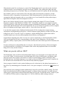
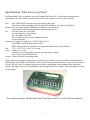
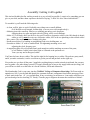
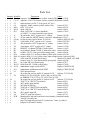
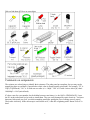
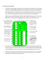
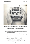
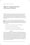
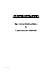
The 1802
Membership Card
For me and you and the 1802
by Lee Hart
814 8th Ave N
Sartell MN 56377
[email protected]
last revised: 5/16/2012
What the heck is this? It's an adventure, by cracky! The "Membership Card" is your ticket to the weird and
wonderful world of microcomputing. Our guide will be the COSMAC 1802, perhaps the oddest and most
entertaining microprocessor yet invented. I hope you will find this manual to be equally odd and entertaining.
The COSMAC 1802 was created in the 1970's at the dawn of the microcomputer revolution, by Joseph
Weisbecker of RCA Corporation. It used their new CMOS fabrication process, which had very low power
consumption, high noise immunity, and was very simple to use. It was intended for military and aerospace;
applications too tough for other microcomputers to survive.
But Joe was a hacker at heart. He wrote a series of articles starting in the August 1976 issue of Popular
Electronics magazine called "Build the COSMAC ELF". It described a simple low-cost computer, using the
1802 microprocessor. At the time, microcomputer systems cost hundreds to thousands of dollars. (Hmm... they
still do today!) But Weisbecker's ELF cost less than $100! Yet, it was an honest-to-goodness real live computer,
able to do anything its much bigger cousins could do -- albeit a bit slower and cruder.
It was the ideal computer trainer. Hobbyists built thousands of ELFs, learning about computer design,
construction, and programming in the process. A dozen companies began producing versions of the ELF, also
selling for low prices. It was the "Legos" of computers; a simple building-block computer that could be
assembled many ways to become almost anything, limited only by your imagination.
I learned about computing on my ELF. It set me on a career in engineering, as it did for thousands of others.
1802's got designed into all sorts of amazing things; video games, music synthesizers, Chrysler engine
computers, military weapon systems, and even NASA missions such as the Galileo spacecraft. Eat stardust, x86
PCs!
So return with me now to those thrilling days of yesteryear, when the heroic pioneers of the microcomputer
revolution learned how to build their own computers from scratch, and programmed them to do incredible
things, all for a tiny amount of money!
What can you do with an 1802?
The Membership Card is much like the Parallax BASIC Stamps; you can program it to do simple tasks, and
serve as the "brains" of various projects. It can blink lights, drive relays or small motors, run displays, make
annoying sounds with a speaker, read switches or sensors to measure things, perform calculations, make
decisions, and more. Its machine language is very simple, or there are BASIC interpreters and C compilers for
the 1802 that can be downloaded free to write and run really ambitious programs.
Once a program is loaded, it can be retained without power for a short time by the onboard supercapacitor, or
kept forever by maintaining power. Remember, this is a low power computer; it will run for a year on three AA
cells!
The Front Panel can be unplugged, and the Membership Card used by itself (like a BASIC Stamp). The Front
Panel isn't needed until you want to change the program, or debug or observe operation. For stand-alone use,
connect power, ground, and your desired input and output devices to the 30-pin header directly. Jumper J1 pins
13-14 (RUN to VDD) to turn it on. Jumper pins 10-11 (/WE to /MWR) to enable writing to memory.
2
Specifications: What have we got here?
The Membership Card is a miniature copy of the original PopTronics ELF, built using modern parts and
repackaged to fit in an Altoids tin. It's got the basics of every computer; a CPU, memory, and I/O.
CPU:
RCA CDP1802ACE microprocessor (the brains of the outfit)
clock: RC oscillator, adjustable from 20-1000 KHz (KiloHertz; not Mega- or GigaHertz)
Memory: 2k to 32k bytes, RAM or EPROM (that's kilobytes, not megabytes)
supercapacitor holds data and programs in RAM without power
I/O:
one 8-bit output port, with LEDs
one 8-bit input port, with switches
one 1-bit output, with LED
four 1-bit flag inputs, one with a pushbutton switch
one interrupt input
Connectors: 4-pin power connector (+V, RUN, LED, and -V)
25-pin DB25 connector with all the I/O on it
DB25 can plug into a PC parallel port to operate the Membership Card with the PC
Size:
3-1/2" x 2-1/8" x 3/4" (89 x 54 x 19 mm)
Power: voltage: 3v to 5v DC
current: 0.1 to 1ma (depending on clock speed and supply voltage)
plus 1-3ma for each LED that is on
Aroma: a hint of curiously strong peppermint
Unlike modern microcomputers that require an expensive PC and huge software programs to do anything, the
Membership Card is totally self-sufficient. No PC is needed, and no special software is required. You can power
it from a few AA cells or a scrapped calculator solar panel, and program it with nothing but the front panel
switches and lights. If you ever get stranded on a desert island and need to compute, this is the computer to have
in your pocket.
The complete package: Membership Card, Front Panel, and Cover Card, all in an Altoids tin.
3
Assembly: Getting it all together
This ain't no Heathkit, but I'm working to make it as easy to build as possible. I want it to be something you can
give to your kids, and have them experience the thrill of saying, "I did it! It's alive! Bwoo hah hah hah..."
To assemble it, you'll need the following tools:
- A clean, well-lit, place to work. Preferably one without cats or small children.
Or if the kids are old enough, let them help. (Cats are never old enough to help.)
- Soldering iron with a small tip. Don't use a soldering gun unless you're desperate;
soldering these tiny parts and pads with a big fat tip will be a real challenge.
- Solder. 63/37 tin/lead is best, but 60/40 is also good. Lead-free electronics solder is also OK, though it doesn't
solder as well. It must be rosin core electronics solder; NOT acid core plumbing or sheet metal solder!
- Wire cutters. The smaller the better. Nothing is big here.
- Needle-nosed pliers. For bending or straightening lead wires, holding nuts, etc.
- Screwdriver with a 1/8" wide or smaller blade. For tightening mounting screws and
adjusting the clock frequency pot.
- A magnifying glass. My old eyeballs aren't good enough to read the markings on some of the parts,
or see whether a solder joint is done right or is shorted to the pad next to it.
Your eyes may not be that good, either.
You'll need to know how to solder. This isn't the right kit for learning how to solder. The pads are pretty small,
and if you make a mistake, it can be a real bear to get the part off and put back on the right way.
First, make sure you have all the parts. I supplied everything that goes on the printed circuit board, but you may
need to gather a few other things yourself. I'll supply Altoids tins as long as my supply holds out (not long), but
you will have to drill or cut the holes in it for the switches, LEDs and connectors.
The Membership Card is your entry into the COSMAC College of Computer Knowledge. We'll start with an
aptitude test. See if you can find and identify the common electronic components listed on the next page. Place
a check mark in the box ( X ) as you find them. If any are missing, let me know so I can send it out before you
get bored and go back to watching TV. Ready? Turn the page to begin an adventure that could last a lifetime...
Membership Card
Front Panel Card
4
Parts List
(
(
(
(
(
(
(
Quantity
) 1
) 4
) 1
) 1
) 9
) 2
) 1
(
(
(
(
(
(
(
(
(
(
(
(
(
(
(
(
(
(
(
(
)
)
)
)
)
)
)
)
)
)
)
)
)
)
)
)
)
)
)
)
1
1
3
1
1
1
1
1
1
2
4
1
1
1
2
11
1
1
40
1
(
(
(
(
(
(
(
(
(
(
(
(
)
)
)
)
)
)
)
)
)
)
)
)
28
1
1
1
1
1
1
1
1
1
1
4
Identifier
Description
Source
C1
capacitor, 22pF NPO ceramic (yellow, marked 22K)Jameco 332541
C2-4,7 capacitor, 0.1uF X7R ceramic (yellow, marked 104) Jameco 544868
C5
supercapacitor, 0.047F, 5.5vdc (green, 0.5" dia.)
C6
capacitor, 100pF ceramic (yellow, marked 101)
Jameco 81525
D0-8
LED, T1-3/4, red
Jameco 697611
D9,10 diode, 1N4148
Jameco 36038
D11
diode, 1N5231B 5.1v zener (standard)
Jameco 179047
or 1N4625 5.1v zener (optional; lower power)
J1
30-pin header, 0.025" sq.pins on 0.1" centers
Jameco 103342
J2
25-pin connector, DB25F female, vertical PC mountJameco 15165
P1a,b,c 10-pin top entry socket, Molex 22-18-2101
Digikey WM3241-ND
P2
5-pin header, 0.025" sq.pins on 0.1" centers
Jameco 2076789
P3
4x2 pin header, 0.025" sq.pins on 0.1" centers
Jameco 109516
P4
4 pin header, 0.025" sq.pins on 0.1" centers
Jameco 117560
Q1
MOSFET, N-channel 2N7000 (3 leads, black)
Jameco 119423
R1
1meg trimpot, Bourns 3266W (3 leads, blue cube) Jameco 696386
R2
resistor, 5.6k 5% 1/4w (green-blue-orange-gold)
Jameco 691041
R3,6
resistor, 100k 5% 1/4w (brown-black-yellow-gold) Jameco 691340
R4,8-10 resistor, 499k 1% 1/4w (yellow-white-white-orange-brown) Jameco 691500
R5
100k 9-pin SIP, 8x100k (black body)
Mouser 652-4609X-1LF-100K
R7
resistor, 1meg 5% 1/4w (brown-black-green-gold) Jameco 691585
R11
1k 10-pin SIP, 9x1k (black body)
Jameco 97877
R12,13 100k 8-pin SIP, 7x100k (yellow body)
Jameco 276358
S0-10 subminiature toggle switch, SPDT
Digikey CKN1059-ND
S11
subminiature pushbutton switch, SPDT
Digikey CKN1740-ND
U1
1802 microprocessor
40 socket pins (or low-profile IC socket) for U1
(Mouser 575-393640)
U2
RAM; 6116 (2k), 6264 (8k), 62256 (32k), or 43256 (32k)
(or EPROM; 2716-27256 or 27C16-27C256; 2k-32k)
28 socket pins (or low-profile IC socket) for U2
(Mouser 575-393628)
U3
74HC373 or 74HCT373 octal latch
Jameco 45831
U4
4093 quad 2-input NAND
Jameco 13400
U5
4013 dual D flip-flop
Jameco 893443
U6
74HC244 or 74AHCT244 octal buffer
Jameco 45655
U7
74HC374 or 74HCT374 octal D flip-flop
Jameco 45858
U8
4071 quad 2-input OR
Jameco 13274
U9
74HC257 quad data selector
Jameco 45719
PCB
Membership Card and Front Panel circuit boards (2 attached boards)
"Altoids" tin candy box
bag of #4 hardware to mount J2 (2 jackscrews, 2 nuts, 6 washers)
jumpers for P2 and P3 headers
5
Did you find them all? Here are some hints:
Comments on components
The resistors use colored rings to identify their resistance. The other parts have numbers, but you may need a
magnifying glass to read them. Capacitors have their value in Farads (usually picoFarad). For example, "22" is
22pF (22 picoFarad). "101" is 10 with one zero after it, i.e. 100pF. "104" is 10 with 4 zeroes after it pF; that's
100,000pF = 0.1uF (microFarad).
ICs have room for a part number, but it's hidden between extra letters (i.e. the 1802 is CDP1802ACE). Leave
the ICs in their tubes until you're ready to install them. They are easily damaged by static electricity. You know
that teeny little spark you get if you touch something metal after petting the cat or walking across a carpet?
That's static electricity. In the microscopic world inside an IC, it hits like a lightning strike. Boom! Your IC is
dead.
6
Assembly
Assembly is a work in process. I'll just describe how I built mine. Please let me know if you find better ways to
do it! Check off the steps as you go ( X ), in case you get interrupted and have to come back to it later.
A couple things to keep in mind: To fit both boards in an Altoids tin, they must be built with the parts as low as
possible. Standard IC sockets are too high, so I've supplied special low-profile socket pins. Likewise, the
plastic bodies of the 0.025" square pin headers (J1, P2-4) are too tall, so they have to be removed after
soldering. You'll also need to trim the leads on the back sides of the boards very short as you go.
Ready? Let's get started!
Membership Card assembly
All parts go on the side of the board with the white silkscreened lettering (the top or "component side"). All
soldering is done on the other side (the back or "solder" side). The only exception is for P1a, b, and c (I'll
remind you when we get to it).
( )
Find C1; a 22 pF ceramic capacitor (yellow body, labelled "22" or "22K"). Straighten the leads if
necessary with your needle-nosed pliers. Insert the leads into the holes on the board in the box at the
location marked "C1". Bend the leads outward slightly to hold it on the board. Turn the board over, and
solder each lead. Cut off the excess lead length.
Now repeat this proceedure for the rest of the capacitors.
( )
( )
( )
C2: 0.1uF (yellow, marked "104").
C3: 0.1uF (yellow, marked "104").
C4: 0.1uF (yellow, marked "104").
( )
C6: 100pF (yellow, marked "101"). Note: This one is smaller and different from C2-C4. Don't get them
mixed up!
( )
C5: 0.047F (green, marked "0.047F"). Two black stripes mark the negative side. The pin next to the
black stripes must go in the hole in the board by the "-" sign. Bend the leads slightly to hold it in place,
then solder the leads, and cut off the excess.
7
Now for the resistors:
( )
Find R1; it's a 1 megohm trimpot (a little blue cube with 3 leads, marked "W105"). Put it at location
"R1", bend the leads to hold it, solder them, and cut off the excess.
( )
Find R2; a 5.6k ohm 5% resistor (color bands are green-blue-orange-gold). Bend the leads close to the
body. Insert the leads into the holes on the board at the location marked "R2". Bend the leads outward
slightly to hold it, solder each lead, and cut off the excess.
Repeat this proceedure for the rest of the resistors.
(
(
(
(
)
)
)
)
( )
R3: 100k 5% (brown-black-yellow-gold).
R4: 499k 1% (yellow-white-white-orange-brown).
R6: 100k 5% (brown-black-yellow-gold).
R7: 1 meg 5% (brown-black-green-gold).
R5: This is a 9-pin SIP (Single Inline Plastic) package with eight 100k resistors in it (black body,
marked "L91S104"). Note the end with the white line; this is "pin 1". Place it on the board at location R5
with the pin 1 end next to C4. Bend two of the leads slightly to hold it in place, then solder each lead,
and cut off the excess.
Diodes: They are polarity sensitive, and have a black band at one end. Be sure the banded end matches the band
shown on the board!
( )
( )
( )
D9: 1N4148 (a reddish glass tube, with a wire at each end, and "1N4148" printed on it in tiny letters).
Bend the leads, and place it on the board at "D9" with the banded end as shown on the board. Solder
each lead, and cut off the excess.
D10: 1N4148. Install it the same as D9.
D11: 1N5231B. Install the same as D9 and D10.
IC socket pins (or sockets): You have some choices here. Ideally, you don't need sockets or socket pins; they
add cost, make the board higher, and a little less reliable (sockets will be the least reliable part of the whole
computer). But having them makes troubleshooting and chip replacements easier.
( )
U1: 1802 integrated circuit. I supplied socket pins, which require some fussy work. They have an
extremely low profile, but are tiny and easy to lose! Push a socket pin onto each pin of the 1802 IC. Put
the 1802 with socket pins on the board, and then solder all the pins. Do not use too much solder, or it
will solder the IC to the board! If you do it right, the 1802 can be unplugged from the board just like an
IC in a socket. Do not cut the socket pins! The bottom needs to remain closed so solder won't get inside.
If you want to use your own IC socket, place it at location "U1" with the end with the notch matching
the one shown on the board. Solder each pin, and cut off the excess. Install the 1802 in the socket (with
pin 1 at the correct end).
( )
U2: memory chip (could be a RAM or EPROM, from 2k to 32k bytes). Install as described for U1
above.
8
Now let's do the rest of the ICs. I did not supply sockets or socket pins for them. They are not likely to fail, and
the sockets cost more than the chips. You can add sockets if you like, but it is likely to increase the height.
ICs are polarity sensitive; they must be installed with the pin 1 end matching the marking on the board. The pin
1 end may be marked in a number of ways; with a dot, notch, or line, etc. When the writing on the IC is right
side up and facing you, pin 1 is at the lower left corner. See the illustration on page 6 to find pin 1.
For each IC, make sure its pins are straight and parallel to each other so it fits into the holes on the board. If they
are bent slightly, straighten them with your needle nosed pliers.
( )
(
(
(
(
)
)
)
)
U3: 74HC373 (or 74HCT373) 20-pin IC. Install at U3, and bend a couple pins slightly if necessary to
hold it in place. Be sure pin 1 is at the correct end! Then solder all pins, and cut off the excess.
U4: 4093 14-pin IC. Install the same as for U3.
U5: 4013 14-pin IC.
U6: 74HC244 (or 74AHCT244) 20-pin IC.
U7: 74HC374 (or 74HCT374) 20-pin IC.
We're almost done. Now for the pin headers.
( )
J1: 30-pin header. The little square pins are held by a black plastic body. If you don't plan to put the
boards in an Altoids tin, just put the header on the board, and solder it in place.
If you DO want it to fit in an Altoids tin, the plastic body must be removed. Here's how I did it:
- Put the pin header loosely in a small vice, with the plastic body sitting on top of the jaws.
- Pound the short end of each pin into the plastic, so all of the pin sticks out the other side.
- Insert the pin header from the BACK side of the board, with the plastic body about 1/8"
away from the bottom of the board (so the pins stick up about 1/4" above the top of the board).
- Solder each pin from the TOP side of the board.
- Cut each pin on the BACK side of the board. This also removes the black plastic body.
( )
P2: 5-pin header. Mount P2 the same as above. The pins must not stick up more than 1/4" above the
board.
( )
P3: 6-pin header. I supplied an 8-pin part. Remove two of the pins so it will fit on the board. Then mount
the same as J1 and P2. The pins must not stick up more than 1/4" or they will short to the Front Panel
board.
( )
Q1: MOSFET transistor (2N7000). This is also a static sensitive part, so beware of static electricity.
Position the flat side of the body to match the outline on the board. Put each lead in its respective hole.
Solder Q1 and cut off the excess lead length.
9
Front Panel assembly
( )
Use the bare front panel board as a template to drill your front panel (an Altoids tin, or your own plastic
or metal one). I use the bottom of the Altoids tin as my "front panel". Drill small 1/32" guide holes for
the switches, LEDs, D-connector mounting holes, and 4-pin power connector P4. Then remove the PC
board, and drill the holes to their final sizes. Use a "step" drill bit, which won't tear the very thin metal
(this is a long drill bit with a single cutting edge with steps in it to drill a dozen or so sizes from 1/8" to
1/2"). The D-connector opening will have to be cut out with a nibbler or a lot of hand filing.
Flash! I now have a Cover Card with all the holes and silkscreened labels (see page 17). Just cut a big
ragged hole in the bottom of the Altoid tin; lay this card over the hole; and solder, glue, or screw it in
place. The Cover Card is $10 plus $2 shipping from me (Lee Hart); contact info is on the cover.
( )
Now, fit the PC board with the LEDs and switches into the holes in your front panel. Work the board
down as close as possible to the metal panel. This forces all the parts into the correct positions to match
your front panel holes. Careful! The switches can break if your front panel holes don't match the board
well enough. NOW solder the parts to the board, with the front panel holding them all in position.
( )
Remove the screws from the D-connector. Remove the PC board from the panel, so you can install the
rest of the parts. The above may seem tedious, but it guarantees that the parts will be soldered in the
right positions to match the holes in your front panel.
10
( )
P1a, P1b, P1c: Mount these connectors on the BOTTOM of the Front Panel board. Three 10-pin parts
are supplied, as I couldn't find a single 30-pin part. The two "feet" point to the center of the board. Cut
off these feet after the connectors are mounted.
( )
R11: 10-pin SIP resistor network with nine 1K resistors (black, marked "E1K"). Note the end with the
black dot or line; this is "pin 1". It goes on the LEFT end, toward the center of the board and in the hole
with the square solder pad. Solder each lead and cut off the excess.
Install R12 and R13 exactly the same as R11:
( )
( )
R12: 8-pin SIP with seven 100K resistors (yellow, marked "8X-1-104LF").
R13: 8-pin SIP with seven 100K resistors (yellow, marked "8X-1-104LF").
Install the fixed resistors and capacitor as was done on the Membership Card:
(
(
(
(
)
)
)
)
R8: 499k 1% (yellow-white-white-orange-brown).
R9: 499k 1% (yellow-white-white-orange-brown).
R10: 499k 1% (yellow-white-white-orange-brown).
C7: 0.1uF (yellow, marked "104").
Install the ICs the same as U3-U7 on the Membership Card. Be sure pin 1 is as shown on the board:
( )
( )
( )
U8: 4071 14-pin IC.
U9: 74HC257 16-pin IC.
P4: 4-pin header. Install as described for J1 on the Membership Card. Or if you prefer, leave off P4 and
solder 4 small wires to the board instead, with a connector on the other end.
( )
Check to see that the finished board still fits into the holes in your front panel. You may have to re-heat
and reposition some parts, or enlarge some holes in your front panel to make it fit easily.
( )
The last page of this manual is a "cheat sheet" summary of operation. Cut out one vertical column, and
fold it to fit inside the Altoids box. This keeps it handy for a quick reminder. It also keeps the pins on the
back of the board from shorting to the metal case!
Final Assembly
( )
Plug the Membership and Front Panel boards together. Look between them for any places where parts
touch each other and could cause a short. Trim any leads that are too long and might touch.
( )
I don't have enough nuts for all the switches, and haven't found a place to buy them; so I only supplied 4
sets. That's OK; they are so close that you can't put nuts on adjacent switches anyway. Just use nuts on
the end switches in each row. Don't bother with washers; there is no room for them.
11
Next, you need to install jumpers on the Membership Card to configure it for the particular size and type of
memory chip installed at U2:
( )
P2 and P3: Look at the type of memory chip installed at U2. Ignore the letters at the beginning and end
of the part number, and focus on the 4-digit or 5-digit number in the center. For example, suppose it is
marked "D43256AC-10L" -- then it's a 43256 (a 32k byte RAM).
( )
Find the table at the bottom left corner of the schematic. Look up your chip number to see what jumpers
to install. For a 43256 for example, install jumpers at P2 between pins 1-2 and 4-5, and at P3 between
pins 1-3 and 2-4.
Power On
Now it's time for the smoke test! We'll connect power, and try not to let any of the magic smoke out. (Old
timers will tell you that electronic devices don't work after smoke comes out.)
The Membership Card takes very little power; 3v to 5v DC at less than 1 milliamp, plus a milliamp or so for
each LED that's lit. You can use a few 1.5v batteries, an old cellphone charger, or even a solar panel from a
scrapped calculator for power. For example, a battery holder with three AA cells in another Altoids tin. Or,
most cellphone chargers have a 5v DC output; read the label carefully, and if yours is, it can be used.
Zener diode D11 on the Membership Card is an "idiot" diode. If you connect the power supply backwards, or if
it's over 5.1 volts, or is AC instead of DC, then D11 will try to short it out and protect the rest of the parts on the
board. At worst, D11 will get hot and fail shorted; but it's cheap and easy to replace.
P4 is the power connector. It's a common male header with four 0.025" square pins on 0.100" centers, located in
the top left corner of the Front Panel board. There are many mating connectors. For example, the 4-pin cable
used in PCs between the CDROM drive and sound card can be used. Other choices include:
- Molex KK series: 22-01-3047 housing, 08-55-0102 terminals (www.jameco.com 234819, 234931).
Common and easy to use, but not latched or keyed.
- AMP-latch series: 25403S-04 header, 25403H-04-R housing, 25403T terminals (www.jameco.com 152734,
152741, 181673). Higher quality, latched and keyed (if you use its header); but hard to install terminals.
Pin
1
2
3
4
Name
+
RUN
LED
-
Function
VDD, the power supply positive; +3 to +5 volts DC.
Controls the 1802's clock oscillator. Connect to pin 1 to Run; leave pin 2 open to Stop.
LED negative. Connect to pin 4 to enable the LEDs; leave pin 3 open to disable the LEDs.
VSS, the power supply negative (ground, common).
Pin functions are shown above. Your power connector should connect your power supply's positive to pins 1
and 2, and the negative to pins 3 and 4. To turn the Membership Card "on", plug this connector onto the board
to make RUN high (clock runs) and LED low (LEDs enabled). Unplug the connector to turn it "off"; RUN goes
low to stop the clock, and the LEDs are disconnected, minimizing power. When unplugged, supercapacitor C4
will hold the program and data in RAM for many minutes.
12
If you want to maintain the program and data in RAM indefinitely, leave power connected to P4 pins 1 and 4.
Use a DPST (double pole, single throw) switch to break the connections between pins 1-2 and 3-4. This switch
provides "on" and "sleep" operation. "On" enables the clock and LEDs to work normally. "Sleep" holds
memory contents but keeps the power very low; a set of AA cells will maintain memory for a year.
Once you have power connected (and nothing smokes), proceed to the "Operation" section following to see if
it's working!
Operation
The Front Panel selects the 1802's operating mode and shows its status. The eight Data switches S7-S0 set the
data to be input. S12 is the IN pushbutton; pressing it loads the data. Data LEDs D7-D0 display the last data
loaded or output by the 1802 program. LED D8 shows the status of the 1802's "Q" register.
S8 is the READ/WRITE switch; it controls whether you can read or write to memory. S9 and S10 are the mode
switches, CLEAR and LOAD. They select the four operating modes as follows:
Mode
LOAD
CLEAR
WAIT
RUN
S9
CLEAR
down
down
up
up
S10
LOAD
down
up
down
up
1802 Operation
Waits for the next memory read/write (next press of the IN button).
Reset the 1802 (sets registers Q, X, P, and R0 all to 0).
Stops the program running in memory, and waits right where it is.
Runs (or resumes running) the program in memory.
Here's an example of how these switches and lights work.
1. Power up the card. Set switches S11-S0 as shown. "1" means the switch is up. "0" means the switch is
down. "X" means push the button. "." means the switch state doesn't matter. I'll show the switch positions
like this:
Switch numbers and positions on the board
S11 S10 S9 S8
. 1 0 .
S7 S6 S5 S4 S3 S2 S1 S0
. . . . . . . .
PROGRAM 1 -- BLINK Q FAST
S11 S10 S9 S8
2.
3.
4.
S7 S6 S5 S4 S3 S2 S1 S0
. 1 0 .
. 1 0 1
. 0 0 1
. . . . . . . .
. . . . . . . .
. . . . . . . .
X0 0 1
0 1 1 1 1 0 1 1
\__7__/ \__B__/
Mode Description
CLEAR Resets the 1802.
Let's load a simple program to blink the "Q" LED:
Mode
CLEAR
WRITE
LOAD
Description
Reset the 1802 (sets R0 to address 0000).
Set S8 up, so we can write to memory.
Set both S9 and S10 down.
a. Set S7-S0 to "0111 1011", then press the IN button.
This loads hex 7B ("Set Q" instruction) into memory
address 0000, displays it in the LEDs, then advances R0
from address 0000 to 0001.
13
X0 0 1
0 1 1 1 1 0 1 0
\__7__/ \__A__/
X0 0 1
0 0 1 1 0 0 0 0
\__3__/ \__0__/
X0 0 1
0 0 0 0 0 0 0 0
\__0__/ \__0__/
b. Set S7-S0 to "0111 1010", then press IN. This loads
hex 7A ("Reset Q") into 0001, displays it, then
advances R0 to 0002.
c. Set S7-S0 to "0011 0000", then press IN. Loads hex 30
(Branch Unconditional") into 0002, displays it, then
advances R0 to 0003.
d. Set S7-S0 to "0000 0000", then press IN. Loads hex 00
(tells Branch Unconditional" where to jump to; in this
case, back to 0), displays it, then advances R0 to 0004.
Our program is loaded. Let's read it back to see if it is correct.
X0 0 0
0 1 1 1 1 0 1 0
\__7__/ \__A__/
Description
Reset the 1802 (sets R0 to address 0000).
Set S8 down, so we can read memory.
Set both S9 and S10 down.
Press the IN button. This reads memory address 0000,
displays its contents in the LEDs ("0111 1011", which
is hex 7B) then advances R0 from address 0000 to
0001.
b. Press IN again. Displays "0111 1010" = hex 7A from
address 0001, then advances R0 from 0001 to 0002.
X0 0 0
0 0 1 1 0 0 0 0
\__3__/ \__0__/
c. Press IN again. Displays "0011 0000" = hex 30 from
address 0002, then advances R0 to 0003.
X0 0 0
0 0 0 0 0 0 0 0
\__0__/ \__0__/
c. Press IN again. Displays "0000 0000" = hex 00 from
address 0003, then advances to 0004.
S11 S10 S9 S8
5.
6.
7.
.
.
.
X
1
1
0
0
0
0
0
0
.
0
0
0
S7 S6 S5 S4 S3 S2 S1 S0
.
.
.
0
. . .
. . .
. . .
1 1 1
\__7__/
.
.
.
1
. . .
. . .
. . .
0 1 1
\__B__/
Mode
CLEAR
READ
LOAD
a.
If our program is correct, now we can run it!
8.
9.
. 1 0 .
. 1 1 .
. . . . . . . .
. . . . . . . .
CLEAR Reset the 1802 (set R0 back to address 0000).
RUN
Both S9 and S10 up. The 1802 begins running the
program starting at address 0000.
This program is very simple; it tells the 1802 to turn the Q LED on, then turn Q off, then repeat forever. But it's
doing it so fast that the LED looks half on. To prove it's really going on and off, we can use the WAIT mode to
temporarily stop the program, and then resume again.
10.
. 0 1 .
. . . . . . . .
WAIT
Stop right where you are. The 1802 "freezes" right
where it is in the program. The Q LED might be caught
on, or off.
By flipping S10 up and down, we can Run and Wait the program, sometimes catching Q on, and sometimes off.
WAIT mode is handy for debugging, because you can check on the state of all the lines with a meter or logic
probe to see what is going on.
14
Here's a bit longer program. It does the same thing (blinks Q), but does it far slower, so it's easy to see it blink
on and off. Let's simplify the description so it's not so wordy. Use the same sequence of switch flipping as for
the previous program. See if you can figure out how to enter it.
PROGRAM 2 -- BLINK Q SLOW
Blink the Q LED slowly.
address
(R0)
0000
0001
0002
0003
0004
0005
0006
0007
0008
0009
000A
000B
human readable comments
set Q
add immediately...
...1
branch if not zero...
...to address 0
reset Q
add immediately...
...1
branch if not zero...
...to address 5
branch unconditionally...
...to address 0
machine code
Hex Binary
7B 0111 1011
FC 1111 1100
01 0000 0001
3A 0011 1010
00 0000 0000
7A 0111 1010
FC 1111 1100
01 0000 0001
3A 0011 1010
05 0000 0101
30 0011 0000
00 0000 0000
mnemonic
SEQ
ADI
1
BNZ
0
REQ
ADI
1
BNZ
5
BR
0
The 1802 is an 8-bit microprocessor; 255 is the biggest number it can represent with 8 bits. The instructions
from 0000 to 0004 are a loop; it counts up until it hits 255. Then, adding 1 to 255 makes it "roll over" back to 0
again. This satisfies the Branch instruction at 0003, so it stops looping and continues with the instruction at
0005.
This turns Q off, and loops another 256 times until the counter rolls over again from 255 to 0. The unconditional
branch at 000A makes it start all over again. The result is that Q blinks slowly on/off about once a second.
PROGRAM 3 -- READ SWITCHES AND DISPLAY VALUE IN LEDS
Here's a little more complicated program. It reads the 8 data switches, and displays their settings with the 8
LEDs. It tests the Membership Card's ability to read and write the switches and lights. Run it with S8 up (write).
address
(R0)
0000
0001
0002
0003
0004
0005
0006
0007
0008
0009
instructions
Hex Binary
E1 1110 0001
90 1001 0000
B1 1011 0001
F8 1111 1000
10 0001 0000
A1 1010 0001
6D 0110 1101
65 0110 0101
30 0011 0000
00 0000 0000
mnemonic
SEX 1
GHI 0
PHI 1
LDI
10h
PLO 1
INP 5
OUT 5
BR
0
comments
set X register to 1
get high byte of register 0 in D (sets D=0)
put D in high byte of register (so R1=00xx)
load D immediately with...
...10 hex
put low half of R1=D (so R1 is now 0010)
input port 5 (front panel switches) & write into memory at (R1)
output to port 5 (front panel LEDs) the contents of memory at (R1)
branch unconditionally...
...to address 0000
15
Last Writes
I'm still working on this manual. I plan to add more illustrations, better assembly directions, instructions for
hookup and troubleshooting, and more programs to get you started. Longer term, I hope to get a program
working that runs on a PC to operate the front panel without all that "flippin" switch flipping!
I hope what I have so far is enough to get you going. If not, please feel free to contact me with comments,
corrections, questions, or ways to improve this project. My contact information is on the first page.
Silkscreen errors (I will fix these on later versions):
- The names for P1 and J1 on the schematic and silkscreen are reversed.
Changes along the way:
July 2010: Changed R8-R10 from 100k to 470k.
Aug 2010: Rev.B board: Added Q1 and C6. Changed I/O port from 5/7 to 4/5/6/7. Moved RUN to P4.
Nov 2010: Changed R4 and R8-10 from 470k to 499k, and C6 from 82pf to 100pf (for expediency; I ran out of
470k and 82pf parts, and have lots of 499k and 100pf).
Jul 2011: Rev.C board: Fixed silkscreen I/O port names; was IN5/7, now INP4; was OUT5/OUT7, now OUT4.
(The hardware didn't change; the onboard IN and OUT ports still responds to any port number 4-7).
Moved a few parts slightly to provide bigger spacings to prevent solder shorts. Made a "Cover Card"; a
predrilled and labelled board to mount on top of an Altoids box for a finished appearance.
Aug 2011: Corrected P2 jumper chart on schematic. For 6116, 2716, 2732; P2 was 2-3, changed 3-4. For 2764;
P2 was 3-4, changed to 2-3. For 27128 and 27256; P2 was 1-2 and 3-4, changed to 2-3 and 4-5.
Sept 2011: Added power supply info.
Jan 2012: Added photos of finished boards.
Mar 2012: Added "cheat sheet" summary page.
Apr 2012: R1 changed from 500k to 1meg (ran out of the 500k pots).
Links for more data on the 1802 and ELF computers:
http://incolor.inebraska.com/bill_r/elf/html/elf-1-33.htm
This is the Aug 1976 Popular Electronics article that introduced the ELF to hobbyists. Much of it applies
directly to the Membership Card.
http://www.ittybittycomputers.com/IttyBitty/ShortCor.htm
"A Short Course in Programming, by Tom Pittman. An excellent introduction to programming the 1802.
http://datasheets.chipdb.org/RCA/MPM-201B_CDP1802_Users_Manual_Nov77.pdf
An online copy of RCA's User Manual for the 1802. "Must read" reference material!
http://www.cosmacelf.com
The COSMAC ELF "fan club", with lots of information on the many commercial and hobbyist variants.
http://www.retrotechnology.com/memship/memship.html
This is Herb Johnson's website on the Membership board. He built one of the first ones, and has done a
great job of documenting it on his website (many thanks, Herb!). I'll be providing updates to the manual,
software examples, etc. there.
16
"Mugshots" of the Elf Membership Card 3-board Set
Cover Card (1:1 scale): Can use as a drilling template.
Front Panel Card (1:1 scale): Part location and placement guide.
Membership Card (1:1 scale): Part location and placement guide.
17
18
19
The Inside Story...
How the 1802 in an Elf
computer REALLY works!
20