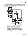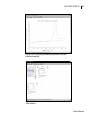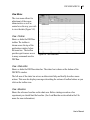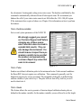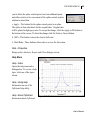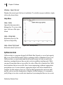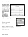
1
User’s Manual Model CSC 6300 Nano-Differential Scanning Calorimeter III Nano-Differential Scanning Calorimeter III, User’s Manual Revision 12405 Copyright ©2005 Calorimetry Sciences Corporation All Rights Reserved Printed in the United States of America. No part of the manual may be photocopied or reproduced in any form without the express written permission of Calorimetry Sciences Corporation. This manual is supplied “as is” without any warranty of any kind, and is subject to change without notice. Calorimetry Sciences Corporation shall not be liable for any technical inaccuracies, typographical errors, editorial omissions, any direct, indirect, or consequential damages resulting from the use of information contained in this manual. Technology Acknowledgements This product was developed in cooperation with Applied Thermodynamics. This product uses technology licensed from The Johns Hopkins University. Trademark Acknowledgements IBM™ and Personal Computer are registered trademarks of International Business Machines Corp. Microsoft™ and Windows™, are trademarks of Microsoft Corporation. All other products are trademarks or registered trademarks of their respective companies. Special Acknowledgements �� ���� ��� �� �� ������ Thanks to Dr. Kenneth J. Breslauer for his patience and editorial contributions. Thanks to Dr. Kenneth Murphy for his skillful editing and valuable input. Special thanks goes to Dr. Jens Völker for development of filling protocol for capillary cells. ������� Calorimetry Sciences Corp. 890 West 410 North, Suite A, Lindon, Utah 84042 USA www.calorimetrysciences.com CSC 6300 N-DSC III i Table of Contents CHAPTER ONE: INTRODUCTION........................................1 General Information................................................................1 Applications ..............................................................................1 Features.....................................................................................3 Safety Considerations ..............................................................3 Lifting and moving this equipment........................................3 CE Comments...........................................................................4 EMC Directive .......................................................................4 Immunity Testing ...................................................................4 Emission Testing ....................................................................4 Low Voltage Directive (Safety) .............................................4 Specifications ............................................................................5 Terminology..............................................................................5 CHAPTER TWO: INSTALLATION.........................................7 Product Items ...........................................................................7 Optional Items..........................................................................9 Unpacking and Inspection.......................................................9 Warranty.................................................................................10 Space Requirements...............................................................11 User’s Manual ii Table of Contents Ambient Temperature Requirements...................................11 Power Requirements..............................................................11 Purge Gas Requirements.......................................................11 Electrical Connections ...........................................................12 Software Installation..............................................................13 CHAPTER THREE: INSTRUMENT DESCRIPTION AND THEORY Overview .................................................................................17 Key design features ................................................................17 Theory of Operation ..............................................................18 Instrument Performance .......................................................21 The Baseline.........................................................................25 CHAPTER 4: CONDUCTING AN EXPERIMENT...............27 Starting up the N-DSC III.....................................................27 Experiment Overview............................................................27 Solution Preparation..............................................................28 Preparation of the Buffer Solution .......................................28 Preparation of Dilute Biopolymer Solutions........................28 Degassing the Buffer and Sample Solutions........................29 Run Baseline and Sample Solution Scans............................29 Filling the Cylindrical Cells.................................................30 Filling the Capillary Cells....................................................31 Calorimetry Sciences Corp. 17 CSC 6300 N-DSC III iii Cell pressurization and Checking for Bubbles.....................34 Cleaning the Calorimeter ......................................................35 Cylindrical Cell Design Flushing Equipment ......................37 Capillary Cell Design Flushing Equipment .........................37 Performing a Thermodynamic Analysis ..............................38 Analysis................................................................................38 Using the DSCRun Acquisition Program ............................48 Setting up an experiment ....................................................48 Starting an experiment .........................................................49 Saving the Data ....................................................................50 Excess Heat Capacity...........................................................50 CHAPTER 5: SOFTWARE .....................................................55 DSCRUN.................................................................................55 DSC Control Panel...............................................................55 Main Menu...........................................................................57 Edit Menu.............................................................................60 View Menu...........................................................................61 Run Menu.............................................................................62 Tools Menu ..........................................................................64 Help Menu ...........................................................................66 Zooming in on a particular part of the data........................68 User’s Manual iv Table of Contents DSCRun Operating Modes ...................................................70 Idle Mode .............................................................................70 Moving Temperature Mode .................................................70 Equilibration Mode ..............................................................70 Heating/Cooling Mode.........................................................70 Balance Mode and Residual Mode ......................................70 CpCalc ....................................................................................70 File Menu .............................................................................71 Edit Menu.............................................................................73 View Menu ..........................................................................75 Insert Menu ..........................................................................76 Options Menu.......................................................................78 Window Menu......................................................................79 Help Menu ...........................................................................80 CpExtract................................................................................80 File Menu .............................................................................81 Edit Menu.............................................................................83 View Menu...........................................................................84 Data Menu............................................................................85 Help Menu ...........................................................................89 CpConvert ..............................................................................90 Calorimetry Sciences Corp. CSC 6300 N-DSC III v File Menu .............................................................................90 Edit Menu.............................................................................92 View Menu...........................................................................93 Data Menu............................................................................94 Window Menu......................................................................99 Help Menu .........................................................................100 CpDeconvolute .....................................................................100 Main Window.....................................................................101 File Menu ..........................................................................102 Edit Menu ..........................................................................104 View Menu.........................................................................105 Window Menu....................................................................105 Data Menu..........................................................................106 Fit Menu.............................................................................108 Help Menu .........................................................................109 CHAPTER 6: SAMPLE EXPERIMENT ..............................115 Denaturation of Lysozyme ..................................................115 Sample Preparation .............................................................115 Loading the Buffer and Running a Baseline .....................116 Loading the Sample on the Fly ...........................................119 Data Analysis ........................................................................121 User’s Manual vi Table of Contents CHAPTER 7: THERMODYNAMIC MODELING ..............129 Determination of the Partial Specific Heat Capacity of Solute Molecule Deconvolution of the Partial Molar Heat Capacity ..........130 Analysis of Marginally Stable Proteins..............................133 CHAPTER 8: MAINTENANCE AND TROUBLESHOOTING135 Balance and Residual...........................................................135 Purging the N-DSC III ........................................................136 Fan Filter ..............................................................................138 O-Rings .................................................................................138 Cleaning ................................................................................139 Troubleshooting....................................................................140 Calorimetry Sciences Corp. 129 CSC 6300 N-DSC III 1 Chapter One: Introduction General Information The CSC Nano-Differential Scanning Calorimeter III (N-DSC III) is designed specifically for the measurement of absolute heat capacities of biopolymers in dilute solution. Developed by Applied Thermodynamics, the N-DSC III incorporates over 20 years of experience by Dr. Peter Privalov in DSC instrument design, computer control, and data analysis methods. The N-DSC III offers researchers an order of magnitude improvement in sensitivity and baseline repeatability. The instrument is a power compensation design using a completely solid-state thermostat and is equipped with fixed 24-K gold or platinum cylindrical or capillary cells. With an operating temperature range of -10 to +130°C (or +160°C for high temperature units), scan rates up to 2°C/min. in both the heating and cooling directions, and baseline repeatability of ±0.4 µcal/C @ 1°C/min. the N-DSC III can be used to study the thermal denaturation of many proteins with as little as 50 µg or less of sample. Applications The N-DSC III allows researchers to study almost any thermal transition occurring in dilute biopolymer solution in the temperature range of -10 to +130°C. It also offers researchers a new dimension in sensitivity, baseline noise, and baseline repeatability in both heating and cooling modes. The instrument’s ability to measure absolute heat capacities allows the researcher to examine biopolymer solution conformation and solvation as well as subtle changes in folding rather than just complete unfolding. This instrument is simply the best instrument available for studies of biopolymer thermal stability and the effects of biopolymer or ligand interactions on macromolecular structure. The baseline repeatability ensures that reliable ΔCp data can be obtained from a single User’s Manual 2 Chapter 1: Introduction scan. A graph of raw heat data versus temperature for a Barnase scan is shown in Figure 1-1. Typical uses for the N-DSC III include: • Biopolymer Solution Conformation & Solvation (Absolute heat capacities) • Biopolymer Stability (Protein denaturation) • Biopolymer Structure (Domain organization) • Bioengineering (Mutant proteins) • Ligand Interactions (Drug binding to proteins or nucleic acids) • Membrane Structure (Lipid Bilayers, membrane proteins) • Polynucleotides (Helix to coil transitions) Figure 1-1: Raw microwatt data for a heating scan of a typical protein. The sample was 60 µg of Barnase in 20 mM sodium acetate buffer at pH 5.5 (the scan rate was 1°C/min.). Calorimetry Sciences Corp. CSC 6300 N-DSC III 3 Features The N-DSC III is a fixed-cell power compensation design for the absolute maximum in baseline repeatability. The cylindrical or capillary cells can be pressurized up to 6 atmospheres for optimum performance over the entire temperature range. The cylindrical cell requires slightly less sample, while the capillary design minimizes thermal fluctuations or noise due to aggregation and precipitation. A solid state thermostat provides scanning in both the heating and cooling directions. The thermostat’s superior temperature control eliminates the need for an auxiliary cooling bath. The N-DSC III operates completely under the control of an external computer system. The data collection functions and the powerful data analysis programs run in Microsoft Windows and are compatible with other Windows programs. A sample of the N-DSC III analysis software is shown in Figure 1-2. Safety Considerations This equipment should only be used by personnel familiar with standard chemistry and laboratory operating procedures and practices. Lifting and moving this equipment This equipment is not portable nor was it designed as such. When moving the N-DSC III, to avoid the possibility of Figure 1-2: CpCalc worksheet displaying the analysis of Barnase data. User’s Manual 4 Chapter 1: Introduction damage to the instrument, solicit the help of an assistant. CE Comments EMC Directive This instrument has been tested to meet the European Electromagnetic Compatibility Directive (EMC Directive, 89/336/EEC). The Declaration of Conformity for your instrument lists the specific standards to which the unit was tested. The instrument was designed specifically as a test and measuring device. Compliance to the EMC directive is through IEC 6132601 Electrical equipment for measurement, control and laboratory use - EMC requirements (1998). As noted in the IEC 61326-1, the instrument can have varying configurations. Emissions may, in non-typical applications, exceed the levels required by the standard. It is not practical to test all configurations, as the manufacturer has no control over the user application of the instrument. Immunity Testing The instrument was tested to the requirements for laboratory locations. Emission Testing The instrument fulfills the limit requirements for Class A equipment but does not fulfill the limit requirements for Class B equipment. The instrument was not designated to be used in domestic establishments. Low Voltage Directive (Safety) In order to comply with the European Low Voltage Directive (73/23/EEC), Calorimetry Sciences (CSC) equipment has been designed to meet IEC 1010-1 (EN 61010-1) standards. Calorimetry Sciences Corp. CSC 6300 N-DSC III 5 Specifications CSC 6300 Nano-Differential Scanning Calorimeter III Specifications Response Time Halftime = 5 seconds Baseline Repeatability Standard Deviation ±4 µcal/°C at 1°C/minute Baseline Noise Standard Deviation ±0.015 µWatts Cell Construction Cylindrical in 24K gold or capillary in platinum Cell Volume 0.33 mL, nominal cylindrical or capillary Cell Pressurization Range 0 to 6 Atmospheres Temperature Scan Range -10 to +130°C (Standard Temp.) or -10 to +160°C (High Temp.) Temperature Scan Rate 0 to 2°C/minute (variable) Operating Altitude Sea level to 3,000 meters Ambient Operating Temperature Range 0 to 30°C Power Requirements 95-220 Volts at 3-5 amps, 50-60 Hz. Emissions Class Class A Dimensions (D x H x W) 53 cm (21 in.) x 32 cm (13 in.) x 38 cm (15 in.) Weight 9 kg. (20 lbs.) Table 1: 6300 N-DSC III Specifications. Terminology Access flange A round opening at the top of the instrument that accommodates the Access tubes. Access tubes The platinum tubes which connect the cells to the access flange and are used to fill or flush the cells with sample solutions or solvents. User’s Manual 6 Chapter 1: Introduction Balancing The process that automatically generates the Instrument baseline. Cell The N-DSC III design allows for 24-K gold or platinum cells in either a cylindrical or capillary design with nominal volumes of 0.33 ml. The instrument uses one sample and one reference cell. DEP (Data Exchange Ports) Method used to transfer data between objects in CpCalc. Instrument baseline An analytical approximation of the Water-Water baseline, which is stored by the N-DSC III software. The baseline may be automatically subtracted from the calorimetric signal displayed while performing a scanning experiment. LED A colored, status indicator lamp on the front panel of the NDSC III. The indicator LED displays the power on/off status of instrument. Pressure handle A removable cap used to seal the access flange prior to pressurization of the cells during operation. Reference baseline The buffer-buffer scan data that will be used as a baseline in the analysis of sample heat capacity data. The reference baseline can be downloaded to the DSCRun software program and subtracted from acquired data sample on a real-time basis. This subtraction results in a display of the apparent excess heat capacity but does not affect the stored data file. Scan A single run of the calorimeter from the lower temperature limit to upper temperature limit or vice versa. Time constant The response time of the instrument. Calorimetry Sciences Corp. CSC 6300 N-DSC III 7 Chapter Two: Installation Product Items Pressure Handle N-DSC III Computer System with Pre-Installed Interface Card Spill Plate User’s Manual and Software Figure 2-1: CSC Model 6300 N-DSC III System. The Model 6300 package includes the following items: • Model 6300 Nano-Differential Scanning Calorimeter III • Power cord for Model 6300 N-DSC III • Computer system and display monitor with accessories, factory-installed interface card, and all required software (These items may arrive in a separate shipment(s)). The computer system consists of current technology at the time of purchase, and uses the Miscrosoft Windows operating system. User’s Manual 8 Chapter 2: Installation Any hardware or software changes to this system other than those authorized by Calorimetry Sciences Corp. will void your warranty and may incur charges to return your system to factory specifications. • Surge protector plug strip (not included for 220V locations) • User’s guide (this manual) • Pressure handle and 1 replacement O-ring. • 2 ea. 1 ml filling syringe and six (6) filling needles (cylindrical cell instrument only) • N-DSC III cell cleaning adapter with silicone tubing (cylindrical cell instrument only) • 1 ml. Micropipette with tips and silicone tubing (capillary cell instrument only) • Six (6) feet silicone tubing for cleaning (capillary cell instrument only) • Vacuum degassing system • Windows-based Experiment Setup and Data Collection Software (This software was previously installed at the factory and is typically used for software reinstallation.) • Microsoft Windows Operating System (This software was previously installed at the factory and is typically used for software reinstallation.) • The following quick reference sheets: 1. N-DSC quick start 2. Filling the N-DSC 3. N-DSC Sample Tips 4. Benefits of Running the Residual Scan 5. Intense Cleaning After Protein Solutions 6. N-DSC Troubleshooting Calorimetry Sciences Corp. CSC 6300 N-DSC III 9 Optional Items The following items are available to complement your N-DSC III instrument: • Laser printer • Color printer • Additional filling needles • Replacement 1 ml syringe • Micropipetter and Micropipette tips • Replacement N-DSC III cleaning adapter • Replacement silicone tubing for cleaning adapter • Replacement Pressure Handle • Replacement pressure O-ring kit (package of 3) • Replacement spill plate Unpacking and Inspection Unpack your instrument components as soon as you receive them. Carefully inspect each component for shipping damage. If you note any damage, please notify the carrier immediately. User’s Manual 10 Chapter 2: Installation For additional help in assessing shipping damage or to report any missing or defective parts, contact: Calorimetry Sciences Corporation 890 West 410 North, Suite A Lindon, Utah 84042 (801) 763-1500 (801) 763-1414 FAX [email protected] (E-mail) www.calscorp.com (World Wide Web) Warranty Calorimetry Sciences Corporation warrants this product against defects in materials and workmanship for a period of two (2) years from the shipment date. Any product which proves defective during this stated warranty period will be repaired or replaced by Calorimetry Sciences Corporation. The foregoing warranty will not apply to defects resulting from: • Improper or inadequate maintenance, adjustment, calibration, or operation by the buyer; • Unauthorized modification or misuse (this shall include addition of software or other applications to the external computer that operates this system); • Operation outside the electrical and mechanical specifications of this product; • Improper site location, buyer-induced contamination, or leaks; • Failure to use proper surge protection; • Improper return packaging To exercise this warranty, please call or write Calorimetry Sciences Corporation. Calorimetry Sciences Corp. CSC 6300 N-DSC III 11 Space Requirements The N-DSC III requires at least 5' x 2' of bench space to accommodate both the instrument and attached computer system. Ambient Temperature Requirements For optimum performance of the N-DSC III it is recommended, but not required, that the ambient temperature of the operating environment should not deviate more than ±1°C, consisting of slow temperature changes. The N-DSC III should also be away from windows and out of the path of active heating or cooling vents or ducts. Power Requirements The N-DSC III requires a grounded, single-phase power source. A three-conductor line cord assures a safety ground. The operating voltage and line frequency are preset at the factory for either 120 or 220 V, 50/60 Hz operation based on your order configuration and power requirements. The N-DSC III calorimeter system requires one (1) 15 amp line for the instrument and computer system. All components of the system should be connected to a surge suppressor plug strip. Plug the surge suppressor power strip into an isolated power line. An isolated power line is one used only for electrical instruments (i.e.: no motors, compressors or heaters) that do not create a power surge upon start-up. All items should be connected to a surge suppressor plug strip. Purge Gas Requirements Because the N-DSC III is capable of running below room temperature, the calorimeter’s thermal shield may need to be purged periodically with a dry gas to remove any moisture inside the system. The purge procedure is described in Chapter 8, Maintenance and Troubleshooting and on the Troubleshooting quick reference sheet. The process involves evacuation of the canister with a vacuum pump followed by introduction of the dry gas. User’s Manual 12 Chapter 2: Installation Argon is preferred due to its low moisture content, but nitrogen is also acceptable. Do not run the calorimeter with the purge valve open. Electrical Connections Using the diagram shown in Figure 2-2 for reference, attach the connectors as indicated. Figure 2-2: N-DSC III interconnection diagram. 1. Make sure all of the equipment is turned off. 2. Make sure the power switch to the surge suppressor is in the OFF position. Calorimetry Sciences Corp. CSC 6300 N-DSC III 13 3. Plug the power cord of the N-DSC III assembly into a surge suppressor strip. 4. Assemble the computer system per the instructions included in its shipment carton. This basic connection information is also shown in Figure 2-2, however, your system may vary slightly from the figure shown. 5. Connect the calorimeter to the computer system as shown. 6. If you have ordered one of the two optional printers, attach it to the printer connector as shown in the diagram. 7. Ensure that airflow to the cooling fan on the bottom of the calorimeter is not blocked by bench back-splashes, walls, or other equipment. Software Installation All software required to operate the N-DSC III was preinstalled prior to shipment. We provide the steps below in the event that reinstallation of the software is necessary. Contact CSC before reinstalling the software. For detailed information on installation of the Windows operating system, refer to the information included with your Gateway computer system. To reinstall DSCRun (N-DSC III control software) or CpCalc (data evaluation software), place the distribution CD into the external computer system’s CD-ROM drive. From the Windows taskbar, select: 1. Start⇒Run 2. In the Command Line dialog box type: D:\SETUP 3. Click OK. Setup will install the program based on information you provide during the installation process. User’s Manual 14 Chapter 2: Installation An interface card installed in your computer system serves to convert data from the calorimeter into digital information used during data analysis. This interface card requires a special software driver. This driver was preinstalled at the factory. To reinstall the software driver on your system: 1. Insert the Nidaq Data Acquisition Driver Software CD-ROM into the computer system’s CD-ROM drive. 2. After a few seconds the computer system will recognize the presence of the driver software CD-ROM and the NI-DAQ installation screen will appear. Select the “NI-DAQ Driver Files (Minimum Install)” option. Click Next 3. The Destination Directory screen will appear. Click Next. 4. The Program Group dialog box will appear. Click Next. 5. At the Ready to Install! screen click Next. 6. The installation script will install the appropriate software drivers. 7. At the Restart prompt, click OK. 8. The system will restart. 9. After logging in, select Start⇒NI-DAQ For Windows⇒NI-DAQ Configuration Utility. 10. The configuration utility will automatically detect the presence of your interface card. At the Found New NI-DAQ Hardware prompt, click Yes. 11. The default settings that appear on the next few dialog boxes are correct. At the prompt, click Yes. 12. Upon completion of the parameter settings prompts, the interface card description will appear in the NI-DAQ device list. 13. Select File⇒Save 14. Select File⇒Exit Calorimetry Sciences Corp. CSC 6300 N-DSC III 15 15. Restart your system. 16. All required drivers are now installed on your system. User’s Manual 16 Chapter 2: Installation This page intentionally left blank. Calorimetry Sciences Corp. CSC 6300 N-DSC III 17 Chapter Three: Instrument Description and Theory Overview The N-DSC III is the most precise scanning calorimeter available for the study of the heat capacity of liquids in a broad temperature range. This scanning calorimeter operates differentially and is equipped with a pair of gold or platinum cells with semiconductor sensors. It scans up and down in temperature at user selected rates. The instrument is controlled by an external computer that also provides a full thermodynamic analysis of the results. The N-DSC III’s construction does not involve the use of organic compounds. This eliminates a source of baseline noise that has affected previous scanning calorimeters. The cells are designed to minimize temperature gradients in the heated/cooled liquid sample and permit easy washing and reloading without the introduction of air bubbles when loading. Measurements can be performed under a constant excess pressure (3 to 6 atm) which prevents formation of gas bubbles and boiling of aqueous solutions above 100°C. These features are crucial when determining the absolute heat capacities of solutions. The noise level of the recorded heating or cooling power difference signal is very low (baseline noise is ±0.015 µW standard deviation) with a response half-time of 5 sec. The reproducibility of the baseline after refilling is on the order ±0.4 µcal/°C at 1°C/min. Key design features The main difference in this instrument when compared to earlier biological scanning calorimeters is based on the method in which the heating and cooling of the cells is implemented. In previous scanning microcalorimeters the cell is heated with constant power and is followed in temperature by the thermal jacket (adiabatization system) in User’s Manual 18 Chapter 3: Instrument Description and Theory order to exclude heat exchange. In this instrument, the thermal jacket plays a leading role in the heating and cooling of the cells (Figure 3-1). The idea of using the thermal jacket as the driving heating force is not new in scanning calorimetry. It was implemented before in various instruments. In those instruments a massive copper jacket was heated electrically with constant power and the cells were heated passively by the heat flow from the jacket. If the heat capacity of the jacket is large and the heating power significantly exceeds the heat exchange with the environment, the temperature of the jacket will increase at a constant rate; however, the rate of cooling will be temperature dependent. Correspondingly, these previous instruments permitted measurement of heat capacity changes during heating but not cooling. Theory of Operation In the N-DSC III design (Figure 3-1a and Figure 3-1b) the thermal jacket (11) is heated and cooled at a constant rate. Using a known reference voltage, the temperature of the jacket is controlled by the computer. The temperature control circuit (3) compares this reference voltage to that of the platinum thermometer (1) inside the calorimeter block. After comparison, the computer adjusts the power applied to the Heating and Cooling Peltier elements (4). Thus, through the Digital to Analog Converters (5), the computer has a direct linear control of the temperature of the jacket. This ensures the cells (6/7) are heated and cooled at a constant rate. For practical reasons however, the maximum heating or cooling rate of the N-DSC III is limited to 2°C/minute. The minimum temperature scan rate is actually 0°C/time (isothermal). Another important feature of the N-DSC III is the use of semiconductor thermoelectric batteries as sensors (8). Since semiconductor thermoelectric batteries have larger temperature coefficients than their bi-metal counterparts, they are also temperature dependent. To avoid these problems, the N-DSC III uses a power compensation design. The temperature difference between the two cells, measured by the semiconductor thermoelectric battery (8) and amplified by the signal amplifier (14) is maintained near zero by applying an appropriate power difference to the two cells using electric heaters Calorimetry Sciences Corp. CSC 6300 N-DSC III 19 (9, 10). The heaters are attached directly to the cell body and controlled by a feedback control algorithm (12) and power compensation bridge (15). This power difference is also recorded as the signal by the computer (13). Figure 3-1a: N-DSC III block diagram. Dashed rectangle represents the components implemented in software. 1- Platinum thermometer; 2- temperature control block; 3-temperature measuring circuit; 4-Heating and Cooling Peltier elements; 5temperature control algorithm; 6, 7- cylindrical measurement cells; 8-thermosensor; 9, 10- power compensation heaters; 11-jacket; 12- feedback control algorithm; 13- data file; 14- signal amplifier; 15- power compensation bridge; 16- manostat; 17- pressure sensor; 18- pressure gauge. User’s Manual 20 Chapter 3: Instrument Description and Theory Figure 3-1b: N-DSC III capillary cell measuring unit. Items 6 and 7 designate capillary cells. The use of semiconductor thermobatteries as sensors required a new design for the construction of the calorimetric cells. The N-DSC III’s cells are made from 24 karat gold or platinum. Both types have platinum access tubes. Cylindrical cells (6,7 in Figure 3-1a) are machined as a cylinder and capped at each end. Capillary cells (6,7 in Figure 3-1b) are made of wound capillary tubing. Access tubes are open to the manostat which maintains a constant excess pressure. The sensors and balancing heaters (resistors) are soldered to the surface of the cells. The heating of the cells is provided by the heat flow through the access tubes via thermal contact with the jacket. The temperature of the jacket is measured by the platinum thermometer and is monitored by the computer. The excess pressure in the manostat Calorimetry Sciences Corp. CSC 6300 N-DSC III 21 (16) is adjusted by the position of a piston inside the instrument body. Cell pressure is measured by a piezoelectric sensor (17), converted to a digital signal and displayed on the computer monitor. The excess pressure (up to 6 atmospheres) is sufficient to allow heating of aqueous solutions up to 130°C (160°C for high temperature units) without appearance of gas bubbles and boiling. In the ideal DSC the thermal properties of the Sample and Reference cells would be exactly identical. The ideal instrument, filled with water in both cells would yield a zero power baseline. Due to a variety of technical difficulties the ideal match between the two cells is never achieved in a real DSC. Cell differences result in differences in the heating and cooling baselines. To minimize this problem additional power must be provided to compensate for the differences in cell properties. In the N-DSC III this additional power is automatically calculated by the computer during the first calibration (or balancing) run of the instrument. All elements of the N-DSC III (as shown in Figure 3-1) are contained within a single, integrated package. The N-DSC III is completely self-contained and does not require accessory cooling baths or other water supplies. The N-DSC III does not require a special operating environment and is not sensitive to typical variations in room temperature and humidity. Instrument Performance The N-DSC III yields reproducible baselines as demonstrated by performing heating/ cooling scans of buffer or protein solutions. Figure 3-2 displays consecutive baselines obtained in heating and cooling scans of 20 nM sodium acetate, pH 5.5. As indicated in the figure, the noise level is ±0.015 µWatts standard deviation. More importantly, the standard deviation between repeated scans obtained after loading the calorimeter was ±0.4 µcal/°C at 1°C/min. For measurements of the absolute heat capacity of a solution, the key specification is the reproducibility of baseline recordings after refilling the cells. This characteristic permits accurate measurements of the difference in heat capacity between solution and User’s Manual 22 Chapter 3: Instrument Description and Theory solvent and, consequently, the partial molar heat capacity of solute. Tests using degassed water show the N-DSC III’s baseline reproducibility (after refilling the cells) is of the same order of magnitude as the reproducibility obtained without refilling the cells. For buffer solutions it is often true that some conditioning is necessary to obtain the highest reproducibility. The heating scan data shown Figure 3-2: Baseline reproducibility demonstrated in the in Figure 3-3 illustrate real heating and cooling scans for three separate fillings of both differences in the absolute the sample and reference cells with 20 nM sodium acetate, pH 5.5. heat capacity of the barnase solution and the acetate buffer. Because the heat capacity of the barnase protein is smaller than the heat capacity of the displaced water, the absolute heat capacity of the barnase solution is below the buffer solution heat capacity at all temperatures below or above the range during which the protein exhibits an excess in heat capacity due to the enthalpy change for the unfolding (denaturation) process. In order to accurately determine the partial molar heat capacity of a solute, in this case the protein, it is necessary to be able to subtract absolute heat capacity data for the solvent from the solution. Figures 3-4a and 3-4b show the standard deviations obtained for the three buffer scans and the three protein scans shown in Figure 3-3. These data illustrate the repeatability required to obtain partial molar heat capacities for biopolymers in dilute solutions. Calorimetry Sciences Corp. CSC 6300 N-DSC III 23 Figure 3-3: Three different scans of Barnase superimposed on one another along with the three buffer scans shown in Figure 3-2. These experiments demonstrate the reproducibility between scans after refilling. The average standard deviation was ±0.025 µW. Also important to note is the noise level on the order of ±0.015 µW standard deviation. The variation in the temperature of the peak is within 0.05K. User’s Manual 24 Chapter 3: Instrument Description and Theory Baseline Standard Deviation 3 Buffer Scans 0.2 0.0461 0.0361 0.15 0.1 µWatts µcal/sec 0.0261 0.0161 0.05 0.0061 0 -0.0039 -0.05 -0.0139 -0.0239 -0.1 20 30 40 50 60 70 Temperature °C Figure 3-4a: The standard deviation of the three different scans of 20 nM sodium acetate, pH 5.5. Standard deviation was calculated for each point on the temperature scale. Standard Deviation 3 Barnase Scans 0.2 0.0461 0.0361 0.15 0.1 0.0161 0.05 0.0061 µWatts µcal/sec 0.0261 0 -0.0039 -0.05 -0.0139 -0.0239 -0.1 20 30 40 50 60 70 Temperature °C Figure 3-4b: The standard deviation of the three different scans of 60 µg of Barnase in 20 nM sodium acetate, pH 5.5. Standard deviation was calculated for each point on the temperature scale. Calorimetry Sciences Corp. CSC 6300 N-DSC III 25 The Baseline Although a differential scanning calorimeter is designed for the measurement of the difference in heat capacities of two liquids (solvent and sample solutions), this cannot be done with sufficient accuracy in a single experiment in which one of the cells is loaded with one liquid (solvent) and the other cell with another (sample solution). For difference heat capacity determinations, it is necessary first to load both cells with solvent and to determine the baseline of the instrument over the entire required temperature range. This baseline is usually not completely linear nor close to zero. The measuring unit of the N-DSC III contains two cells that are closely matched in both mass and internal volume. These cells are attached to the calorimeter block via access tubes. During the manufacture of the calorimeter these access tubes were machined to match the thermal conductivity of the sample and reference cells. If it were possible to exactly match cell masses, volumes and thermal pathways then the instrument baseline would be zero over the entire scan range. However, the small differences that exist cause the instrument baseline to be both non-zero and slightly curved. Although the baseline is reproducible and could be used without further adjustments, the signal slope and curvature make it difficult to see small changes in excess heat capacity during data collection. The N-DSC III data collection software contains two features used to bring the signal onto a more reasonable scale for viewing. The main feature, termed a balance, fits both the up and down scans to a second order polynomial. The calculated correction is then used to adjust the power compensation signal. For more information on running a balance refer to Chapter 8. The balance may need to be rerun periodically. The second feature, termed a residual scan, fits both the up and down scans to a series of polynomials. The resulting fits are mathematically subtracted (as opposed to being used to adjust the power compensation signal) from the heat flow signal. For the best results, a new residual needs to be run for each scan rate (i.e. a residual for a 1°C/minute scan, another for a 0.5°C/minute scan, etc.) Generally, the residual scan is used for cosmetic reasons only since the heat capacity data is obtained by subtracting a buffer thermogram from a sample thermogram. For more information on running a residual scan refer to Chapter 8. User’s Manual 26 Chapter 3: Instrument Description and Theory The baseline obtained for the given solvent can be automatically subtracted from the results of scanning solutions of solutes (sample solution) with the same solvent. In that case the recorded deviation from zero will correspond to the difference in heat capacity between the studied sample solution and the solvent throughout the entire temperature range. Calorimetry Sciences Corp. CSC 6300 N-DSC III 27 Chapter 4: Conducting an Experiment Starting up the N-DSC III Once you have completely set up the calorimeter and computer system (see Chapter 2) you are ready to begin an experiment. Turn on the surge suppressor power switch and the computer system and monitor. The computer system shipped without a password; if prompted you can simply push the return key to open Windows. If you wish to create a password see the documentation for Windows. Turn on the power switch to the calorimeter. It is located on the back panel and the front LED will light up green when in the “on” position. You are now ready to begin an experiment. Experiment Overview A typical N-DSC III experiment involves the following: • Preparation of the Buffer/Solvent and Biopolymer Solutions • Running the Baseline and the Sample Solution Scans • Cleaning the Calorimeter • Performing a Thermodynamic Analysis Each step is briefly described here. Additional information is provided in Chapter 6: Sample Experiment. It is assumed that the N-DSC III user is familiar with standard laboratory procedures and techniques. It is critical that the N-DSC III cells be cleaned immediately at the end of each experiment. Although the calorimeter can be left idle with water-filled cells at 25°C when not performing experiments, it will generally perform better when it is left continuously scanning. This is done by filling the cells with deionized degassed water and scanning up and down continuously between the upper and lower temperature limits at 1°C. User’s Manual 28 Chapter 4: Conducting an Experiment Solution Preparation There are three basic procedures associated with the preparation of the buffer and sample solutions. These are outlined in the following steps. Preparation of the Buffer Solution The solvent systems used for the preparation of dilute biopolymers are typically buffered aqueous solutions which often contain strong supporting electrolytes (e.g. NaCl or KCl) to adjust the ionic strength. Buffers are typically prepared by weighing an appropriate amount of the acidic or basic form of a weak acid (or weak base) into a measured volume of deionized water. The pH of the buffer is then adjusted to the desired value by adding either strong acid (e.g. HCl) or a strong base (e.g. NaOH) while monitoring with a pH meter. Since the buffer will be used in several different ways (rinsing the calorimeter's cells, conditioning the cells, measurement of the calorimetric baseline, and dialyzation of the sample), it is generally a good idea to prepare a rather large volume of buffer (e.g. 1 liter or more). Be sure that you save enough of the dialyzed buffer to perform these procedures (50 ml or more). See Chapter 6 for detailed information on how to perform dialysis of a sample. Note that buffers used in DSC experiments should be carefully chosen to meet the following criteria: • The pKa should be as independent of temperature as possible (i.e. the ∆H for proton ionization should be small). This will keep the pH fairly constant during the course of the scan. • The components of the buffer/solvent solution should be thermally stable (i.e. the buffer should not precipitate or degrade in the temperature range of interest). Preparation of Dilute Biopolymer Solutions The concentration of the biopolymer should be chosen in a manner that will allow the user to optimize the amount of thermodynamic information. In the case of a typical protein, good heat capacity data can usually be measured for solutions with protein concentrations in the 0.2 mg/ml to 5 mg/ml range. When possible, information regarding the optimum concentration and solution conditions for DSC studies for specific biopolymers should be taken from the literature. A minimum volume of 0.5 ml Calorimetry Sciences Corp. CSC 6300 N-DSC III 29 of dilute protein solution is required to fill the N-DSC III cylindrical cell. About 1.2 ml is required to fill a capillary cell. Typically a protein solution will be prepared by weight or by dilution of a concentrated stock solution. For the best results, the protein (or other biopolymer sample) should be dialyzed prior to a DSC experiment and the dialysate should be used for the reference solution. It must be noted that high sensitivity DSC studies can only be done with highly purified biopolymers. Accepted techniques should be used for sample purification prior to solution preparation and dialysis. It is critical to know the solute (biopolymer) molecular weight, concentration and state of oligomerization prior to attempting a thermodynamic analysis of the heat capacity data. Degassing the Buffer and Sample Solutions Typically, if a solution is heated, gas bubbles will form as the solubility of dissolved gases (e.g. 02 and N2) is decreased with increasing temperature. If gas bubble formation occurs in the DSC cells during the run, the resulting heat capacity data will be noisy. This will be due to abrupt changes in the apparent heat capacity as a result of bubble driven liquid displacement effects. To minimize the possibility of gas bubble formation during the run, all reference and sample solutions must be degassed prior to being loaded into the DSC. Degassing is accomplished by simply pulling a vacuum of 0.3-0.5 atm on the solutions for a period of 10-15 minutes. An accessory degassing system consisting of a small rotary vane vacuum pump and a vacuum chamber desiccator is available from CSC if you do not have the appropriate equipment in your laboratory. Note that gas bubble formation during the run is retarded by the cell overpressure (up to 3-6 atm) provided by the DSC manostat. However, it is still necessary to remove the atmospheric gasses from the solutions. Run Baseline and Sample Solution Scans The second major step in conducting an experiment, which includes running the baseline and sample scans, is comprised of several sub-steps. There are two protocols for filling the cells depending on the type of N-DSC III cell design. Cylindrical cells utilize a syringe while capillary cells require a pipette. User’s Manual 30 Chapter 4: Conducting an Experiment Filling the Cylindrical Cells Equipment Required: 1 ml Hamilton syringe with 20 gauge needle Filling Procedure The cell filling procedure is one of the most important parts of conducting a DSC experiment and should be done with extreme care. The objective is to fill the cell with the appropriate solution without introducing any air bubbles. Even the smallest bubble can result in heat capacity data that is erratic and offset. You will need a 1 ml Hamilton syringe equipped with a 20 gauge needle (This needle and syringe are supplied with your Figure 4-1: Inserting the syringe into the cell reservoir. instrument). Before you begin filling the sample and reference cells, make sure that the cells are empty. Starting with the reference cell (leftmost access tube as viewed from the front of the DSC), begin by filling the syringe with approximately 0.5 ml of solution. You may find that larger volumes make the procedure easier but it is possible to load the cell correctly with the lesser amount. Remember to be careful not to trap any air bubbles. Insert the syringe into the reference cell and load the calorimeter in the following manner (Figure 4-1): 1. Position the needle (initially) so that it lightly touches the bottom of the reference cell (left access tube). 2. Raise it off the bottom approximately 1/16" 3. Gently inject the solution into the cell until you see it coming out of the access tube Calorimetry Sciences Corp. CSC 6300 N-DSC III 31 (Figure 4-2). 4. Slowly pump in and out about 0.1 ml of solution (a number of times) and watch to see if bubbles are coming out of the access tube. Perform this operation until it is apparent that there are no bubbles in the cell. At this point, slowly withdraw the needle from the access tube while simultaneously injecting solution to clear away any bubbles trapped by the needle. 5. When you are finished, the reservoir located at the top of the access tube should be filled about halfway with solution. Repeat the entire process to fill the sample cell (right access tube). In the case of a baseline run, the sample cell will be filled with the same solution (buffer dialysate) that was placed in the reference cell. In the case of the sample run, the sample cell will be filled with the dialyzed protein (or other biopolymer) solution. Figure 4-2: Carefully insert the syringe into one of the cells so that the needle lightly touches the bottom. Move the syringe slightly up off the bottom before performing the filling procedure. Note that additional care must be taken since proteins and other biopolymers have a tendency to foam when manipulated with a syringe. Filling the Capillary Cells Equipment Required: Adjustable 500-2500 µl pipette (Eppendorf Series 2000); Tubing-1/16" ID Manosil silicone rubber Be sure that the samples have been properly degassed. User’s Manual 32 Chapter 4: Conducting an Experiment Displace any residual liquid from the cells by blowing them out with an inert gas (N2) at low pressure. Figure 4-3: Placement and cutting of the silicon tubing on the pipette tip. Figure 4-4: The completed pipette tip. Filling the cells requires extreme care. The objective is to fill the cell with the appropriate solution without introducing any air bubbles. You will need an adjustable volume pipette with the volume set between 1200-1500 µl. You will also need four clean pipette tips and four short lengths (approx. 0.5 inch) of 1/16 inch I.D. Manosil silicone rubber tubing. 1. Prepare the Pipette Tips in the following manner. The disposable plastic tips used with the micropipette for loading and cleaning the DSC cells must be fitted with a short (approximate 0.5 inch long) length of Manosil silicone tubing to interface with the cell access tubes. Figures 4-3 and 4-4 illustrate how to trim and prepare the pipette tips. A length of the appropriate silicone tubing is provided with each calorimeter. Additional tubing can be ordered through your laboratory supplier or Calorimetry Sciences. 2. Before you begin filling the sample and reference cells, make sure that the cells are Calorimetry Sciences Corp. CSC 6300 N-DSC III 33 empty. Starting with the reference cell (leftmost pair of access tubes as viewed from the front of the DSC), attach one pipette tip to the outlet tube (located toward the back of the instrument) as shown in Figure 4-5. 3. Attach the second pipette tip to the pipette and fill it with from 1200 to 1500 µl of the reference solution (buffer dialysate). Attach the silicone extension of the pipette tip to the inlet access tube (See Figure 4-6) of the reference cell (front tube on left side of access flange) and fill the cell slowly (10-15 sec.) by gently depressing the pipette plunger. 4. After the cell is completely filled and you see solution emerge from the outlet access tube into the empty pipette tip, hold the outlet pipette tip vertical and make a few short strokes with the pipette plunger to gently force solution back and forth through the capillary cell. This technique helps to get rid of any bubbles that might still be trapped in the capillary channel. 5. As you are pushing the solution back and forth through the capillary be careful not to introduce air bubbles into the cell by letting either pipette tip go dry. After you are satisfied that the reference cell is free of bubbles, remove the pipette tips and pipette from the inlet and outlet access tubes. Minimize solution spillage by covering the open end of the free pipette tip with your thumb while removing it from the access tube. Figure 4-5: Attachment of the pipette tip to the access tube. Figure 4-6: Attachment of the pipette and silicone tubing to the access tubes of the reference cell. Repeat the entire process to fill the sample cell (rightmost pair of access tubes). In the case of a baseline run, the sample cell will be filled with the same solution (buffer dialysate) that was placed in the reference cell. In the case User’s Manual 34 Chapter 4: Conducting an Experiment of the sample run, the sample cell will be filled with the dialyzed protein (or other biopolymer) solution. Proteins in solution have a tendency to foam when manipulated with a pipette. Figure 4-7: Placement of the black vinyl caps on the rear access tubes. After both the reference and sample cells have been loaded and the pipette tips removed, the outlet access tubes for both cells (located toward the back of the access flange) must be capped with the small black access tube cap (see Figure 4-7). Remove excess liquid from the access tube area using suction or a lab tissue. Cell pressurization and Checking for Bubbles The last step in loading the cells is to attach the pressure handle to the access flange. To attach the pressure handle to the flange, screw the threaded ring onto the access flange tightly as shown in Figure 4-8. Do not pressurize the cells at this time. Open the DSCRun program by double clicking the DSCRun icon located on the Windows desktop (if it is not already running). Note that the N-DSC III must already be powered on before Figure 4-8: Attaching the pressure handle. opening DSCRun. Before beginning an experiment you must wait for the loaded solutions to thermally equilibrate with the calorimeter. Equilibration is complete when the µW reading (as shown on the Output Box of the computer display monitor Figure 4-9) settles to constant value. The next step is to adjust the manostat pressure to a value of at least 3 atm (up to 6 atm for high-temperature instruments) which is preset by the user in Tools⇒Runtime variables (see Chapter 5: Software). Calorimetry Sciences Corp. CSC 6300 N-DSC III Increase the pressure by clicking on the up-arrow in the DSCRun program (Figure 410) while monitoring the manostat pressure as displayed on the computer monitor (Figure 4-9). If a bubble is present the µW reading will exhibit a significant change (in excess of 30 µW) as the pressure is increased from 0 to 3 atm. If bubbles are indicated by an unstable µW reading as the cell overpressure is applied, the cells must be refilled using the procedures outlined previously. If you see little or no effect, proceed to the next step. 35 Figure 4-9: DSCRun screen: note the position of the pressure and µWatt output readings. Set the experiment parameters and start the scans. See “Using the DSCRun Acquisition Program” later in this chapter for more information. Cleaning the Calorimeter The final step in any experiment is cleaning the calorimeter. The N-DSC III is an extremely sensitive instrument which will only Figure 4-10: The up-arrow pressurizes the system, and the down-arrow is used to depressurize. User’s Manual 36 Chapter 4: Conducting an Experiment perform as specified if kept scrupulously clean. We recommend that the cells be washed at the completion of every experiment, i.e. after the baseline and sample scans are both completed for a specific experiment. The general procedure for cleaning the DSC cells with formic acid is described below. More vigorous cleaning is accomplished by following the procedures described in Chapter 8: Maintenance and Troubleshooting. The calorimeter should be cleaned immediately after an experiment. When the calorimeter is idling at approximately 25°C, Figure 4-11: Cylindrical cell cleaning adapter and cross sectional view of it is safe to reduce the cell pressure to zero. cleaning flow. Click down-arrow and remove the pressure handle from the access flange when depressurization is complete. If you have a cylindrical cell the 1 ml syringe is used to remove the solutions from the cells. With the capillary design you must first remove the cell outlet tube caps and then empty the cells with the pipette. To clean the cells, fill them with the recommended cleaning solution (50% formic acid) and run one scan cycle from 25 to 80°C at 1°C per minute. Caution: The pressure handle should not be attached to the calorimeter during cleaning. You should leave the small black caps off (if capillary cell) and the pressure handle off during these procedures. Rinse thoroughly all areas that come into contact with corrosive chemicals. Don't let any solutions pool inside the access tube area. Calorimetry Sciences Corp. Figure 4-12: Orientation of the cylindrical cell flushing apparatus. CSC 6300 N-DSC III 37 Following the formic acid wash, rinse the cells with a generous volume of high quality deionized water using the appropriate equipment for your cell design. Figure 4-13: Cylindrical cell cleaning apparatus for the flushing of large volumes of liquid through the cells. Cylindrical Cell Design Flushing Equipment The cylindrical cell cleaning adapter (Figure 4-11) is placed into the calorimeter's cells as shown in Figure 4-12 and Figure 4-13. The inlet tubing is placed in a large volume of water and the outlet tube is attached to a vacuum pump trap flask. This will allow you to flush large volumes of liquid through the cell. Capillary Cell Design Flushing Equipment Manosil silicone tubing is attached to the access tubes for Figure 4-14: Capillary cell cleaning apparatus for the each cell in the calorimeter, flushing of large volumes of liquid through the cells. one side is connected to a large flask of water and the other side to a vacuum pump trap flask as shown in Figure 4-14. This allows a large volume of solution to be drawn through the calorimeter's cells. If the formic acid rinse appears inadequate, (as judged by noisy water/water baseline scans), follow the intense cleaning procedure as described in Chapter 8. User’s Manual 38 Chapter 4: Conducting an Experiment Performing a Thermodynamic Analysis The thermodynamic analysis is conducted in the program known as CpCalc. This program allows you to calculate the partial molar and excess heat capacities of the biopolymer. Afterwards, the data can be fit to a series of models that are appropriate to the system being studied. In this section a simple overview of the operation of CpCalc will be described. For more detailed information see Chapter 5 and Chapter 6. Analysis Close the DSCRun acquisition program. Start the CpCalc program from the Nano-DSC program group. Select Insert⇒Data file from the main menu. Select a scan data file (Figure 4-15). In this set of example data, we used the "load on the fly" procedure so the buffer and sample scans are contained in the same file. After selecting the file, all scans for the data will be shown on the graph. The example we use is that of a lysozyme experiment taken from the Sample Experiment located in Chapter 6. Change the scale by selecting View⇒Scale. From the main menu put in the desired X and Y values (Figure 4-16). Press ESC to return to the main CpCalc worksheet (see Figure 4-17). Move the object insertion point (the small cross on the worksheet) to a position that is clear of other objects by positioning the mouse pointer over the new point and clicking the left mouse button once. Figure 4-15: Loading a scan file into CpCalc. Calorimetry Sciences Corp. Figure 4-16: Setting the data scale. CSC 6300 N-DSC III 39 Figure 4-17: CpCalc worksheet. Select Insert⇒Converter object from the main menu (Figure 4-18). Position the mouse pointer above the #3 output data exchange port (DEP) on the Buffer-Sample scan object (the arrow pointer will show a pipette being held by a hand). Click the left mouse button once, position the pointer above the #1 input DEP on the converter object, then click the left mouse button once more. This will insert the sample scan into the converter object (Figure 4-19). Note that if you did have separate sample and buffer scan files you would simply need to open them both on the CpCalc worksheet and transfer the data accordingly. Now in the same manner as the sample scan position the mouse pointer above the #1 output DEP on the Buffer-Sample scan . Click the left mouse button once, position the pointer above the 2 input DEP on the converter object, then click the left mouse button again. These two transfer operations have inserted the sample and buffer files into the converter object (Figure 4-20). The converter object is used to perform several different operations: 1) to subtract the buffer scan, 2) calculate the partial molar heat capacity, 3) perform baseline subtractions yielding the excess heat capacity and 4) calculate the calorimetric enthalpies from the User’s Manual 40 Chapter 4: Conducting an Experiment Figure 4-18: Positioning the object insertion point and inserting a converter object. Figure 4-19: CpCalc worksheet with sample file transferred into the Converter object. Calorimetry Sciences Corp. CSC 6300 N-DSC III 41 Figure 4-20: CpCalc worksheet with sample and buffer scans transferred into the Converter object. area under the excess heat capacity curve. See Chapter 5 for details on these functions. Position the mouse pointer over the converter object and double click the left mouse button. This will open the converter object for manipulation. Select Data⇒Convert to MHC from the main menu (Figure 4-21). Select the Temp Range and Convert to Molar Heat Capacity boxes. Next, input the temperature range (5 to 84°C), protein concentration (1.06 mg/ml), molecular weight (14.3 kd for HEW lysozyme) and the cell volume (0.3268 ml), then select OK. Select Data⇒Baseline⇒Linear-Polynomial from the main menu. Using the circles on the lines, fit the generated linear baseline (line with two circles) to the pre-transition experimental baseline and the generated polynomial baseline (line with three circles) to the experimental post-transition baseline (Figure 4-22a, b). Select View⇒Legend to display an estimate of calorimetric enthalpy, entropy and melting temperature (Figure 422c, d). Since the denaturation of lysozyme is nearly a two-state reversible process these values should compare well with those obtained by fitting to the appropriate model. This User’s Manual 42 Chapter 4: Conducting an Experiment Figure 4-21: Converting the raw data to molar heat capacity. will be done later. Press ESC to return to the CpCalc worksheet. Move the object insertion point (the small cross on the worksheet) to an open point on the CpCalc worksheet by positioning the mouse pointer over a clear area and pressing the left mouse button. Select Insert⇒Deconvolution from the main menu. Position the mouse pointer above the #1 output DEP on the converter object (Figure 4-23). Click the left mouse button once, position the pointer above the #1 input DEP on the deconvolution object, then click the left mouse button once (Figure 4-24). This will insert the molar heat capacity data into the deconvolution object (Figure 4-25). Position the mouse pointer over the deconvolution object and double click the left mouse button. This will open the deconvolution object. Make sure that the General Model is selected, then input the following initial guesses for the variables: Tm = 65°C, ∆H = 120 (kcal/mol), and ΔCp = 1.5 (kcal/(K-1 mol-1) (Figure 4-26). For this experiment you can leave the b and c coefficients for the temperature dependence of the heat capacity change as they are. These values are calculated from a large basis set of small globular proteins. Next, select Data⇒Static variables... from the main menu. Input the correct molecular Calorimetry Sciences Corp. CSC 6300 N-DSC III Figure 4-22a Figure 4-22c 43 Figure 4-22b Figure 4-22d Figure 4-22 a,b: Selection of a linear-polynomial baseline; and Figure 4-22 c,d: Display of the calorimetric enthalpy, entropy and baseline estimation. weight (kd), then change the A[0] (y-intercept) and A[1] (slope) coefficients if needed until the pre-transition estimated data and native state protein data overlay (Figure 4-27). When finished select OK. In this experiment we only needed to change the molecular weight. You may wish to alter the A[0] (y-intercept) and A[1] (slope) values to see how sensitive they are to changes. User’s Manual 44 Chapter 4: Conducting an Experiment Figure 4-23: Positioning of the pointer for the transfer of the molar heat capacity from the converter object. Figure 4-24: Positioning of the pointer for the transfer of the molar heat capacity to the deconvolution object. Calorimetry Sciences Corp. CSC 6300 N-DSC III 45 Figure 4-25: Both the experimental molar heat capacity and default theoretical estimate as they appear in the deconvolution object. Figure 4-26: Both the experimental partial molar heat capacity and an estimate of the theoretical fit presented in the deconvolution object. User’s Manual 46 Chapter 4: Conducting an Experiment After making your estimates of the fit, select Fit⇒Fit model from the main menu to perform the fitting operation (Figure 4-28). The values obtained from the analysis (∆H kcal/mol, ∆Cp kcal/(mol·K) and Tm (°C) compare well with those Figure 4-27: Static variables found in the literature for a two-state fit of lysozyme. It is dialog box. apparent however that there is a pre-transition (Figure 4-28) requiring the introduction of another state into the model. This pre-transition has been well characterized in the literature. To fit this additional transition select trans 2 which is located in the top middle section of the deconvolution object . Be sure you are still using the General model (4-29). Input the following initial guesses for the variables: Transition 1 Tm = 55°C ∆H = 12 kcal/mol ∆Cp = 0.3 kcal/mol⋅K Transition 2 Tm = 65°C ∆H = 115 kcal/mol ∆Cp = 1.5 kcal/(mol⋅K) Figure 4-28: Fit of the data using a one transition (two-state) reversible model. When you have entered all of the parameters, fit the data by selecting Fit⇒Fit model from the main menu (Figure 4-30). The values obtained may vary slightly for your particular experiment due to a number of factors. The largest concern is the number of parameters being fit. It may be necessary to Calorimetry Sciences Corp. CSC 6300 N-DSC III 47 Figure 4-29: Selecting a model with two reversible two-state transitions. Figure 4-30: Fit of the lysozyme solution assuming two reversible transitions (3 states). User’s Manual 48 Chapter 4: Conducting an Experiment fix some of the values to obtain results that are reasonable. Table 2 displays some typical results. Table 2 Using the DSCRun Acquisition Program Before you begin the experiment you must set the experimental parameters (low temperature limit, high temperature limit, temperature scan rate, number of cycles, etc.). Setting up an experiment Select RUN⇒Set Run Options from the main menu (Figure 4-31 and Figure 4-32). Set the following options: 1. Temperature Limits = 0 and 85°C 2. Direction = Heating 3. Rates = 1°C/min for both heating and cooling 4. Scans to Run = 4 5. Type in a File Name and Select the Save Data automatically box, then fill out the Attributes as desired. 6. Select OK to store the settings. Calorimetry Sciences Corp. CSC 6300 N-DSC III Figure 4-31: Setting the Buffer-Sample run options. 49 Figure 4-32: The Sample run options dialog box. Starting an experiment Start the scans by selecting Run⇒Start from the main menu (Figure 4-33). The instrument will scan down at 1°C per minute to 0°C. It will then equilibrate for 10 minutes before beginning to scan up at 1°C per minute (scan 1). When it reaches 85°C it will again begin to equilibrate at this temperature (10 minutes) then scan down at 1°C per minute (scan 2). Scans three and four will continue in the same manner. The time required to complete an experiment can be estimated by the following formula: Figure 4-33: Starting the DSCRun program. T − T Time (min .) = Time (Move Temperature) + 2 1 + 10 × N Scan Rate User’s Manual 50 Chapter 4: Conducting an Experiment where Time (Move Temperature) is the time it takes to move from the idle temperature to the initial scan start temperature, T2 and T1 are the upper and lower temperature limits respectively, Scan Rate is the average of the heating and cooling scan rates (they may be different) in °C/minute, and N is the number of scans requested. Note that the value of 10 on the right side of the equation represents the equilibration time before each scan. This value will be different if the equilibration time for the experiment is changed. Saving the Data There are three ways to save when the scans are finished. You can check the “Save Data automatically” box when setting the run options. You can also select File⇒Save or File⇒Save As from the main menu. To view previously run data during an experiment simply minimize the DSCRun screen and open CpExtract. Details of how to use CpExtract are given in Chapter 5: Software. Excess Heat Capacity In many experiments it is not possible to obtain the partial molar or absolute heat capacity of a biopolymer. The effect can be due to several factors including buffers that do not behave well when scanning, low biopolymer concentrations, samples that react or aggregate, an inability to match the ionic strengths and pH’s of the sample and reference cells, etc. In these cases the user should obtain the excess heat capacity and fit the data as described below. Again we use the lysozyme experiment to illustrate this effect. Begin by completing the first four steps of the analysis section. Select Data⇒Baseline⇒Polynomial from the main menu. Using the circles on the line, fit the generated polynomial (line with the circles) baseline to the pre-transition experimental baseline (Figure 4-34). When done press the ESC key to return to the CpCalc worksheet. Move the object insertion point (the small cross on the worksheet) to an open point on the CpCalc worksheet by positioning the mouse pointer over a clear area and clicking the left mouse button (Figure 4-35). Select Insert⇒Deconvolution from the main menu. Calorimetry Sciences Corp. CSC 6300 N-DSC III 51 Figure 4-34: Fitting the generated polynomial to the pretransition baseline. Figure 4-35: Positioning of the insertion point away from other objects. User’s Manual 52 Chapter 4: Conducting an Experiment Position the mouse pointer above the #2 output DEP on the converter object (Figure 436). Click the left mouse button once, position the pointer above the #1 input DEP on the deconvolution object, then click the left mouse button once (Figure 4-37). This will insert the molar heat capacity data into the deconvolution object (Figure 4-38). Position the mouse pointer over the deconvolution object and double click the left mouse button. This will open the deconvolution object. Make sure that the General Model is selected, then input the following initial guesses for the variables: Tm = 65°C, ∆H = 120 (kcal/mol), and ∆Cp = 1.5 (kcal/(mol⋅K). For this experiment you can leave the b and c coefficients for the temperature dependence of the heat capacity change as they are. These values are calculated from a large basis set of small globular proteins. Next, select Data⇒Static variables... from the main menu. Input the correct molecular weight (kd), then change both the A[0] (y-intercept) and A[1] (slope) coefficients to 0 (zero). When finished select OK. After making your estimates of the fit, select Fit⇒Fit model from the main menu to perform the fitting operation (Figure 4-39). The values obtained from the analysis (∆H kcal/mol, ∆Cp kcal/(mol·K) and Tm (°C) again compare reasonably well with those found in the literature for a two state fit of lysozyme. Again, as with the fit using the partial molar or absolute heat capacity, one can see that there is another transition. You should obtain similar results. There are a number of different models found in CpCalc that one can use in fitting the data. They of course depend on the particular system you are using. For details on these models open the deconvolution object and select Help⇒Index and either “Models of thermally induced transitions” or “Fitting the model.” Also see Chapter 5: Software. Calorimetry Sciences Corp. CSC 6300 N-DSC III 53 Figure 4-36: Positioning of the pointer for the transfer of the excess heat capacity from the converter object. Figure 4-37: Positioning of the pointer for the transfer of the excess molar heat capacity to the deconvolution object. User’s Manual 54 Chapter 4: Conducting an Experiment Figure 4-38: Both the experimental excess molar heat capacity and default theoretical estimate as they appear in the deconvolution object as presented on the CpCalc worksheet. Figure 4-39: Fit of excess heat capacity. Calorimetry Sciences Corp. CSC 6300 N-DSC III 55 Chapter 5: Software DSCRUN Operation of the Nano-DSC is controlled by the Windows-based data acquisition program DSCRun. The DSCRun software was preinstalled at the factory. The primary screen of DSCRun contains the Main Menu, a toolbar, a chart area, and status bar. Figure 5-1 displays the location and description of a few of the displays and functions that are present on the program’s main screen. More detailed descriptions of the operations associated with these sections of the main screen are outlined below. DSC Control Panel The DSC Control Panel serves as an indicator for the status of the Nano DSC. Output Current Displays the status of the data collection Scan/Scans Displays current scan number and the total number of scans in the experiment. Data points Displays the number of data points accumulated in the current scan. Y-Limits selection Establishes the upper and lower limits of the chart. The unit of measure is microWatts. You can change the values by selecting a pre-determined value from the drop-down list, or by highlighting the existing entry and keying in a value. The lower limit value must be less than the upper limit. The Chart will be updated automatically. User’s Manual Chapter 5: Software Upper Temp. Limit Lower Temp. Limit Y-Limits Scan No./ Total # of scans Toolbar Main Menu Temp. Indicator Output Indicator Chart Area 56 Figure 5-1: Outline of the main screen of DSCRun displaying some of its main features. Calorimetry Sciences Corp. CSC 6300 N-DSC III 57 Temperature Indicator Displays the current temperature of the cell and thermostat (jacket) in °C. Output Indicator Displays the differential power between the cells (as measured in microWatts) and the pressure in the cells. During data collection the differential power value is the value recorded to the data file. The software takes 25 readings per second and averages these values to create a single data point. The data point from the most recent second of the user-defined collection frequency interval (typically 6 seconds) is written to the file. The pressure value shown is the pressure (in atmospheres) as set by the internal pressurization piston. Chart Area The chart area displays the recorded data (in microwatts) in real time. When running multiple scans you can display either all scans or just the current scan. Use the View⇒All Scans command to toggle between views. The current scan is shown in red, earlier scans (from the same experiment) are shown in blue. Main Menu The Main Menu accesses all DSCRun’s user functions. These commands and functions are described below. File Menu To open the file menu select File from the main menu and the following functions will be displayed (see Figure 5-2). File • New Creates a new data file. Shortcuts Keys: CTRL+N User’s Manual 58 Chapter 5: Software File • Open Opens an existing set of scan data. Use this command to open an existing data file for review. You can also use this command to open a data file to append scan data to the existing data file. You should use caution when appending data as any additional data will be adjusted by parameters existing in the previous data Figure 5-2: The File menu. file. Note that you can only open data that has not been modified by CpCalc Or CpExtract. Shortcut Keys: CTRL+O To open a data file: 1. Locate the Folder containing the file. 2. Highlight or select the file. 3. Select open. Figure 5-3. File • Load baseline Loads the reference baseline. The reference baseline is subtracted only from the data shown in the chart area. Any data saved is stored without subtraction. Calorimetry Sciences Corp. CSC 6300 N-DSC III 59 File • Save Saves the current data file using the existing file name. Use this command to save a new scan created in DSCRun. You should always create a new file for new experiments. New data files have no data or default setup conditions. When you save a document for the first time, DSCRun displays the Save As dialog box. If you want to change the name and/or directory of an existing document before you save it, choose the Save As command (see below). Shortcut Keys: CTRL+S File • Save As Saves the current data file to a specified file name. Use this command to save and name (or rename) the current data file. (To save a document using its existing name and directory, use the Save command.) Figure 5-4. File • Print Prints the graph shown in the chart area. You may need to specify the type of printer, its status type and where it is located. Also, Define the print range and the number of copies. Figure 5-5. Figure 5-6. User’s Manual 60 Chapter 5: Software File • Print Preview Displays the graph shown in the chart area as it would appear on a printed page. File • Print Setup Selects the printer, printer options, and other printer configuration options. File • Exit Exits the DSCRun program. Use this command to end your DSCRun session. You can also use the Close command on the application Control menu. DSCRun prompts you to save documents with unsaved changes. If the Nano-DSC is currently performing an experiment (non-Idle mode), DSCRun will ask you to confirm your intention to exit the program. If you still wish to exit while in scan mode DSCRun will prompt you to save the data file (if any). Shortcut Keys: ALT+F4 Edit Menu Edit • Copy Copies the graph shown in the chart area to the Microsoft Windows clipboard. This command is only available when the data file is not empty. The Windows Clipboard will contain an image of the chart in Windows Metafile format. Data copied to the clipboard replaces previous contents of the Clipboard regardless of the application. Shortcut Keys: CTRL+C Calorimetry Sciences Corp. Figure 5-7: The Edit menu. CSC 6300 N-DSC III 61 View Menu The view menu allows for adjustment of the screen characteristics as well as control over the way you wish to view the data (Figure 5-8). View • Toolbar Shows or hides the DSCRun toolbar. The toolbar is shown across the top of the application window, below the menu bar. The toolbar provides quick mouse access to many commands used in DSCRun. Figure 5-8: The View menu. View • Status Bar Shows or hides the DSCRun status bar. The status bar is shown at the bottom of the DSCRUN window. The left area of the status bar acts as an abbreviated help and briefly describes menu actions. This area also displays messages describing the actions of toolbar buttons as you click on the toolbar icon. View • Baseline Shows the reference baseline on the chart area. Before starting execution of an experiment you should load the baseline. (See Load Baseline as described in the File menu for more information). User’s Manual 62 Chapter 5: Software View • Subtract baseline Subtracts the reference baseline. Before selecting this option you should load a reference baseline using the Load baseline command on File menu. Select Subtract baseline to view the chart with the reference baseline subtracted. Subtraction of the baseline only affects the chart shown on the screen or printer. Data files are saved in their original form without baseline subtraction. View • All scans Displays all scans in the chart area. If there is more than one scan in the current data file, selection of this option will display all scans in the chart area. Run Menu The Run menu contains commands that control the operating mode of the Nano DSC (Figure 5-9). Run • Set run options... Opens the scan setup window. The Setup Window establishes scan criteria used in the data experiment (Figure 510). There are six types of adjustments to be made to the configuration if needed. 1. Setting the Temperature Limits Figure 5-9: The Run menu. This window establishes the minimum and maximum temperature limits for the Calorimetry Sciences Corp. CSC 6300 N-DSC III 63 experiment. To set the temperature limits open the Lower or Upper dialog box and select the range of values required for your experiment. 2. Direction of the first scan The direction buttons establish the starting direction of the first scan. The N-DSC III does not acquire data until the calorimeter begins its first scan in the direction specified. 3. Heating and cooling rates Figure 5-10: The Setup Window for Establishes the heating and cooling rates from defining the scanning parameters. a list of preset values or choose any value you wish between 0.001 to 2.0°C per minute. The values shown in the pull-down dialog box are given in °C per minute. To set the rate, select the required value appropriate for your experiment. 4. Number of scans to run Specifies the number of heating and cooling scans to run on the experiment. 5. Saving data automatically or manually Check this box to automatically save the experimental data to a disk file at the completion of each scan. When you check this box you should also specify the data file name in the dialog box. The data is saved in the *.SCN format. If you do not check this box the experimental data will not be saved until you use the File⇒Save pull-down command from the Main menu. 6. Filling in the attributes Always record the necessary information that describes the experimental conditions in the appropriate attribute box for later consideration. User’s Manual 64 Chapter 5: Software Run • Start Starts experiment execution. Run • Stop/Interrupt Interrupts the experiment and maintains a constant temperature based on the Stop/ Interrupt temperature at the time of the interruption. Run • Continue Resumes the experimental scan following a Stop/Interrupt cycle (see above). Run • Abort Interrupts the experiment. Use this command only if you want to stop the scan completely. Once you interrupt a scan with the Abort command you cannot resume the experiment. Tools Menu The tools menu is used to set up the instrument parameters that define the specific characteristics of your particular calorimeter. The operations performed in this section are critical. Tools • Balance cells This function will start a scan cycle to determine the instrument baseline. The instrument baseline is the analytical approximation of Calorimetry Sciences Corp. Figure 5-11: The Tools menu. CSC 6300 N-DSC III 65 the calorimeter’s heating and cooling water-water scans. The baseline established by this command is automatically subtracted from all subsequent scans. We recommend you balance the cells if your water-water scans do not fall within the -100/+100 µW region. If the instrument does require a balance see Chapter 8 for information on how to perform the balance. Tools • Runtime variables Sets several system parameters of the N-DSC III. We strongly suggest you consult our Technical Support staff before changing any of these parameters. Incorrect values can lead to unpredictable results. They can also damage the instrument. You should however inspect these parameters carefully to be sure that the numbers are approximately as shown. Report any values that seem to be unusual. Figure 5-12. Tools • Pulse Sends a user defined calibration pulse to the instrument heater. Under normal conditions the Nano-DSC does not require user calibration. This command is generally used for diagnostic purposes by service personnel. The magnitude of the pulse is defined in the runtime variables if you wish to try it. The pulse will not shut off by itself so you will need to deactivate it. Tools • Gauss This feature allows the user to generate a Gaussian shaped calibration heater pulse as defined in the runtime variables. In the runtime variables you are allowed to set the length User’s Manual 66 Chapter 5: Software and height of the heater pulse. When initiated it will run the pulse and turn itself off. Tools • Residual data base The residual feature of this software is simply a process of adjusting the linearity of the instrument baseline and forces the instrument baseline to display a value near zero. Figure 5-13. As mentioned previously in this manual, the balance and residual scan data may eventually become less effective as the instrument baseline slightly shifts over time. This will result in water baseline data that do not fall within ± 100 µwatt range. As indicated the balance scan creates a baseline for the calorimeter that yields a signal that is near zero when both cells contain solutions with identical heat capacity. While the balance run will give you a satisfactory baseline, you can flatten the baseline further across the entire temperature range by running the residual scan. If you need to rebalance the cells and run a new residual scan please refer to Chapter 8 and follow the instructions carefully. Help Menu The help menu is designed to assist you as a supplement to this manual. Help • Index Provides an index of DSCRun help topics. Using the Index command you can jump to step-by-step instructions on the use of DSCRun. The index also provides a source of reference for other types of information. Help • Using Help Provides general instructions on using help. Calorimetry Sciences Corp. CSC 6300 N-DSC III 67 Figure 5-14: The Help menu. Figure 5-15. Figure 5-16. User’s Manual 68 Chapter 5: Software Help • About DSCRun Displays the current version of DSCRun. Figure 5-17. Zooming in on a particular part of the data If you wish to view a particular portion of the data with or without the calorimeter scanning you can perform the following operation. Place the arrow cursor to the upper left hand portion of the data you wish to enlarge (Figure 5-18). Hold down the left mouse key and drag it past your data so that the square marking encases the data of interest. Release the mouse key and your data will appear in a small yellow rectangle. Figure 5-18: Marking the data. Select the right mouse key (Figure 5-19). Select maximize. Your data will fill the screen having a yellow background (Figure 5-20). To return to the original data readout click the right mouse key and select restore. Calorimetry Sciences Corp. CSC 6300 N-DSC III 69 Figure 5-19: Enlarging the data. Figure 5-20: The enlarged data. User’s Manual 70 Chapter 5: Software DSCRun Operating Modes The status of the Nano-DSC is shown by the mode indicator on the left side of the DSCRun control panel and the front panel LEDs next to the main power switch of the calorimeter. At any given time the Nano-DSC will be in one of the following operating modes: Idle Mode Idle indicator is on when the DSCRun program is active but not running the scans. The Idle mode is the default when DSCRun is opened. The DSCRun software holds the cell temperature at 25°C. This value can be changed in the runtime variables. Moving Temperature Mode In this mode the DSC is preparing to start the scan. To begin the scan it moves the temperature of the cells to the starting temperature of the scan. Equilibration Mode When the Nano-DSC finishes a scan and before it starts the next scan in the series there is a 600 second (10 minute) equilibration period. This time can be changed in the runtime variables. Heating/Cooling Mode The heating or cooling indicator will be on. A scan is in progress and data is collected and recorded to the specified data file. Balance Mode and Residual Mode Used only when the Nano-DSC is evaluating the instrument baseline. CpCalc Data analysis on the N-DSC III is controlled by the Windows-based program CpCalc. CpCalc is an OLE 2.0 based program that allows you to place a variety of objects Calorimetry Sciences Corp. CSC 6300 N-DSC III 71 on a worksheet. These objects typically include data files, and both Converter and Deconvolution objects, but may also include other items such as Microsoft Word documents or Microsoft Excel Worksheets. Objects on the CpCalc worksheet may be edited by placing the mouse pointer over the object and double-clicking the mouse button. Objects may also be resized or moved as desired. The CpCalc main window contains the Main Menu, a toolbar, an object area, and status bar. Main Menu Toolbar Object Insertion Point Status Bar Object Area Figure 5-21: CpCalc worksheet functions. File Menu File • New Clears the analysis and other objects (if any) and loads a blank worksheet. Shortcut Keys: CTRL+N File • Open Opens an existing worksheet. Shortcut Keys: CTRL+O User’s Manual 72 Chapter 5: Software File • Close Closes the current worksheet. If you have not saved your information (or any changes to the analysis) you will be asked if you want to save the changes before closing the file. File • Save Saves all worksheet information to disk. Using the standard Windows Figure 5-22: The File menu. conventions you can choose the file name and save location. Shortcut Key: CTRL+S File • Save As Saves the current worksheet to a specified file name. Use this command to rename the current worksheet. Figure 5-23. File • Print Prints the current worksheet. Shortcut Key: CTRL+P File • Print Preview Displays the current worksheet as it will be printed on a page. Figure 5-24. Calorimetry Sciences Corp. CSC 6300 N-DSC III 73 File • Print Setup Selects the printer, printer options, and other printer configuration options. File • Recent Files List Lists the four most recently used CpCalc worksheet files. Figure 5-25. File • Exit Exits the CpCalc program. Edit Menu Edit • Undo Reverses the last change made to an object. Shortcut Key: CTRL+Z Edit • Cut Cuts the currently selected object to the Windows clipboard. Shortcut Key: CTRL+X Edit • Copy Copies the currently selected object to the Windows clipboard. Shortcut Key: CTRL+C Figure 5-26: The Edit menu. User’s Manual 74 Chapter 5: Software Edit • Delete Deletes the current object. Edit • Paste Pastes a previously stored object (see Cut and Copy, above), into the current worksheet. Shortcut Keys: CTRL+V Edit • Paste Link Pastes a previously stored object to the worksheet while retaining the links to the original document. When you use the Paste Links command, changes you make to the original object are automatically updated in the CpCalc worksheet area. For instance, if you used Paste Link with a Microsoft Word document, then modified the document, the CpCalc object would be automatically updated. Edit • Find Object Locates a specific object from all objects shown in the worksheet area. When you choose this command a dialog box will appear containing a list of all objects available. To select the object scroll through the entries shown until the desired object name is shown. Single click on the object name and click OK to return to the worksheet. Edit • Rename Object Renames a selected object. You must select (single click) the desired object to use this command. When the rename dialog box appears enter the new name of the object and click OK when the name shown is correct. Calorimetry Sciences Corp. Figure 5-27. Figure 5-28. CSC 6300 N-DSC III Edit • Properties The Properties command serves two functions. When no graphs are selected (or you have just opened the CpCalc window) the command allows you to display your analysis readings in either kJoules or kcalories. When a graph is selected Properties allows you to name (or rename) the graph and select a border (or borderless) mode for the graph. Edit • Insert New Object Inserts a new object into the CpCalc worksheet. CpCalc supports all objects conforming to the standard Windows OLE 2.0 specification. These objects may include: tables, documents, drawings, charts, etc. Typical uses for the Insert New Object command include addition of objects to CpCalc information for use in presentation graphics, proposals, posters, etc. 75 Figure 5-29. Figure 5-30. View Menu View • Toolbar Shows or hides the CpCalc toolbar. The toolbar is shown across the top of the application window, below the menu bar. The toolbar provides quick mouse access to many commands used in CpCalc. Figure 5-31: The View menu. User’s Manual 76 Chapter 5: Software View • Status Bar Selects or deselects display of the CpCalc status bar. View • Blow Item This option, when selected, enlarges your data to fill the screen during editing. View • Iconize Item This option, when selected, minimizes your graphs after editing. View • Zoom In Magnifies the size of the worksheet on the screen to allow closer examination of the objects. View • Zoom Out Decreases the screen magnification to give a larger worksheet view with less detail. Insert Menu The insertion menu is used to insert data files, Molar Heat Capacity Conversion objects and Deconvolution objects into the CpCalc worksheet. To pass data from one object to another CpCalc provides an interactive mechanism built around Data Exchange Ports (DEP). Objects can have DEPs (the numbered tabs on either the right or left of objects) for data input and for Calorimetry Sciences Corp. Figure 5-32: The Insert menu. CSC 6300 N-DSC III 77 data output. Input DEPs are on the left side of the rectangular object and output DEPs are located on the right. To transfer data from one object to another place the mouse pointer over the output DEP of the first object and click the left mouse button once. The mouse cursor will change from an arrow to a pipette. To input the data into a second object position the mouse pointer over the appropriate input DEP and click the left mouse button once. Input DEPs can accept only certain types of data. Following is a list of DEP compatibilities: Data File Output DEP • Converter Object Input DEP Converter Object Output DEP (#1 and 2) • Deconvolution Object Input DEP If you attempt to transfer the wrong type of data the mouse pointer will change to a pipette with a red slashed circle. Insert • Data File (CpExtract) Loads an experiment data file into the CpCalc Worksheet. When you select this command the standard Windows file menu dialog box will appear. Select the drive, directory, and filename as appropriate and click OK to load the file. CpCalc will call a secondary Windows program, CpExtract, after loading the file. You can use CpExtract to change the appearance of your data file in the CpCalc worksheet. After you are finished, press ESC to return to the CpCalc worksheet. To edit a data file that has already been inserted into a CpCalc worksheet position the mouse pointer over the object and double click the left mouse button. CpExtract may also be started by going to the Windows Taskbar Start⇒ Programs⇒CpCalc 2.1⇒CpExtract. More information on using CpExtract is included elsewhere in this section. Insert • Converter Object (CpConvert) Inserts an object used to convert sample and baseline data to Molar Heat Capacity. After the object has been placed you may insert data into the conversion object by positioning User’s Manual 78 Chapter 5: Software the mouse pointer over the data file output DEP, clicking the left mouse button once, positioning the mouse pointer over the Converter Object input DEP and clicking the left mouse button once. Sample data is input into DEP 1, while baseline data is input into DEP 2. The data will appear inside the object after being input. After inputting the sample and baseline data, position the mouse pointer above the object and double click the left mouse button. This will maximize the Converter object and change the menu structure to allow conversion to Molar Heat Capacity. After you are finished, press ESC to return to the CpCalc worksheet. Additional information on using CpConvert is included elsewhere in this section. Insert • Deconvolution (Deconv) Inserts an object used to fit Molar Heat Capacity data to one of several models. After the object has been placed you may insert MHC data into the deconvolution object. Do this by positioning the mouse pointer over the conversion output DEP, clicking the left mouse button once, positioning the mouse pointer over the Deconvolution Object input DEP and clicking the left mouse button once. Molar Heat Capacity data is output from the Convertor Object DEP 1, while excess heat capacity data is output from the Convertor Object DEP 2. The data will appear inside the object after input. After inputting desired data, position the mouse pointer above the object and double click the left mouse button. This will maximize the Deconvolution object and change the menu structure to allow fitting to one of several models. After you are finished, press ESC to return to the CpCalc worksheet. Options Menu Options • Data file This option is currently not active, but will be used in future versions of the software. Options • Converter This option is currently not active, but will be used in future versions of the software. Calorimetry Sciences Corp. CSC 6300 N-DSC III 79 Options • Deconvolution This option is currently not active, but will be used in future versions of the software. Window Menu Window • New Window Opens the current worksheet in a new window. This option may be used to duplicate a worksheet and make changes without effecting the original worksheet. Window • Cascade Cascades all open worksheets on top of each other. Figure 5-33: The Window menu. Window • Tile Tiles all open worksheets over the entire screen. This reduces the amount of each worksheet shown but allows all worksheets to be seen at the same time. Window • Arrange Icons Arranges all minimized worksheets on the page. Window • Open File List Displays the current open CpCalc worksheets. To switch to an open worksheet, simply click on the desired sheet. User’s Manual 80 Chapter 5: Software Help Menu Help • Index Opens the help menu index dialog box. To review a help topic, click one of the topics shown. Help • Using Help Information on use of the CpCalc help utility. Help • About CpCalc Information about CpCalc. Figure 5-34: The Help menu. CpExtract CpExtract is a program designed for viewing, exporting and importing of data files. It may be run by either selecting Insert⇒Data File from the CpCalc menu or by selecting Start⇒ Programs⇒CpCalc 2.1⇒CpExtract from the Windows taskbar. The CpExtract main window contains the Main Menu, a toolbar, a data graph, and a status bar. Main Menu Status Bar Toolbar Object Area Figure 5-35: CpExtract functions. Calorimetry Sciences Corp. CSC 6300 N-DSC III 81 File Menu Figure 5-36: The File menu. File • New Clears the analysis and other objects (if any) and loads a blank worksheet. Shortcut Keys: CTRL+N File • Open Opens an existing worksheet. Shortcut Keys: CTRL+O File • Close Closes the current worksheet. If you have not saved your information (or any changes to the analysis) you will be asked if you want to save the changes before closing the file. Figure 5-37. User’s Manual 82 Chapter 5: Software File • Save Saves all worksheet information to disk. Using the standard Windows conventions you can choose the file name and save location. Shortcut Key: CTRL+S File • Save As Saves the current worksheet to a specified file name. Use this command to rename the current worksheet. Figure 5-38. File • Print Prints the current worksheet. Shortcut Key: CTRL+P File • Print Preview Displays the current worksheet as it will be printed on a page. Figure 5-39. File • Print Setup Selects the printer, printer options, and other printer configuration options. File • Recent Files List Lists the four most recently used CpExtract data files. File • Exit Closes and exits CpCalc and/or CpExtract. Calorimetry Sciences Corp. Figure 5-40. CSC 6300 N-DSC III 83 Edit Menu Edit • Undo Reverses the last change made to an object. Shortcut Keys: CTRL+Z Edit • Cut Cuts the currently selected object to the Windows clipboard. Shortcut Keys: CTRL+X Figure 5-41: The Edit menu. Edit • Copy Copies the currently selected object to the Windows clipboard. Shortcut Keys: CTRL+C Edit • Delete Deletes the current object. Edit • Paste Pastes a previously stored object (see Cut and Copy, above), into the current worksheet. Shortcut Keys: CTRL+V User’s Manual 84 Chapter 5: Software View Menu View • Toolbar Shows or hides the CpExtract toolbar. The toolbar is shown across the top of the application window, below the menu bar. The toolbar provides quick mouse access to many commands used in CpExtract. View • Status Bar Shows or hides the CpExtract status bar. The status bar is shown across the bottom of the application window. Figure 5-42: The View menu. View • Scale Allows customization of the data graph. Customizable features include X and Y axis scaling, major and minor increments, gridlines, titles and colors. View • Variables Brings up a dialogue box that allows access to the data file attributes, as well as data Calorimetry Sciences Corp. Figure 5-43: View • Scale tabs. CSC 6300 N-DSC III 85 filter and repair screens. File attributes include all information entered into the scan options dialogue box of the data collection program. Figure 5-44. Data Menu Figure 5-45: The Data menu. User’s Manual 86 Chapter 5: Software Data • Import Data Opens a standard Windows open file dialog box that allows you to import a data file. CpExtract can import standard *.SCN files (CpCalc format), *.BCC files (The Johns Hopkins University Biocalorimetry Center format), and *.DAT/*.DSC files (file format used on some early calorimeters). Figure 5-47. Figure 5-46. Data • Export Data Opens a standard Windows open file dialog box that allows you to export a data file. CpExtract can export data with units of µWatts or mcal/K. Each scan will be saved in a separate file ending in .dat by default. The file is a text file and may be read in by most programs without difficultly. Data • Select Allows selection of individual data scans to display. To select or deselect a scan (or scans) single click the check box next to the appropriate scan. You may also select or deselect all scans by clicking the appropriate button. Figure 5-48. Data • Repair The repair screen allows you to directly change or remove individual data points in a data file. To make changes select the scan you want to edit with the Scan selection box. To change an individual data point, first select the data point in the scroll box located directly below the scan selection box. The selected data point will be highlighted on the data graph. You may also select a point by placing the mouse pointer over the marker on the graph, clicking and holding the left mouse button, then dragging the marker to the desired data point and releasing the left mouse button. After the data point is selected, you may either remove the point or edit the point. To remove the point click the remove button. Calorimetry Sciences Corp. CSC 6300 N-DSC III 87 To edit the point type in the new value in the edit box located directly above the data scroll box. The calculator allows simple arithmetic to be performed on all the values in the selected scan. Enter a number in the calculator edit window and click the appropriate button (+,-,* or /) to perform the operation. Figure 5-49. If you make a mistake you can undo it by clicking the Undo button. Only the last operation may be undone. Click the redo button to repeat an operation. After you are finished with data repair, click the apply or OK button to accept the changes. Click the cancel button to abort all changes. Data • Filter You may filter data files using either an FFT (fast Fourier transform) or frame (sliding average) filter. You may also repair problems in a data file caused by such problems as power spikes using an interactive spline fit. Filtering or spline fitting are performed only on data shown on the screen. Hence, by zooming in on Figure 5-50. a particular section of data you may selectively filter or repair any data you wish. To zoom in on a particular region of the plot press and hold the left mouse button at the top left point of the zoom region, drag the mouse until you will reach the bottom right corner of the zoom region, and release the left mouse button. You may restore the full scan view by pressing the 100% button. The main components of the filter page are: Figure 5-51. User’s Manual 88 Chapter 5: Software 1. Scan - selects the scan to work with. The selected scan will be plotted. 2. One pass – This box includes the parameters for the filter procedure. a. Window (C) - The width of the filter in degrees C. This parameter determines the degree of smoothing the filter will provide. The larger the window the more filtering you will get. It is recommended that you try with smaller values first to prevent attenuation of data peaks. b. Frame - Frame filter (sliding window) will average the value over the width of the window as set in the Window parameter. c. FFT - Performs a FFT filter using the width of the window as set in the Window parameter. If the value is set too large you will get ringing in the data. d. Apply – This button will run the one pass filter. This button is disabled until the value of the Window is set to a positive value. Once the filter is applied, the original data will be plotted in light gray and processed data will be plotted in blue color. To accept the change, click the Apply or OK button at the bottom of the screen. To abort the change click the Undo or Cancel button. 3. Spline – This box includes the parameters used for spline fitting of data files. a. Points - Sets the number of control points used to build the spline. b. Create - Creates the control points used for the spline once the number of points is set. You must set at least 5 control points to create a spline. Spline control points will be created at even intervals across the X range of the plot. If you have zoomed in on a particular region, only those data in that region will be affected by the spline. After creating the spline you may interactively edit the spline control points. To edit a point, place the mouse pointer over the point then click and hold the left mouse button. You may then move the spline control point by moving the mouse. Release the left mouse button to release the spline control point. Movement of the spline control point may be either restricted to actual data values or set to be independent of data values. To move spline control points independent of the data, position the mouse pointer over the desired control point and click the right mouse button once. A dialogue box will appear, allowing Calorimetry Sciences Corp. CSC 6300 N-DSC III you to delete the spline control point, insert an additional point, and either restrict or free movement of the spline control point in relation to actual data. 89 Figure 5-52. c. Apply – This button fits the spline control points to a spline. The spline is then substituted for the original data. Original data will be plotted in light gray color. To accept the change, click the Apply or OK button at the bottom of the screen. To abort the change click the Undo or Cancel button. 4. 100% - This button restores the chart to full scale. 5. Undo/Redo - These buttons either redo or reverse the last action. Data • Properties Brings up the Attributes, Repair and Filter dialogue screen. Help Menu Help • Index Opens the help menu index dialogue box. To review a help topic, click one of the topics shown. Help • Using Help Information on use of the CpExtract help utility. Help • About CpExtract Information about CpExtract. Figure 5-53: The Help menu. User’s Manual 90 Chapter 5: Software CpConvert CpConvert is a program designed to convert microwatt data into Molar Heat Capacity. The program requires a sample data file and a baseline data file. It is run by placing the mouse pointer over a Converter Object and double clicking the left mouse button (to insert a Convertor Object into a CpCalc worksheet select Insert⇒Converter Object from the CpCalc menu). The CpConvert main window contains the Main Menu, a toolbar, a data graph, and a status bar. Figure 5-54. File Menu Figure 5-55: The File menu. File • New Clears the analysis and other objects (if any) and loads a blank worksheet. Shortcut Keys: CTRL+N Calorimetry Sciences Corp. CSC 6300 N-DSC III 91 File • Open Opens an existing worksheet. Shortcut Keys: CTRL+O File • Close Closes the current worksheet. If you have not saved your information (or any changes to the analysis) you will be asked if you want to save the changes before closing the file. File • Save Saves all worksheet information to disk. Using the standard Windows conventions you can choose the file name and save location. Shortcut Key: CTRL+S File • Save As Saves the current worksheet to a specified file name. Use this command to rename the current worksheet. File • Print Prints the current worksheet. Shortcut Key: CTRL+P File • Print Preview Displays the current worksheet as it will be printed on a page. File • Print Setup Selects the printer, printer options, and other printer configuration options. File • Recent Files List Lists the four most recently used CpExtract data files. User’s Manual 92 Chapter 5: Software File • Exit Exits the CpExtract program. Edit Menu Edit • Undo Reverses the last change made to an object. Shortcut Keys: CTRL+Z Edit • Cut Cuts the currently selected object to the Windows clipboard. Shortcut Keys: CTRL+X Edit • Copy Copies the currently selected object to the Windows clipboard. Shortcut Keys: CTRL+C Figure 5-56: The Edit menu. Edit • Delete Deletes the current object. Edit • Paste Pastes a previously stored object (see Cut and Copy, above), into the current worksheet. Shortcut Keys: CTRL+V Calorimetry Sciences Corp. CSC 6300 N-DSC III 93 Edit • Close Converter Exits CpConvert and returns to CpCalc. View Menu View •Toolbar Shows or hides the CpConvert toolbar. The toolbar is shown across the top of the application window, below the menu bar. The toolbar provides quick mouse access to many commands used in CpConvert. View • Chart Allows customization of the Figure 5-57: The View menu. data graph. Customizable features include X and Y axis scaling, major and minor increments, gridlines, titles and colors. View • Data Switches the main chart to display or hide the raw data (protein scan) in microwatts. If this option is checked then protein data are displayed. If this option is unchecked then protein data are hidden. If the chart is in MHC mode it switches to raw data mode and the protein data is displayed. View • Baseline Switches the main chart to display or hide the baseline data (buffer scan) in microwatts. If this option is checked then buffer data are displayed. If this option is unchecked then User’s Manual 94 Chapter 5: Software buffer data are hidden. If the chart is in MHC mode it will switch to raw data mode and the buffer data displayed. View • MHC Switches the main chart to display Molar Heat Capacity data. Data must first be converted to MHC before MHC data can be shown. View • Excess Cp This option is currently not used. View • Legend Turns the legend display on or off. The legend may only be shown after converting data to MHC and adding a Heat Capacity Baseline. The legend shows the calorimetric enthalpy of the transition (∆Hcal), the entropy of the transition (∆S) and the temperature at the point where there are equal populations of native and denatured biopolymer (Tm). The legend may be sized or moved using the left mouse button. Data Menu Data • Load the Baseline If you invoke the Conversion Module from CpCalc the raw data and raw baseline is provided by the CpCalc module using Data Exchange Ports (DEP). When using the Conversion Module as a stand alone application you can load Calorimetry Sciences Corp. Figure 5-58: The Data menu. CSC 6300 N-DSC III 95 Data and Baseline using Load Data or Load Baseline commands in the Data menu. Data • Load the Data File If you invoke the Conversion Module from CpCalc the raw data and raw baseline is provided by the CpCalc module using Data Exchange Ports (DEP). When using the Conversion Module as a stand alone application you can load Data and Baseline using Load Data or Load Baseline commands in the Data menu. Data • Convert to MHC This option brings up the dialogue box used to input parameters needed for conversion of the microwatt data to Molar Heat Capacity data. Solute in the discussion below refers to the molecule of interest, typically a protein, lipid or nucleic acid. Entered parameters are: Figure 5-59. 1. Temperature Range - Limits the temperature range where MHC going to be calculated. This feature makes it easy to focus on the transition(s) of interest. 2. MHC - This group contains parameters needed to calculate MHC. To enter data, check the Convert to MHC box and fill in the following parameters. A. Conc. mg/ml - Actual concentration of the solute used in the experiment in milligrams per milliliter. B. MW (KD) - Molecular weight of solute in kiloDaltons. C. PSV - Partial specific volume of the solute in grams per milliliter. D. Cell Volume (ml) - Volume of the calorimetric cell in milliliters. To convert to MHC enter all parameters then position the mouse pointer over the OK button and click the left mouse button. Although all calculations are done automatically, the following is a brief description of the calculations done. User’s Manual 96 Chapter 5: Software The conversion to MHC is done by first subtracting the baseline microwatt data from the sample microwatt data file. The difference in power between these two data sets is expressed as: dT C ∆P = Vcell ⋅ [Solute] solute + (Vcell − Vsolute )⋅ ρ ⋅ Csolvent − Vcell ⋅ ρ ⋅ Csolvent ⋅ MW dt Where Vcell is the volume of the calorimeter sample cell; [Solute] is the concentration of the solute; Csolute is the molar heat capacity of the solute; MW is the molecular weight of the solute; Vsolute is the total volume of solute in the calorimeter sample cell; ρ is the density of the solvent; and Csolvent is the heat capacity of the solvent. The volume of the solute is calculated by: Vsolute = Vcell ⋅ [Solute ]⋅ v Where v is the partial specific volume of the solute. The MHC is expressed as: dt ⋅ ∆P ⋅Vcell ⋅ ρ ⋅ Csolvent − (Vcell − Vsolute )⋅ ρ ⋅ Csolvent ⋅ MW Cp (T ) = dT Vcell ⋅ [Solute ] Data • Baseline After data are converted to MHC, you may need a heat capacity baseline in order to calculate calorimetric enthalpy, entropy and Tm. There are three types of built-in baselines; linear, polynomial and a combination linear-polynomial. The type of baseline used depends on the data that you are analyzing. The linear-polynomial combination is used only for transitions exhibiting 1) a change in heat capacity between the two states of Calorimetry Sciences Corp. CSC 6300 N-DSC III 97 the solute, and 2) when only a single transition exists. In all other cases you should use either the linear or polynomial baseline. When selecting a linear baseline, a line with two control points (circles) will appear on the graph. To adjust the baseline, position the mouse pointer over one of the two control points (the pointer will change to a double ended vertical arrow), click and hold Figure 5-60. the left mouse button, move either up or down until the control point is at the desired location, then release the left mouse button. You may need to adjust both control points several times before you are satisfied with the end position of the linear baseline. When selecting a polynomial baseline, a line with three control points will appear on the graph. Adjustment of this baseline is done in the same way as with the linear baseline. When selecting the linear-polynomial combination baseline, adjust the linear portion to the pre-transition baseline, and the polynomial portion to the post-transition baseline. A sigmoidal baseline combined from both the linear and polynomial baselines is constructed. The sigmoidal baseline S at a given temperature is calculated as: S = L + a ⋅ (P − L ) where L is the linear baseline (pre-transition), P is the polynomial baseline (posttransition), and a is the percentage of total solute in the post-transition state. Since the User’s Manual 98 Chapter 5: Software constructed sigmoidal baseline is designed for a two-state process, using it on multi-state processes results in errors in the constructed baseline. Data • Save the Data Saves the Molar Heat Capacity data and/or the constructed baseline data. This command is used to export the constructed baseline and MHC data in ASCII text file format for use in other types of software. Figure 5-61. The beginning of a typical data file follows: 590 T(C) MHC Bas 20 10.943 10.722 20.1 10.99 10.743 20.2 10.937 10.743 20.3 10.895 10.783 20.4 10.862 10.783 Calorimetry Sciences Corp. The first number in the file represents the number of points, after which individual columns are labeled as to contents. “Bas” represents baseline data. Individual values in a row are separated by a tab. CSC 6300 N-DSC III Data • Setup baseline Allows numeric control over the constants used to construct baselines. For instance, when using a linear baseline this command allows editing of the slope and intercept of the baseline. Likewise, when using a linear-polynomial baseline this command allows editing of the slope and intercept of the linear portion (pre-transition), as well as A, B and C coefficients for the polynomial portion (post-transition). 99 Figure 5-62. Window Menu Window • New Window Opens the current worksheet in a new window. This option may be used in order to duplicate a worksheet and make changes without effecting the original worksheet. Window • Cascade Cascades all open worksheets on top of each other. Figure 5-63: The Window Menu. Window • Tile Tiles all open worksheets over the entire screen. This reduces the amount of each worksheet shown but allows all worksheets to be seen at the same time. Window • Arrange Icons Arranges all minimized worksheets on the page. User’s Manual 100 Chapter 5: Software Window • Open File List Displays the current open CpConvert worksheets. To switch to an open worksheet, simply click on the desired sheet. Help Menu Help • Index Opens the help menu index dialogue box. To review a help topic, click one of the topics shown. Help • Using Help Information on use of the CpConvert help utility. Help • About CpConvert Information about CpConvert. Figure 5-64: The Help menu. CpDeconvolute CpDeconvolute is a program designed to fit Molar Heat Capacity or excess heat capacity data to one of four built-in models. Before continuing with an explanation of how to use CpDeconvolute, you must understand that all models assume two-state or multi-state transitions, meaning that more than one state exists in equilibria simultaneously. While you may fit transitions that are irreversible, the value of these fits is limited at best. With most transitions that are irreversible, there is an accompanying exothermic aggregation/ precipitation event. In some instances, aggregation begins well before denaturation is complete. In other instances, however, it appears that aggregation does not occur until near the end or even after denaturation is complete. In these instances, it is common to justify fitting to two-state or multi-state transitions by assuming that there are two events Calorimetry Sciences Corp. CSC 6300 N-DSC III 101 occurring, the first being a reversible denaturation, followed by an irreversible change in state of the denatured protein. k [N ]←→ [D]→[D'] The CpDeconvolute program requires output data from a Converter Object in CpCalc. The first Converter Object output DEP (data exchange port) contains MHC data, while the second output DEP contains excess heat capacity data. The difference between the two data types is that for excess heat capacity data the constructed heat capacity baseline has been subtracted, while for MHC data the baseline has not been subtracted. The third Converter Object DEP contains baseline data, which is currently not used for further calculations. Once data have been inserted into the Deconvolution Object DEP, run the program by placing the mouse pointer over the Deconvolution Object and double clicking the left mouse button (to insert a Deconvolution Object into a CpCalc worksheet select Insert⇒Deconvolution from the CpCalc menu). Once the program is running, you may fit data to one of four built-in data models; general, two-state, two-state scaled or DNA melting. Main Window The CpDeconvolute main window contains the Main Menu, a toolbar, a data graph, a status bar, a model selector, a number of transitions selector, a units indicator (kJ or kcal), a chi-squared value (indicates the quality of the fit), and a variables group with parameters for the different models. To change the fitting model, position the mouse pointer over the down arrow next to the model selector, click the left mouse button, then select the desired model from the list. To select the number of transitions, position the mouse pointer over the down arrow next to the transition selector, click the left mouse button, then select the number of transitions from the list. While you may select up to seven transitions, remember that 1) the more transitions you have the longer fitting will take, and 2) always fit data with the least User’s Manual 102 Chapter 5: Software number of transitions possible. Once you have selected a model and the number of transitions, you can individually edit model variables to bring the fit to a rough approximation. Edit values by typing in the value directly. If you have selected more than one transition, the variables shown will be for the transition number highlighted in the box to the far left in the variable group. You may change the transiFigure 5-65: The CpDeconvolute Main Window. tion number by changing the selection in this box. You may lock the value of any variable by unchecking the vary box directly beneath the variable. File Menu File • New Clears the analysis and other objects (if any) and loads a blank worksheet. Shortcut Keys: CTRL+N File • Open Opens an existing worksheet. Shortcut Keys: CTRL+O File • Close Closes the current worksheet. If you have not saved your information (or any changes to the analysis) you will be asked if you want to save the changes before Calorimetry Sciences Corp. Figure 5-66. CSC 6300 N-DSC III 103 closing the file. File • Save Saves all worksheet information to disk. Using the standard Windows conventions you can choose the file name and save location. Shortcut Key: CTRL+S File • Save As Saves the current worksheet to a specified file name. Use this command to rename the current worksheet. File • Print Prints the current worksheet. Shortcut Key: CTRL+P Figure 5-68. Figure 5-67. Figure 5-69. File • Print Preview Displays the current worksheet as it will be printed on a page. File • Print Setup Selects the printer, printer options, and other printer configuration options. User’s Manual 104 Chapter 5: Software File • Recent Files List Lists the four most recently used CpDeconvolute data files. File • Exit Exits the CpDeconvolute program. Edit Menu Edit • Undo Reverses the last change made to an object. Shortcut Keys: CTRL+Z Edit • Redo Repeats the last change made to an object. Shortcut Keys: CTRL+Y Edit • Cut Cuts the currently selected object to the Windows clipboard. Shortcut Keys: CTRL+X Edit • Copy Copies the currently selected object to the Windows clipboard. Shortcut Keys: CTRL+C Edit • Delete Deletes the current object. Edit • Paste Pastes a previously stored object (see Cut and Copy, above) into the current worksheet. Shortcut Keys: CTRL+V Calorimetry Sciences Corp. CSC 6300 N-DSC III 105 View Menu View • Toolbar Shows or hides the CpDeconvolute toolbar. The toolbar is shown across the top of the application window, below the menu bar. The toolbar provides quick mouse access to many commands used in CpDeconvolute. View • Chart Allows customization of the data graph. Customizable features include X and Y axis scaling, major and minor increments, gridlines, titles and colors. Window Menu Window • New Window Opens the current worksheet in a new window. This option may be used in order to duplicate a worksheet and make changes without effecting the original worksheet. Window • Cascade Cascades all open worksheets on top of each other. Window • Tile Tiles all open worksheets over the entire screen. This reduces the amount of each worksheet shown but allows all worksheets to be seen at the same time. Window •Arrange Icons Arranges all minimized worksheets on the page. Window • Open File List Displays the current open CpDeconvolute worksheets. To switch to an open worksheet, User’s Manual 106 Chapter 5: Software simply click on the desired sheet. Data Menu Figure 5-70: The Data menu. Data • Load Allows loading of Molar Heat Capacity data from an alternative ASCII data file. The file should have the following format: 0,0,100,0 1000 0,4.43062,0 0.1,4.43275,1 0.2,4.43489,2 0.3,4.43703,3 0.4,4.43918,4 0.5,4.44133,5 0.6,4.44348,6 Header Number of data points First data point: temperature, MHC, index Calorimetry Sciences Corp. CSC 6300 N-DSC III 0.7,4.44563,7 0.8,4.44779,8 ... ... 99.7,8.09584,997 99.8,8.09672,998 99.9,8.0976,999 107 Last data point Data • Save Simulation Saves the current fit into an ASCII data file. The format for this file is the same as that in the Data • Load option. Data • Save Data Saves the current data into an ASCII data file. The format for this file is the same as that in the Data • Load option. Data • Sim • Data Copies the current fit data to the MHC data. Typically, this command is used to generate a data set that you can practice fitting on. Warning! If you have MHC data when you execute this command, those data will be overwritten by the simulated data! This command cannot be undone! Data • Excel Report This command is used to simplify data transfer from CpDeconvolute to Microsoft Excel. When selected, CpDeconvolute starts Microsoft Excel and generates a spreadsheet from the current CpDeconvolute data. This command requires that Microsoft Excel be installed on the same computer. After transfer of the data, the Excel spreadsheet may be saved as a standard Excel spreadsheet. User’s Manual 108 Chapter 5: Software Data • Static Variables Allows editing of the current model’s static variables. If the model has no static variables then this command is not available. For the general model, the available variables are A[0], A[1] and MW (in kiloDaltons). For the DNA Melting Profile the available variables are molar concentration and number of subunits. For more information on static variables, refer to Built-In Models. Fit Menu Fit • Fit Model Starts the iterative fitting of the selected model to match the MHC data. During fitting, CpDeconvolute continuously updates both the data graph and the chi-squared value on the main screen. Fitting proceeds until there is 1) no improvement in the chi-squared value, or 2) the maximum number of iterations or the maximum time is reached. Occasionally, the fitting routine can get locked in a local minima, resulting in an obviously poor fit. There are two ways to avoid this. First, adjust the model variables until the transition approximately fits the data before fitting. Second, after a poor fit adjust the model variables for a better fit and run the fit again. Fitting can be terminated prematurely by selecting Fit⇒Cancel Fit from the main menu. Fit • Global Fit This command is currently not used. Fit • Options Methods Determines which minimization algorithm is used in the fitting process, Simplex or Powell. Simplex is the default. Calorimetry Sciences Corp. CSC 6300 N-DSC III 109 Step max. Sets the maximum number of iterations allowed during a fit. Precision Sets the minimum level of variable change used to determine an acceptable fit. The smaller this number the longer a fit will take. Time Sets the maximum time in seconds allowed during a fit. Select OK to accept any changes or Cancel to erase changes. Fit • Cancel Fit Terminates any fit in process. Help Menu Help • Index Opens the help menu index dialogue box. To review a help topic, click one of the topics shown. Help • Using Help Information on use of the CpDeconvolute help utility. Help • About CpDeconvolute Information about CpDeconvolute. User’s Manual 110 Chapter 5: Software Built-In Models General The general transition model is typically used for fitting data that have a ∆Cp. The enthalpy for each transition is given by: T ∆H (T ) = ∆H (Tm )+ ∫ ∆Cp(T )dT Tm while the entropy of each transition is given by: ∆S (T ) = ∆H (Tm ) + ∫ ∆Cp(T )d ln(T ) Tm Tm T The function of heat capacity change ∆Cp(T) is approximated by the second order polynomial ∆Cp (T ) = acon + bT + cT 2 where acon is the intercept of the polynomial at absolute zero and can be determined from the ∆Cp value at the transition as acon = ∆Cp (Tm )− bTm − cTm 2 The Gibbs free energy for each transition is ∆G (T ) = ∆H (T )− T∆S (T ) Calorimetry Sciences Corp. CSC 6300 N-DSC III 111 The equilibrium constant for each transition is ∆G (T ) K (T ) = exp − RT The partition function for the n transition case is i n Q(T ) = 1 + ∑∏ K j (T ) i =1 j =1 where Kj is the equilibrium of the j-th transition. The fraction of molecules that have undergone the i-th transition can be calculated as i αi = ∏ K (T ) j =1 j Q (T ) The enthalpy change attributed by the i-th transition is i ∆hi (T ) = ∆H (T )∑ α j (T ) j =1 Where ∆Hi is the total enthalpy change from the first equation. Finally, the Molar Heat Capacity for each transition is determined by Cpi (T ) = d∆hi (T ) + (A[0]+ A[1]T )MW dT User’s Manual 112 Chapter 5: Software where A[0] and A[1] are the intercept and slope of the pre-transitional heat capacity function per unit of weight of protein. These parameters are the static parameters of the model and can be changed by going to Data⇒Static variables in the main menu. The total Molar Heat Capacity of n-transitional process is determined by n Cp (T ) = ∑ i =1 d∆hi (T ) + (A[0]+ A[1]T )MW dT Two-state The two-state model is used for data which have no ∆Cp. This model assumes that the total excess heat capacity is the sum of n independent thermal transitions. The heat capacity for each transition is determined by the temperature derivative of entropy change as given by Cp (T ) = dH (T ) dT The enthalpy change is determined by the total enthalpy of the transition, ∆H, which is assumed to be a constant times the fraction of the molecules that are unfolded: H (T ) = α(T )∆H The fraction of the unfolded molecules is determined by equation α(T ) = Calorimetry Sciences Corp. K (T ) 1 + K (T ) CSC 6300 N-DSC III 113 where equilibrium constant is ∆H ∆H − T Tm K (T ) = exp − RT Two-state Scaled The two-state scaled model is used when the protein concentration is in question. Essentially, this model adds a scaling factor to the standard two-state model as given by Cp (T ) = dH (T ) ⋅ Aw dT By multiplying the protein concentration (entered in the Converter Object when converting to MHC) by this scaling factor, you can determine the actual concentration. DNA Melting Profile The DNA melting profile model assumes three predetermined transitions. The first two are unimolecular transitions caused by structural changes and are defined as two-state processes. The third transition is multimolecular (bimolecular by default) dissociation. You can zero the effect of the first two transitions by setting the ∆H values to 0 for both transitions and disabling Vary flags. The dissociation step proceeds as k An ← → nB User’s Manual 114 Chapter 5: Software At any temperature the fraction of molecules in the B state is given by [ B] K 1/ n [An]1/ n FB = = [B]+ n[An] K 1/ n [An]1/ n + n[An] Rearrangement of this equation gives FB K 1/ n [An]1/ n = 1 − FB n[An] Since these equations depend on an unknown concentration [An], they are rewritten in terms of the experimentally known total concentration of DNA [Dt]. This can be done since [An]=[Dt](1-Fb)/n, giving FB K 1/ n [DT ]1/ n −1 = (1 − FB )1/ n n1/ n This equation can be solved numerically to determine Fb. Thus, the molar heat capacity is determined by Cp (T ) = dFB ∆H dT The static parameters include number of subunits n and initial molar concentration [Dt]. Calorimetry Sciences Corp. CSC 6300 N-DSC III 115 Chapter 6: Sample Experiment Denaturation of Lysozyme One of the most commonly performed experiments in differential scanning calorimetry (DSC) is the determination of the thermodynamic stability of proteins by thermal denaturation. Here we will describe an experiment in which hen egg white (HEW) lysozyme is thermally denatured to demonstrate the step by step procedures needed to conduct an experiment of this type. Lysozyme has been studied for many years and its structure and stability have been well characterized1 . Thermodynamic values for the thermal unfolding of lysozyme which include the Free Energy (∆G(T)), Enthalpy (∆H(T)), Entropy (∆S(T)), Heat Capacity Change (Cp(T)) as well as Partial Molar Heat Capacity of the Native, Cp,n, and Denatured, Cp,d, states are well known. This makes it an ideal system to demonstrate the manner in which an experiment is conducted from start to finish. There are four major steps in conducting an experiment of this type. These include (1) preparation of the sample, (2) loading and running the buffer, (3) loading and running the sample and (4) analysis of the data. Sample Preparation In this example experiment one liter of a 0.20 M glycine buffer is prepared at pH 2.66. The buffer is created by dissolving 15.01 g of glycine into one liter of deionized water. The pH is adjusted carefully with a 3 M solution of HCl while monitored via a pH electrode. If the pH accidentally becomes too low during adjustment it can be increased with small additions of 0.5 M NaOH. Be sure that when you are preparing this buffer, a stirring plate and magnetic stir bar are used for proper mixing. To prepare the lysozyme (MW = 14,300) sample, weigh out approximately 7 mg of high purity (95% + ) lyophilized lysozyme and dissolve it in 4.5 ml of the previously prepared 1 Privalov, P. L. and Khechinashvili, N. N. (1986) J. Mol. Biol. 86, 665-684. User’s Manual 116 Chapter 6: Sample Experiment buffer. Lyophilized hen egg white lysozyme can be obtained from several sources such as Sigma2 . Dialyze this solution (inside 6 to 8 kd Molecular Weight cutoff dialysis tubing3 ) against approximately 300 ml of buffer at 4°C with moderate stirring. Be sure to change the buffer (dialysate) at least three times at four hour intervals. Following dialysis, remove the protein solution and store it under refrigeration (do not freeze the sample). Also, remember to keep about 50 ml of the final buffer dialysate for rinsing the cells, possible dilutions, cell conditioning, baseline and sample reference measurements. Loading the Buffer and Running a Baseline After checking that the cells are free of water (following cleaning) load the reference (left cell) and sample (right cell) cells with degassed buffer and store the remaining buffer in the refrigerator. Be sure to follow the procedures outlined in Chapter 4: Conducting an Experiment, which describes in detail degassing the solutions, filling the cells (according to the cell design) and pressurizing the system properly. To obtain partial molar (or absolute) heat capacities, it may be necessary to condition the calorimeter with buffer. Do this by scanning up and down at 2°C per minute with buffer in both the sample and reference cells. The experiment described here uses this procedure. If not already activated, start the DSCRun program from the Nano-DSC program group. Select Run⇒Set Run Options from the DSCRun main menu (Figure 6-1). Set the following options: • Temperature Limits = 0 and 85°C. • Direction = Heating. 2 3 SIGMA P.O. Box 14508, St. Louis, MO 63178, USA SPECTRUM Spectra/Por Membrane, 1100 Rankin Road, Houston, TX 77073-4716. Calorimetry Sciences Corp. CSC 6300 N-DSC III 117 Figure 6-1: Accessing the DSCRun setup options. • Rates = 2°C/min for both heating and cooling. • Scans to Run = 2. • Type in a File Name and Select the Save Data automatically box, then fill out the Attributes as desired. • Select OK to store the settings. (For more information on the DSCRun program, see Chapter 5: Software.) Figure 6-2. Start the conditioning by selecting Run⇒Start from the main menu. The instrument will scan down at 1°C per minute to 0°C, it will then equilibrate for 10 minutes before beginning to scan up at 2 °C per minute. When it reaches 85°C it will again begin to equilibrate at this temperature (10 minutes) then scan down at 2°C per minute. When finished scanning it will return to 25°C and remain idle. The conditioning will take approximately 1 1/2 hours to complete. This initial scan can often shift or have significant User’s Manual 118 Chapter 6: Sample Experiment noise (Figure 6-3), which is presumably due to interactions that the buffer may have with the cell wall or possibly the leaching of one of the cleaning solutions. Also, remember that the residual scan was run at 1°C per minute so it is likely that the baseline will be offset from zero. When the conditioning scans are finished the old buffer should be replaced Figure 6-3: Buffer Conditioning Scan. with fresh buffer using the filling procedure described previously. Before beginning the Buffer-Sample scan select File⇒New to clear the conditioning scan data. Select RUN⇒Set Run Options from the main menu (Figure 6-4). Set the following options: Temperature Limits = 0 and 85°C. Direction = Heating. Rates = 1°C/min for both heating and cooling. Scans to Run = 4. Type in a File Name and Select the Save Data automatically box, then fill out the Attributes as desired. Select OK to store the settings. Calorimetry Sciences Corp. Figure 6-4: Setting the BufferSample run options. CSC 6300 N-DSC III 119 Be sure to remove all of the old buffer. In some cases, it will be necessary to clean the cell before loading the fresh buffer or sample. For example, if you scanned up in temperature to a point where your buffer decomposed or aggregated, you will need to remove these by-products by using the cleaning procedure described in Chapter 4, however this is rarely the case. You generally do not conduct any cleaning procedure between the buffer and sample scans. Start the Buffer-Sample scans by selecting Run⇒Start from the main menu. The instrument will scan down at 1°C per minute to 0°C, it will then equilibrate for 10 minutes before beginning to scan up at 1°C per minute (scan 1). When it reaches 85°C it will again equilibrate at this temperature (10 minutes) then scan down at 1°C per minute (scan 2). If it is determined that you do not need to clean the instrument after the buffer scan the sample should be loaded “on the fly” for the best result. That is the method used in this example. Loading the Sample on the Fly As the buffer scans down in temperature, the pressure handle should be removed at about 30°C. At this time the degassed sample is loaded into the sample cell while the calorimeter is still scanning (Figure 6-5). Use the same technique to load the sample cell (right cell) as was used to load the buffer. The reference cell does not need to be reloaded. As you load the sample in the calorimeter the µWatt reading will go off scale. Do not be alarmed; Figure 6-5: Data offset while loading the sample on the fly. User’s Manual 120 Chapter 6: Sample Experiment it should return to a normal setting before it reaches the 0°C equilibration point. After the 10 minute equilibration the calorimeter will scan up and then down (scans 3 and 4) as before (Figure 125). When the scan is finished the calorimeter will idle at 25.0°C. Figure 6-6: Buffer and sample data. Remove the buffer and protein solutions from the reference and sample cells and perform the cleaning procedure as described in Chapter 4. The protein concentration is determined by diluting an aliquot of the dialyzed lysozyme sample with 0.10 M phosphate buffer at pH 7.0 and measuring the absorbance in a 1.0 cm cuvette at 280 nm. Make the phosphate buffer by dissolving 22.82 g of dibasic potassium phosphate trihydrate K2HPO 4·3H20 into one liter of deionized water. The pH is adjusted carefully with a 3 M solution of phosphoric acid while monitored via a pH electrode. If the pH accidentally becomes too low during adjustment it can be increased with small additions of 0.5 M NaOH. Be sure that a stirring plate and magnetic stir bar are used for proper mixing. The molar extinction coefficient for lysozyme under these conditions is 3.85 x 10⁴ M-1 cm-1. For a solution of lysozyme that is approximately 1 to 2 mg/ml you will need to dilute the sample by a factor of 5. This is done by adding 400 µLiters of the Lysozyme solution to 1.6 ml of the phosphate buffer. The absorbance should be taken using the proper blank (e.g. dilute the sample buffer with the phosphate buffer by a factor of five). The following equation is used to determine the original concentration: g mol Lysozyme Concentration (mg/ml) = 3.85 × 10 4 M −1cm −1 × 1.0 cm Absorbance × 5 × 14,300 Calorimetry Sciences Corp. CSC 6300 N-DSC III 121 Data Analysis Close the DSCRun acquisition program. Start the CpCalc program from the Nano-DSC program group. Select Insert⇒Data file from the main menu. Select the Buffer-Sample (GlycineLysozyme) scan data file (Figures 6-7 and 6-8). After selecting the file, all scans for the data will be shown on the graph. Figure 6-7: Selecting the Buffer-Sample file. Figure 6-8: After selecting the file, all scans for the data will be shown on the graph. Change the scale by selecting View⇒Scale from the main menu. Key in the X and Y values you wish to view the data with (Figure 6-9). Select OK when finished. Press ESC to return to the main CpCalc worksheet (Figure 6-10). Move the object insertion point (the small cross on the worksheet) to a position that is clear of other objects by positioning the mouse pointer over the new point and pressing the left mouse button once. User’s Manual 122 Chapter 6: Sample Experiment Figure 6-9: Setting the data scale. Object insertion point Figure 6-10: Positioning the object insertion point on the CpCalc worksheet. Calorimetry Sciences Corp. CSC 6300 N-DSC III Select Insert⇒Converter object from the main menu. Position the mouse pointer above the 3 output data exchange port (DEP) on the Buffer-Sample scan object (the arrow pointer should now become a pipette being held by a hand). Click the left mouse button once, position the pointer above the 1 input DEP on the converter object, then click the left mouse button once. This will insert the Sample scan into the converter object. 123 Input DEP Output DEP Figure 6-11: CpCalc worksheet with scans transferred into the Converter object. Now in the same manner as the sample scan position the mouse pointer above the 1 output DEP on the Buffer-Sample scan . Click the left mouse button once, position the pointer above the 2 input DEP on the converter object, then click the left mouse button once. These two transfer operations have inserted the sample and buffer files into the converter object (Figure 6-11). The converter object is used to perform several different operations: (1) to subtract the buffer scan, (2) to calculate the partial molar heat capacity, (3) to perform baseline subtractions yielding the excess heat capacity and (4) to calculate the calorimetric enthalpies from the area under the excess heat capacity curve. See Chapter 5 for more details on these functions. Position the mouse pointer over the converter object and double click the left mouse button. This will open the converter object for manipulation. Select Data⇒Convert to MHC from the main menu. Select the Temp Range and Convert to Molar Heat Capacity check boxes (Figure 6-12). Next, input the temperature range (5 to 84°C), protein concentration (1.06 mg/ml), molecular weight (14.3 kd for HEW lysozyme) and the cell User’s Manual 124 Chapter 6: Sample Experiment Figure 6-12: Converting the raw data to molar heat capacity. Figure 6-13a Figure 6-13b Figure 6-13c Figure 6-13d Figure 6-13: a, b Selection of a linear-polynomial baseline; c, d Display of the calorimetric enthalpy, entropy and baseline estimation. Calorimetry Sciences Corp. CSC 6300 N-DSC III 125 volume (0.3268 ml), then select OK. The values for your experiment will vary slightly. Select Data⇒Baseline⇒Linear-Polynomial from the main menu (Figure 6-13a). Using the circles on the lines, fit the generated linear (line with two circles) baseline to the pretransition experimental baseline and the generated polynomial (line with three circles) baseline to the experimental post-transition baseline (Figure 6-13b). Adjust the baselines by placing the mouse pointer over one of the control points (circles), clicking and holding the left mouse button. When the pointer changes to an up/down arrow, move the mouse up or down as desired. Releasing the left mouse button releases the control point. Select View⇒Legend to display an estimate of calorimetric enthalpy, entropy and melting temperature (Figure 6-13c, d). Since the denaturation of lysozyme is nearly a two-state reversible process, these values should compare well with those obtained by fitting to the appropriate model. This will be done later. Press ESC to return to the CpCalc worksheet. Move the object insertion point (the small cross on the worksheet) to an open point on the CpCalc worksheet by positioning the mouse pointer over a clear area and pressing the left mouse button. Select Insert⇒Deconvolution from the main menu. Position the mouse pointer above the 1 output marker on the converter object. Click the left mouse button once, position the pointer above the 1 input DEP on the deconvolution Figure 6-14: Both the experimental molar heat capacity object, then click the left and default theoretical estimate as they appear in the mouse button once. This will deconvolution object as presented on the CpCalc worksheet. User’s Manual 126 Chapter 6: Sample Experiment insert the molar heat capacity data into the deconvolution object (Figure 6-14). Position the mouse pointer over the deconvolution object and double click the left mouse button. This will open the deconvolution object. Make sure that the General Model is selected, then input the following initial guesses for the variables: Tm = 65°C, ∆H = 120 (kcal/mole), and ∆Cp = 1.5 (kcal K-1 mol-1) (Figure 6-15). For this experiment you can leave the b and c coefficients for the temperaFigure 6-15: Both the experimental molar heat capacity and ture dependence of the heat an estimate of theoretical fit presented in the deconvolution capacity change as they are. object. These values are calculated from a large basis set of small globular proteins4 . Next, select Data⇒Static variables... from the main menu. Input the correct molecular weight (kd), then change the A[0] (yintercept) and A[1] (slope) coefficients if needed until the pre-transition estimated data and native state protein data overlay (Figure 6-16). When Figure 6-16: Adjustment of the static finished select OK. In this experiment we only variables. needed to change the molecular weight. For a full description of the General model (and others) including the origin of the static variables (molecular weight (kd), A[0] (y-intercept) and A[1] (slope)), the temperature dependence of the heat capacity change (coefficients b and c) and all other pertinent thermodynamic quantities see Chapter 5. 4 Calorimetry Sciences Corp. CSC 6300 N-DSC III After making your estimates of the fit, select Fit⇒Fit model from the main menu to perform the fitting operation. The values obtained from the analysis (∆H in kcal/mol, ∆Cp in kcal/(mol⋅K) and Tm in °C) compare well with those found in the literature for a two-state fit. It is apparent however that there is a pretransition (Figure 6-17) requiring the introduction of another state into the model. This pre-transition has been well characterized in the literature5. 127 Figure 6-17: Fit of the data using a two-transition reversible model. In order to fit for this additional transition select trans 2 which is located in the top middle section of the deconvolution main screen. Be sure you are still using the General model (Figure 6-18). Figure 6-18: Selecting a model with two reversible two-state transitions. 5 Privalov, G., Kavina, V., Feire, E. and Privalov, P. (1995) Analytical Biochemistry 232, 79 - 85. User’s Manual 128 Chapter 6: Sample Experiment Input the following initial guesses for the variables: Transition 1 Tm = 55°C ∆H = 12 kcal/mol ∆Cp = 0.3 kcal/K⋅mol Transition 2 Tm = 65°C ∆H = 115 kcal/mol ∆Cp = 1.5 kcal/K⋅mol Figure 6-19: Fit of the lysozyme solution assuming two reversible transitions (3 states). After entering these estimates for the thermodynamic Table 3 parameters for the two transitions, select Fit⇒Fit Model from the main menu to perform the fitting operation. A typical fit is shown in Figure 6-19 and the best fit parameters obtained in the fitting process are listed in Table 3. The values obtained may vary slightly for your particular experiment due to a number of factors. The largest concern is the number of parameters being fit. It may be necessary to fix some of the values to obtain results that are reasonable. Table 3 displays some typical results. Calorimetry Sciences Corp. CSC 6300 N-DSC III 129 Chapter 7: Thermodynamic Modeling Determination of the Partial Specific Heat Capacity of Solute Molecule The difference in heat capacity between a solution containing a biological macromolecule and the pure solvent is negative because the heat capacity of the solution is smaller than the heat capacity of the same volume of solvent. For the observed difference in heat capacity between the solution and solvent we have; ∆Cp app (T )pr .sol / solv = Cp(T )pr m(T )pr − Cp(T )solv ∆m(T )solv Equation 1 where Cp(T)pr is the partial specific heat capacity of protein at temperature T, m(T)pr is the mass of protein which is in the calorimetric cell at temperature T, and ∆m(T)solv is the mass of the solvent displaced by proteins in solution. The latter equals: V (T )pr ∆m(T )solv = m(T )pr V (T )solv Equation 2 Here V(T)pr is the partial specific volume of proteins at temperature T and V(T)solv is that of the solvent. From Eqs. (1) and (2) we obtain the partial specific heat capacity of the protein: V (T )pr ∆Cp app (T )pr .sol / solv + Cp (T )pr = Cp (T )solv ( ) ( ) V T m T solv pr Equation 3 User’s Manual 130 Chapter 7: Thermodynamic Modeling It should be noted that the protein heat capacity determined by the above equation is not strictly the partial specific heat capacity since the latter is the value that is obtained by extrapolation to an infinitely dilute solution. However, if we take into account that the protein concentration in the solution used Figure 7-1: Temperature dependence of the partial molar for the scanning calorimetric heat capacity of lysozyme. Also shown are the approximaexperiment is usually less than tions of the heat capacity functions of the native and dena10-4 M and this solution does tured state and the sigmoidal baseline that corresponds to the transition region. Legend shows the calorimetric enthalpy not show any concentration dependence of the heat capac- ∆H, entropy ∆S, and transition temperature Tm. ity, it becomes evident that the value determined by Eq.(3) can be considered as a partial specific heat capacity of protein in solution. The N-DSC III permits accurate measurements of the absolute value of the partial molar heat capacities of protein and other macromolecules over a broad temperature range. The partial molar heat capacity of lysozyme is presented in Figure 7-1. Deconvolution of the Partial Molar Heat Capacity Having a differential scanning calorimeter with the capability to accurately measure the partial molar heat capacity of a macromolecule provides the opportunity to apply statistical thermodynamic methods without the need for ad hoc assumptions. From a rigorous statistical thermodynamic point of view, the partial molar heat capacity of a macromolecule is given by the following equation: d N C p = C p ,0 + ∑ Pi ∆H i dT i =1 Equation 4 Calorimetry Sciences Corp. CSC 6300 N-DSC III 131 where CP,0 is the partial molar heat capacity of the reference state, usually the native state; ∆Hi the relative enthalpy of state i, ∆Hi = Hi - H0; and Pi the population of state i. In equation 4, the summation runs over all accessible states of the macromolecule. Expanding equation 4, one obtains: N C p = C p , 0 + ∑ ∆H i Equation 5 i =1 dPi N + ∑ Pi ∆C p ,i dT i =1 where Cp,i is the relative heat capacity of state i. Equation 5 provides a complete representation of the entire heat capacity function that can be analyzed to provide information regarding the number of states populated during the transition and the thermodynamics of those states. The experimental partial molar heat capacity function can be analyzed in terms of equation 5 without arbitrary baseline subtractions. An example of this type of analysis is presented in Figure 7-2. The figure shows the calorimetrically determined heat capacity function of lysozyme in the temperature range of its temperature induced transition to the denatured state and the best approximation to this function assuming that the denaturation process is a two-state transition. The difference between these two functions is an indication of the deviation of a real process, lysozyme denaturation, from a two-state transition. As shown in the figure, a precise fit of the data is obtained if one partly folded intermediate is included in the analysis. The population of this intermediate reaches a maximum close to 30% under the experimental conditions studied. This deviation from two-state behavior is reflected in the ratio of the calorimetric and van’t Hoff enthalpy changes. The enthalpy change of the real process (which is usually called the calorimetric enthalpy change) exceeds the enthalpy change of its theoretical two-state approximation (i.e. van’t Hoff enthalpy change) by 5%. Deviations of this magnitude have been previously reported in the literature for lysozyme and other small globular proteins, and are indicative of the presence of intermediates. Unfortunately, in the past these small deviations could not be accurately analyzed due to instrument limitations. It is expected that the N-DSC III will permit a rigorous analysis User’s Manual 132 Chapter 7: Thermodynamic Modeling Figure 7-2: Comparison of calorimetrically measured and calculated transition heat capacity functions of lysozyme. The best approximation using a two-state model is depicted in the top panel by a dotted line. The experimental data and the fit to a three-state function are indistinguishable (dotted line, bottom panel). The ratio between the calorimetric and van’t Hoff enthalpy changes is 1.05. This deviation from unity is indicative of the presence of intermediates during the thermal transition. Calorimetry Sciences Corp. CSC 6300 N-DSC III 133 of the intermediates present in the folding/unfolding process of small globular proteins. Analysis of Marginally Stable Proteins 100 50 0 Cp (Cal/K mol Another major advantage of 16000 having access to the partial molar heat capacity is in the 14000 analysis of protein denaturation under conditions in 12000 which the protein displays A low stability. An example of 10000 this type of behavior is shown in Figure 7-3. In this figure, 8000 curve A exhibits very low stability and consequently a 6000 significant degree of cold denaturation such that the native 4000 state is never fully populated at any temperature. Under Temp C those conditions a conventionFigure 7-3: The existence of a ∆Cp for protein denaturation al baseline subtraction cannot causes the phenomena of cold denaturation. Therefore, at be performed and the calculow temperatures the native state might not be fully populated enthalpies, entropies, lated giving rise to a situation in which an arbitrary baseline heat capacity changes and subtraction will cause significant error in the analysis of the transition temperatures will be heat denaturation peak. in error. More importantly, a DSC instrument that is not accurate enough for partial molar heat capacity determination will not detect the existence of such a situation resulting in serious interpretation errors. User’s Manual 134 Chapter 7: Thermodynamic Modeling This page intentionally left blank. Calorimetry Sciences Corp. CSC 6300 N-DSC III 135 Chapter 8: Maintenance and Troubleshooting Balance and Residual The balance and residual scan data may eventually become less effective as the instrument baseline shifts over time. This will result in water baseline data that do not fall within ±100 µwatt range. The measuring unit of your N-DSC III contains two cells that are closely matched in mass and internal volume. These cells are attached to the calorimeter block via the access tubes. During the manufacture of your calorimeter these access tubes were machined to match the thermal conductivity of the sample and reference cells. Since it is impossible to achieve a perfect match of the thermal paths for the two cells, an instrument baseline, or balance run, is performed. This balance run creates a baseline for the calorimeter that yields a heat flow signal that is near zero when both cells contain solutions with the identical heat capacity. The balance run will give you a satisfactory baseline. However, to further flatten the baseline across the entire temperature range, you can correct the instrument baseline by running a “residual” scan. A residual scan is generally used for cosmetic reasons only; the real sample heat capacity data is obtained by subtracting data from the baseline, not from individual scans. Use of the residual scan feature will not affect your data in any way. The residual feature of this software is simply a process of adjusting the linearity of the instrument baseline to display a value near zero. The procedure for balancing the cells and creating residual scan data are as follows: Load the cells with degassed, deionized water. Be sure you have no bubbles. From the DSCRun menu bar select Tools⇒Balance Cells. The calorimeter will perform a 0 to 130°C scan (both up and down). After the balance scan is complete (approx. 5 hours), save the balance scan. User’s Manual 136 Chapter 8: Maintenance and Troubleshooting Allow the cells to equilibrate. From the menu bar select Tools⇒Residual Data Base. Set the attributes of the Residual Data Base dialog box as follows: Rate: 1 T-lower: 0 T-upper: 130 Remove the previous residual values by highlighting each value on the residual data panel (Label Box) and then clicking the Remove button (see Figure 8-1a,b,c). Select Add (or Rescan) to begin. Again, the instrument will scan up and down from 0 to 130°C. When the scans are finished, from the main menu, select File⇒Save to store the residual values. Your instrument is now calibrated and ready for use. Please note that a different scan rate other than 1°C/min requires a different residual scan to achieve a flat baseline. For example, if your application requires a 0.5°C/minute scan rate, perform a residual scan (you do not need to run another balance scan) as described above but change the Rate Attribute value from 1 to 0.5. It is perfectly acceptable to run the N-DSC III with only a balance and no residual (i.e. the residual values are 0 in the label box) or a residual scan without rebalancing the instrument first. Purging the N-DSC III It is sometimes necessary to use a vacuum pump to pump down the N-DSC III outer jacket to remove any moisture or out-gassing contaminants that have accumulated in the calorimeter shield canister over time. Calorimetry Sciences Corp. CSC 6300 N-DSC III 137 Figure 8-1a. Figure 8-1b. Figure 8-1c. Figure 8-1: (a) Opening the Residual Data Base; (b) Residual data panel (note that the items in the Label Box (if any) must be removed for a new residual to be run); (c) Settings for running a new residual. User’s Manual 138 Chapter 8: Maintenance and Troubleshooting The procedure involves attaching a vacuum pump to the brass purge port located on the back of the N-DSC III (see Figure 8-2). Turn on the pump with the purge valve in the closed position. After the pump has evacuated the air from the vacuum tubing, open the purge valve. Run water-water scans from 0-130°C, letting the pump run until the scan noise has disappeared and subsequent scans are within less than 4 µwatts of each other. You should run the vacuum pump for a minimum of 24 hours, but periods of 2 days or more are sometimes required. When the pump is done, close the purge valve on the back of the N-DSC III. Turn off the pump. Remove the vacuum hose, place a nitrogen line loosely on the purge port, turn on the nitrogen, then open the purge valve. Allow the nitrogen to run for at least 1 minute at a low volume. Next, close the purge valve and remove the nitrogen line. “Burp” the purge port by quickly (<1 sec) opening and closing the purge valve once. Figure 8-2: The location of the purge port and purge valve on the rear of the N-DSC III. After performing the purge procedure, fill both the reference and sample cell with deionized, degassed water and run a scan up and down between 0 and 130°C. This initial scan allows the N-DSC III to “calm down” after being purged and produces a better balance. After these two water scans, re-balance the N-DSC III and re-run a residual. Fan Filter A dirty fan filter may cause the N-DSC III to overheat. Every two months (more often in dusty environments), clean the fan filter on the bottom of the N-DSC III. To clean the filter, snap off the plastic fan casing, remove the filter, wash it in water, dry thoroughly and reinstall it. O-Rings In order to ensure a good seal for the pressure handle, you may need to occasionally Calorimetry Sciences Corp. CSC 6300 N-DSC III 139 remove the O-ring from the access flange with a pair of dull tweezers. Be very careful not to tear or puncture the O-ring. Clean the O-ring groove and O-Ring, then lubricate the O-ring with vacuum grease and reinstall it. Cleaning You may routinely, between samples, clean the N-DSC III with a 50% formic acid solution. Load the formic acid into both cells, scan from 25°C to 75°C (do not attach the pressure handle) and back to 25°C. After the cells have cooled to 25°C, rinse each cell with 1 L of deionized water. However, if there is excessive noise in subsequent scans, or you suspect a residue or precipitate in the cells, follow the cleaning procedure below. Special Note: You should leave the pressure handle off during these procedures and in the case of capillary cells remove any black caps. Rinse thoroughly all areas that come into contact with corrosive chemicals. Step 1: A 0.5 M NaCl, 0.1 M Acetic Acid and 1 mg/ml Pepsin Solution is placed in the calorimeter for a minimum of 3 hours, preferably at 30°C. (Use fresh pepsin each time as it eats itself up in solution.) Afterwards, flush the cells with 100 ml of deionized water. Step 2a: A 4.0 M NaOH Solution should be scanned from 25°C to 90°C at 2°C/minute. Interrupt the scan at 90°C and let it stand at this temperature overnight. Afterwards, flush the cells with 100 ml of deionized water. Step 2b: A 50% Formic Acid Solution should be scanned from 25°C to 65°C at 2°C/ minute. Interrupt the scan at 75°C and let it stand at this temperature for 20 minutes. Afterwards, flush the cells with 100 ml of deionized water. Step 2c: If you suspect grease or oil in the cells HPLC grade tetrahydrofuran is placed in the calorimeter and scanned from 25°C to 50°C at 2°C/minute. Interrupt the scan at 50°C and let it stand at this temperature for 20 minutes. Step 3: Flush or aspirate 100 ml of soapy water (e.g. SDS) through the cells. Be sure to exit DSCRun while passing large volumes of solutions through the N-DSC III. Step 4: Flush or aspirate 1 L of deionized water through each cell. User’s Manual 140 Chapter 8: Maintenance and Troubleshooting All rinsing or flushing operations should be done with the cleaning devices described in Chapter 4. Caustic solutions should be loaded and removed with the appropriate syringe or micropipette. Troubleshooting Symptom Random sharp spikes in scan traces. Noisy scans. Possible Problem Air bubbles in sample. Action/Remedy Degas sample. Air bubbles in N-DSC. Fill cells correctly so no air pockets develop. Clean cells thoroughly. Contamination from previous sample. Precipitation of sample. Sample contamination. Canister needs to be evacuated. Scans have a sharp jagged rise between 90°C and 100°C. Only the last scan is displayed during the run. Water-water scans do not fall within the -100 µWatt/+100 µWatt range. Sample is boiling out of cells. View option setting. Balance has degraded over time. The cells are unevenly filled. Calorimetry Sciences Corp. Clean cells with 4 M NaOH. Rinse thoroughly. Avoid running a sample that precipitates or is a suspension. Check sample for impurities. Check syringe and needle for contaminants. Put vacuum pump on N-DSC for approx. 2 days. Refill with nitrogen. Rebalance. Check that the cells are pressurized. Select “all scans” under the view option on the toolbar. Rebalance the N-DSC. Run a residual. Re-fill the N-DSC carefully with the same amount of solution in each cell. CSC 6300 N-DSC III Consecutive baselines shift by more than 3 µW. 141 Canister needs to be evacuated. Put vacuum pump on N-DSC for approx. 2 days. Refill with nitrogen. Balance N-DSC and run a residual. Pressure leak. Check the pressure handle and O-ring. N-DSC doesn’t hold constant O-ring is dry. Lubricate O-ring on access pressure. flange. Pressure handle is not screwed on Tighten pressure handle. tightly. Table 4: 6300 Nano-Differential Scanning Calorimeter III Troubleshooting. User’s Manual 142 Chapter 8: Maintenance and Troubleshooting This page intentionally left blank. Calorimetry Sciences Corp.