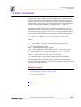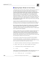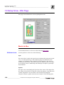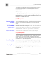
1
FOCUS GC Gas Chromatograph Setup User’s Manual Published by Technical Publications, Thermo Finnigan Italia S.p.A Strada Rivoltana 20090 Rodano-Milan Italy Printing History: Revision A printed March 2003. Xcalibur™ and FOCUS GC ™ are trademarks and/or product names of Finnigan Corporation. Microsoft® is a registered trademark of Microsoft Corporation. Technical information contained in this publication is for reference purposes only and is subject to change without notice. Every effort has been made to supply complete and accurate information; however, Thermo Finnigan Corporation assumes no responsibility and will not be liable for any errors, omissions, damage, or loss that might result from any use of this manual or the information contained therein (even if this information is properly followed and problems still arise). This publication is not part of the Agreement of Sale between Thermo Finnigan Corporation and the purchaser of a Thermo Finnigan system. In the event of any conflict between the provisions of this document and those contained in Thermo Finnigan Corporation’s Terms and Conditions, the provisions of the Terms and Conditions shall govern. Reference to System Configuration and Specifications supersede all previous information and are subject to change without notice. The GC/MS and LC/MS products of the Thermo Finnigan Division are produced under VISION 2000 accredited quality management systems. U.S.A.: Thermo Finnigan Corporation • 355 River Oaks Parkway • San Jose, CA 95134-1991 • [1] (408) 965-6000 Thermo Finnigan Technical Support • 3661 Interstate Park Road North • Riviera Beach, FL 33404 • (800) 685-9535, (561) 844-5241 • Fax (561) 8818431 Australia: Thermo Finnigan • P.O. Box 239 Rydalmere• Unit 20, Metro Centre • 38 – 46 South Street • Rydalmere, N.S.W. 2116 • [61] (02) 9898-9000 Austria: Thermo Finnigan GmbH • Wehlistrasse 27b • A-1200 Wein • [43] (01) 333 50 34-0 • [email protected] Belgium: Thermo Finnigan BVBA • Groenenbrogerlaan 84 • B-2610 Wilrijk (Antwerpen) • [32] (03) 825 0670 Canada: Thermo Finnigan Canada • 5716 Coopers Avenue, Unit 1 • Mississauga, Ontario • L4Z2E8 • [1] (905) 712-2258 France: Thermo Finnigan France SA • Parc Hightec Sud • 12 Avenue des Tropiques • Z.A. de Courtaboeuf BP141 • F-91944 Les Ulis Cédex • [33] (01) 69 18 88 10 Germany: Thermo Finnigan Analytische Systeme GmbH • Boschring 12 • D-63329 Egelsbach • [49] (06103) 408 0 Italy: Thermo Finnigan Italia S.p.A. • Strada Rivoltana • I-20090 Rodano (Milano) • [39] (02) 95059 1 Japan: Thermo Finnigan K.K. • Nishi-Shinjuku Toyokuni Bldg. 3F • 2-5-8 Hatsudai, Shibuya-ku • Tokyo 151-0061 • [81] (03) 3372-3001 Japan: Thermo Finnigan K.K. • Esaka Grand Building • 2-3-1 Esaka-cho, Suita City • Osaka 564-0063 • [81] (06) 6387-6681 Netherlands: Thermo Finnigan BV • Druivenstraat 33 • NL – 4816 KB Breda • [31] (076) 587 8722 P.R. China: Thermo Finnigan China • Suite 912-916, Ping An Mansion. • No. 28, Jin Rong Street • Xicheng District • Beijing 100032 • [86] (010) 6621 0839 Spain: Thermo Finnigan SA • Acer 30 – 32 • Edificio Sertram – Planta 2, Modulo 3 • ES-08038 Barcelona • [34] (093) 223 0918 Spain: Thermo Finnigan SA • Avenida de Valdelaparra 27 • Edificio Alcor – Planta 2a • ES-28108 Alcobendas (Madrid) • [34] (091) 657 4930 Sweden: Thermo Finnigan AB • Pyramidbacken 3 • S-141 75 Kungens Kurva (Huddinge) • [46] (08) 680 0101 United Kingdom: Thermo Finnigan Ltd. • Paradise • Hemel Hempstead • Herts HP2 4TG • [44] (01) 442 233 555 Notes: The country code is enclosed in square brackets [ ]. The city code or area code is enclosed in parenthesis ( ). For countries other than the U.S.A., when you are dialing from within the specified country, dial the 0 of the city code. For countries other than Italy, when you are dialing from outside the country, do not dial the 0 of the city code. Copyright© 2002 Thermo Finnigan, a member of the Thermo Electron family of companies. All rights reserved. Printed in Italy ____________________________________________________________________________________________ Contents FOCUS GC Configuration ....................................................................................................................6 Connection Group Box ..........................................................................................6 Options Group Box ................................................................................................6 Status Tabs ............................................................................................................................................7 General Group Box ........................................................................................................7 Run Group Box ......................................................................................................7 Emergency Conditions Group Box ........................................................................7 Button .....................................................................................................................8 Actual Values Page 8 Instrument Setup ...................................................................................................................................9 Carrier Box .............................................................................................................9 Handshake Group Box ...........................................................................................9 Valves Group Box ................................................................................................10 FOCUS Menu .....................................................................................................................................11 Flow Calculator ...................................................................................................................................12 Related Topic .......................................................................................................14 Using Flow Calculator .................................................................................................15 Column parameters group box .............................................................................15 Column outlet pressure group box .......................................................................15 Carrier gas parameters group box ........................................................................16 Using the slider bar and buttons ...........................................................................16 Related Topics .....................................................................................................17 Vapor Calculator .................................................................................................................................18 Related Topics: ....................................................................................................18 Comparing Vapor Volume to Liner Volume ...............................................................19 Using Vapor Calculator ...............................................................................................20 Inlet parameters group box ..................................................................................21 Vapor volume group box .....................................................................................21 Solvent parameters group box .............................................................................21 Liner volume group box .......................................................................................22 Setup View - Oven Page .....................................................................................................................23 Oven Temperature Program Graph ......................................................................23 Oven Temperature Program Parameters ..............................................................23 Oven Group Box ..................................................................................................24 Setting Up Oven Ramp Parameters ......................................................................... Setup View - SSL Page .......................................................................................................................25 Mode List Box .....................................................................................................25 Inlet Group Box ...................................................................................................26 Purge Group Box .................................................................................................26 Surge Group Box .................................................................................................27 Related topics: ......................................................................................................27 _________________________________FOCUS Gas Chromatograph Setup User’s Manual ___________________iii ____________________________________________________________________________________________ Setting Up Parameters for Split Mode ........................................................................ 27 Setting Up Parameters for Splitless Mode .................................................................. 27 Setting Up Parameters for Splitless with Surge Mode ................................................ 28 Setup View - Carrier Page .................................................................................................................. 29 Flow Mode list box ............................................................................................. 29 Gas Saver group box ........................................................................................... 30 Related Topics ..................................................................................................... 30 Setting Up Parameters for Constant Flow Mode ........................................................ 31 Setting Up Parameters for Constant Pressure Mode ................................................... 31 Setup View - MS Transfer Line Page ................................................................................................. 33 MS Transfer Line Box ........................................................................................ 33 Setup View - Run Table Page ............................................................................................................ 34 Time, Item, and Settings ..................................................................................... 34 Buttons ................................................................................................................ 34 Initial Values Group Box .................................................................................... 35 Related topics: ..................................................................................................... 35 Setting Up Parameters for Run Table ......................................................................... 35 Using the Add/Event Run-Time Event Dialog ........................................................... 35 Event Time group box ......................................................................................... 36 Valve Event Group Box ...................................................................................... 36 External Event Group Box .................................................................................. 36 Keypad ................................................................................................................................................ 37 Description .......................................................................................................... 37 Keypad Menus .................................................................................................... 37 Column Evaluation ............................................................................................................................. 39 How to Perform Column Evaluation .......................................................................... 39 Expected K Factor ....................................................................................................... 40 Helium Carrier Gas Theoretical K Factor ........................................................... 40 Nitrogen Carrier Gas Theoretical K Factor ......................................................... 41 Hydrogen Carrier Gas Theoretical K Factor ....................................................... 42 Leak Check ......................................................................................................................................... 43 How to Perform an Automatic Leak Check ................................................................ 43 Valves Manual Activations ................................................................................................................ 44 iv _____________________________ FOCUS Gas Chromatograph Setup User’s Manual ______________________________ Chapter 1 FOCUS GC Instrument Setup This chapter contains the instruction to operate on your FOCUS GC. FOCUS GC Configuration 6 Status Tabs 7 Instrument Setup 9 FOCUS Menu 11 Flow Calculator 12 Vapor Calculator 18 Setup View - Oven Page 23 Setup View - SSL Page 25 Setup View - Carrier Page 29 Setup View - MS Transfer Line Page 33 Setup View - Run Table Page 34 Keypad 37 Column Evaluation 39 Leak Check 43 Valves Manual Activations 44 _______________________________ FOCUS Gas Chromatograph Setup User’s Manual__________________ 1-5 FOCUS GC Instrument Setup FOCUS GC Configuration________________________________________________________________________ 1.1 FOCUS GC Configuration This dialog box is available from the Instrument Configuration window. Select the FOCUS GC and then select the configure button. The following FOCUS GC configuration window display: Connection Group Box Serial Port Select the COM port in which your FOCUS GC is connected. A COM port is a 9-pin cable connection located on the back of your computer. Options Group Box Pressure Units MS Transfer Line Temp. Control 1-6 Specify the pressure unit measurement to use in your work sessions. Pressure measurement units to select include kPa, bar, and psi. Check this box if the MS transfer line temperature control is required. ___________________________ FOCUS Gas Chromatograph Setup User’s Manual ______________________________ FOCUS GC Instrument Setup ____________________________________________________________________ _____________ Status Tabs 1.2 Status Tabs Status pages for your FOCUS GC are located on your Xcalibur RoadmapHome page. Just highlight FOCUS GC from the Roadmap Status tab scroll list and see the following pages (status, temperatures, flows, and pressures) display the current GC status. Status Page General Group Box Status Indicates if instrument is communicating to Xcalibur. Run Group Box Elapsed time Remaining time The amount of time that has elapsed since the run started. The amount of time that remains before the run finishes. Emergency Conditions Group Box Emergency shutdown Your Xcalibur software automatically checks this box if an error condition like a leaking hydrogen sensor or something is malfunctioning internally in your FOCUS GC. The software automatically shuts the FOCUS GC off. Check your FOCUS GC Maintenance and Troubleshooting Manual for possible solutions. Over temperature This box is checked only when Xcalibur software detects the temperature is _______________________________ FOCUS Gas Chromatograph Setup User’s Manual _________________________ 1-7 FOCUS GC Instrument Setup Status Tabs ___________________________________________________________________________________ over the recommended level. Shorted RTD This detected problem requires certified technical support. Contact your local TMQ Tech Support office for service. Shorted oven RTD This detected problem requires certified technical support. Contact your local TMQ Tech Support office for service. Button Keypad It allows to access the FOCUS GC keypad Actual Values Page The Actual Status page displays the actual and the setpoint values of the FOCUS GC parameters set in the Instrument Setup dialog window. 1-8 ___________________________ FOCUS Gas Chromatograph Setup User’s Manual ______________________________ FOCUS GC Instrument Setup ____________________________________________________________________ _________ Instrument Setup 1.3 Instrument Setup Allows to set: the carrier gas type to use, the signal selection (Handshake) to allows the correct cooperation between FOCUS GC and MS detector, and to configure external valves or devices. To setup FOCUS GC, select FOCUS menu the option Instrument Setup. Carrier Box Parameter Description Gas Type Select the type of carrier gas to use for the analyses (He, N2, H2). Verify that the carrier gas used has been properly connected to the GC. WARNING: Hydrogen is a potentially dangerous gas. Handshake Group Box The FOCUS GC cooperates with a MS detector during the analysis. To allow the device to run properly, you must indicate how the signal will change. _______________________________ FOCUS Gas Chromatograph Setup User’s Manual _________________________ 1-9 FOCUS GC Instrument Setup Instrument Setup_______________________________________________________________________________ Parameter Range Description Remote Start IN Pulse High to Low (default) Pulse Low to High This parameter allows another device to start the FOCUS GC. Inhibit Ready When Low (default) When High This parameters delays readiness until the GC receives a signal from another device. End of Run OUT Pulse High to Low (default) Pulse Low to High This parameter signals another device that the run has ended. Autostart On/Off Check this box to turn on auto start execution. Start of RUN OUT Pulse High to Low (default) Pulse Low to High This parameter signals another device that the run has started. GC Ready OUT When Low (default) When High This parameter signals another device that the GC is ready. Prep-Run OUT Pulse High to Low (default) Pulse Low to High This parameter signals another device that the GC is preparing for a run. Valves Group Box In this box you can configure two gas sampling valves, when present, and program two external events to be the default condition for an external device. See also Run Table Page. 1-10 Parameter Range Description Valve #1 None - Sampling Select in this box Sampling only if a gas sampling valve is present and connected to the GC. Otherwise, select none. _________________________ FOCUS Gas Chromatograph Setup User’s Manual ______________________________ FOCUS GC Instrument Setup ____________________________________________________________________ _________ Instrument Setup Valve #2 EV #1 default See Valve #1 On - Off EV #2 default See EV #1 Select the external event default condition. The external device will return to the condition specified by the external event you have programmed to be the default whenever the GC’s in Standby mode. _______________________________ FOCUS Gas Chromatograph Setup User’s Manual ________________________ 1-11 FOCUS GC Instrument Setup FOCUS Menu _________________________________________________________________________________ 1.4 FOCUS Menu The FOCUS menu is located on the Instrument Setup-menu bar Options Description Instrument Setup Allows performing instrument setup. Refer to Instrument Send Method to GC Downloads the GC portion of the current method from the Instrument Setup window to the gas chromatograph. Get Method from GC Uploads the current method from the gas chromatograph to the Instrument Setup Window. Start GC / Prep Run Allows starting the GC run. Stop GC Allows stopping the GC run. Keypad Allows accessing Keypad. Column Evaluation Allows performing a Column Evaluation. Leak Check Allows performing an Automatic Leak Check. Valves Allows Valves Manual Activation. Flow Calculator Allows determining column pressure settings and flowing rates through a capillary column. Refer to Flow Vapor Calculator 1-12 Setup. Calculator To rapidly calculate the expansion volume of several factors. Refer to Vapor Calculator _________________________ FOCUS Gas Chromatograph Setup User’s Manual ______________________________ FOCUS GC Instrument Setup ____________________________________________________________________ __________ Flow Calculator 1.5 Flow Calculator Column Flow Calculator allows you to make changes in non-DPFC pneumatics, which affect carrier gas flow and velocity. Additionally you may: • Change the column length, id (inner diameter), temperature, or inlet pressure by moving any of the “Column Parameters” slider bars will change the calculated values for flow, velocity, and hold-up time. (Changing outlet pressure or carrier gas type will also result in recalculation of the carrier flow and velocity, but they are set on different parts of the screen because they are less likely to be varied during method development than the other column parameters.) • Change the “Carrier Gas Parameters” slider bars for either flow or linear velocity* will calculate the inlet pressure needed to give that flow rate or velocity, keeping the other column parameters constant. • See the Flow, linear velocity, and hold-up time simultaneously when a column parameter changes. While all calculations are solved directly, calculating inlet pressure from velocity (at greater than zero outlet pressure) is done using an approximation technique. Pressure/Flow Calculations The rate of carrier gas flow through an open tubular column can be calculated using the well-understood relationships between pressure and flow in capillary GC. These calculations are useful in your method development and for you to determine the inlet pressure for a particular column and carrier flow or the change in flow resulting from a temperature or pressure program. The FOCUS GC performs a column evaluation where the actual column resistance is calculated. Thus, insuring and achieving accurate column flows for a specific column length, ID, and the wall coating. Split Ratio Calculations The split ratio for a capillary inlet is determined by the relationship between the split vent flow and the column flow. Chromatographers calculate split ratio in several ways and refer to this subject as: split flow/column flow, column flow/split flow, or total flow/column flow. For these calculations, split ratio is defined as Split Ratio= SR1 = (split vent flow) / (column flow) Split ratio is usually expressed as a ratio relative to one. For example, for a split vent flow of 100 ml/min and a column flow of 2 ml/min, SR1 = (split vent flow/column flow) : (column flow/column flow) = 50:1 On the pressure/flow calculator screen, the split ratio is always based on the current value for column flow. Entering a value for either split vent flow or _______________________________ FOCUS Gas Chromatograph Setup User’s Manual _______________________ 1-13 FOCUS GC Instrument Setup Flow Calculator ________________________________________________________________________________ split ratio and clicking on “Calc Flow/Ratio” calculates the other. Column Outlet Flow The Poiseuille equation gives the gas flow carrier rate through an open tubular GC column. For a given set of experimental conditions - column length and id, carrier gas type, temperature, and outlet pressure - this equation can be used to calculate the flow expected with a known inlet pressure, or the pressure setting needed to give a desired flow rate. F = outlet flow in ml/min, measured at Tref and pref(standard conditions) = [ 60 p r / 16 h L ] [ (pi - po) / po] [ po / pref] [ Tref /T ](Eq. 1) where: r = column inner radius, cm L = column length, cm pi = inlet pressure (absolute), dynes/cm po = outlet pressure (absolute), dynes/cm pref = reference pressure, typically 1 atm T = column (oven) temperature, °K Tref = reference temperature, typically 25 ° C (298 °K) h= carrier gas viscosity at column temperature, poise 60 = conversion from seconds (cgs units) to minutes Average Linear Velocity The rate at which carrier gas moves through the GC column can also be expressed in terms of its linear velocity. Because pressure on the carrier gas changes at each point along the column, the gas will expand as it flows through the column, and linear velocity will increase from the inlet to the outlet. The retention time for a component reflects the average linear velocity, which is measured by determining the elution time for an unretained peak. = average linear velocity at column temperature T, cm/sec = L / tM (Eq. 2) where: L= column length, cm tM = hold-up time, elution time for an unretained component, sec The average linear velocity is related to the outlet velocity by the compression correction factor. =uoxj where: 1-14 _________________________ FOCUS Gas Chromatograph Setup User’s Manual ______________________________ FOCUS GC Instrument Setup ____________________________________________________________________ __________ Flow Calculator j= compression correction factor (compressibility correction factor) = 3 po (pi - po ) / 2 (pi - po ) As with equation 1 for flow under a given set of experimental conditions, the average linear velocity can be calculated from the column dimensions, viscosity, and pressure. =[3r / 32 η L][ (pi - po ) /( pi - po )] Eq. 3) Linear velocity is calculated here at oven temperature, to correspond with retention time measurements. (Temperature does not appear explicitly in equation 3, but the viscosity value is a function of temperature.) Vacuum Outlet Conditions With most GC detectors, pressure at the column outlet (po) is about 1 atm. In GC/MS systems, however, the column outlet pressure is zero. This makes the flow rate at outlet conditions very high, but column flow under reference conditions can still be calculated from equation 1. (This corresponds to the flow that would be measured with a flow meter connected to the discharge of the vacuum pump, if such a measurement could be made). With po << pi , equation 1 becomes, F = [ 60 π r / 16 η L] [pi Other Pressures / pref ] [ Tref /T] There are some cases where the column outlet is neither at atmospheric pressure nor under vacuum. One example is a column with a restrictor installed at the end. This could be a length of narrow-bore tubing connected to a mass spectrometer, as discussed in the topic Vacuum Outlet Conditions or a splitter with connections to two different detectors. Related Topic • Using Flow Calculator _______________________________ FOCUS Gas Chromatograph Setup User’s Manual _______________________ 1-15 FOCUS GC Instrument Setup Flow Calculator ________________________________________________________________________________ Using Flow Calculator Use the Column Flow Calculator to determine column pressure settings and flow rates through a capillary GC column when operating with manual pneumatics. Column dimensions, temperature, inlet and outlet pressure, and carrier gas type can be varied when calculating an outlet flow rate, average linear velocity, and holdup time. Column parameters group box Each control listed in this box is affected by the choices made in the Carrier Gas Parameters group box. Length Slide the slider bar to the desired column length in meters. Inside diameter Slide the bar to the columns inside diameter in millimeters. Temperature Slide the bar to the oven temperature you want to use (ºC). Inlet pressure Slide the bar to the pressure amount to supply to the column head (k) Column outlet pressure group box Use the Radio Buttons and Slider Bars to adjust the outlet pressure. Atm Vacuum 1-16 Atmospheric pressure. Select this if your FOCUS is connected to a mass spectrometer. _________________________ FOCUS Gas Chromatograph Setup User’s Manual ______________________________ FOCUS GC Instrument Setup ____________________________________________________________________ __________ Flow Calculator Other Select this if you want to adjust column outlet pressure above or below atmospheric (0-43.5 psi) Outlet Pressure Slide the bar to the desired pressure amount the column flow will push against at the column exit Carrier gas parameters group box Gas type Flow Velocity Holdup time Select the type of gas you are using for column flow. Actual flow calculated based on items listed in Column Parameter box. This is the speed in which the flow travels to the column. Time for non-retained peak to travel through the column. Hold-up time is measured to determine the average linear velocity. Using the slider bar and buttons Slider Bars Quick tips • • • • Grab (click and hold) the slider and drag it along the length of the slider bar. Click on the arrow buttons on either end of the slider bars to increase or decrease the associated value. The amount of increase or decrease depends on the number of decimal places in the parameter, and will vary for different slider bars. Click on the area between the slider and the arrow buttons to increase or decrease the slider bar’s associated value at 10 times the rate of clicking on the arrows. Use your mouse or tab key to select a slider bar and then use the right and left arrow keys located on your PC’s keyboard to adjust the values. This method produces the same results as using the arrows. Radio Buttons Use radio buttons to select one or several choices, however, only one radio button from any group can be selected at the same time. Reset Button Click to reset all control parameters back to the factory settings. The only _______________________________ FOCUS Gas Chromatograph Setup User’s Manual _______________________ 1-17 FOCUS GC Instrument Setup Flow Calculator ________________________________________________________________________________ parameters for which default values can be changed and saved are pressure units (kPa, psi, or bar) and the controls listed in the Column Outlet Pressure group box (1 atm, vacuum, other, and outlet pressure). Done Button Press Done to exit the screen. The pressure units and outlet pressure currently selected save to disk and become the new defaults for the remaining work session. Current pressure units (kPa, psi, or bar) and outlet pressure (1 atm, vacuum, or outlet) settings save and load automatically when you open the screen again. Values for all of the other parameters return to the factory default settings. Related Topics 1-18 • Pressure/Flow Calculations • Split Ratio Calculations • Column Outlet Flow • Average Linear Velocity • Vacuum Outlet Conditions • Other Pressures _________________________ FOCUS Gas Chromatograph Setup User’s Manual ______________________________ FOCUS GC Instrument Setup ____________________________________________________________________ _________ Vapor Calculator 1.6 Vapor Calculator Calculates the vapor volume for the PTV and SSL inlets from the injection volume in proportion to the installed liner column. Assuming, if the vapor behaves like an ideal gas and only solvent vapor needs to be considered for dilute samples: vapor volume (V) for n solvent moles at temperature T and pressure p is then approximated by the ideal gas law: V = nRT / p. Absolute temperature and pressure are used for the calculations, and n is determined from the solvent volume, density, and molecular weight. Since 1 mole of an ideal gas occupies 22.4 liters at 0° C and 1 atmosphere pressure, vapor volume in microliters can be calculated from the following equation: V = [22.4 x ] [ r / MW] [(T + 273) / 273] [ patm / (pi + pa)] [Vinj] where: V = vapor volume, microliters, at inlet temperature and pressure Vinj = solvent (liquid) volume, microliters injected r= solvent (liquid) density, g/ml MW= solvent molecular weight, g/mole 22.4= liters occupied by 1 mole of ideal gas at 0 °C and 1 atm pressure T= inlet temperature, °C (absolute temperature = °K = °C + 273) pi = inlet pressure, gauge (absolute pressure = pi + pa) patm = 1 atm pressure (14.7 psi, 101 kPa, or 1.01 bar) pa= ambient pressure, usually taken as patm for this approximation Solvent boiling points, molecular weights, and densities can be found in references such as the Handbook of Chemistry and Physics (CRC Press) and the Merck Index (Merck & Co.). Related Topics: • Comparing Vapor Volume to Liner Volume • Using Vapor Calculator _______________________________ FOCUS Gas Chromatograph Setup User’s Manual _______________________ 1-19 FOCUS GC Instrument Setup Vapor Calculator _______________________________________________________________________________ Comparing Vapor Volume to Liner Volume Comparing vapor expansion volumes with liner volumes gives an estimate of the sample volume that can be injected under different conditions. In practice, mixing and diluting sample vapor with carrier gas during rapid evaporation means that the actual volume occupied by vapor may be greater than the calculated volume, and it depends on the liner design and how rapidly carrier gas is moving through the inlet. A good starting point in method development is to choose the liner, injection volume, temperature, and pressure so that the vapor volume does not exceed the liner volume. (For splitless injections, the liner volume should also be considered in choosing the purge hold time, so that the inlet will be swept at least once by carrier gas flowing onto the column.) Typical volumes for capillary inlet liners have a range of 250 to 1000 microliters. Volume for an open liner can be calculated from the length and inner diameter, but it may be reduced by internal constrictions or packing. Rate of carrier gas flow at the column outlet. Usually given as volumetric flow in ml/minute. Because the volume for a given mass flow will depend on temperature and pressure (p=nRT), the conditions under which flow is calculated or measured must be specified. See the section on “Column Outlet Flow” for details of the calculations. Velocity, at which carrier gas moves through the column at temperature T, is represented in cm/sec. Because pressure varies continuously along the column (from pi to po), linear velocity also changes at each point between inlet and outlet. The elution time for an unretained component provides a measure of the average linear velocity. This is related to outlet velocity (and flow) through the compression correction factor j. See the topic on Average Linear Velocity for details of the calculations. An unretained component's (at column temperature T) elution time is a measure of time that sample components spend in the mobile phase. Hold-up time is measured to determine the average linear velocity. F = outlet flow in ml/min, measured at Tref and pref (standard conditions) F = [ 60 p r / 16 h L ] [ (pi - po ) / po] [ po / pref] [ Tref /T ](Eq. 1) U = average linear velocity at column temperature T, cm/sec U= L / tM (Eq. 2) Under a given set of experimental conditions, the average linear velocity can be calculated from the column dimensions, viscosity, and pressure. U 1-20 = [ 3 r / 32 h L] [ (pi - po ) / ( pi - po )](Eq. 3) _________________________ FOCUS Gas Chromatograph Setup User’s Manual ______________________________ FOCUS GC Instrument Setup ____________________________________________________________________ _________ Vapor Calculator Flow can then be determined indirectly from the average linear velocity. F = [ 60 p r ] [Tref / T] [ 2( pi - po ) / 3 pref (pi - po )] (Eq. 4) The equation used to calculate inlet pressure from velocity could be quite slow under certain column conditions. At outlet pressures greater than vacuum the equation cannot be solved directly. Instead, the equation is solved by a successive approximation method. You can speed this process up by using the flow slider bar to indirectly change the velocity value. Electronic pressure control (EPC) provides an alternative to mechanical pressure control for regulating the gas flow in your FOCUS GC. Additionally, EPC provides stability and precision in flow settings, which makes it possible to use pressure/flow programming in GC methods and to document pressures along with the other parameters. Using Vapor Calculator A liquid sample injected into a heated GC inlet rapidly vaporizes and expands. Vapor Volume Calculator rapidly calculates the expansion volume using several factors (solvent, injected liquid volume, temperature, and inlet pressure). Included with this calculation is the resulting vapor expansion volume relative to the inlet liner’s inner dimensions. Because, if the volume of vapor is greater than that of the liner, the excess can expand into other areas of the inlet and result in loss of sample or contamination of the gas lines. Inlet parameters group box Injection volume Slide the bar to the volume amount to inject. _______________________________ FOCUS Gas Chromatograph Setup User’s Manual _______________________ 1-21 FOCUS GC Instrument Setup Vapor Calculator _______________________________________________________________________________ Temperature Pressure gauge Slide the bar to the temperature your method calls for. Slide the bar to the pressure amount your method calls for. Vapor volume group box Vapor Volume An injected solvent’s calculated expansion volume. Compare this to a list of the most frequently used liners and their available internal volume. If you are using a DPFC system, pressure programming can be used to help control vapor volume. With the Surge Pressure Pulse technique, pressure is briefly increased at the time of injection, and then returned to the setpoint best for column flow rate during the rest of the run. Advantages for this technique include: Optimizing conditions for sample transfer to the column Facilitating larger injection volumes Reducing sensitive components residence time inside the inlet Solvent parameters group box Type Select the solvent type you wish to use. Choosing a specific type automatically sets preferred values in all the other fields. However, you still may make adjustments. If any of your adjustments exceed the recommended allowance for the liner, then Xcalibur displays an error message. Values you see listed in Type are for the most common solvents that have densities at 20° C. Select Other to calculate expansion volumes for other solvents not listed here. Then you may enter the appropriate values for the rest of the Solvent Parameters (boiling point, molecular weight, and density.) Boiling Point 1-22 This is shown on the screen for reference, although it is not used in the calculations. Because the approximation for vapor volume does not really apply near the solvent boiling point, calculations are not done if the inlet temperature is set within 20°C of this value. Instead, a message displays, indicating that a higher temperature should be specified. Density For dense solvents with low molecular weights give the largest vapor volume per microliter injected. The effects of inlet temperature and pressure on vapor volume can also be seen from the equation - increasing temperature increases volume, while increasing pressure decreases volume. Mol. Weight Molecular weight. The average mass of a molecule of a compound compared to 1/12 the mass of carbon 12 and calculated as the atomic weights sum of the _________________________ FOCUS Gas Chromatograph Setup User’s Manual ______________________________ FOCUS GC Instrument Setup ____________________________________________________________________ _________ Vapor Calculator constituent atoms. Or simply stated, the average mass of a molecule of a compound expressed in atomic mass units (AMU). Liner volume group box Type (part no.) Select a liner type from the list box. Vapor Volume Calculator automatically displays the Liner Volume (ml) value. _______________________________ FOCUS Gas Chromatograph Setup User’s Manual _______________________ 1-23 FOCUS GC Instrument Setup Setup View - Oven Page_________________________________________________________________________ 1.7 Setup View - Oven Page This page is the method editor for setting up parameters in the GC run. Oven Temperature Program Graph Oven Temperature Program graph Graphical representations of the oven temperature program including any post run events. The axes are temperature in degrees centigrade and time in minutes. An isothermal run just gives a flat line Oven Temperature Program Parameters Ramps arrow buttons Use the up-down control to add or subtract the number of ramps to use in the oven temperature program. This is the rate in degrees Centigrade per minute the GC oven is ramped up or down from the initial temperature or the previous level’s final ramp temperature. Clicking on the Down arrow automatically adds a ramp level after the last one listed. Clicking on the Up arrow deletes the highest level or the one being displayed on the bottom Initial / Temp text box The initial temperature the oven is set at the beginning of the temperature program. For isothermal runs, this is the oven temperature for the entire run. After Preready or Prep Run this is the temperature the oven will be at. Initial / Hold Time text box The amount of time to maintain the initial temperature. 1-24 _________________________ FOCUS Gas Chromatograph Setup User’s Manual ______________________________ FOCUS GC Instrument Setup ____________________________________________________________________ ___ Setup View - Oven Page Ramp / Rate text boxes The rate of change of the temperature when increasing it from one value to the next. Described in degrees Celsius per minute (°C/min). The ramp begins at the previous step’s final temperature value and proceeds to the current step’s final temperature at the specified rate. Ramp / Temp text boxes The temperature the oven is set at for the next ramp of the temperature program. For isothermal runs, this is the oven temperature for the run. After Prep Run this is the temperature the oven will be at. Ramp / Hold Time text boxes The time to maintain the temperature specified in the Final Value control box. Oven Group Box Automatic PrepRun Check this box for the GC to automatically go to the Ready state when the initial conditions are met. If this box is not checked, you will have to press the Start key located on the FOCUS GC virtual keypad or to select the option StartGC/PrepRun in FOCUS GC menu. Max Temp text box Specify the maximum temperature for this run. The GC has a maximum temperature of 350°. The maximum allowable temperature for the column being used in the method is automatically set. PrepRun Timeout Equilibration Time (min) text box Specify how long the GC should remain in the Ready to Inject mode before returning to Stand By. If the GC Start button is not pressed within the prep run timeout period, then the GC will return to Stand By mode. This feature is a protective measure to keep the GC from being in the Ready to Inject mode too long. For example, this will prevent accumulation of contaminants on the analytical column when doing splitless injections. Specify how much time the GC should wait after the initial conditions are met before going to standby. Setting Up Oven Ramp Parameters Set oven ramp parameters 1. Open the Instrument Setup window. 2. Display the Oven page by clicking on the FOCUS panel button 3. Type in the temperature (degrees Celsius) and time (in minutes) for the initial oven parameters. 4. To add ramps to the oven temperature program, click on the down arrow of the up-down control. If you add too many ramps, click on the up arrow to delete them. _______________________________ FOCUS Gas Chromatograph Setup User’s Manual _______________________ 1-25 FOCUS GC Instrument Setup Setup View - SSL Page__________________________________________________________________________ 1.8 Setup View - SSL Page This page is the method editor for the Split/Splitless inlet. Mode List Box Use the Mode list box to select one of the following SSL modes: SSL Modes list box Use this spin box to select one of the following: Split The carrier flow is split in the injection port with the bulk going out the split vent. Use this injection type when analyzing high concentration or neat samples, or in instances where sensitivity is less important. The split vent remains open all the time. This method yields the sharpest peaks, if the split gas is properly mixed. Additionally, this technique can improve peak shape and resolution. Splitless The split vent is closed during the injection to drive most of the sample into the column. Solvent effect is required to refocus the analytes, especially more volatile components. You can achieve solvent effect by keeping the analytical column or guard column near the sample's solvent boiling point. 1-26 _________________________ FOCUS Gas Chromatograph Setup User’s Manual ______________________________ FOCUS GC Instrument Setup ____________________________________________________________________ ____ Setup View - SSL Page This technique also requires the spilt valve be opened after the injection to prevent band broadening due to solvent flooding. Splitless times of ~ 1 minute are typical. Splitless w/surge A surge is applied during the splitless time to reduce residence time of the analytes in the inlet. This will reduce band broadening and may sharpen peaks, especially for more volatile components, which are not improved by cold trapping effects on the column. Usually this technique involves an oven temperature ~ 50C° below BP of analyte. Inlet Group Box Temperature check box and text box The setpoint for the inlet's temperature. Depending on the mode of injection, it should be set at a temperature appropriate to vaporize the sample and solvent. Split Flow check box and text box Specify the total split flow coming out of the inlet. This is the total flow out of the inlet when the split valve is open. Split Ratio text box Splitless Time text box The ratio of split vent flow to the column flow. Calculate the split ratio as shown: Split Ratio = (column flow + split vent flow) / (column flow). The amount of time after the injection at which the split vent opens. Purge Group Box This group controls the septum purge for the inlet. Septum purge is used to sweep the bottom of the septum to reduce contamination from sample analytes. This prevents carryover from run to run Septum purge also prevents contamination of the inlet from septum bleed. Constant Septum Purge check box The septum purge may be turned off during a splitless injection. Checking this box will keep the septum purge valve open continuously. By leaving this box unchecked, the analyst may close this valve during the injection splitless time. Stop Purge Time text box Enter the time (in minutes) for the septum purge valve to close after beginning the injection. The Constant Septum Purge checkbox has to be unchecked for this option to be used. This is usually set to the same time as the splitless time. _______________________________ FOCUS Gas Chromatograph Setup User’s Manual _______________________ 1-27 FOCUS GC Instrument Setup Setup View - SSL Page__________________________________________________________________________ Surge Group Box Surge Pressure The pressure applied during the splitless time to produce a surge of flow in the inlet to speed transfer of the sample. It may be used, depending upon the analysis, to sharpen peaks closer to the solvent’s boiling point where cold trapping is ineffective and solvent effect is the main refocusing mechanism. Try adding 8 psi or 55.157 kPa to the inlet and observe early peaks after the solvent to see if peak tailing is reduced. Surge Duration The amount of time a pressure surge is administered after the injection. Typically, set to coincide with the splitless time. Related topics: • Setting Up Parameters for Split Mode • Setting Up Parameters for Splitless Mode • Setting Up Parameters for Splitless with Surge Mode Setting Up Parameters for Split Mode 1. Open the Instrument Setup window. 2. Click on the FOCUS GC panel button. 3. Select the SSL tab. 4. Choose Split from the Mode list box. If you would like to set a temperature for the injector, click in the temperature check box and enter a temperature value (in degrees Celsius) in the Temperature text box. 5. Enter the split ratio. Setting Up Parameters for Splitless Mode 1. Open the Instrument Setup window. 2. Click on the FOCUS GC panel button 3. Select the SSL tab. 4. Choose Splitless from the Mode spin box. 1-28 _________________________ FOCUS Gas Chromatograph Setup User’s Manual ______________________________ FOCUS GC Instrument Setup ____________________________________________________________________ ____ Setup View - SSL Page If you would like to enter a temperature for the injector, click in the temperature check box, then enter the desired temperature in the temperature text box. If you would like to enter a split flow, click in the Split Flow check box and enter a value (mL/min) in the Split Flow text box. 5. Enter a value in the Splitless time text box. If you want to use constant septum purge, click in the Constant Septum Purge check box. Otherwise, enter the time in minutes in the Stop Purge Time text box. Setting Up Parameters for Splitless with Surge Mode Click here to display the main topic for this procedure. flow rate and pressure for ramped pressure. 1. Open the Instrument Setup window. 2. Click on the FOCUS GC panel button. 3. Select the SSL tab. 4. Choose Splitless w/ surge from the Mode list box. If you would like to enter a temperature for the injector, click in the temperature check box, and enter the desired temperature in the temperature text box. If you would like to enter a split flow, click in the Split Flow check box and enter a value (mL/min) in the Split Flow text box. 5. Enter a value in the Splitless time text box. If you want to use constant septum purge, click in the Constant Septum Purge check box. Otherwise, enter the time in minutes in the Stop Purge Time text box. 6. Enter values in the Surge Pressure and Surge Duration text boxes. _______________________________ FOCUS Gas Chromatograph Setup User’s Manual _______________________ 1-29 FOCUS GC Instrument Setup Setup View - Carrier Page _______________________________________________________________________ 1.9 Setup View - Carrier Page This page is the method editor for setting the carrier gas for the FOCUS GC inlet. Carrier is gas used as the mobile phase in gas chromatography. The carrier gas carries the analyte mixture through the GC column, where it is separated into its individual components. The carrier gas flows through the GC column at a specific rate, measured either as a linear velocity (cm/sec) or as a flow rate (mL/min). Common carrier gases are helium, hydrogen, and nitrogen. Hydrogen offers the best chromatographic properties (optimum resolution at the highest flow rates). However, because hydrogen is flammable, helium is often used as an alternative for a carrier gas. Flow Mode list box The controls you see on this page are dependent on the Flow Mode selection. Please select one of the following modes and jump to that topic for detailed information. Modes Two flow modes are available and affect the controls listed in the Ramps group box: Constant Flow — controls in the Ramp group box display Flow (mL/min). Enter a column flow for the analytical column. When using an oven temperature program, run the GC to automatically increase the pressure constant flow on the column. This compensates a gas's increased viscosity due to an increase in temperature. In this mode, the inlet pressure is varied during an analytical run as needed to maintain the column flow at a specified setpoint. This means that when a column is heated and its restriction to flow 1-30 _________________________ FOCUS Gas Chromatograph Setup User’s Manual ______________________________ FOCUS GC Instrument Setup ____________________________________________________________________ __ Setup View - Carrier Page increases the inlet pressure is increased. Constant Pressure — controls in the Ramp group box display Pressure. Enter inlet pressure for the analytical run. In this mode, a specified pressure is applied to the column and remains unchanged throughout the analysis. Flow Program graph A graphical representation of a flow program for the carrier gas. It is a flat line if a constant flow program is selected. The axes represent time for the xaxis and flow in mL/min for the y-axis. Pressure Program graph The graph represents a pressure program for the carrier gas. It is a flat line if a constant pressure program is selected. The axes represent time for the xaxis and either flow in mL/min or pressure in kPa for the y-axis. Flow text box A flow for the analytical column. For an oven temperature programmed run the GC automatically increases pressure to keep a constant flow on the column compensating for increased viscosity of gas due to increase in temperature. Pressure text box Vacuum Compensation check box Enter the inlet pressure for the analytical run in this text box. Check this box to compensate for a vacuum at the end of the analytical column. This is usually the case where the detector is a mass spectrometer. When the box is not checked calculations are made for a normal GC detector, which is usually at atmospheric or slightly higher pressure. Gas Saver group box Gas Saver check box and group box This group box contains gas saver controls, which reduce carrier gas consumption, especially when a large split flow is used. The gas saver options are set to come on at some point well after the injection to conserve gas. Checking the box will activate the other two features of gas saver. Gas Saver Flow text box The desired flow after the injection or in standby. Gas saver flow displays the carrier gas in milliseconds and minutes until the end of the run. Gas Saver Time text box The time after the injection when gas saver flow will be activated. Related Topics • Setting Up Parameters for Constant Flow Mode • Setting Up Parameters for Constant Pressure Mode _______________________________ FOCUS Gas Chromatograph Setup User’s Manual _______________________ 1-31 FOCUS GC Instrument Setup Setup View - Carrier Page _______________________________________________________________________ Setting Up Parameters for Constant Flow Mode 1. Use the following procedure to set up parameters for the constant flow option. 2. Open the Instrument Setup window. 3. Select the Carrier tab. 4. Check the On box in the Flow group box to turn on the flow. 5. Type in a value for the flow for the analytical column. 6. Check the Vacuum Compensation box to compensate for a vacuum at the end of the analytical column. 7. When the box is not checked calculations are made for a normal GC detector, which is usually at atmospheric or slightly higher pressure. Check the Gas Saver box to activate gas saver controls. Checking the box will activate the other two features of gas saver: Gas Saver Flow (mL/min): The desired flow after the injection or in standby. Gas saver flow displays the carrier gas in milliseconds and minutes until the end of the run. Gas Saver Time (minutes): The time after the injection when gas saver flow will be activated. Setting Up Parameters for Constant Pressure Mode 1. Open the Instrument Setup window: 2. Select the Carrier tab. 3. Check the pressure box to enable flow to the inlet. When this box is not checked gas flow goes to the inlet and through any installed column. If the oven is taken to a high temperature, the column may be damaged as well as any detectors or components attached to it. 4. Enter a value for the pressure for the analytical column. 5. Check the Vacuum Compensation box to compensate for a vacuum at the end of the analytical column. 6. When the box is not checked calculations are made for a normal GC detector, which is usually at atmospheric or slightly higher pressure. 7. Check the Gas Saver box to activate gas saver controls. Checking the box will activate the other two features of gas saver: 1-32 _________________________ FOCUS Gas Chromatograph Setup User’s Manual ______________________________ FOCUS GC Instrument Setup ____________________________________________________________________ __ Setup View - Carrier Page Gas Saver Flow (mL/min): The desired flow after the injection or in standby. Gas saver flow displays the carrier gas in milliseconds and minutes until the end of the run. Gas Saver Time (minutes): The time after the injection when gas saver flow will be activated in the Instrument Setup window. _______________________________ FOCUS Gas Chromatograph Setup User’s Manual _______________________ 1-33 FOCUS GC Instrument Setup Setup View - MS Transfer Line Page _______________________________________________________________ 1.10 Setup View - MS Transfer Line Page Use this tab to control the temperature of the MS transfer line. MS Transfer Line Box MS Transfer Line °C 1-34 Check this box when the MS transfer line temperature control is required and set the desired temperature setpoint. _________________________ FOCUS Gas Chromatograph Setup User’s Manual ______________________________ FOCUS GC Instrument Setup ____________________________________________________________________ Setup View - Run Table Page 1.11 Setup View - Run Table Page This page is the method editor to program events to happen before or during a run. For example, a valve could open two minutes into a run. Listed in the run table page are settings entered prior to the run in the Run Time Event dialog. Time, item, and settings display in this run table. Controls listed in the Initial Values group box are for switching external devices On/Off. Time, Item, and Settings Time It displays which Event Time (Prep run or Run Time) was selected in the Run Time Event dialog. Item It displays which event (Detector, Valve, or External) was configured in the Run Time Event dialog. Setting Displays the Detector Events settings or On/Off states for Valve and External Events. Buttons Click to view the Add/Event Run-Time Event dialog box. Run items you select from this dialog are added to the time, item, and setting table. Click to edit a selected run item listed in the Time, Item, and Setting table. Select an item listed in the time, item, and setting table. Click this button to remove the selected run item from the run table. _______________________________ FOCUS Gas Chromatograph Setup User’s Manual _______________________ 1-35 FOCUS GC Instrument Setup Setup View - Run Table Page_____________________________________________________________________ Initial Values Group Box External Event Located on the back of your FOCUS GC is a port with eight contacts that switches external devices On/Off. During a specific run times you can use these controls to set the status of these external switches prior to the run. Factory defaults for the beginning of each run is off (not checked). Related topics: • Setting Up Parameters for Run Table • Using the Add/Event Run-Time Event Dialog Setting Up Parameters for Run Table 1. Select a control from the Event Time Group Box. When do you want to start the run at Prep Run or at Run Time? 2. Select a Detector Event, Valve Event, or External Event. 3. Select the controls available under the event type you selected. 4. Click Ok. Using the Add/Event Run-Time Event Dialog 1-36 _________________________ FOCUS Gas Chromatograph Setup User’s Manual ______________________________ FOCUS GC Instrument Setup ____________________________________________________________________ Setup View - Run Table Page Event Time group box Select one of the following two options Prep Run This option makes the selected (Detector, Valve, or External) happen before the run begins. Run Time This option makes the selected (Detector, Valve, or External) happen at the time specified during the run. Valve Event Group Box If you have either a valve oven or sample valves then click the valve event button to activate valve events: Valve number Valve type Setting Select from 1 to 8 for each external event to turn on from the Run Table page. If you use all 8 then none are available for other events. Select one: Sampling. Sampling is a valve used to inject a sample volume into the carrier stream. Select Load or Inject for the sample valve settings. Whichever valve type you select determines the available setting selections in this box. External Event Group Box External events are external valves, switches, and options. Click the external event button to activate external events: External number Setting Select which of the eight (8) external events you wish to program. There are 8 available open collector outputs on the GC rear panel, which can be configured to switch external valves, switches, and other options. Select On or Off to set the external event at the specified programmed run time. _______________________________ FOCUS Gas Chromatograph Setup User’s Manual _______________________ 1-37 FOCUS GC Instrument Setup Keypad ______________________________________________________________________________________ 1.12 Keypad This virtual FOCUS GC keypad operates just like you were using it from the FOCUS GC front panel. Move your cursor across any region located in this illustration. Your cursor becomes a hand when a region has related popup topic. Use these topics to learn how the FOCUS GC keypad is functionally organized Description Display Panel The display panel displays the settings currently in use. Listed top to bottom on the display panel is typically a menu title bar, parameters, scroll indicators, and a cursor indicating your current position. Use the data-entry keys to navigate up or down the menu and to enter values. GC Status LEDs This region contains light emitting diodes, which indicate the FOCUS GC operating status. Observe the GC status periodically to determine what stage the GC is in during the run. Action Keys Use these keys to start or interrupt activities, to display the instrument status and to open menus. Listed left to right are Start, Stop, Status, Home, Dec/Inc and Enter. Data Entry Keys Use these keys to enter information into a displayed menu: Listed left to right: On/Yes, Clear, Off/No, Enter, (press to move up or down in menu), and the numerical keypad. Keypad Menus File Menu This menu permits to access the following: 1-38 _________________________ FOCUS Gas Chromatograph Setup User’s Manual ______________________________ FOCUS GC Instrument Setup ____________________________________________________________________ _________________ Keypad Get Method from GC This function allows to transfer method data from GC to data system. Send Method to GC This function allows to transfer method data from data system to GC. Close This function allows to close FOCUS keypad. _______________________________ FOCUS Gas Chromatograph Setup User’s Manual _______________________ 1-39 FOCUS GC Instrument Setup Column Evaluation _____________________________________________________________________________ 1.13 Column Evaluation The column flow control with the FOCUS GC is indirect. This means that the GC regulates pressure to control the flow of gas through the column. To do this, the GC relies on a column constant. The column constant is a measure of the columns pneumatic resistance. Use the FOCUS GC’s column evaluation feature to automatically calculate the column constant. How to Perform Column Evaluation The GC must not be performing a run and must be isothermally stable before you can perform a column evaluation. 1. In the Instrument Setup window, select the FOCUS Pull-up menu then the option Column Evaluation. The following tag appears. 2. To start Column Evaluation press . You can visualize the actual values of Oven temperature, Pressure and Column flow. Note: To exit column evaluation menu without performing column evaluation, press . 3. The GC automatically performs column evaluation. Note: To abort column evaluation press 4. After e few minutes a response message appears. Compare the response with the K Factor values, reported in paragraph Expected K Factor, according to the carrier gas used. 5. If the value obtained does not agree with the one reported on the k Factor Tables, this means that the leaks have not repaired. 1-40 _________________________ FOCUS Gas Chromatograph Setup User’s Manual ______________________________ FOCUS GC Instrument Setup ____________________________________________________________________ ________ Column Evaluation Expected K Factor The following tables indicate the expected K factors for columns of ideal dimensions when using helium, hydrogen, or nitrogen as a carrier gas. Use this information when interpreting results from a Column Evaluation. Refer to: • Helium Carrier Gas Theoretical K Factor • Nitrogen Carrier Gas Theoretical K Factor • Hydrogen Carrier Gas Theoretical K Factor Helium Carrier Gas Theoretical K Factor _______________________________ FOCUS Gas Chromatograph Setup User’s Manual _______________________ 1-41 FOCUS GC Instrument Setup Column Evaluation _____________________________________________________________________________ Nitrogen Carrier Gas Theoretical K Factor 1-42 _________________________ FOCUS Gas Chromatograph Setup User’s Manual ______________________________ FOCUS GC Instrument Setup ____________________________________________________________________ ________ Column Evaluation Hydrogen Carrier Gas Theoretical K Factor _______________________________ FOCUS Gas Chromatograph Setup User’s Manual _______________________ 1-43 FOCUS GC Instrument Setup Leak Check ___________________________________________________________________________________ 1.14 Leak Check When you perform an automatic leak check, the GC measures the column flow with a true mass flow sensor and compares it to a calculated flow value obtained from the original column constant to see if the numbers match. The instrument detects a gas leak if there is a significant difference between the two values. How to Perform an Automatic Leak Check To start the leak check operate as follows: 1. In the Instrument Setup window, select the FOCUS Pull-up menu then the option Leak Check. 2. To start leak check press . You can visualize the actual values of Oven temperature, Pressure and Column flow. Note: To exit leak check menu without performing leak check, press . 3. The system is automatically pressurized with carrier gas and sealed to perform leak check. Note: To abort leak check press 4. At the end of the leak check, if the system is free of leaks the Leak Check Passed message will be visualized. 5. .If leaks are found, an error message will be displayed. In this case, eliminate leaks and repeat the leak check procedure. Note that only a previous Column Evaluation, performed in a condition of true tightness, can ensure the validity of the subsequent Automatic Leak Check responses. 1-44 _________________________ FOCUS Gas Chromatograph Setup User’s Manual ______________________________ FOCUS GC Instrument Setup ____________________________________________________________________ __ Valves Manual Activations 1.15 Valves Manual Activations The following dialog box appears where you can manually activate the inlet valves, the sampling valve and the Event Valve #1 To display: Select the Control Panel option in the FOCUS Pull-up menu. Inlet SSL Valves Valve Vents Check in the box to open or close the Inlet valve of interest before or during a run. Set the Load or Inject position of the sampling valve (when present): _______________________________ FOCUS Gas Chromatograph Setup User’s Manual _______________________ 1-45