1
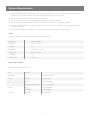
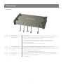
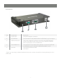
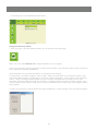
Installation Guide
GCN1000 PCPortal
GCN1000
PART NO. M0566
Table of Contents
Package Contents
4
Conventions
System Requirements
5
The Java Client
35
Java Applet Tool Bar
36
Video Parameters
Video
Keypad
Operating systems
Mouse Synchronization
38
Components
6
Message Board
Computer Preliminary Setup
8
Administrator Reset
40
GCN1000 Preliminary Setup
9
Connecting from the internet
41
GCN1000 Initial Configuration
11
Troubleshooting
43
Hardware
Setup
Table of
Contents
13
General Operation
Normal Logon
14
Java Applet
Utility Icons
15
Windows Client
44
Administration Icons
16
Additional Mouse Synchronization Procedures
45
Network
17
Windows 2000
Access ports
IP Address
Windows XP / Vista / Server / Server 2003
18
Optional Cable
DNS server
IP Change Notification
Security
19
Overview
Filtering
User Station Filtering: IP Address
20
User Station Filtering: MAC Address
User Manager
21
Customization
22
Firmware
23
Windows Client
25
Operation
27
Windows Client Control PNEL
Hotkey setup
29
Video ADJUSTMENT
30
Message Board
31
Virtual Media
33
3
46
Package Contents
The GCN1000 package Contains:
• 1 GCN1000
• 1 USB Custom KVM Cable Set
• 1 Ethernet cable (6ft)
• 1 Custom USB Console Cable Set
• 1Virtual Media USB Cable (mini B to A)
• 1 User Manual
Check to make sure that all the components are present and that nothing was damaged in
shipping. If you encounter a problem, contact your dealer.
Caution
Read this manual thoroughly and follow the installation and operation procedures carefully to prevent
any damage to the unit, and/or any of the devices connected to it.
Conventions :
This manual uses the following conventions:
Monospaced Indicates text that you should key in.
[ ] Indicates keys you should press. For example, [Enter] means to press the Enter key. If keys need to be
chorded, they appear together in the same bracket with a plus sign between them: [Ctrl+Alt].
1. Numbered lists represent procedures with sequential steps.
• Bullet lists provide information, but do not involve sequential steps.
−> Indicates selecting the option (on a menu or dialog box, for example), that comes next. For
example, Start −> Run means to open the Start menu, and then select Run.
Indicates critical information.
NOTE: Because of the uniqueness of the GCN1000 and its operation: at any given time either computer
can be considered the local or the remote computer. To avoid confusion the following convention is used:
Local computer: The computer the GCN1000 is physically attached to Remote computer
The computer that is accessing the GCN1000 from the network or internet.
4
System Requirements
• For best results, we recommend that the computers used to access, the GCN1000 control unit have
at least a P III 1 GHz processor, with the screen resolution set to 1024 x 768.
• Browsers must support 128-bit SSL data encryption.
• We recommend that the internet connection speed be at least 128 kbps.
• For the browser-based Windows Client, you must have DirectX 7.0 or higher installed.
• For the browser-based Java Applet, you must have Sun’s Java Runtime Environment Version 6
Update 3 or higher.
• Your router and ISP must support Port Forwarding to allow access from the internet.
Video
The unit supports the following resolutions and refresh rates.
Resolution
Refresh Rates
640x480
60, 72, 75, 85
720x400
70
800x600
56, 60, 72, 75, 85
1024x768
60, 70, 75, 85
1152x864
75
1280x1024
60, 75
Operating Systems
Supported operating systems:
OS
Version
Windows
Linux
UNIX
Novell
2000 and higher
RedHat
9 and higher
SuSE
10 and higher
Mandriva (Mandrake)
2007 and higher
AIX
4.3 and higher
FreeBSD
6 and higher
Netware
6 and higher
5
Components
Front View
1
2
3
4
5
No.
Component
Description
1
Reset Switch
System Reset: Pressing and holding this switch in for more that
three seconds performs a system reset.
Restore Factory Default Settings: Power off the GCN1000, then
press and hold the reset switch for at least 3 seconds while
reconnecting power.
Note: This will not reset users or passwords
2
10/100 Mbps LED
The LED lights ORANGE to indicate a 10 Mbps connection, and
GREEN to indicate a 100 Mbps connection.
3
Link LED
Flashes GREEN to indicate that a
Client program is accessing the device.
4
Power LED
Lights ORANGE when the GCN1000 is powered and ready to operate.
5
LAN Port
The network’s Ethernet cable
connection
6
PCI Interface
4
1
3
2
No.
Component
Description
1
Power Jack
The power adapter connection.
2
PC/KVM Port
The connection for the cable that links the GCN1000 to your computer.
3
USB Console Port
This is the connection for the local console cable (USB keyboard,
monitor, and USB mouse). Each port is color coded and marked
with an appropriate icon for identification. *
4
Virtual Media Port
The connection for the virtual media cable that connects the GCN1000
to a USB port on your computer. It allows file transfers to occur
5
LAN Port
The network’s Ethernet cable
connection
* Note: if you are using a wireless keyboard/mouse set, connect the receiver to the Keyboard port of the
KVM cable
7
Computer Preliminary setup
Find your computer’s IP address and default Gateway
1. Go to Start −> RUN
3. Enter CMD in the box
4. [OK] or [Enter]
A command line window opens
5. Type ipconfig
Package Contents
6. [Enter]
Look for the heading that says Ethernet adapter Local Area Connection:
7. Write down the IP Address and Default Gateway.
If the first three groups of numbers of your IP Address happens to be 192.168.0.
Proceed to Hardware set up
IP Address ....................................................................................................................................
Default Gateway ...........................................................................................................................
Exit the command line by clicking on the “X” on the top right corner of the Command line
window
8
GCN1000 preliminary setup
Connect the GCN1000 and your computer to your network using the following diagram. This is a preliminary set up so no other connections are needed.
What Is RAID?
Most home networks use automatic IP Addressing, and the GCN1000 is provided with a default fixed IP
address of 192.168.0.60: so to log in for the first time, you must have your computer and the GCN1000
on the same network.
Be sure to write down your existing settings prior to changing anything so you can return to them after the
initial set up
The following instructions will explain how to put your computer and GCN1000 on the same network, the
first set of instructions cover Windows XP and 2000, the second set explains Vista.
Windows XP and 2000
1. Go to control panel look for the Network
Connections icon
2. Double click on the icon
3. Right click on Local Area Connection
(or Wireless network connection)
4. Select Properties
5. Under the General tab highlight Internet
Protocol TCP/IP
6. Click on properties
7. Click on the Radio button “Use the following
IP address” In the top block labeled “IP
Address”
Enter: 192.168.0.65
In the center block labeled “Subnet Mask”
Enter: 255.255.255.0
Click on OK – your computer will take a few
moments to change its IP address
9
Windows Vista
1. Go to control panel
2. Select “Network and Sharing Center”
3. Select “Manage network connections”
4. Select “Local area Connection” right click select “Properties”
5. Highlight “Internet Protocol Version 4 (TCP/IPv4)
6. Select [Properties]
7. Select “Use the following IP address” In the top block labeled IP address type 192.168.0.65
Enter 255.255.255.0 for the Subnet mask Leave the default Gateway blank
8. Click [OK] – your computer will take a few moments to change its IP address
10
GCN1000 Initial configuration
1. Open your web browser. You will get a “Page cannot be displayed” error message, this is normal.
2. Type http:// 192.168.0.60 in address bar of your web browser, then [ Enter ]
3. When the certificate windows pop up, accept them.
4. When the below screen appears, log into the GCN1000:
User name: administrator (lowercase)
Password: password (lowercase).
5. After logging in, click on the Network icon along the top of the Window. This is where the GNS1000’s
network configuration settings and information are located.
11
6. Select Set IP address manually (A static IP Address is preferred)
The actual address you use is dependent on your network’s address range:
The following is an example: In the preliminary set up, the IP Address noted is 192.168.1.16, so the
IP Address you would enter would be 192.168.1.60
IP Address assigned ………………………….
6. Select Obtain DNS server address automatically,
7. For now leave the rest of the settings at their default values (they will be covered latter)
8. Click on Apply then Logout, The GCN1000 will reset. (It is important to log out so the GCN1000
will close the connection)
NOTE:
Change your computer’s IP address and Default Gateway back to the original settings as
noted in the preliminary Steps (if both are obtained automatically, click on the radio button
to restore your settings). Reconnect the computer to your network; connect the GCN1000
into your system as described in the following section:
12
Hardware Setup
Ensure that power has been removed from all devices in the installation.
You must unplug the power cords of any computers that support Keyboard Power On function.
Installation
To install the GCN1000, refer to the installation diagram:
1. Use the Console cable provided to connect the GCN1000’s Console port, to the
local keyboard, monitor and mouse, they are color coded for identification.
2. Use the KVM cable provided to connect the GCN1000’s PC/KVM port, to the video
and a USB port on the computer.
3. Connect your network cable between the GCN1000’s LAN port and your router.
4. Connect your computer to the network.
Note: Both the GCN1000 and your computer must be connected to your router. If you are using a wireless
network , switch to a wired connection to set up the GCN1000, once you know everything is working
you can switch back to wireless
Note: The GCN1000 to router connection must be wired.
5. Connect the mini B to A -USB connector between GCN1000 Virtual Media port and a USB port on
your computer.
6. Connect the power adapter cable to the GCN1000’s power jack
Installation Diagram:
13
Normal Logon
To operate the GCN1000 from an Internet browser, begin by logging in: Open your browser and specify the
IP address (assigned in the preliminary set up) of the GCN1000 in the browser’s Address bar.
1. A Security Alert dialog box, similar to the one below, appears.
Accept the certificate. If a second certificate appears, accept it as well.
The GCN1000 login page appears:
Provide a valid Username and Password
Default:
User name : administrator
Password : password
Click on Login
14
The GCN1000 Main Screen appears:
The Main Screen consists of:
Utility icons arranged vertically down the left side Administration icons arranged across the top;
Utility icons
Icon
Purpose
Apply: Saves the changes you make in the administration
dialog boxes, but does not implement the changes, which go into
effect when you enable Reset on exit (see Customization) and log out.
Windows Client: Allows users with the proper permission (see User Manager) to connect to the GCN1000 using Windows software, to remotely
control the server.
Java Applet: For platform independence, the Java applet allows users
with the proper permission (see User Manager ) and Java installed
on the remote computer, to connect to the GCN1000 and
remotely control the sever.
Log: All the events that take place on the GCN1000 are recorded in a
log file. If you have the proper permission clicking on this Icon displays
the contents of the log file
Note: See the next page for an explanation of the Log utility.
Logout: Click this icon to log out and end your session
Note: It is important to end your session, so the CN1000 can
terminate the session. If you get a “System in use” error message
its because the session ended with out Logging out, Logon with the
other Client.
15
The Log File Screen
The GCN1000 logs events that occur regarding the unit.
The file is an event database that records the last 512 events overwriting the oldest events on a continuing
basis.
To clear the log file, click on the Clear Log icon at the lower right of the page.
To view the contents of the log file, click the Log icon at the lower left of the page.
Administration Icons
The icons arranged horizontally across the top of the page are linked to the administration utilities,
which are used to configure the GCN1000. Your ability to make configuration changes depends on the
permissions associated with your login information. This chapter discusses each of them in turn.
Once you login, the General panel displays on the browser window. It is the first of the Administration
pages, and provides information about the GCN1000’s status:
16
An explanation of each of the fields is given in the table below:
Field
Explanation
Device Name:
To make it easier to manage installations that have more than one
GCN1000, each one can be given a name. To assign a name
for the GCN1000, type in one of your choosing (16 characters max.).
MAC Address:
Displays the GCN1000’s MAC Address.
Firmware Version:
Indicates the GCN1000’s current firmware version level.
Network
The Network dialog is used to specify the GCN1000’s network environment.
Access Ports
If a firewall is being used, the Administrator can specify (in the Firewall’s set up) the port numbers that the
firewall will allow. Users must specify the port number as part of the IP address when they connect to the
GCN1000. If an invalid port number (or no port number) is specified, the GCN1000 will not be found. I.E.
192.168.0.60 / 9000 (for the Windows client) and 192.168.0.60/9002 for the Java client.
Explanations of the fields are given in the table below:
Field
Explanation
Program
This is the port number that must be specified when connecting
from the Administrator and Windows Client. Valid entries are
between 1024 -60,000
Java
This is the port number used for Java connections. Valid entries are
between 1 - 65535
17
Note:
1. If there is no firewall (on an Intranet, for example), it does not matter what these numbers are set to,
since they have no effect.
2. The access ports cannot have the same value. You must set a different value for each one.
IP Address
The GCN1000 can have its IP address assigned dynamically at boot-up (DHCP), or it can be given a fixed
IP address.
Recommendation:
If you wish to access the GCN1000 from the internet, assign a static IP address because you will need to
configure your router to forward the port to the GCN1000 and an IP address is the most reliable way to
connect..
To specify a fixed IP address, select the “Set IP address manually” radio button and fill in the IP address
you wrote down in the preliminary steps (it should still be there).
The subnet mask is 255.255.255.0
The Default Gate way is the IPAddress of your router
DNS Server
The GCN1000 can have its DNS server address assigned automatically, or a fixed address can be
specified.
• For automatic address assignment, select “Obtain DNS server address automatically” (Recommended)
• To specify a fixed address, select “Use the following DNS
IP Change Notification
If you elect to use automatic IP Addressing, you can have the GCN1000 send an e-mail notification
whenever its DHCP assigned IP address changes.
• To enable e-mail notification, select the Enable check box, fill in the domain name or IP address of your
SMTP server, and specify the From: and To: e-mail addresses.
• If your SMTP server requires authentication, select the My server requires authentication check box and
fill in the Account Name and Password fields with a valid user account name and password.
• After filling in all the appropriate fields, click the Test button to test the operability of the e-mail
notification. An e-mail should be sent to the e-mail address specified in the To: field
Note: This will only notify you if the GCN1000 changes its address on your local network, it will not notify
you if your external address changes.
18
Security
The Security page is used to control access to the GCN1000.
Software Installation
Overview
•
IP and MAC Filters control access to the GCN1000 based on the IP and/or MAC addresses of the
computers attempting to access the system. If any filters have been configured, they appear in the
IP Filter and/or MAC Filter list boxes.
•
The Login string lets the Administrator specify a string that users must include along with the
GCN1000’s IP address when they access the GCN1000 with the Java Applet. For example, if the
IP address were 192.168.0.126, and the string was abcdefg, the users would key in the following:
192.168.0.126/abcdefg
Users must include a forward slash and the string along with the IP address when they log in. For
security purposes, we recommend that you change this string from time to time.
Filtering
To enable IP and/or MAC filtering, a check mark in the IP Filter Enable and/or MAC Filter Enable
checkbox enables the filter. There are a maximum of 100 filters allowed for each option.
•
If the include button is checked, all the addresses within the filter range are allowed access to the
GCN1000; all other addresses are denied access.
•
If the exclude button is checked, all the addresses within the filter range are denied access to the
GCN1000; all other addresses are
allowed access.
19
User Station Filtering – IP addresses:
To add an IP address filter:
1. Click Add. A dialog box similar to the one below appears:
2. Specify the filter address in the dialog box, and then click OK. A second dialog box,
similar to the one below, appears:
Windows XP Existing Installation
3. To filter a single IP address, key in the same address as the start IP Address. To filter a continuous range
of addresses, key in the end number of the range.
4. After filling in the address, click OK.
5. Repeat these steps for any additional IP addresses you want to filter.
To delete a filter, select it and click Remove.
To modify a filter, select it and click Edit. The Edit dialog box is similar to the Add dialog box. When it comes
up, simply delete the old address and replace it with the new one.
User Station Filtering –MAC addresses:
To add a MAC address filter Click Add. A dialog box similar to the one below appears:
1. Specify the MAC address in the dialog box, then click OK.
2. Repeat these steps for any additional MAC addresses you want to filter.
To delete a filter, select it and click Remove.
To modify a filter, select it and click Edit. When it dialogue box comes up, simply delete the old information
and replace it with the new one.
20
User Manager
The User Management page is used to create and manage user profiles. Up to 8 user profiles can be
established. To add a user profile, fill in the information asked for in the User Info panel and click Add.
The user’s name appears in the User List panel.
To delete a user profile, select it from the names displayed in the User List panel, and click Remove. The
user’s name is removed from the User List panel.
To modify a user profile, first select it from the list in the upper panel; then change the information that
appears in the User Info dialog box. The Reset button clears all the information shown in the User Info
fields. When you have made all your changes, click Update.
Note: For security, purposes change the default user name and password
Note:
The user’s password is not displayed – the Password and Confirm fields are blank. If you do not want
to change the user’s password, simply leave the two fields blank (not recommended). If you do want
to change the user’s password, key the new password in the Password field, then key it in again in the
Confirm field.
21
An explanation of the profile items is given in the table below:
Item
Explanation
User name
A minimum of 6 and a maximum of 16 characters are allowed.
Password
A minimum of 8 and a maximum of 16 characters are allowed.
Confirm Password
To be sure, there is no mistake in the password, you are asked to re-enter
it. The two entries must match.
Description
Additional information about the user that you may wish to include.
Permissions
Federal
A check mark grants permission, no check mark denies permission to the
profile being created or modified.
Configure: Administrator privileges, which allows the user to set up and
Communications
Commission
modify
the GCN1000’s (FCC)
operatingStatement
environment. / CE Statement
Windows Client: allows access the GCN1000 via the Windows Client
software.
Java Operation: Java Operation access the GCN1000 via the Java
Applet software.
Virtual Device: Enables Virtual Media
Log: allows viewing the contents of the log file.
View Only: Limits a user to viewing the video display of the remote connection.
Note: If a user is denied a permission, that permission is not visible on the Utility tool bar when that user
logs on
Customization
This configuration page allows the Administrator to set Timeout, Login failure, and Working mode
parameters.
22
An explanation of the Customization parameters is given in the table below:
Parameter
Explanation
Time out Control
If the GCN1000 does not receive any input from a computer that is
accessing it with either client within the time specified, the connection
terminates.
Login failure
Login failures allowed: Sets the number of consecutive failed login attempts
that are permitted from a remote computer.
Login failure timeout: Sets the amount of time a remote computer must wait
before attempting to login again after it has exceeded the number of allowed
failures.
Working Mode
Enable stealth mode: With stealth mode enabled, the GCN1000
will not reply to a ping request.
Reset on exit
A check here causes the GCN1000 to reset itself and implement all the new
changes when you log out. A wait of approximately 30 to 60 seconds is
necessary before logging in following the reset.
Firmware
As new versions of the GCN1000 firmware become available, they can be downloaded from our website.
Check the website regularly to find the latest information and packages.
To upgrade the firmware, do the following:
1. After downloading the new firmware file to your computer, open your browser; log in to the GCN1000;
and click the Firmware icon to bring up the Firmware File dialog box:
2. Click Browse; navigate to the directory that the new firmware file is in and select the file.
3. Click Upload.
4. After the upload completes, click the Apply icon at the left of the web page.
5. Enable the Reset on exit checkbox on the Customization page.
6. Click the Apply icon at the left of the web page, again.
7. Click the Logout icon at the upper right of the web page to exit and reset the GCN1000.
23
Using the GCN1000
This completes the GCN1000 configuration. The following chapters and steps explain how to use the unit.
We start by accessing the unit through your local network to verify the settings are correct and operate the
way you want them to. Once the setup is confirmed on your local network the finial step will be to connect
through the internet.
Required equipment
A networked computer, either on your network or on the internet, that meets the following minimum
requirements (you cannot use the computer that is directly connected to the GCN1000)
•
P III 1 GHz processor,
•
A screen resolution set to 1024 x 768.
•
A browsers supporting 128-bit SSL data encryption (all current browsers support 128-bit SSL data
encryption)
•
We recommend that the internet connection speed be at least 128 kbps.
•
For the browser-based Windows Client, you must have DirectX 7.0 or higher installed.
•
For the browser-based Java Applet, you must have Sun’s Java Runtime Environment Version 6 Update
3 or higher
Connecting from your local network
1. Ensure the “remote” computer is connected to your network
2. Ensure the GCN1000 is connected to your local network
3. Start the browser of your choice on the remote computer
4. Type in the IPAddress you wrote down in step 6 of GCN1000 Initial configuration for example
http://192.168.1.60 hit the enter key
5. You will be taken to the GCN1000 Logon screen
6. Enter your user name and password in the spaces provided and click on Logon
24
7. This brings you to the GCN1000 main screen
Contact
Using The Windows Client
1. After you log in, click the Windows Client icon on the left of the web page.
Note: You must have DirectX 7.0 or higher installed on you computer.
Note: If you are using Internet Explorer 6 or above a box similar to the one below opens when connection
to the GCN1000 has been established
Some browsers may not allow the client to run directly in their window
in those cases, you will be asked to “Save to disk”. Allow it to download to a convenient location, then,
with the browser still open, double click on the down loaded application , a box similar to the one below
opens. There is nothing actually installed on your computer, the application is merely run from your
computer (instead of directly through the browser). In keeping with the security provisions above, if you
use the “Save to disk” method, each time you use the Windows client a fresh copy of the program will be
down loaded.
2. When a connection to the GCN1000 has been established, a screen similar to the one below appears:
25
Explanations of the selection boxes are given in the following table.
Full Screen Mode
Enabled
Disabled
If Full Screen Mode is enabled, the remote display fills the entire
screen of your local monitor.
If Full Screen Mode is not enabled, the remote display appears
as a window on your desktop. If the remote screen is larger than
what is able to fit in the window, move the mouse pointer to the
screen border that is closest to the area you want to view and the
screen will scroll. Note: Clicking the pushpin icon in the remote
display’s title bar will cause the window to remain on top of all
other open windows on your desktop.
If Keep Screen Size is enabled, the remote screen is not resized.
Keep Screen Size
Enabled
If Keep Screen Size is not enabled, the remote screen is resized
to fit the resolution of your monitor.
If the remote resolution is smaller, its display appears as a window centered on your screen.
Disabled
If the remote resolution is larger, its display is centered on your
screen. To access the areas that are off screen, move the mouse
to the corner of the screen that is closest to the area you want to
view and the screen will scroll.
Switch
Clicking on the Switch takes over console control of the unit to
which the GCN1000 is connected.
Exit
Click to exit the Windows Client program.
26
Operation
After you click on the [Switch] button, the remote system appears on your monitor. You can work on the
remote system via the screen display on your monitor just as if it were your local system.
Note: the screen depicted is for printing only, your actual view in will be color
• You can move the window to any convenient location on your desktop by dragging it from the title bar.
• You can switch between your local and remote programs with [Alt + Tab].
Note:
1. Due to net lag, there might be a delay before your keystrokes show up. You may also have to wait a bit
for the remote mouse to catch up to your local mouse before you click.
2. Due to net lag, or insufficient computing power on the local machine, some images, especially motion
images, may display poorly.
The Windows Client Control Panel
The Windows Client control panel – located at the bottom right of the screen – provides utilities to help you
control remote KVM operations.
27
The panel consists of an icon bar with two text bars below it. The text bars display the video resolution and
IP address of the remote device. The functions of icons are described in the table on the next page.
Icon
Function
Brings up the Hotkey Setup dialog box
Brings up the Video Adjustment dialog box.
(Right click for fast Auto Sync.)
Opens the Message board
Brings up the Virtual device dialog box
Sends Ctrl + Alt + Del from the remote to the local computer.
Exit the Windows Client
These icons show the Num Lock, Caps Lock and Scroll Lock state.
When the icon is “lit”, the function is active. When connected,
toggle the LEDs to set the correct state
Note: You can move the control panel to any convenient location on the remote window’s screen by
dragging it from the title bar.
The Windows Client Control Panel icons and their functions are described in the sections that follow.
28
Hotkey Setup
Various actions related to manipulating the remote server can be accomplished with hotkeys.
The Hotkey Setup utility (accessed by clicking the Keyboard icon on the Control Panel), lets you
configure which hotkeys perform the actions. The actions are listed in the left panel; the hotkeys
that invoke them are shown in the panel at the right.
If you find a default Hotkey combination inconvenient, you can reconfigure it by following these five steps:
1. Highlight the Action, and then Click Start.
2. Key in the Function keys (one at a time). The key names appear in the Key field as you press them.
3. When you have finished keying in your sequence, Click Stop.
4. Click Set. Repeat for any other actions you wish to change.
5. Click Close.
Note: You can use the same function keys for more than one action, as long as the first key is not the same.
For example, you can use F1 F2 F3 for one action; F2 F1 F3 for another; F3 F2 F1 for a third, etc.
29
An explanation of Hotkey actions are given in the table below:
Action
Explanation
Exit remote location
Ends the remote connection to the GCN1000 and returns to local
operation.
Adjust Video
Brings up the video setting dialog box.
Toggle OSD
Toggles the control panel Off and On.
Toggle screen mode
Toggles the screen display between full screen and windowed modes.
Adjust mouse
This utility synchronizes the local and remote mouse movements
following a video resolution change. After invoking this utility, simply
click the local mouse pointer on top of the remote mouse pointer.
Substitute Alt key
Although all other keyboard input is captured and sent to the GCN1000,
[Alt + Tab] and [Ctrl + Alt + Del] work on your local computer. In order to
implement their effects on the remote system, another key may be
substituted for the Alt key. If you substitute the F12 key, for example,
you would use [F12 + Tab] and [Ctrl + F12 + Del].
Substitute Ctrl key
If your local computer captures Ctr. key combinations, preventing them from
being sent to the remote system, you can implement their effects on the
remote system by specifying a function key to substitute for the Ctrl key.
If you substitute the F11 key, for example, pressing [F11 + 5] would appear
to the remote system as [Ctrl + 5].
Note: To invoke an action, you must press and release one key at a time.
Video Adjustment
The Video options dialog box allows you to adjust the placement and picture quality of the remote screen
(as displayed on your monitor). To bring up the dialog box, either click on the Hammer icon on the Control
Panel, or use the Adjust Video hotkeys. The following screen appears:
30
Option
Usage
Screen Position
Adjust the horizontal and vertical position of the remote
computer window by clicking the Arrow buttons.
Auto-Sync
Click Auto-Sync to have the function detect the vertical and horizontal offset
values of the remote screen and automatically synchronize it with the local
screen. If the local and remote mouse pointers are not in sync, in most
cases, performing this function will bring them back into sync.
Note: This function works best with a bright screen. If you are not satisfied
with the results, use the Screen Position arrows to position the remote
display manually.
RGB
Drag the slider bars to adjust the RGB (Red, Green, and Blue) values.
When an RGB value is increased, the RGB component of the image is
correspondingly increased.
Video Quality
Drag the slider bar to adjust the overall Video Quality. Values range from
minimum to maximum. The larger the value, the clearer the picture and the
more video data goes through the network. Depending on the network
bandwidth, a high value may adversely effect response time.
Noise
Noise refers to a grainy effect caused by random color speckles in the
display. Drag the slider to achieve the desired effect.
The Message Board
The GCN1000 supports two user logins, [only one user has control at a given time] which can possibly give
rise to access conflicts. To alleviate this problem, a message board feature has been provided, allowing
users to communicate with each other. The message board functions much as an internet chat program
does. When you click the Message Board icon on the Windows Client tool bar, a screen similar to the one
below appears:
31
Compose Panel
Key in the messages that you want to post to the board in this panel. Click Send, or press [Enter] to post
the message to the board
Message Display Panel
Messages that users post to the board - as well as system messages - display in this panel. If you disable
Chat, however, messages that get posted to the board will not appear.
User List Panel [below]
The names of the logged in users are listed in this panel.
•
Your name appears in blue; the other users’ name appears in black.
•
By default, messages are posted to all users. To post a message to one individual user, select the user’s
name before sending your message.
•
If a user’s name is selected, and you want to post a message to all users, select All Users before sending
your message.
•
If a user has disabled Chat, its icon displays by the user’s name to indicate so.
•
If a user has occupied the KVM or the KM, its icon displays by the user’s name to indicate so.
32
Enable / Disable (Chat) When disabled, messages posted to the board
are not displayed. The button is shadowed when Chat is disabled. The
Icon displays next to the user’s name in the User List panel when he has
disabled Chat.
Occupy / Release (Keyboard / Video / Mouse) When you Occupy the
GCN1000, other users cannot see the video, and cannot input keyboard
or mouse data. The button is shadowed when the unit is occupied.
The icon displays next to the user’s name in the User List panel when he
has occupied the GCN1000
Occupy / Release (Keyboard / Mouse) When you Occupy the GCN1000,
other users can see the video, but cannot input keyboard or mouse data.
the button is shadowed when the unit is occupied. The icon displays next to
the user’s name in the User List panel when he has occupied the GCN1000
Show / Hide (User List) When you hide the User List, the User List panel
closes. The button is shadowed when the User List is open
Exit Click to close the message board
Note:
Only the logged on users can see the Message Board, it is not visible on the local monitor
Virtual Media
The GCN1000’s Virtual Media feature allows a USB 2.0 device (Floppy drive, or Flash Drive), on a remote
system, to act, as if it were installed on the local server
Note: The Virtual Media function is: Only supported by the Windows Client on computers running Windows
2000 or higher.
Not supported on computers using other operating systems (for example Linux).
not supported on any computer via the Java Client software.
Connect the (mini B to A) USB cable between the Virtual Media port on the GCN1000 and a USB port on
the local computer.
Connect a USB mass storage device to a USB port on the remote Computer.
From the remote computer click on the Virtual Media icon in the Windows Client Control Panel, this opens
the Virtual Media Connection dialog box:
Note: More than one USB mass storage device may be connected and recognized, but only the unit
selected can be accessed.
33
1. Drop down the Physical Device list to select the appropriate drive.
2. After you have made your media source selection, click Connect [the Connect button changes to
Disconnect]. Open “My Computer” on the remote computer and the selected device will appear as a
connected drive, files may, then be transferred between the drive and local computer.
3. To end the connection, bring up the dialog box and click Disconnect*.
*Note: the connection remains open until the disconnect button is pressed.
34
The Java Applet
The Java Applet makes the GCN1000 accessible to all supported platforms that have Java 2 installed. Java
2 is available for free download from Sun’s Java web site (http://java.sun.com).
Note: To verify your configuration and to become familiar with using the applet, the first step is to access
the GCN1000 from your local network, once your configuration has been proven, the internet connection
will be covered
To Access the Java applet:
Connecting from your local network
1. Ensure the “remote” computer is connected to your network
2. Ensure the GCN1000 is connected to your local network and to the local computer
3. Start the browser of your choice on the remote computer.
4. Type in the IPAddress you wrote down in step 6 of GCN1000 Initial configuration for example
http://192.168.1.60 hit the enter key.
5. You will be taken to the GCN1000 Logon screen
6. Enter your user name and password in the spaces provided then click on Logon
7. This brings you to the GCN1000 main screen
35
8. Click on the Java Icon
After a few seconds the remote server’s display appears as a window on your desktop:
Navigation
You can work on the remote system via the screen display on your monitor just as if it were your local
system.
• You can maximize the window, drag the borders to resize the window; or use the scroll bars to move
around the screen.
• You can switch between your local and remote programs with [Alt + Tab].
Notes:
1. Due to net lag, there may be a slight delay before your keystrokes show up. You may also, have to wait
for the remote mouse to catch up to your local mouse before you click.
2. Due to net lag, or insufficient computing power on the local machine, some images, especially motion
images, may display poorly.
The Java Applet Toolbar
The Java Applet’s toolbar provides utilities to help you control remote KVM operations.
NOTE: The tool bar is hidden in the blank area at the bottom center of the screen, and appears when you
move the mouse pointer over the area
36
The Tool Bar Icons and their functions are explained in the table below
Set Video Parameters: Brings up the Video settings dialog box
Keypad: Brings up the Keypad options
Mouse Synchronization: Initiates the mouse synchronization process
Lock Key LEDs: The “LEDs” show ( from left to right), the Num Lock,
Caps Lock, and Scroll Lock status of the local computer
When the Icon is “Lit”, the lock is active Clicking on the icon toggles the mode.
Note: When first connected, toggle the LEDs to set the correct state
The Video resolution and refresh rate of the remote computer are displayed
below the lock icons.
Message Board: Brings up the Message board
Sends a Ctrl+Alt+Del signal to the local system
Exits the program.
Note: Does not close the session.
Set Video Parameters:
Clicking on this button brings up the Video settings dialog box
37
This is similar to the Video Adjustment feature of the Windows Client...
Note: We recommend that you perform Auto sync right after you connect for improved mouse
synchronization.
Keypad
Since some locally input keyboard combinations cannot be captured and sent to the GCN1000, the Keypad
provides a one-click implementation of their actions on the remote system.
Mouse Synchronization
At times, the local mouse movement may lose sync with the remote mouse movement. You can try getting
them back in sync with fast mouse synchronization by moving the mouse pointer down into the Java
Applet toolbar. If that does not help, run Auto sync (as discussed on the previous page).
If Auto sync does not resolve the problem, the Mouse Synchronization function can get them back into
sync. This is similar to the Mouse Synchronization feature of the Windows Client.
1. Click the Mouse Synchronization button. The remote mouse pointer moves to the upper left area of
the screen.
2. Move your local mouse pointer directly over the remote mouse pointer and Click. mouse adj.
Note: If you experience mouse Synchronization problems there are additional mouse settings described
in the Appendix
The Message Board
The GCN1000 supports two user logins, [only one user has control at a given time] which can possibly
give rise to access conflicts. To alleviate this problem, a message board feature has been provided,
allowing users to communicate with each other. The message board functions much as an internet chat
program does... When you click the Message Board icon on the Java Applet toolbar, a screen similar to
the one below appears:
38
Note:
Only the logged on users can see the Message Board, it is not visible on the local monitor
The Button Bar - buttons on the Button Bar are toggles.
Enable/Disable Chat. When disabled, messages posted to the board are
not displayed. The button is shadowed when Chat is disabled. The icon
displays next to the user’s name in the User List panel when he has
disabled Chat.
Occupy/Release Keyboard/Video/Mouse. When you Occupy the KVM, other
users cannot see the video, and cannot input keyboard or mouse data. The
button is shadowed when the KVM is occupied. The icon displays next to
the user’s name in the User List panel when he has occupied the KVM.
Occupy/Release Keyboard/Mouse. When you Occupy the KM, other users
can see the video, but cannot input keyboard or mouse data. The button is
shadowed when the KM is occupied. The icon displays next to the user’s
name in the User List panel when he has occupied the KM.
Enable/Disable Message Board on Top. When enabled, the Message Board
always displays on top of other screen elements.
39
Administrator Reset:
The following procedure will reset the default user name and password if you are unable to perform an
Administrator login because the Username and Password information has become corrupted or lost.
To clear the login information (and return all settings to their defaults), do the following:
1. Disconnect the power adapter and all cables.
2. Remove the housing from the GCN1000.
3. Short jumper J9 on the circuit board.
4. Reconnect the GCN1000 power adapter.
5. When the front panel LEDs flash, disconnect the power adapter from the GCN1000.
6. Remove the jumper cap from J9.
7. Close the housing and reconnect the GCN1000 power adapter and cables.
8. After starting back up, you can use the default Username and Password to log in.
Note: Performing this procedure also returns all settings to their defaults. It will not remove Users or their
passwords.
40
Connecting From the Internet
For the following steps, disable your network firewall* to simplify the set up, once you have connected to
the unit from the internet restore your firewall. You will need to configure the firewall to pass the ports you
selected for the Windows and Java clients (9000 and 9002 are the default ports)
* If you have one. A firewall running on your computer such as Zone Alarm or Norton
will not affect the setup
Because each router manufacture / ISP / and Dynamic DNS service is slightly different, the following steps
are general in nature and serve only as guidelines. If you have specific questions, please contact your
router’s manufacturer, ISP, or the FAQ s page of the Dynamic DNS service for assistance.
The following three items are needed to connect to the GCN1000 from the internet
1. A method to find the current IP address of the GCN1000 (on your network) if you did not assigned it
a static IP Address. Some routers can use the name of the network device to locate it on your net
work. The network name of the GCN1000 can be found under Device Name in the information box
located on the GCN1000’ s main screen after logging on
2. A method to find you current external IP address.
ISPs assign temporary external IP address so; unless you purchased a static IP address from your ISP,
you have a dynamic IP address that changes periodically)
3. A method by which your router knows where to direct the incoming Client software This is Port
forwarding it is set up to direct the incoming Client to the GCN1000
Step 1 If you have assigned a static IP address to the CN1000, this step can be skipped.
The GCN 1000 has a feature called IP Change Notification. This feature will automatically send an
Email to your preferred Email account notifying you its IP addressed has changed and includes the
new address. Fill out the form (contact your ISP if you are unsure of the information) after all
information has been entered press the Test button to ensure it works.
Note:
The above step will only notify you of the GCN1000’s address change it will not update your external IP
Address (this will not ensure access form the internet)
Step 2 Once the above has been completed:
Find a service provider that can monitor you current internet IP address
Most routers provide native support for at least one free service. If it does not, or you have a different
preference, an internet search for Dynamic DNS will produce a rather large list from which to choose.
Contact the service of your choice. To save time and frustration latter please spend the time to read
all the instructions on their site prior to beginning. When you have completed all the steps, you will
have a host name something like abcde.serviceprovider.something [the actual formats differ
between services, but the basics are the same], and a small application downloaded and installed
from the service that periodically reports your current external IP address to that service
41
Step 3 Configuring your router for port forwarding
Log in to your router’s setup and look for a page called Port Fowarding it should look similar to
this:
If you assigned a static IP address to the GCN1000, enter it in the space provided If you are using
Automatic addressing, click on the drop down arrow labeled “Computer Name” and select the GCN1000
by name.
In the Ports to Open [TCP] space type 9000, 9002 (or the port numbers you chose) and set the schedule, if
needed, put an X in the box on the extreme left to activate port forwarding.
Save your changes and restart the router.
When the router has rebooted, start your browser and enter your DYNDNS host name. You should now be
able to connect to the GCN1000 from the internet.
Restore your network Firewall and make any configuration changes if necessary
42
Troubleshooting
General Operation
Problem
Resolution
Erratic Operation
Press and hold the Reset button for at least three seconds
My Virtual Media device is set to
“read only” under Windows Vista
and cannot be made writable
Due to Windows Vista security features, no data can be written to a
Virtual Media device. Under Windows 2000/2003/Xp you have
the option to make the Virtual Media device read only or read / write
The Java Applet
For mouse problems, see Additional Mouse Synchronization Procedures
For connection and operation problems, see the table below
Problem
Resolution
Java Applet will not connect
1. Java Runtime Environment Version 6 Update 3 or
to the GCN1000
higher must be installed
2. Close and restart the Java Applet
Java performance deteriorates
Exit the program and restart
National language characters don’t
appear
When entering national language characters, If your keyboard is
set to a non-English national language layout, you must set the
remote computer’s keyboard layout to English
When I log in, the browser generates a
CA Root certificate is not trusted,
or a Certificate Error response
The certificate’s name is not found on Microsoft’s list of Trusted
Authorities. The certificate can be trusted.
43
The Windows Client
Problem
Resolution
Windows Client will not connect to
the GCN1000
DirectX 7.0 or higher must be installed on your computer
Remote mouse pointer is out of Sync
Use the Auto Sync feature to sync the local and remote
monitors. See Additional Mouse Synchronization Procedures for
further mouse settings
Part of the local window is off my
monitor
If Keep Screen Size is not enabled, use the Auto Sync feature to
sync the local and remote monitors. If it is enabled see the
discussion under Keep Screen Size
The local screen is rotated 90°
Enable Keep Screen Size, see the discussion under Keep
Screen Size
I cannot run Net Meeting when the
Windows Client is running.
Enable Keep Screen Size, see the discussion under Keep
When I log in, the browser generates
a CA Root certificate is not trusted, or
a Certificate Error response
The certificate’s name is not found on Microsoft’s list of Trusted
Screen Size
Authorities. The certificate can be trusted.
44
Additional Mouse Synchronization Procedures
If the mouse synchronization procedures mentioned in the manual fail to resolve mouse pointer problems
for particular computers, try the following:
Note:
1. These procedures are to be performed on the computers attached to the GCN1000’s ports (local) - not
on the computer you are using to access the GCN1000 (remote).
2. In order for the local and remote mice to synchronize, you must use the generic mouse driver supplied
with the Windows operating system. If you have a third party driver installed - such as one supplied by
the mouse manufacturer - you must remove it.
Windows 2000
Set the mouse speed to the middle position; set the mouse acceleration to None.
(Control Panel −> Mouse −> Mouse Properties −> Motion)
Apply −> Ok
45
Windows XP / Windows Server 2003 / Vista
Set the mouse speed to the middle position; disable Enhance Pointer Precision (Control Panel −> Printers
and Other Hardware −> Mouse −> Pointer Options)
Apply −> Ok
Optional Cables:
The KVM cables currently available are listed in the table below. Contact your dealer for details.
Length
Product Number
3.9ft
2L-5201U
5.9ft
2L-5202U
9.8ft
2L-5203U
16.4 ft
2L-5205U
46
47
About Us
FUN
IOGEAR offers connectivity solutions that are innovative, fun, and stylish,
helping people enjoy daily life using our high technology products.
GREEN
IOGEAR is an environmentally conscious company that emphasizes the
importance of conserving natural resources. The use of our technology solutions
helps reduce electronic waste.
HEALTH
IOGEAR supports healthy and fit lifestyles. By integrating products with
the latest scientific developments, IOGEAR’s solutions enhance the life of
end-users.
© 2007 IOGEAR, INC.